EP4155695A1 - Sheath for ear temperature measurement apparatus and ear temperature measurement device - Google Patents
Sheath for ear temperature measurement apparatus and ear temperature measurement device Download PDFInfo
- Publication number
- EP4155695A1 EP4155695A1 EP22198222.6A EP22198222A EP4155695A1 EP 4155695 A1 EP4155695 A1 EP 4155695A1 EP 22198222 A EP22198222 A EP 22198222A EP 4155695 A1 EP4155695 A1 EP 4155695A1
- Authority
- EP
- European Patent Office
- Prior art keywords
- sheath
- probe
- engaging element
- cylindrical body
- temperature measurement
- Prior art date
- Legal status (The legal status is an assumption and is not a legal conclusion. Google has not performed a legal analysis and makes no representation as to the accuracy of the status listed.)
- Pending
Links
- 238000009529 body temperature measurement Methods 0.000 title claims abstract description 76
- 239000000523 sample Substances 0.000 claims abstract description 188
- 230000007246 mechanism Effects 0.000 claims description 32
- 238000012546 transfer Methods 0.000 claims description 14
- 230000001154 acute effect Effects 0.000 claims description 5
- 230000005855 radiation Effects 0.000 claims description 5
- 238000010586 diagram Methods 0.000 description 22
- 230000005540 biological transmission Effects 0.000 description 15
- 238000009434 installation Methods 0.000 description 14
- 210000000613 ear canal Anatomy 0.000 description 11
- 238000009413 insulation Methods 0.000 description 10
- 238000005259 measurement Methods 0.000 description 9
- 239000000463 material Substances 0.000 description 7
- 238000000034 method Methods 0.000 description 7
- 230000003014 reinforcing effect Effects 0.000 description 6
- 230000000694 effects Effects 0.000 description 5
- 238000003825 pressing Methods 0.000 description 5
- 230000008569 process Effects 0.000 description 5
- 230000007704 transition Effects 0.000 description 5
- 230000009471 action Effects 0.000 description 4
- 210000003811 finger Anatomy 0.000 description 4
- 239000011521 glass Substances 0.000 description 4
- 206010011409 Cross infection Diseases 0.000 description 3
- 206010029803 Nosocomial infection Diseases 0.000 description 3
- 238000013461 design Methods 0.000 description 3
- 238000001514 detection method Methods 0.000 description 3
- 238000005452 bending Methods 0.000 description 2
- 210000000078 claw Anatomy 0.000 description 2
- 238000006073 displacement reaction Methods 0.000 description 2
- 238000002329 infrared spectrum Methods 0.000 description 2
- 238000004519 manufacturing process Methods 0.000 description 2
- 230000009347 mechanical transmission Effects 0.000 description 2
- 238000005381 potential energy Methods 0.000 description 2
- 210000003813 thumb Anatomy 0.000 description 2
- 210000003454 tympanic membrane Anatomy 0.000 description 2
- 238000004566 IR spectroscopy Methods 0.000 description 1
- 238000009825 accumulation Methods 0.000 description 1
- 239000000853 adhesive Substances 0.000 description 1
- 230000001070 adhesive effect Effects 0.000 description 1
- 230000015572 biosynthetic process Effects 0.000 description 1
- 230000036760 body temperature Effects 0.000 description 1
- 238000006243 chemical reaction Methods 0.000 description 1
- 238000005260 corrosion Methods 0.000 description 1
- 230000007797 corrosion Effects 0.000 description 1
- 238000009826 distribution Methods 0.000 description 1
- 239000013013 elastic material Substances 0.000 description 1
- 238000004146 energy storage Methods 0.000 description 1
- 238000003912 environmental pollution Methods 0.000 description 1
- 239000003822 epoxy resin Substances 0.000 description 1
- 239000006260 foam Substances 0.000 description 1
- 239000003292 glue Substances 0.000 description 1
- 210000003128 head Anatomy 0.000 description 1
- 238000001746 injection moulding Methods 0.000 description 1
- 239000012774 insulation material Substances 0.000 description 1
- 239000007788 liquid Substances 0.000 description 1
- 238000000691 measurement method Methods 0.000 description 1
- 239000002184 metal Substances 0.000 description 1
- 238000012986 modification Methods 0.000 description 1
- 230000004048 modification Effects 0.000 description 1
- 238000000465 moulding Methods 0.000 description 1
- 239000004033 plastic Substances 0.000 description 1
- 229920000647 polyepoxide Polymers 0.000 description 1
- 238000012545 processing Methods 0.000 description 1
- 210000000664 rectum Anatomy 0.000 description 1
- 238000000926 separation method Methods 0.000 description 1
- 230000008054 signal transmission Effects 0.000 description 1
Images





Classifications
-
- G—PHYSICS
- G01—MEASURING; TESTING
- G01J—MEASUREMENT OF INTENSITY, VELOCITY, SPECTRAL CONTENT, POLARISATION, PHASE OR PULSE CHARACTERISTICS OF INFRARED, VISIBLE OR ULTRAVIOLET LIGHT; COLORIMETRY; RADIATION PYROMETRY
- G01J5/00—Radiation pyrometry, e.g. infrared or optical thermometry
- G01J5/02—Constructional details
- G01J5/021—Probe covers for thermometers, e.g. tympanic thermometers; Containers for probe covers; Disposable probes
-
- G—PHYSICS
- G01—MEASURING; TESTING
- G01J—MEASUREMENT OF INTENSITY, VELOCITY, SPECTRAL CONTENT, POLARISATION, PHASE OR PULSE CHARACTERISTICS OF INFRARED, VISIBLE OR ULTRAVIOLET LIGHT; COLORIMETRY; RADIATION PYROMETRY
- G01J5/00—Radiation pyrometry, e.g. infrared or optical thermometry
- G01J5/02—Constructional details
- G01J5/04—Casings
- G01J5/049—Casings for tympanic thermometers
-
- G—PHYSICS
- G01—MEASURING; TESTING
- G01J—MEASUREMENT OF INTENSITY, VELOCITY, SPECTRAL CONTENT, POLARISATION, PHASE OR PULSE CHARACTERISTICS OF INFRARED, VISIBLE OR ULTRAVIOLET LIGHT; COLORIMETRY; RADIATION PYROMETRY
- G01J5/00—Radiation pyrometry, e.g. infrared or optical thermometry
- G01J5/02—Constructional details
- G01J5/06—Arrangements for eliminating effects of disturbing radiation; Arrangements for compensating changes in sensitivity
Definitions
- the disclosure relates to the technical field of ear temperature measurement and more particularly to a sheath for an ear temperature measurement apparatus and an ear temperature measurement device.
- thermometer Doctors, nurses, parents and medical service providers use a thermometer to measure a body temperature of a subject. For effective use, the thermometer reading needs to be accurate enough, and the reading is preferably from the internal or core temperature of the subject.
- the glass thermometer usually takes several minutes to reflect the temperature of the human body, which also makes the subject uncomfortable.
- the glass thermometer itself also brings environmental pollution, so is gradually be banned from production and use.
- the measurement time of the electronic thermometer is shortened to about 30s and the accuracy has been improved, it still needs to be put into the mouth, rectum or armpit of the subject in the measurement, which also makes the subject uncomfortable.
- the ear thermometer measures the temperature by sensing infrared radiation from the eardrum in the external auditory canal. The temperature of the eardrum accurately reflects the core temperature of the body, and this measurement method only takes a few seconds. Therefore, ear thermometer has gradually been recognized by medical service institutions.
- General ear thermometers have a probe that can extend into the ear canal of the subject.
- a disposable sheath is usually sheathed at the probe. After each subject is measured, the sheath is removed and replaced with a new sheath.
- the sheath needs to be fixed at the probe and can be easily removed during disassembly. Therefore, the usual sheath has a fixed structure for fixing the probe and an pushing structure for pushing an pushed structure of the ear thermometer, which makes the sheath structure more complicated.
- a sheath for an ear temperature measurement apparatus and an ear temperature measurement device are disclosure to show a sheath with a simpler structure.
- an embodiment of this disclosure provides a sheath for an ear temperature measurement apparatus, including a cylindrical body which is provided with a first end and a second end which is opposite to the first end, wherein the first end of the cylindrical body is opened to form an opening through which a probe of the ear temperature measurement apparatus protrudes into the cylindrical body, the second end of the cylindrical body is closed and has a window which can transmit an infrared ray, wherein an inner circumference surface of the cylindrical body is provided with an engaging fitting part, which is configured to engage with an engaging element of the ear temperature measurement apparatus to install the sheath at the engaging element; wherein the engaging fitting part has a structure capable of being deformed toward a proximal end of the probe and finally disengaging from the engaging element under a pull of the engaging element.
- the engaging fitting part is a recess part which is arranged at the inner circumference surface of the cylindrical body.
- the recess part is distributed in a continuous annular shape at the inner circumference surface of the cylindrical body; or the recess part includes a plurality of recess parts with gaps therebetween and the plurality of recess parts are distributed in a continuous annular shape at the inner circumference surface of the cylindrical body.
- a bendable part is connected to a side of the recess part which is adjacent to the opening, and when the engaging element drives the cylindrical body to deform toward a proximal end of the probe, the bendable part can be bent and deformed toward the cylindrical body.
- the bendable part when the engaging element pulls the cylindrical body to deform toward the proximal end of the probe, the bendable part can be bent and deformed toward the cylindrical body.
- the bendable part is a transition part of an arc shape or a folded surface shape.
- an outer circumference surface of the cylindrical body is provided with an outer support which protrudes to separate two adjacent sheaths when a plurality of the sheaths are stacked.
- the outer support is arranged away from the recess part.
- the outer support includes a flange which is formed by protruding outward a back surface of a recess region of the recess part.
- a bendable part is connected to a side of the recess part which is adjacent to the opening, wherein the bendable part is located below the outer support and configured to contact the outer support of a lower sheath to separate two adjacent sheaths when the plurality of the sheaths are stacked.
- a wall thickness of the recess part is greater than a wall thickness of the second end of the cylindrical body.
- the sheath for an ear temperature measurement apparatus further includes an annular support which is arranged around the opening of the cylindrical body and connected with the cylindrical body, wherein the annular support is configured to abut against the ear temperature measurement apparatus when the cylindrical body is deformed toward the proximal end of the probe.
- a wall thickness of the annular support is greater than a wall thickness of the first end of the cylindrical body.
- the annular support has a planar annular surface.
- the annular support has a stepped annular surface, the annular surface includes a first annular surface which extends from a wall of the opening and a second annular surface which is arranged around the first annular surface, wherein the second annular surface extends and forms from the first annular surface, and the second annular surface deviates from the first annular surface toward a distal end of the probe.
- an inner wall of the recess part is defined by at least one curvature.
- an acute angle is formed between a tangent of any point at the inner wall of the recess part and an axis of the cylindrical body.
- the annular support is provided with a reinforcing rib.
- the reinforcing rib extends radially outward along a radial direction of the annular support.
- an embodiment of this disclosure provides an ear temperature measurement device, which includes an ear temperature measurement apparatus and the sheath according to any one of the above sheath; wherein the ear temperature measurement apparatus includes:
- the probe housing prevents heat transfer
- the probe further includes a heat conduction element and an infrared temperature sensor, which are installed inside the probe housing;
- the sheath of the above embodiment when applied to an ear temperature measurement apparatus, the engaging element of the ear temperature measurement apparatus can be engaged and fixed with the sheath, so the sheath can be worn by the ear temperature measurement apparatus.
- the sheath can be pulled to deform toward the proximal end of the probe housing, so that the sheath can store energy until the engaging element is separated from the sheath, then the sheath can be ejected toward the distal end under its own elasticity.
- the fixation and disassembly of the sheath relative to the probe are realized through the engaging fitting part, which requires no separate arrangement of fixed structure and pushed structure, and makes the structure of the sheath simpler and the ejection operation more convenient.
- connection in this application include direct and indirect connection (linkage), unless otherwise specified.
- Embodiments provide an ear temperature measurement device.
- the ear temperature measurement device includes an ear temperature measurement apparatus and a sheath.
- the ear temperature measurement apparatus can measure an ear temperature of a measured subject and acquire the ear canal temperature of the measured subject.
- it may be an ear thermometer that measures the temperature in the ear canal by infrared spectroscopy or other detection methods.
- an ear temperature measurement apparatus includes a probe 100, an engaging element 200, and a control mechanism.
- the sheath 400 is sheathed at the ear temperature measurement apparatus to protect the probe of the ear temperature measurement apparatus.
- the sheath 400 may be disposable or usable for a limited number of times to avoid cross infection.
- the sheath 400 needs not only to be worn by the probe 100, but also to be easily removed when it is disassembled.
- the probe 100 is configured to measure an ear temperature, and may have a structure that emits infrared spectrum or other detection media. Its structure may refer to the prior art.
- the probe 100 has a probe housing 110 for preventing heat transfer, and a receiving and transmitting unit or the likes of corresponding infrared spectrum or other detection medium is installed inside the probe housing 110.
- the probe housing 110 has a proximal end A and a distal end B for protruding into an ear canal of a measured subject, and the distal end B protrudes and extends from the proximal end A to one side. As shown in FIGS.
- the probe housing 110 is tapered or frustum shaped with a greater outer side and a smaller inner side (the distal end B facing the user is the outer side, and the proximal end A opposite to the distal end B is the inner side), so that the thinner distal end B protrudes into the ear canal of the measured object to reduce the discomfort of the measured object during measurement.
- the shape of the probe 100 is not limited to that shown in FIGS. 4-13 , and may be other shapes.
- the engaging element 200 has at least one engaging part 210, which engages and fits with the sheath 400 which is sheathed at the probe housing 110 to achieve detachable fixation.
- the engaging part 210 may be a clip.
- the engaging element 200 is configured to fix the sheath 400 and eject the sheath 400 to separate it from the probe 100, so that the user can easily remove the sheath 400.
- the control mechanism controls the engaging element 200 to move toward the proximal end A and the distal end B. Among them, there may be at least one engaging element 200, and the movements of these engaging elements 200 are all controlled by the control mechanism.
- An engaged position and a released position are provided on a movement path of the engaging element 200 moving toward the proximal end A. As shown in FIGS.
- the engaging part 210 when the engaging element 200 is in the engaged position, the engaging part 210 can be engaged and fixed with the sheath 400, and can pull the sheath 400 to deform toward the proximal end A during the movement of the engaging element 200, that is, the control mechanism drives the engaging element 200 to move in the engaged position, and drives the sheath 400 to deform toward the proximal end A, and the sheath 400 accumulates potential energy in this process.
- the engaging part 210 When the engaging element 200 is in the released position, the engaging part 210 is disengaged from the sheath 400. That is, when the engaging part 210 of the engaging element 200 is disengaged from the sheath 400, the engaging element 200 is switched from the engaged position to the released position, as shown in FIGS.
- the engaging element 200 is no longer engaged with the sheath 400, and the sheath 400 is quickly ejected in the opposite direction (that is, towards where the distal end B of the probe housing 110 is located) under its own elastic force, and falls at the distal end B of the probe housing 110.
- the sheath 400 can accumulate enough potential energy, such that when the outward elastic force is large enough, the sheath 400 can be directly detached from the distal end B without removing the sheath 400 by hand.
- the engaged position and released position may be a certain position or a stroke.
- the sheath 400 In a normal ear temperature measurement apparatus, the sheath 400 is directly fixed to the probe housing 110, and a pushing mechanism pushes the sheath 400 toward the distal end B of the probe housing 110 to separate the sheath 400 from the probe housing 110.
- a pushing mechanism pushes the sheath 400 toward the distal end B of the probe housing 110 to separate the sheath 400 from the probe housing 110.
- the sheath 400 can absorb part of the pushing force and displacement of the pushing mechanism, resulting in pushing failure. Accordingly, the sheath 400 cannot be separated from the probe housing.
- the ear temperature measurement apparatus first uses the engaging element 200 to engage the sheath 400 without fixing the sheath with the probe housing 110.
- the engaging element 200 can be separated from the sheath 400 by directly controlling the displacement of the engaging element 200, that is, when the engaging element 200 moves toward the proximal end A of the probe housing 110 and reaches a preset position, the sheath 400 naturally disengages from the engaging element 200 to release the fixation of the sheath 400, so that the sheath 400 can be easily ejected.
- the ejection structure adopts the principle which is opposite to that of the normal ear temperature measurement apparatus.
- the movement of the engaging element 200 away from the distal end B drives the sheath 400 to deform toward the proximal end A of the probe housing 110 (the sheath 400 always is deformed toward the distal end B of the probe housing 110 in the normal pushing mechanism).
- the force applied to the sheath 400 is similar to the bow arm in archery.
- the engaging element 200 moves to the released position, the engaging element 200 disengages from the sheath 400.
- the sheath 400 can not only release the locking state, but also store energy during the movement of the sheath 400 toward the proximal end A, so that it is quickly ejected in the opposite direction (i.e., towards where the distal end B of the probe housing 110 is located) under its own elastic force.
- the sheath 400 includes a cylindrical body 410.
- the cylindrical body 410 has a first end 411 and a second end 412 which is opposite to the first end 411.
- the first end 411 of the cylindrical body 410 is opened to form an opening through which the probe 100 of the ear temperature measurement apparatus protrudes into the cylindrical body 410.
- the second end 412 of the cylindrical body 410 is closed and has a window 4121 that can transmit infrared rays, such as an IR transparent lens.
- the shape of the cylindrical body 410 matches the shape of the probe housing.
- the cylindrical body 410 may be provided with a tapered or frustum-shaped structure which matches that of the probe housing 110.
- the inner circumference surface of the cylindrical body 410 is provided with an engaging fitting part which is configured to engage with the engaging element 200 of the ear temperature measurement apparatus to install the sheath 400 at the engaging element 200.
- the engaging fitting part has a structure that can be deformed toward the proximal end A of the probe 100 and finally separated from the engaging element 200 under the driving of the engaging element 200. That is, when the engaging element 200 is in the engaged position, the engaging fitting part can be well fixed with the engaging part 210 of the engaging element 200. When the engaging element 200 moves to the released position, the engaging fitting part can be separated from the engaging part 210 of the engaging element 200 under the selfdeformation of the cylindrical body 410.
- the engaging fitting part is a recess part 413 which is arranged at the inner circumference surface of the cylindrical body 410.
- the recess structure of the recess part 413 can form a concaveconvex engagement fitting with the engaging part 210 of the engaging element 200 to fix the sheath 400.
- the engaging fitting part can also be designed as a convex structure, such as a bump, a raised point, a flange, etc.
- the engaging part 210 of the engaging element 200 can also be designed as other structures that can match with the convex structure, such as a recess structure or another convex structure.
- the sheath 400 and the engaging element 200 are engaged and fixed, which not only ensures the stability of the fixed connection, but also facilitates the separation of the two under a certain external force, so as to realize the convenience of assembly and disassembly.
- the recess part 413 may be a structure such as a hole or a groove etc., and the number thereof may be one or more.
- the recess parts 413 are distributed in a continuous annular shape on the inner circumference surface of the cylindrical body 410.
- it may be one or more rings of annular grooves formed by depressions of the inner circumference surface.
- Each portion of the recess part 413 can be configured to match with the engaging element 200, so that the sheath 400 requires no installation angle when installed. After the sheath 400 is sheathed, the engaging element 200 can be engaged into any area of the recess part 413.
- the recess part 413 may be divided into several sections, and it is not necessary to form a closed state in the inner circumferential direction.
- the sheath 400 can also be adapted to probes 100 of different lengths, and the engaging element 200 on the probe 100 can be fixed to the annular groove at different depths according to its own length.
- the annular groove can also be replaced by other forms of engaging fitting parts.
- an inner wall of the recess part 413 is defined by at least one curvature.
- the inner wall is an arc surface.
- the arc-shaped structure is more convenient for the recess part 413 to form an engaging fitting with the engaging element 200.
- the engaging element 200 pulls the recess part 413 to deform, the overall deformation consistency of the recess part 413 is better.
- the engaging element 200 moves to a specified position, it is easier to separate the engaging element 200 from the recess part 413.
- an acute angle is formed between a tangent of any point at the inner wall of the recess part and an axis of the cylindrical body 410.
- the inner wall is an arc-shaped surface, and an acute angle is formed between a tangent of any point at the inner wall of the recess part and an axis of the cylindrical body, means that an acute angle is formed between any portion of the recess part 413 and the axis of the cylindrical body 410, so as to avoid the recess part 413 from forming a surface which is perpendicular to the axis of the cylindrical body 410, because such surface further increases the difficulty of separating the engaging element 200 from the recess part 413.
- the engaging element 200 is fixed from the inner side of the sheath 400.
- the engaging element 200 may fasten and fix the sheath 400 from the outside of the sheath 400.
- an end of the engaging part 210 which faces the sheath 400 has a bump, which is configured to engage and fix with the sheath 400.
- the bump has a guide surface 211 which is obliquely disposed rearward from a front end of the bump and an engaging platform structure 212 which is located behind the guide surface 211 to guide the recess part 413 of the sheath 400 to be engaged with the engaging platform structure 212.
- the engaging platform structure 212 can also drive the sheath 400 to deform toward the distal end B of the probe housing 110 until it is separated from the sheath 400, thereby ejecting the sheath 400.
- a bendable part 414 is connected to a side of the recess part 413 which is adjacent to the opening.
- an end of the bendable part 414 which is away from the recess part 413 abuts against the ear temperature measurement apparatus, for example, abuts against the housing or other structures of the ear temperature measurement apparatus, so that the bendable part 414 can be bent and deformed, thereby making it easier to open the engaging fitting structure between the engaging element 200 and the recess part 413 and making it easier to detach the sheath 400 from the engaging element 200.
- the bendable part 414 also accumulates energy in the process of bending and deformation.
- the bendable part 414 can provide a reverse elastic force to the sheath 400 under its own elastic resilient force to further help the sheath 400 to be ejected from the probe housing 110.
- the bendable part 414 is bent and deformed toward the cylindrical body 410, for example, it substantially deforms outward in the radial direction of the cylindrical body 410, thereby changing an opening shape of the recess part 413, making the opening of the recess part 413 larger, and the engaging element 200 can be more easily detached from the recess part 413.
- the bendable part 414 may be bent and deformed in other different directions as long as it can achieve similar or better effects.
- the bendable part 414 is a transition part of an arc shape or a folded surface shape.
- This transition portion can be folded and deformed in the axial direction of the cylindrical body 410, thereby accumulating energy for the sheath 400 to rebound.
- the opening of the recess part 413 can be further opened, so that the sheath 400 can be more easily separated from the engaging element 200.
- the transition part of arc shape or folded surface shape may have one or more continuous bended structures.
- the bendable part 414 is not limited to the shapes shown in FIGS. 1 , 3 , and 15 .
- the thickness of the bendable part 414 can be increased or reinforcing rib structure can be designed, so that the sheath 400 can be more easily rebounded when it is separated from the engaging element 200.
- the wall thickness of the recess part 413 of the sheath 400 is greater than a wall thickness of a region (including the second end 412) of the cylindrical body 410, which region is at a side of the recess part 413 facing the second end 412, such that not only the sheath 400 can have good ductility and elasticity to be attached to the probe housing, but also the recess part 413 can have sufficient thickness and strength to enable the sheath 400 and the engaging element 200 to maintain a good fixing effect.
- the thicker wall thickness of the recess part 413 is also conducive to storing more energy when the recess part 413 is deformed under the action of the engaging element 200, thereby increasing the resilient force of the sheath 400 to eject it out of the probe housing.
- the control mechanism controls the movement of the engaging element 200 by an electrical signal or mechanical transmission mechanism.
- the control mechanism can transmit the external force inputted by the user to the engaging part 210 by pure mechanical transmission, as shown in FIG. 4-13 .
- the control mechanism can also adopt the electronic control mode, and the user inputs an instruction to remove the sheath 400.
- the input of the instruction can be realized by physical keys, touch control, voice recognition, image recognition, action recognition, or even by sending electrical signals from other terminals.
- the control unit controls the corresponding electrically controlled power component to output a signal so that the engaging part 210 drives the sheath 400 to move.
- the electrically controlled power component may be an electromagnet, a motor, a cylinder, a hydraulic cylinder, etc.
- the control mechanism includes a manual control element 310 and a transmission mechanism.
- the manual control element 310 is in transmission connection with the engaging element 200 through the transmission mechanism to control the movement of the engaging element 200.
- the user inputs movement and force through the manual control element 310.
- the manual control element 310 can also adopt but not limited to common control elements, such as buttons, dials, triggers, push rods, knobs, etc.
- the transmission mechanism transmits the movement and force which are inputted by the manual control element 310 to the engaging element 200, and the transmission mode can be flexibly selected.
- the transmission mechanism includes a drive arm 320 and a resilient elastic element 330 (such as a spring or other forms of elastic elements).
- the manual control element 310 is in transmission connection with the drive arm 320.
- the manual control element 310 is in transmission connection with the drive arm, including integral molding, fixed connection or movable connection in a manner which can transmit movement and force.
- the drive arm 320 is in transmission connection with the engaging element 200, and the resilient elastic element 330 is configured to drive the engaging element 200 to reset, specifically to drive the engaging element 200 to reset to the engaged position, so as to maintain the engaging element 200 at a position that can be fixed with the sheath 400.
- the manual control element 310 and the drive arm 320 may be composed of one or more components, respectively.
- the resilient elastic element 330 abuts between a support seat 340 and the engaging element 200 (or the drive arm 320).
- the resilient elastic element 330 is compressed, contracted and deformed, to accumulate energy.
- the resilient elastic element 330 releases energy to push the drive arm 320 and the engaging element 200 to reset.
- the resilient force of the resilient elastic element 330 to the engaging element 200 is greater than the fastening force between the engaging element 200 and the sheath 400, so that the sheath 400 is stable and does not slide after being engaged and fixed.
- the transmission mechanism includes a support seat 340.
- the drive arm 320 is rotationally connected to the support seat 340.
- the drive arm 320 is rotationally connected with the engaging element 200 in a self-adjustable manner, and converts the rotation of the drive arm 320 into a linear reciprocation movement of the engaging element 200.
- the support seat 340 may be used only to support the drive arm 320 and the engaging element 200, or may also be used as a support for other structures.
- the probe 100 may also be supported on the support seat 340.
- other structures not shown in the ear temperature measurement apparatus may also be supported on the support seat 340.
- the drive arm 320 and the engaging element 200 are rotationally connected in a self-adjustable manner, and there are many self-adjustable ways to realize the movement conversion between these two.
- the drive arm 320 or the engaging element 200 is provided with elongated rotation fitting parts, such as elongated holes (such as waist-shaped holes), elongated grooves, or elongated protrusion, etc., such that the position of the rotation axis can be adaptively adjusted between the drive arm 320 and the engaging element 200.
- the support seat 340 has a position-limiting part, which may be a linear guide part, such as a linear guide groove 343, a linear guide rail, a guide shaft, a guide hole, etc.
- the engaging element 200 is limited to the position-limiting part. Therefore, when the drive arm 320 rotates, the engaging element 200 can be driven to move on the position-limiting part.
- the drive arm 320 and the engaging element 200 can automatically adjust the position of the rotation axis through the elongated rotation fitting part, thereby converting the rotation of the drive arm 320 into the linear reciprocation movement of the engaging element 200.
- the probe housing 110 may also be provided with a position-limiting part and the engaging element 200 can be guided through the probe housing 110 or through the position-limiting part on the probe housing 110 and the support seat.
- the outer circumference surface of the probe housing 110 is provided with a position-limiting part which is arranged along a central axis direction of the probe housing 110, and the engaging part 210 is installed at the position-limiting part to define the movement path of the engaging part 210.
- the position-limiting part is a position-limiting groove 112 which is provided along the central axis direction of the probe housing 110.
- the engaging element 200 is embedded inside the position-limiting groove 112, and the outer wall of the engaging element 200 is adjacent to the outer wall of the probe housing 110. This facilitates the installation of the sheath 400, and prevents the gap between the sheath 400 and the probe housing 110 from being too large due to excessive protrusion of the engaging element 200 on the probe housing 110.
- the rotation axis of the drive arm 320 relative to the support seat 340 is the first rotation axis.
- the manual control element 310 and the engaging element 200 are both directly or indirectly installed on the same side of the drive arm 320, so that a force arm of the manual control element 310 from the first rotation axis is greater than a force arm of an action point of the engaging element 200 or the resilient elastic element 330 from the first rotation axis.
- a force-saving structure is formed.
- the user operates the manual control element 310 he/she can overcome the elastic force of the resilient elastic element 330 with as little force as possible, and drive the sheath 400 to deform toward the distal end B of the probe housing 110.
- the resilient elastic element 330 does not directly act on the drive arm 320, but abuts against the engaging element 200 to drive the engaging element 200 to the engaged position.
- the rotation axis of the engaging element 200 relative to the drive arm 320 is the second rotation axis, and a force arm of the manual control element 310 from the first rotation axis is greater than a force arm of the second rotation axis from the first rotation axis, which forms a force-saving structure.
- the support seat 340 has a first support seat 341 and a second support seat 342, wherein the first support seat 341 is fixedly connected to the proximal end A of the probe 100, the second support seat 342 is fixedly connected or integrally formed with the first support seat 341, and the drive arm 320 is rotatably connected to the second support seat 342.
- the resilient elastic element 330 abuts between the second support seat 342 and the engaging element 200 to provide a resilient elastic force.
- the drive arm 320 may be a bridging structure which is provided with two support legs.
- the two support legs bridge two sides of the support seat 340 (specifically, the second support seat 342) and are rotationally connected by corresponding rotation shafts.
- the two rotation shafts may be of an integrated structure, which is convenient for manufacturing. For example, as shown in Fig. 4-9 , the two rotation shafts are formed by bending the same strip, such as a torsion spring shaft 321. Both of the two rotation shafts are fixed to the manual control element 310.
- the two support legs are arranged opposite to each other. When the user inputs a force from the manual control element 310, the two support legs can more stably transmit the force to the drive arm 320.
- the manual control element 310 and the drive arm 320 may also control the engaging element 200 in a slidable manner.
- the manual control element 310 is arranged to be slidable.
- the transmission mechanism includes the support seat 340, and the drive arm 320 is slidably arranged at the support seat 340 (including the first support seat 341 and the second support seat 342).
- the sliding direction of the drive arm 320 is the same as the movement direction of the engaging element 200.
- the manual control element 310, the engaging element 200 and the drive arm 320 may be integrated, fixedly connected or movably connected in a manner which can transmit movement and force.
- the support seat 340 has a position-limiting part, and the drive arm 320 is installed inside the position-limiting part.
- the position-limiting direction of position-limiting part is consistent with the movement direction of the engaging element 200, so as to ensure that the movement direction of the drive arm 320 is consistent with the movement direction of the engaging element 200.
- the position-limiting part may include a position-limiting block 344 that fits the position-limiting groove 322 at the drive arm 320.
- the position-limiting part may include a position-limiting groove 345 into which the drive arm 320 is positioned.
- other types of position-limiting structures may be used for the position-limiting part.
- the first support seat 341 is fixedly connected to the proximal end A of the probe 100, and the second support seat 342 is fixedly connected or integrally formed with the first support seat 341.
- the resilient elastic element 330 is installed between the first support seat 341 and the engaging element 200 or the drive arm 320.
- the manual control element 310 is arranged downward, and it is exposed below the housing 500 (the housing 500 will be described in more detail later) for a lower position to facilitate the operation of the user with the index finger.
- the manual control element 310 is arranged upward, and is exposed above the housing 500, so as to facilitate the operation of the user with the thumb.
- the engaging element 200 mainly moves in a straight line.
- its movement path may be other shapes, such as arc shape, broken line shape or other shapes, as long as it can drive the sheath 400 to deform toward the distal end B of the probe housing 110.
- a position-limiting structure may be provided at any position of the manual control element 310, the drive arm 320 and the engaging element 200, so as to limit the movement distance of the manual control element 310, the drive arm 320 and the engaging element 200 as a whole, and further prevent the manual control element 310, the drive arm 320 and the engaging element 200 from moving excessively.
- the engaging element 200 has at least two engaging parts 210, which are distributed at different positions of an outside wall of the probe housing 110 along the outer circumferential direction of the probe housing 110, and then force the sheath 400 together from different positions of the sheath 400 to eject it.
- the two engaging parts 210 are arranged side by side, and the sheath 400 is ejected outward from the two positions side by side.
- the engaging element 200 shown in the figure also has a connection part 220 (a portion between the two engaging parts 210).
- the engaging parts 210 are both connected to the connection part 220 to form a claw structure, which extends from the proximal end A of the probe housing 110 to the outside of the probe housing 110.
- the distribution position of the engaging parts 210 may be rotationally symmetric along the central axis of the probe housing 110, so that the ejection points are evenly distributed at the outer circumference of the probe housing 110, and the sheath 400 can be ejected more effectively.
- the ear temperature measurement apparatus includes a housing 500.
- a housing 500 In FIGS. 6 , 9 , 11 and 13 , only a portion of the housing 500 is schematically drawn, but this does not affect the understanding of the present scheme. In fact, the housing 500 in this scheme can adopt the structure of the existing housings 500 of the same or similar products.
- the housing 500 has an installation cavity for installing various related structures, such as a circuit board, a battery, and the like.
- the installation cavity has an outlet of the probe 100, the proximal end A of the probe housing 110 is located inside the installation cavity, and the distal end B of the probe housing 110 protrudes out of the housing 500 from the outlet of the probe 100.
- the transmission mechanism is located in the installation cavity.
- the manual control element 310 is provided at the housing 500. At least a portion of the manual control element 310 is located outside the housing 500.
- the manual control element 310 may mainly leave the portion that is contacted by the finger of the user outside the housing 500, and the other portions are housed inside the housing 500. This embodiment is more concise and beautiful on the whole, and the transmission mechanism can be protected from damage due to touching, corrosion and other reasons when the transmission mechanism is placed inside the housing 500.
- the housing 500 has a holding part 510 (only a portion of the holding part 510 is shown) for the user to hold. At least a portion of the manual control element 310 is located below the housing 500, so that the index finger of the user can control the manual control element 310. This design is more ergonomic and more comfortable for the user to use.
- the manual control element 310 may also be arranged at other positions.
- the housing 500 has a holding part 510 for the user to hold. At least a portion of the manual control element 310 is located above the housing 500.
- the manual control element 310 is slidably disposed, it is more convenient for the user to operate the manual control element 310 with his thumb by disposing it above the holding part 510 of the housing 500.
- the pressing part of the existing pushing mechanism is integrally formed with the plastic pushing housing, and it cannot be made too long (because it needs to form a lever structure, which reduces the hardness and is easily to break when pressed, if made too long). Therefore, the pressing part is usually very close to the probe 100, that is, the front end of the housing 500, which is far away from the holding part. It is very inconvenient for the user to press when using.
- a transmission mechanism is configured to transmit force and movement, so the position of the manual control element 310 is not limited by materials and structures, and can be designed according to ergonomic requirements. As shown in FIGS. 6 , 9 , 11 and 13 , it is arranged at a position more suitable for the finger operation of the user when hold by the user.
- the sheath 400 is generally packaged and transported in a stacked manner.
- the operator needs to go through cumbersome operation steps.
- the operator takes out the sheath 400 one by one from the package box and then puts each sheath on the ear temperature measurement apparatus, which increases the chance of the hand of the operator to contact the sheath 400 and is not conducive to preventing cross infection.
- the outer circumference surface of the cylindrical body 410 has an outer support 415 which protrudes to separate two adjacent sheaths 400 when a plurality of the sheaths 400 are stacked.
- the two adjacent sheaths 400 stacked together are contacted and supported by the outer support 415, wherein the contact between the two adjacent sheaths is point contact, line contact or surface contact, which can reduce the contact area and prevent the adjacent sheaths 400 from being pressed together.
- a bendable part 414 is connected to the side of the recess part 413 which is adjacent to the opening.
- the bendable part 414 is located below the outer support 415.
- the bendable part 414 is configured to contact the outer support 415 of the lower sheath when the plurality of sheaths 400 are stacked to separate the adjacent two sheaths 400.
- the ear temperature measurement apparatus When engaging with the sheath 400, the ear temperature measurement apparatus without the sheath 400 directly protrudes into the package box, and the uppermost sheath 400 in the package box is automatically attached to the ear temperature measurement apparatus by pressing, and the remaining sheaths 400 in the package box are separated by the outer support 415, and are not deformed or attached together due to the pressing.
- the next sheath 400 can be easily taken way. Each time the sheath 400 is taken out, only the uppermost sheath 400 is taken out, and no extra sheath 400 is taken out.
- the outer support 415 may be provided at various positions at the outer circumference surface of the cylindrical body 410, as if it can serve to separate the two stacked sheaths 400. Please refer to FIG. 1 , FIG. 3 and FIG. 13 . In one embodiment, the outer support 415 is arranged away from the recess part 413.
- the outer support 415 includes a flange formed by protruding outward a back surface of the recess region of the recess part 413. This design is convenient for processing. When the recess part 413 is formed by injection molding, the outer support 415 can be formed synchronously.
- the thickness of the recess part 413 is greater than that of other parts. This relatively greater thickness can make the outer support 415 have better support strength and not easy to deform, further preventing the sheath 400 from deforming or sticking together due to pressing when they are stacked.
- the sheath 400 further includes an annular support 420.
- the annular support 420 is arranged around the opening of the cylindrical body 410 and connected with the cylindrical body 410, so that when the cylindrical body 410 is deformed toward the proximal end A of the probe 100, the annular support 420 can abut against the ear temperature measurement apparatus (such as the housing 500, the probe housing 110 or other structures of the ear temperature measurement apparatus).
- the sheath 400 when the engaging element 200 drives the sheath 400 to deform toward the proximal end A of the probe 100, the sheath 400 is provided with a supporting force from the annular support 420 toward the distal end B of the probe 100, so that the sheath 400 is compressed and deformed toward the middle area to store energy, which is more conducive to ejecting the sheath 400 after the sheath 400 is separated from the engaging element 200.
- the wall thickness of the annular support 420 is greater than the wall thickness of the first end 411 of the cylindrical body 410.
- some reinforcing ribs 423 may be added to some or all areas of the annular support 420.
- the reinforcing ribs 423 may extend radially, obliquely side by side, or in other shapes outward along the radial direction of the annular support 420.
- the annular support 420 has a stepped annular surface.
- the annular surface includes a first annular surface 421 which is connected to a wall of the opening and a second annular surface 422 which is arranged around the first annular surface 421.
- the first annular surface 421 and the second annular surface 422 are connected, and the second annular surface 422 deviates from the first annular surface 421 toward the distal end of the probe 100.
- the first annular surface 421 and the second annular surface 422 may contact and support different structures at the ear temperature measurement apparatus.
- the annular support 420 may also have a planar annular surface. That is, the first annular surface 421 and the second annular surface 422 are one annular surface in the same plane.
- the annular support 420 also enables the sheath 400 to be applied to a normal pushing structure.
- the pushing mechanism that moves outward (toward the distal end B of the probe 100) in the ear temperature measurement structure can abut against the annular support 420 and push the annular support 420 and the entire sheath 400 to move toward the distal end of the probe 100, thereby separating the sheath 400 from the probe 100.
- the annular support 420 may be omitted.
- the engaging element 200 drives the sheath 400 to deform toward the proximal end A of the probe 100, the sheath 400 may not contact other structures of the ear temperature measurement apparatus and be supported.
- the sheath 400 may be directly contacted with and supported by other structures of the ear temperature measurement apparatus through the above described bendable part 414 or the engaging fitting part.
- An embodiment of the present application also provides another ear temperature measurement apparatus, including a probe 100 and a main body 600 which is connected to the probe 100.
- the main body 600 has a housing 500 (referring FIGS. 6 , 9 , 11 and 13 ) that is convenient to hold. The user holds the housing 500 to insert the probe 100 into the ear canal for temperature measurement.
- the probe 100 includes a probe housing 110 for preventing heat transfer, a heat conduction element 130 and an infrared temperature sensor 120 which are installed inside the probe housing 110.
- At least one electronic component which is electrically connected to the infrared temperature sensor 120, is provided inside the main body 600 to output a temperature of a part to be measured by the infrared temperature sensor 120.
- the electronic component includes but is not limited to necessary electronic components or modules which are formed by physical and/or signal connection of electronic components to complete the function of the ear temperature measurement apparatus, such as various board cards, circuit boards, batteries, etc.
- the probe housing 110 has a proximal end which is connected to the main body 600.
- the connection between the probe housing 110 and the main body 600 has a broad meaning, such connection can be either integral formation with the main body 600 or detachably connection with the main body 600, for example, by screw connection.
- the probe housing 110 also has a distal end which protrudes outward from the main body 600, and the distal end is provided with an opening 111.
- the probe housing 110 may be provided as a cone which takes the distal direction of the probe housing 110 as a tip direction.
- One of the functions of the probe housing 110 is to isolate external heat.
- An inner cavity of the probe housing 110 is connected with the outside through the opening 111 at the distal end, and the heat outside the probe housing 110 enters the inner cavity of the probe housing 110 through the opening 111.
- the infrared temperature sensor 120 is configured to receive infrared radiation from the part to be measured through the opening 111 to measure the temperature of the part to be measured. Specifically, the infrared temperature sensor 120 has a first end 121 which faces the opening 111 and a second end 122 which faces away from the first end 121. The window of the infrared temperature sensor 120 is arranged at the first end 121, the infrared radiation from the ear canal reaches the window of the infrared temperature sensor 120 after passing through the opening 111 of the probe housing 110.
- the heat conduction element 130 has a tapered sheath structure, and is sheathed inside the probe housing 110 and attached to the probe housing 110 at the opening 111 of the probe housing 110.
- the material of the heat conduction element 130 has high thermal conductivity (e.g., metal), and the material of the probe housing 110 has low thermal conductivity.
- the high thermal conductivity and low thermal conductivity in this disclosure are the definitions of the thermal conductivity commonly understood in the art, and are also the definitions of the relative relationship between the thermal conductivity of the probe housing 110 and the heat conduction element 130, that is, the thermal conductivity of the heat conduction element 130 is higher than the thermal conductivity of the probe housing 110.
- the heat conduction element 130 extends from the opening 111 to the second end 122 and is thermally connected to the second end 122 to form a heat transfer path from the opening 111 of the probe housing 110 to the second end 122.
- the heat at the opening 111 of the probe housing 110 is transmitted to the second end 122 of the infrared temperature sensor 120 through the heat transfer path to reduce a temperature difference between the first end 121 and the second end 122 of the infrared temperature sensor 120.
- one end of the heat conduction element 130 which is adjacent to the opening 111 of the probe housing 110 is below the opening 111 of the probe housing 110, that is, it never extends out of the probe housing 110.
- the end of the heat conduction element 130 may be flush with the opening 111 of the probe housing 110 or extend out of the opening 111 of the probe housing 110.
- the other end of the heat conduction element 130 (the end away from the opening 111 of the probe housing 110) extends to a position which is adjacent to the main body 600.
- the other end of the heat conduction element 130 may only extend to a position which is adjacent to the second end 122 of the infrared temperature sensor 120 or to other positions.
- the heat conduction element 130 also has a cone structure. The coned heat conduction element 130 and the coned probe housing 110 are attached together or almost attached together near the opening 111 near the probe housing 110, so that heat can be prevented from entering the gap between the heat conduction element 130 and the probe housing 110.
- the inner wall of the heat conduction element 130 which is adjacent to the opening 111 of the probe housing 110 protrudes inward to form a heated protrusion 131.
- the heat entering the opening 111 is transmitted to the heat transfer path by the heated protrusion 131, and then transmitted to the second end 122 of the infrared temperature sensor 120 by the heat transfer path.
- the heated protrusion 131 can form a circular disk in the horizontal direction.
- the heated protrusion 131 can absorb more infrared energy from the measured object (such as the ear canal), so that the temperature of the second end 122 of the infrared temperature sensor 120 is closer to the temperature of the first end 121.
- the heat transfer path formed by the heat conduction element 130 of the high thermal conductivity material transmits the heat at the opening 111 to the second end 122 of the infrared temperature sensor 120 accurately and with a small error, thereby reducing the measurement error of the probe 100.
- the heat conduction connection between above-mentioned heat conduction element 130 and the second end 122 of the infrared temperature sensor 120 can be implemented in various ways, such as in direct contact heat conduction connection or indirect contact heat conduction connection, which is described by way of example below.
- the second end 122 of the infrared temperature sensor 120 is directly adhered to the inner wall of the heat conduction element 130 through a heat conduction adhesive, thereby completing the heat conduction connection with the heat conduction element 130.
- the ear temperature measurement apparatus further includes a heat insulation support 140.
- the inner wall of the heat conduction element 130 protrudes inward to form a first boss 132
- the second end 122 of the infrared temperature sensor 120 protrudes outward to form a second boss 123 which matches with the first boss 132
- the heat insulation support 140 is fixedly installed inside the probe housing 110.
- One end of the heat insulation support 140 abuts against the second end 122 of the infrared temperature sensor 120, and applies a force to the infrared temperature sensor 120 to press the second boss 123 against the first boss 132.
- the heat conduction element 130 and the infrared temperature sensor 120 are overlapped by the first boss 132 and the second boss 123 to fix the infrared temperature sensor 120.
- the heat insulation support 140 may be an elastic support made of a heat insulation material. One end of the elastic support is connected to the main body 600 for fixation, and the other end abuts against the second end 122 of the infrared temperature sensor 120.
- the heat insulation support 140 includes a spring and a heat insulation element. The spring is fixedly installed inside the probe housing 110, and one end of the spring presses the heat insulation element against the second end 122 of the infrared temperature sensor 120 through its own elastic force.
- the material of the heat insulation support 140 may be a filling foam or other material with low thermal conductivity, which plays a support role after fixation, or it may be a liquid glue of epoxy resin.
- the inner wall of the heat conduction element 130 is provided with a first installation structure
- the second end 122 of the infrared temperature sensor 120 is provided with a second installation structure
- the infrared temperature sensor 120 is fixed to the heat conduction element 130 through the fitting of the first installation structure and the second installation structure.
- the first installation structure is a clamping slot provided at the inner wall of the heat conduction element 130
- the second installation structure is a heat conduction clamping claw provided at the second end 122 of the infrared temperature sensor 120.
- the inner wall of the heat conduction element 130 is provided with an internal thread
- the side wall of the second end 122 of the infrared temperature sensor 120 is provided with an external thread
- the second end 122 of the infrared temperature sensor 120 is threadedly connected with the heat conduction element 130
- the probe housing 110 can be directly inserted into the ear canal to complete the temperature measurement.
- the ear temperature measurement apparatus further includes a sheath 400, which is detachably sheathed at the probe housing 110.
- the sheath 400 can be used once, making the ear temperature measurement apparatus safer and hygienic.
- the probe housing 110 of this disclosure can isolate heat and prevent ambient temperature from affecting the measurement of the infrared temperature sensor 120, so the sheath 400 does not need to have a heat insulation function, that is, the sheath 400 can be made thinner than the sheath 400 used in other ear temperature measurement apparatus, thereby reducing the cost of consumables.
- the sheath 400 may be made of an elastic material and worn by the probe housing 110 through its own deformation.
- the ear temperature measurement apparatus further includes an engaging element 200, which is provided at the main body 600.
- the engaging element 200 is configured to eject the sheath 400 which is sheathed at the probe housing 110 from the probe housing 110, so as to separate the sheath 400 from the probe housing 110.
- one embodiment of the engaging element 200 is an example of the engaging element 200.
- the housing 500 has a fixed end 520, which is connected to the main body 600 and provided with a through-hole inside the fixed end 520.
- the engaging element 200 passes through the through-hole and is connected with the main body 600 through the resilient elastic element 330.
- the engaging element 200 can be controlled to reciprocate in the through-hole of the fixed end 520.
- the end of the engaging element 200 which is adjacent to the opening 111 of the probe housing 110 protrudes outward to form an engaging part 210 which is inclined toward the main body 600.
- FIG. 21 is a schematic diagram of the sheath 400 which is worn by the probe housing 110.
- the sheath 400 as a whole has a conical structure like the probe housing 110.
- the right end of the sheath 400 in this figure may be referred to as the second end of the sheath 400, and the left end of the sheath 400 in this figure may be referred to as the first end of the sheath 400.
- the first end of the sheath 400 extends outward to form an annular support 420, and the side wall of the sheath 400 which is adjacent to the first end is concave inward to form a recess part 413 that fits with the engaging part 210.
- the process of fitting the sheath 400 to the probe housing 110 is to move the sheath 400 so that the probe housing 110 enters the sheath 400 from the first end of the sheath 400. Since the sheath 400 is elastic, the sheath 400 is stretched during the movement, so that the recess part 413 at the sheath 400 is deformed to fit with the engaging part 210, so that the sheath 400 is fixed to the probe housing 110.
- the process of ejecting the sheath 400 from the probe housing 110 is as follows. As shown in FIG. 21 , a leftward force is applied to the engaging element 200. During the leftward movement of the engaging element 200, the recess part 413 of the sheath 400 is also moved leftward. At this time, the annular support 420 is bent and deformed because it abuts against the fixed portion and cannot move. After the engaging element 200 moves to a certain position, it is separated from the sheath 400, and the sheath 400 is ejected by the energy storage of the cylindrical body 410 and the annular support 420.
- the present disclosure also provides a probe 100 for a temperature measurement apparatus.
- the probe 100 is different from the probe 100 for the ear temperature measurement apparatus described above in that it can be used in other temperature measurement apparatus, and the shape of the probe housing 110 of the probe 100 can be changed according to the application, and is not limited to the cone.
- the probe of the above embodiment realizes the accurate conduction of heat through the heat transfer path formed by the heat conduction element, reduces the temperature difference between the two ends of the infrared temperature sensor, and makes the measurement more accurate.
- the ear temperature measurement apparatus described above has low cost and is convenient to use.
Landscapes
- Physics & Mathematics (AREA)
- General Physics & Mathematics (AREA)
- Spectroscopy & Molecular Physics (AREA)
- Measuring And Recording Apparatus For Diagnosis (AREA)
Abstract
Embodiments provide a sheath for an ear temperature measurement apparatus and an ear temperature measurement device. When applied the sheath (400), an engaging element (200) of the ear temperature measurement apparatus is engaged and fixed with the sheath (400), so the sheath (400) is engaged and fixed with the ear temperature measurement apparatus. When the engaging element (200) moves toward a proximal end (A) of the ear temperature measurement apparatus, it pulls the sheath (400) to deform toward the proximal end of probe housing (110), so that the sheath (400) stores energy until the engaging element (200) is separated from the sheath (400), then the sheath (400) is ejected toward the distal end (B) under its own elasticity. The fixation and disassembly of the sheath (400) relative to the probe (100) requires no separate fixing and ejected structures and makes the structure simpler and the ejection operation more convenient.

Description
- The disclosure relates to the technical field of ear temperature measurement and more particularly to a sheath for an ear temperature measurement apparatus and an ear temperature measurement device.
- Doctors, nurses, parents and medical service providers use a thermometer to measure a body temperature of a subject. For effective use, the thermometer reading needs to be accurate enough, and the reading is preferably from the internal or core temperature of the subject. Currently, there are glass thermometer, electronic thermometer, frontal thermometer and ear thermometer in the market. The glass thermometer usually takes several minutes to reflect the temperature of the human body, which also makes the subject uncomfortable. Moreover, the glass thermometer itself also brings environmental pollution, so is gradually be banned from production and use. Compared with the glass thermometer, although the measurement time of the electronic thermometer is shortened to about 30s and the accuracy has been improved, it still needs to be put into the mouth, rectum or armpit of the subject in the measurement, which also makes the subject uncomfortable. Although the frontal thermometer measures quickly, its measurement results are often affected by the ambient temperature of the subject due to the limitation of the measurement position, and its accuracy cannot meet the medical level requirement. The ear thermometer measures the temperature by sensing infrared radiation from the eardrum in the external auditory canal. The temperature of the eardrum accurately reflects the core temperature of the body, and this measurement method only takes a few seconds. Therefore, ear thermometer has gradually been recognized by medical service institutions.
- General ear thermometers have a probe that can extend into the ear canal of the subject. In order to avoid cross infection during continuous measurements for multiple subjects, a disposable sheath is usually sheathed at the probe. After each subject is measured, the sheath is removed and replaced with a new sheath. The sheath needs to be fixed at the probe and can be easily removed during disassembly. Therefore, the usual sheath has a fixed structure for fixing the probe and an pushing structure for pushing an pushed structure of the ear thermometer, which makes the sheath structure more complicated.
- In this disclosure, a sheath for an ear temperature measurement apparatus and an ear temperature measurement device are disclosure to show a sheath with a simpler structure.
- Based on the above objective, an embodiment of this disclosure provides a sheath for an ear temperature measurement apparatus, including a cylindrical body which is provided with a first end and a second end which is opposite to the first end, wherein the first end of the cylindrical body is opened to form an opening through which a probe of the ear temperature measurement apparatus protrudes into the cylindrical body, the second end of the cylindrical body is closed and has a window which can transmit an infrared ray, wherein an inner circumference surface of the cylindrical body is provided with an engaging fitting part, which is configured to engage with an engaging element of the ear temperature measurement apparatus to install the sheath at the engaging element; wherein the engaging fitting part has a structure capable of being deformed toward a proximal end of the probe and finally disengaging from the engaging element under a pull of the engaging element.
- In one embodiment, the engaging fitting part is a recess part which is arranged at the inner circumference surface of the cylindrical body.
- In one embodiment, the recess part is distributed in a continuous annular shape at the inner circumference surface of the cylindrical body; or
the recess part includes a plurality of recess parts with gaps therebetween and the plurality of recess parts are distributed in a continuous annular shape at the inner circumference surface of the cylindrical body. - In one embodiment, a bendable part is connected to a side of the recess part which is adjacent to the opening, and when the engaging element drives the cylindrical body to deform toward a proximal end of the probe, the bendable part can be bent and deformed toward the cylindrical body.
- In one embodiment, when the engaging element pulls the cylindrical body to deform toward the proximal end of the probe, the bendable part can be bent and deformed toward the cylindrical body.
- In one embodiment, the bendable part is a transition part of an arc shape or a folded surface shape.
- In one embodiment, an outer circumference surface of the cylindrical body is provided with an outer support which protrudes to separate two adjacent sheaths when a plurality of the sheaths are stacked.
- In one embodiment, the outer support is arranged away from the recess part.
- In one embodiment, the outer support includes a flange which is formed by protruding outward a back surface of a recess region of the recess part.
- In one embodiment, a bendable part is connected to a side of the recess part which is adjacent to the opening, wherein the bendable part is located below the outer support and configured to contact the outer support of a lower sheath to separate two adjacent sheaths when the plurality of the sheaths are stacked.
- In one embodiment, a wall thickness of the recess part is greater than a wall thickness of the second end of the cylindrical body.
- In one embodiment, the sheath for an ear temperature measurement apparatus further includes an annular support which is arranged around the opening of the cylindrical body and connected with the cylindrical body, wherein the annular support is configured to abut against the ear temperature measurement apparatus when the cylindrical body is deformed toward the proximal end of the probe.
- In one embodiment, a wall thickness of the annular support is greater than a wall thickness of the first end of the cylindrical body.
- In one embodiment, the annular support has a planar annular surface.
- In one embodiment, the annular support has a stepped annular surface, the annular surface includes a first annular surface which extends from a wall of the opening and a second annular surface which is arranged around the first annular surface, wherein the second annular surface extends and forms from the first annular surface, and the second annular surface deviates from the first annular surface toward a distal end of the probe.
- In one embodiment, an inner wall of the recess part is defined by at least one curvature.
- In one embodiment, an acute angle is formed between a tangent of any point at the inner wall of the recess part and an axis of the cylindrical body.
- In one embodiment, the annular support is provided with a reinforcing rib.
- In one embodiment, the reinforcing rib extends radially outward along a radial direction of the annular support.
- Based on the above object, an embodiment of this disclosure provides an ear temperature measurement device, which includes an ear temperature measurement apparatus and the sheath according to any one of the above sheath;
wherein the ear temperature measurement apparatus includes: - a probe, which is configured to measure an ear temperature, wherein the probe comprises a probe housing which is provided with a proximal end and a distal end for protruding into an ear of a measured object, wherein the sheath is detachably sheathed at the probe housing;
- an engaging element, which is engaged with the engaging fitting part of the sheath to engage the sheath onto the probe; and
- a control mechanism, which is connected with the engaging element to control the engaging element to move toward the proximal end of the probe housing; wherein when the engaging element moves toward the proximal end of the probe housing, the engaging element pulls the sheath to deform toward the proximal end of the probe housing until the engaging element disengages from the sheath, thereby ejecting the sheath toward the distal end of the probe housing.
- In one embodiment, the probe housing prevents heat transfer, and the probe further includes a heat conduction element and an infrared temperature sensor, which are installed inside the probe housing;
- wherein the distal end of the probe housing is provided with an opening, the infrared temperature sensor is configured to receive infrared radiation from a part to be measured through the opening to measure a temperature of the part to be measured, and the infrared temperature sensor has a first end which faces the opening and a second end which faces away from the first end;
- the heat conduction element is connected with the probe housing at the opening and extends from the opening to the second end of the infrared temperature sensor, so as to be thermally connected with the second end of the infrared temperature sensor to form a heat transfer path from the opening of the probe housing to the second end of the infrared temperature sensor, wherein heat at the opening is transmitted to the second end of the infrared temperature sensor through the heat transfer path, so as to reduce a temperature difference between the first end and the second end of the infrared temperature sensor.
- The sheath of the above embodiment, when applied to an ear temperature measurement apparatus, the engaging element of the ear temperature measurement apparatus can be engaged and fixed with the sheath, so the sheath can be worn by the ear temperature measurement apparatus. When the engaging element moves toward the proximal end of the ear temperature measurement apparatus, the sheath can be pulled to deform toward the proximal end of the probe housing, so that the sheath can store energy until the engaging element is separated from the sheath, then the sheath can be ejected toward the distal end under its own elasticity. The fixation and disassembly of the sheath relative to the probe are realized through the engaging fitting part, which requires no separate arrangement of fixed structure and pushed structure, and makes the structure of the sheath simpler and the ejection operation more convenient.
-
-
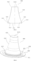
FIG. 1 is a longitudinal sectional diagram of a sheath for an ear temperature measurement apparatus in an embodiment of this disclosure. -
FIG. 2 is a structural diagram of a sheath in another embodiment of this disclosure. -
FIG. 3 is a longitudinal sectional diagram of the sheath shown inFIG.2 . -
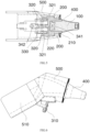
FIG. 4 is a structural diagram of control mechanism, engaging element, sheath and probe, when a sheath is fixed in an embodiment of this disclosure. -
FIG. 5 is a sectional diagram of the structure shown inFIG.4 . -
FIG. 6 is a structural diagram of sheath, housing and probe, when a sheath is fixed in an embodiment of this disclosure. -
FIG. 7 is a structural diagram of control mechanism, engaging element, sheath and probe, when a sheath is ejected in an embodiment of this disclosure. -
FIG. 8 is a sectional diagram of the structure shown inFIG.7 . -
FIG. 9 is a structural diagram of sheath, housing and probe, when a sheath is ejected in an embodiment of this disclosure. -
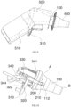
FIG. 10 is a structural diagram of control mechanism, engaging element, sheath and probe, when a manual control element is slidably arranged in an embodiment of this disclosure. -
FIG. 11 is a structural diagram of the structure shown inFIG. 1 0 with a housing. -
FIG. 12 is a structural diagram of control mechanism, engaging element, sheath and probe, when a manual control element is arranged above a housing in an embodiment of this disclosure. -
FIG. 13 is a structural diagram of the structure shown inFIG.12 with a housing. -
FIG. 14 is a structural diagram when two sheaths are stacked (in a sectional state) in an embodiment of this disclosure. -
FIG. 15 is an enlarged sectional diagram of bendable part of sheath in an embodiment of this disclosure. -
FIG. 16 is a sectional diagram showing engagement fitting between an engaging element and a sheath in an embodiment of this disclosure. -
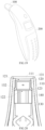
FIG. 17 is a structural diagram of reinforcing rib at a sheath in an embodiment of this disclosure. -
FIG. 18 is a partial sectional diagram of the structure shown inFIG. 17 . -
FIG. 19 is a schematic diagram of an ear temperature measurement apparatus in an embodiment of this disclosure. -
FIG. 20 is a sectional diagram showing an internal structure of probe in an embodiment of this disclosure. -
FIG. 21 is a sectional diagram of a sheath worn by a probe in an embodiment of this disclosure. - This disclosure will be further described in detail below through specific embodiments in combination with the accompanying drawings. In different embodiments, similar elements adopt associated similar reference numbers. In the following embodiments, many details are described in order to make this disclosure better understood. However, one skilled in the art can easily recognize that some of the features can be omitted in different cases, or can be replaced by other elements, materials and methods. In some cases, some operations related to this disclosure are not shown or described in the description, in order to avoid the core part of this disclosure being inundated by too many descriptions. For one skilled in the art, it is not necessary to describe these related operations in detail, as they can fully understand the relevant operations according to the description in this disclosure and the general technical knowledge in the art.
- In addition, the features, operations, or features described in the specification may be combined in any appropriate manner to form various embodiments. At the same time, the steps or actions in the method description can also be exchanged or adjusted in order in a manner obvious to one skilled in the art. Therefore, the various sequences in the description and the drawings are only for the purpose of clearly describing a certain embodiment, and do not mean that they are necessary sequences. Unless it is otherwise specified that one of the sequences must be followed.
- The terms "first", "second", etc., in the specification are operable to distinguish different objects, rather than to describe a specific order. In addition, the terms "connection", and "linkage" mentioned in this application include direct and indirect connection (linkage), unless otherwise specified.
- Embodiments provide an ear temperature measurement device. In one embodiment, the ear temperature measurement device includes an ear temperature measurement apparatus and a sheath. The ear temperature measurement apparatus can measure an ear temperature of a measured subject and acquire the ear canal temperature of the measured subject. For example, it may be an ear thermometer that measures the temperature in the ear canal by infrared spectroscopy or other detection methods.
- Please referring to
FIGS. 1-13 , in one embodiment, an ear temperature measurement apparatus includes aprobe 100, anengaging element 200, and a control mechanism. Thesheath 400 is sheathed at the ear temperature measurement apparatus to protect the probe of the ear temperature measurement apparatus. Thesheath 400 may be disposable or usable for a limited number of times to avoid cross infection. Thesheath 400 needs not only to be worn by theprobe 100, but also to be easily removed when it is disassembled. - Among them, the
probe 100 is configured to measure an ear temperature, and may have a structure that emits infrared spectrum or other detection media. Its structure may refer to the prior art. Theprobe 100 has aprobe housing 110 for preventing heat transfer, and a receiving and transmitting unit or the likes of corresponding infrared spectrum or other detection medium is installed inside theprobe housing 110. Theprobe housing 110 has a proximal end A and a distal end B for protruding into an ear canal of a measured subject, and the distal end B protrudes and extends from the proximal end A to one side. As shown inFIGS. 4-13 , in some embodiments, theprobe housing 110 is tapered or frustum shaped with a greater outer side and a smaller inner side (the distal end B facing the user is the outer side, and the proximal end A opposite to the distal end B is the inner side), so that the thinner distal end B protrudes into the ear canal of the measured object to reduce the discomfort of the measured object during measurement. Of course, the shape of theprobe 100 is not limited to that shown inFIGS. 4-13 , and may be other shapes. - Unlike the usual ear temperature measurement apparatus, in this embodiment, in order to be able to fix the
sheath 400, the engagingelement 200 has at least oneengaging part 210, which engages and fits with thesheath 400 which is sheathed at theprobe housing 110 to achieve detachable fixation. Please refer toFIGS. 4 ,5 ,7, 8 ,10 and12 . In some embodiments, theengaging part 210 may be a clip. Of course, in addition to the illustrated clip structure, other types of engagingpart 210 may also be used. In one embodiment, there may be two or more engaging elements, and thesheath 400 may be fixed from two or more positions to prevent thesheath 400 from falling off. As shown inFIGS. 4 ,5 and16 , after thesheath 400 is sheathed at theprobe housing 110, it can be engaged and fixed with theengaging element 200 to hold thesheath 400 at theprobe housing 110. - The
engaging element 200 is configured to fix thesheath 400 and eject thesheath 400 to separate it from theprobe 100, so that the user can easily remove thesheath 400. The control mechanism controls theengaging element 200 to move toward the proximal end A and the distal end B. Among them, there may be at least oneengaging element 200, and the movements of theseengaging elements 200 are all controlled by the control mechanism. An engaged position and a released position are provided on a movement path of theengaging element 200 moving toward the proximal end A. As shown inFIGS. 4 ,5 and16 , when theengaging element 200 is in the engaged position, theengaging part 210 can be engaged and fixed with thesheath 400, and can pull thesheath 400 to deform toward the proximal end A during the movement of theengaging element 200, that is, the control mechanism drives theengaging element 200 to move in the engaged position, and drives thesheath 400 to deform toward the proximal end A, and thesheath 400 accumulates potential energy in this process. When theengaging element 200 is in the released position, theengaging part 210 is disengaged from thesheath 400. That is, when theengaging part 210 of theengaging element 200 is disengaged from thesheath 400, the engagingelement 200 is switched from the engaged position to the released position, as shown inFIGS. 7, 8 and9 . At this time, the engagingelement 200 is no longer engaged with thesheath 400, and thesheath 400 is quickly ejected in the opposite direction (that is, towards where the distal end B of theprobe housing 110 is located) under its own elastic force, and falls at the distal end B of theprobe housing 110. In some embodiments, thesheath 400 can accumulate enough potential energy, such that when the outward elastic force is large enough, thesheath 400 can be directly detached from the distal end B without removing thesheath 400 by hand. The engaged position and released position may be a certain position or a stroke. - In a normal ear temperature measurement apparatus, the
sheath 400 is directly fixed to theprobe housing 110, and a pushing mechanism pushes thesheath 400 toward the distal end B of theprobe housing 110 to separate thesheath 400 from theprobe housing 110. However, due to the elasticity of thesheath 400 itself, when the pushing mechanism pushes thesheath 400 outward, thesheath 400 can absorb part of the pushing force and displacement of the pushing mechanism, resulting in pushing failure. Accordingly, thesheath 400 cannot be separated from the probe housing. - In this embodiment, please refer to
FIGS. 1-13 . The ear temperature measurement apparatus first uses theengaging element 200 to engage thesheath 400 without fixing the sheath with theprobe housing 110. When removing thesheath 400, the engagingelement 200 can be separated from thesheath 400 by directly controlling the displacement of theengaging element 200, that is, when theengaging element 200 moves toward the proximal end A of theprobe housing 110 and reaches a preset position, thesheath 400 naturally disengages from theengaging element 200 to release the fixation of thesheath 400, so that thesheath 400 can be easily ejected. At the same time, the ejection structure adopts the principle which is opposite to that of the normal ear temperature measurement apparatus. The movement of theengaging element 200 away from the distal end B drives thesheath 400 to deform toward the proximal end A of the probe housing 110 (thesheath 400 always is deformed toward the distal end B of theprobe housing 110 in the normal pushing mechanism). The force applied to thesheath 400 is similar to the bow arm in archery. When theengaging element 200 moves to the released position, the engagingelement 200 disengages from thesheath 400. At this time, thesheath 400 can not only release the locking state, but also store energy during the movement of thesheath 400 toward the proximal end A, so that it is quickly ejected in the opposite direction (i.e., towards where the distal end B of theprobe housing 110 is located) under its own elastic force. It can be seen that in this embodiment, not only the connection relationship between thesheath 400 and the probe can be easily released, but also thesheath 400 can be ejected to a side where the distal end B is located by virtue of the reverse elastic force of thesheath 400, which makes it easier to remove thesheath 400. - This embodiment also specifically designs a sheath for this ejection-type sheath disassembly mode. Referring to
FIGS. 1-3 , in one embodiment, thesheath 400 includes acylindrical body 410. Thecylindrical body 410 has afirst end 411 and asecond end 412 which is opposite to thefirst end 411. Thefirst end 411 of thecylindrical body 410 is opened to form an opening through which theprobe 100 of the ear temperature measurement apparatus protrudes into thecylindrical body 410. Thesecond end 412 of thecylindrical body 410 is closed and has awindow 4121 that can transmit infrared rays, such as an IR transparent lens. The shape of thecylindrical body 410 matches the shape of the probe housing. For example, in the embodiment shown inFIGS. 1-3 , thecylindrical body 410 may be provided with a tapered or frustum-shaped structure which matches that of theprobe housing 110. - The inner circumference surface of the
cylindrical body 410 is provided with an engaging fitting part which is configured to engage with theengaging element 200 of the ear temperature measurement apparatus to install thesheath 400 at theengaging element 200. The engaging fitting part has a structure that can be deformed toward the proximal end A of theprobe 100 and finally separated from theengaging element 200 under the driving of theengaging element 200. That is, when theengaging element 200 is in the engaged position, the engaging fitting part can be well fixed with theengaging part 210 of theengaging element 200. When theengaging element 200 moves to the released position, the engaging fitting part can be separated from theengaging part 210 of theengaging element 200 under the selfdeformation of thecylindrical body 410. - In one embodiment, referring to
FIGS. 1 and3 , the engaging fitting part is arecess part 413 which is arranged at the inner circumference surface of thecylindrical body 410. The recess structure of therecess part 413 can form a concaveconvex engagement fitting with theengaging part 210 of theengaging element 200 to fix thesheath 400. Of course, the engaging fitting part can also be designed as a convex structure, such as a bump, a raised point, a flange, etc. Correspondingly, theengaging part 210 of theengaging element 200 can also be designed as other structures that can match with the convex structure, such as a recess structure or another convex structure. Thesheath 400 and theengaging element 200 are engaged and fixed, which not only ensures the stability of the fixed connection, but also facilitates the separation of the two under a certain external force, so as to realize the convenience of assembly and disassembly. - The
recess part 413 may be a structure such as a hole or a groove etc., and the number thereof may be one or more. For example, in one embodiment, there can be a plurality ofrecess parts 413 with gaps therebetween, and therecess parts 413 are annularly distributed along the inner circumference surface of thecylindrical body 410, so as to match with theengaging element 200. - Referring to
FIGS. 1 and3 , in one embodiment, therecess parts 413 are distributed in a continuous annular shape on the inner circumference surface of thecylindrical body 410. For example, it may be one or more rings of annular grooves formed by depressions of the inner circumference surface. Each portion of therecess part 413 can be configured to match with theengaging element 200, so that thesheath 400 requires no installation angle when installed. After thesheath 400 is sheathed, the engagingelement 200 can be engaged into any area of therecess part 413. In some embodiments, therecess part 413 may be divided into several sections, and it is not necessary to form a closed state in the inner circumferential direction. - When there are a plurality of rings of annular grooves which are arranged coaxially, the
sheath 400 can also be adapted toprobes 100 of different lengths, and theengaging element 200 on theprobe 100 can be fixed to the annular groove at different depths according to its own length. Of course, the annular groove can also be replaced by other forms of engaging fitting parts. - Further, please refer to
FIGS. 3 and15 . In one embodiment, an inner wall of therecess part 413 is defined by at least one curvature. For example, the inner wall is an arc surface. The arc-shaped structure is more convenient for therecess part 413 to form an engaging fitting with theengaging element 200. When theengaging element 200 pulls therecess part 413 to deform, the overall deformation consistency of therecess part 413 is better. When theengaging element 200 moves to a specified position, it is easier to separate theengaging element 200 from therecess part 413. - Further, in some embodiments, an acute angle is formed between a tangent of any point at the inner wall of the recess part and an axis of the
cylindrical body 410. In one embodiment, the inner wall is an arc-shaped surface, and an acute angle is formed between a tangent of any point at the inner wall of the recess part and an axis of the cylindrical body, means that an acute angle is formed between any portion of therecess part 413 and the axis of thecylindrical body 410, so as to avoid therecess part 413 from forming a surface which is perpendicular to the axis of thecylindrical body 410, because such surface further increases the difficulty of separating theengaging element 200 from therecess part 413. - Please refer to
FIGS. 4 ,5 and16 . In one embodiment, the engagingelement 200 is fixed from the inner side of thesheath 400. However, in other embodiments, the engagingelement 200 may fasten and fix thesheath 400 from the outside of thesheath 400. - Further, please refer to
FIGS. 1-3 and16 . In order to better engage and fix with thesheath 400, in one embodiment, an end of theengaging part 210 which faces thesheath 400 has a bump, which is configured to engage and fix with thesheath 400. The bump has aguide surface 211 which is obliquely disposed rearward from a front end of the bump and an engagingplatform structure 212 which is located behind theguide surface 211 to guide therecess part 413 of thesheath 400 to be engaged with the engagingplatform structure 212. When theengaging element 200 moves to the released position, the engagingplatform structure 212 can also drive thesheath 400 to deform toward the distal end B of theprobe housing 110 until it is separated from thesheath 400, thereby ejecting thesheath 400. - Further, in order to disassemble the
sheath 400 more easily, please refer toFIGS. 1-3 and14 . In one embodiment, abendable part 414 is connected to a side of therecess part 413 which is adjacent to the opening. When theengaging element 200 pulls thecylindrical body 410 to deform toward the proximal end A of theprobe 100, an end of thebendable part 414 which is away from therecess part 413 abuts against the ear temperature measurement apparatus, for example, abuts against the housing or other structures of the ear temperature measurement apparatus, so that thebendable part 414 can be bent and deformed, thereby making it easier to open the engaging fitting structure between theengaging element 200 and therecess part 413 and making it easier to detach thesheath 400 from theengaging element 200. At the same time, thebendable part 414 also accumulates energy in the process of bending and deformation. When thesheath 400 is separated from theengaging element 200, thebendable part 414 can provide a reverse elastic force to thesheath 400 under its own elastic resilient force to further help thesheath 400 to be ejected from theprobe housing 110. - In one embodiment, please refer to
FIGS. 15 and 16 . When theengaging element 200 pulls thecylindrical body 410 to deform toward the proximal end A of theprobe 100, thebendable part 414 is bent and deformed toward thecylindrical body 410, for example, it substantially deforms outward in the radial direction of thecylindrical body 410, thereby changing an opening shape of therecess part 413, making the opening of therecess part 413 larger, and theengaging element 200 can be more easily detached from therecess part 413. Of course, thebendable part 414 may be bent and deformed in other different directions as long as it can achieve similar or better effects. - Please refer to
FIGS. 1 ,3 and15 . In one embodiment, thebendable part 414 is a transition part of an arc shape or a folded surface shape. This transition portion can be folded and deformed in the axial direction of thecylindrical body 410, thereby accumulating energy for thesheath 400 to rebound. At the same time, during the folding process of the transition portion, the opening of therecess part 413 can be further opened, so that thesheath 400 can be more easily separated from theengaging element 200. The transition part of arc shape or folded surface shape may have one or more continuous bended structures. - Of course, the
bendable part 414 is not limited to the shapes shown inFIGS. 1 ,3 , and15 . In order to increase the resilient force of thebendable part 414, the thickness of thebendable part 414 can be increased or reinforcing rib structure can be designed, so that thesheath 400 can be more easily rebounded when it is separated from theengaging element 200. - Further, in some embodiments, the wall thickness of the
recess part 413 of thesheath 400 is greater than a wall thickness of a region (including the second end 412) of thecylindrical body 410, which region is at a side of therecess part 413 facing thesecond end 412, such that not only thesheath 400 can have good ductility and elasticity to be attached to the probe housing, but also therecess part 413 can have sufficient thickness and strength to enable thesheath 400 and theengaging element 200 to maintain a good fixing effect. At the same time, the thicker wall thickness of therecess part 413 is also conducive to storing more energy when therecess part 413 is deformed under the action of theengaging element 200, thereby increasing the resilient force of thesheath 400 to eject it out of the probe housing. - Further, in one embodiment, the control mechanism controls the movement of the
engaging element 200 by an electrical signal or mechanical transmission mechanism. The control mechanism can transmit the external force inputted by the user to theengaging part 210 by pure mechanical transmission, as shown inFIG. 4-13 . The control mechanism can also adopt the electronic control mode, and the user inputs an instruction to remove thesheath 400. The input of the instruction can be realized by physical keys, touch control, voice recognition, image recognition, action recognition, or even by sending electrical signals from other terminals. Then, the control unit controls the corresponding electrically controlled power component to output a signal so that theengaging part 210 drives thesheath 400 to move. For example, the electrically controlled power component may be an electromagnet, a motor, a cylinder, a hydraulic cylinder, etc. - One embodiment provides a mechanical control structure. Please refer to
FIGS. 4 ,7 ,10 and12 . The control mechanism includes amanual control element 310 and a transmission mechanism. Themanual control element 310 is in transmission connection with theengaging element 200 through the transmission mechanism to control the movement of theengaging element 200. The user inputs movement and force through themanual control element 310. Themanual control element 310 can also adopt but not limited to common control elements, such as buttons, dials, triggers, push rods, knobs, etc. The transmission mechanism transmits the movement and force which are inputted by themanual control element 310 to theengaging element 200, and the transmission mode can be flexibly selected. - Please continue to refer to
FIGS. 4-13 . In one embodiment, the transmission mechanism includes adrive arm 320 and a resilient elastic element 330 (such as a spring or other forms of elastic elements). Themanual control element 310 is in transmission connection with thedrive arm 320. Specifically, themanual control element 310 is in transmission connection with the drive arm, including integral molding, fixed connection or movable connection in a manner which can transmit movement and force. Thedrive arm 320 is in transmission connection with theengaging element 200, and the resilientelastic element 330 is configured to drive the engagingelement 200 to reset, specifically to drive the engagingelement 200 to reset to the engaged position, so as to maintain theengaging element 200 at a position that can be fixed with thesheath 400. Themanual control element 310 and thedrive arm 320 may be composed of one or more components, respectively. - Please refer to
FIGS. 4-13 . In a more specific embodiment, the resilientelastic element 330 abuts between asupport seat 340 and the engaging element 200 (or the drive arm 320). When thedrive arm 320 drives theengaging element 200 to move toward the proximal end A of theprobe housing 110, the resilientelastic element 330 is compressed, contracted and deformed, to accumulate energy. When the external force of the user disappears, the resilientelastic element 330 releases energy to push thedrive arm 320 and theengaging element 200 to reset. Among them, the resilient force of the resilientelastic element 330 to theengaging element 200 is greater than the fastening force between theengaging element 200 and thesheath 400, so that thesheath 400 is stable and does not slide after being engaged and fixed. - In a more specific embodiment, please refer to
FIGS. 4-9 . The transmission mechanism includes asupport seat 340. Thedrive arm 320 is rotationally connected to thesupport seat 340. Thedrive arm 320 is rotationally connected with theengaging element 200 in a self-adjustable manner, and converts the rotation of thedrive arm 320 into a linear reciprocation movement of theengaging element 200. Thesupport seat 340 may be used only to support thedrive arm 320 and theengaging element 200, or may also be used as a support for other structures. For example, theprobe 100 may also be supported on thesupport seat 340. Of course, other structures not shown in the ear temperature measurement apparatus may also be supported on thesupport seat 340. - Since the rotation path of the
drive arm 320 conflicts with the linear reciprocation movement path of theengaging element 200, in order to ensure smooth linkage between these two, thedrive arm 320 and theengaging element 200 are rotationally connected in a self-adjustable manner, and there are many self-adjustable ways to realize the movement conversion between these two. For example, in one embodiment, thedrive arm 320 or theengaging element 200 is provided with elongated rotation fitting parts, such as elongated holes (such as waist-shaped holes), elongated grooves, or elongated protrusion, etc., such that the position of the rotation axis can be adaptively adjusted between thedrive arm 320 and theengaging element 200. At the same time, thesupport seat 340 has a position-limiting part, which may be a linear guide part, such as alinear guide groove 343, a linear guide rail, a guide shaft, a guide hole, etc. Theengaging element 200 is limited to the position-limiting part. Therefore, when thedrive arm 320 rotates, the engagingelement 200 can be driven to move on the position-limiting part. At the same time, thedrive arm 320 and theengaging element 200 can automatically adjust the position of the rotation axis through the elongated rotation fitting part, thereby converting the rotation of thedrive arm 320 into the linear reciprocation movement of theengaging element 200. In other embodiments, theprobe housing 110 may also be provided with a position-limiting part and theengaging element 200 can be guided through theprobe housing 110 or through the position-limiting part on theprobe housing 110 and the support seat. For example, please refer toFIGS. 4-13 . In one embodiment, the outer circumference surface of theprobe housing 110 is provided with a position-limiting part which is arranged along a central axis direction of theprobe housing 110, and theengaging part 210 is installed at the position-limiting part to define the movement path of theengaging part 210. In the structure shown in the figure, the position-limiting part is a position-limitinggroove 112 which is provided along the central axis direction of theprobe housing 110. Theengaging element 200 is embedded inside the position-limitinggroove 112, and the outer wall of theengaging element 200 is adjacent to the outer wall of theprobe housing 110. This facilitates the installation of thesheath 400, and prevents the gap between thesheath 400 and theprobe housing 110 from being too large due to excessive protrusion of theengaging element 200 on theprobe housing 110. - Among them, please refer to
FIGS. 4-9 . In one embodiment, the rotation axis of thedrive arm 320 relative to thesupport seat 340 is the first rotation axis. Taking the first rotation axis as the boundary, themanual control element 310 and theengaging element 200 are both directly or indirectly installed on the same side of thedrive arm 320, so that a force arm of themanual control element 310 from the first rotation axis is greater than a force arm of an action point of theengaging element 200 or the resilientelastic element 330 from the first rotation axis. Thus, a force-saving structure is formed. When the user operates themanual control element 310, he/she can overcome the elastic force of the resilientelastic element 330 with as little force as possible, and drive thesheath 400 to deform toward the distal end B of theprobe housing 110. - Please refer to
FIGS. 4-9 . In one embodiment, the resilientelastic element 330 does not directly act on thedrive arm 320, but abuts against the engagingelement 200 to drive the engagingelement 200 to the engaged position. The rotation axis of theengaging element 200 relative to thedrive arm 320 is the second rotation axis, and a force arm of themanual control element 310 from the first rotation axis is greater than a force arm of the second rotation axis from the first rotation axis, which forms a force-saving structure. - Further, please continue to refer to
FIGS. 4-9 . In a more specific embodiment, thesupport seat 340 has afirst support seat 341 and asecond support seat 342, wherein thefirst support seat 341 is fixedly connected to the proximal end A of theprobe 100, thesecond support seat 342 is fixedly connected or integrally formed with thefirst support seat 341, and thedrive arm 320 is rotatably connected to thesecond support seat 342. The resilientelastic element 330 abuts between thesecond support seat 342 and theengaging element 200 to provide a resilient elastic force. Thedrive arm 320 may be a bridging structure which is provided with two support legs. The two support legs bridge two sides of the support seat 340 (specifically, the second support seat 342) and are rotationally connected by corresponding rotation shafts. The two rotation shafts may be of an integrated structure, which is convenient for manufacturing. For example, as shown inFig. 4-9 , the two rotation shafts are formed by bending the same strip, such as atorsion spring shaft 321. Both of the two rotation shafts are fixed to themanual control element 310. The two support legs are arranged opposite to each other. When the user inputs a force from themanual control element 310, the two support legs can more stably transmit the force to thedrive arm 320. - In other embodiments, the
manual control element 310 and thedrive arm 320 may also control theengaging element 200 in a slidable manner. For example, please refer toFIGS. 10 and12 . In some embodiments, themanual control element 310 is arranged to be slidable. The transmission mechanism includes thesupport seat 340, and thedrive arm 320 is slidably arranged at the support seat 340 (including thefirst support seat 341 and the second support seat 342). In order to simplify the structure, in the structure shown inFIGS. 10 and12 , the sliding direction of thedrive arm 320 is the same as the movement direction of theengaging element 200. Themanual control element 310, the engagingelement 200 and thedrive arm 320 may be integrated, fixedly connected or movably connected in a manner which can transmit movement and force. - Please continue to refer to
FIGS. 10 and12 . In some embodiments, thesupport seat 340 has a position-limiting part, and thedrive arm 320 is installed inside the position-limiting part. The position-limiting direction of position-limiting part is consistent with the movement direction of theengaging element 200, so as to ensure that the movement direction of thedrive arm 320 is consistent with the movement direction of theengaging element 200. As shown inFIG. 10 , the position-limiting part may include a position-limitingblock 344 that fits the position-limitinggroove 322 at thedrive arm 320. As shown inFIG. 12 , the position-limiting part may include a position-limitinggroove 345 into which thedrive arm 320 is positioned. Of course, other types of position-limiting structures may be used for the position-limiting part. - In the scheme shown in
FIGS. 10 and12 , thefirst support seat 341 is fixedly connected to the proximal end A of theprobe 100, and thesecond support seat 342 is fixedly connected or integrally formed with thefirst support seat 341. The resilientelastic element 330 is installed between thefirst support seat 341 and theengaging element 200 or thedrive arm 320. The difference is that in the scheme shown inFIG. 10 , themanual control element 310 is arranged downward, and it is exposed below the housing 500 (thehousing 500 will be described in more detail later) for a lower position to facilitate the operation of the user with the index finger. In the scheme shown inFIG. 12 , themanual control element 310 is arranged upward, and is exposed above thehousing 500, so as to facilitate the operation of the user with the thumb. - Further, in the embodiments shown in
FIGS. 4-13 , the engagingelement 200 mainly moves in a straight line. In other embodiments, when theengaging element 200 moves toward the proximal end A of theprobe housing 110, its movement path may be other shapes, such as arc shape, broken line shape or other shapes, as long as it can drive thesheath 400 to deform toward the distal end B of theprobe housing 110. - Further, a position-limiting structure may be provided at any position of the
manual control element 310, thedrive arm 320 and theengaging element 200, so as to limit the movement distance of themanual control element 310, thedrive arm 320 and theengaging element 200 as a whole, and further prevent themanual control element 310, thedrive arm 320 and theengaging element 200 from moving excessively. - Further, in order to eject the
sheath 400 more easily, in some embodiments, the engagingelement 200 has at least twoengaging parts 210, which are distributed at different positions of an outside wall of theprobe housing 110 along the outer circumferential direction of theprobe housing 110, and then force thesheath 400 together from different positions of thesheath 400 to eject it. - Referring to
FIGS. 4-13 , the two engagingparts 210 are arranged side by side, and thesheath 400 is ejected outward from the two positions side by side. Further, the engagingelement 200 shown in the figure also has a connection part 220 (a portion between the two engaging parts 210). The engagingparts 210 are both connected to theconnection part 220 to form a claw structure, which extends from the proximal end A of theprobe housing 110 to the outside of theprobe housing 110. - In some embodiments, when there are two or more
engaging parts 210, the distribution position of the engagingparts 210 may be rotationally symmetric along the central axis of theprobe housing 110, so that the ejection points are evenly distributed at the outer circumference of theprobe housing 110, and thesheath 400 can be ejected more effectively. - Further, referring to
FIGS. 6 ,9 ,11 and13 , the ear temperature measurement apparatus includes ahousing 500. InFIGS. 6 ,9 ,11 and13 , only a portion of thehousing 500 is schematically drawn, but this does not affect the understanding of the present scheme. In fact, thehousing 500 in this scheme can adopt the structure of the existinghousings 500 of the same or similar products. Thehousing 500 has an installation cavity for installing various related structures, such as a circuit board, a battery, and the like. The installation cavity has an outlet of theprobe 100, the proximal end A of theprobe housing 110 is located inside the installation cavity, and the distal end B of theprobe housing 110 protrudes out of thehousing 500 from the outlet of theprobe 100. - Considering that most of the existing pushing structures are directly exposed on the
housing 500, they are not only unsightly, but also easy to be damaged. Therefore, please refer toFIGS. 6 ,9 ,11 and13 . In one embodiment, the transmission mechanism is located in the installation cavity. Themanual control element 310 is provided at thehousing 500. At least a portion of themanual control element 310 is located outside thehousing 500. For example, themanual control element 310 may mainly leave the portion that is contacted by the finger of the user outside thehousing 500, and the other portions are housed inside thehousing 500. This embodiment is more concise and beautiful on the whole, and the transmission mechanism can be protected from damage due to touching, corrosion and other reasons when the transmission mechanism is placed inside thehousing 500. - Further, please refer to
FIGS. 6 ,9 and11 . In one embodiment, thehousing 500 has a holding part 510 (only a portion of the holdingpart 510 is shown) for the user to hold. At least a portion of themanual control element 310 is located below thehousing 500, so that the index finger of the user can control themanual control element 310. This design is more ergonomic and more comfortable for the user to use. - In other embodiments, the
manual control element 310 may also be arranged at other positions. For example, please refer toFIG. 13 . Thehousing 500 has a holdingpart 510 for the user to hold. At least a portion of themanual control element 310 is located above thehousing 500. In particular, when themanual control element 310 is slidably disposed, it is more convenient for the user to operate themanual control element 310 with his thumb by disposing it above the holdingpart 510 of thehousing 500. - Further, the pressing part of the existing pushing mechanism is integrally formed with the plastic pushing housing, and it cannot be made too long (because it needs to form a lever structure, which reduces the hardness and is easily to break when pressed, if made too long). Therefore, the pressing part is usually very close to the
probe 100, that is, the front end of thehousing 500, which is far away from the holding part. It is very inconvenient for the user to press when using. In this embodiment, a transmission mechanism is configured to transmit force and movement, so the position of themanual control element 310 is not limited by materials and structures, and can be designed according to ergonomic requirements. As shown inFIGS. 6 ,9 ,11 and13 , it is arranged at a position more suitable for the finger operation of the user when hold by the user. - On the other hand, as shown in
FIG. 14 , thesheath 400 is generally packaged and transported in a stacked manner. However, when thesheath 400 is taken out of the package and worn by the ear temperature measurement apparatus, the operator needs to go through cumbersome operation steps. Usually, the operator takes out thesheath 400 one by one from the package box and then puts each sheath on the ear temperature measurement apparatus, which increases the chance of the hand of the operator to contact thesheath 400 and is not conducive to preventing cross infection. - In this regard, please refer to
FIGS. 1-3 and14 . In one embodiment, the outer circumference surface of thecylindrical body 410 has anouter support 415 which protrudes to separate twoadjacent sheaths 400 when a plurality of thesheaths 400 are stacked. The twoadjacent sheaths 400 stacked together are contacted and supported by theouter support 415, wherein the contact between the two adjacent sheaths is point contact, line contact or surface contact, which can reduce the contact area and prevent theadjacent sheaths 400 from being pressed together. - Referring to
FIGS. 3 ,14 and15 , in one embodiment, abendable part 414 is connected to the side of therecess part 413 which is adjacent to the opening. Thebendable part 414 is located below theouter support 415. As shown inFIG. 14 , thebendable part 414 is configured to contact theouter support 415 of the lower sheath when the plurality ofsheaths 400 are stacked to separate the adjacent twosheaths 400. - When engaging with the
sheath 400, the ear temperature measurement apparatus without thesheath 400 directly protrudes into the package box, and theuppermost sheath 400 in the package box is automatically attached to the ear temperature measurement apparatus by pressing, and the remainingsheaths 400 in the package box are separated by theouter support 415, and are not deformed or attached together due to the pressing. In the next time when the head of the ear temperature measurement apparatus protrudes into the package box to take way thenext sheath 400, thenext sheath 400 can be easily taken way. Each time thesheath 400 is taken out, only theuppermost sheath 400 is taken out, and noextra sheath 400 is taken out. - The
outer support 415 may be provided at various positions at the outer circumference surface of thecylindrical body 410, as if it can serve to separate the twostacked sheaths 400. Please refer toFIG. 1 ,FIG. 3 andFIG. 13 . In one embodiment, theouter support 415 is arranged away from therecess part 413. - Please refer to
FIGS. 1-3 . In a more specific embodiment, theouter support 415 includes a flange formed by protruding outward a back surface of the recess region of therecess part 413. This design is convenient for processing. When therecess part 413 is formed by injection molding, theouter support 415 can be formed synchronously. - In some embodiments, the thickness of the
recess part 413 is greater than that of other parts. This relatively greater thickness can make theouter support 415 have better support strength and not easy to deform, further preventing thesheath 400 from deforming or sticking together due to pressing when they are stacked. - Further, please refer to
FIGS. 1-3 and15 . In one embodiment, thesheath 400 further includes anannular support 420. Theannular support 420 is arranged around the opening of thecylindrical body 410 and connected with thecylindrical body 410, so that when thecylindrical body 410 is deformed toward the proximal end A of theprobe 100, theannular support 420 can abut against the ear temperature measurement apparatus (such as thehousing 500, theprobe housing 110 or other structures of the ear temperature measurement apparatus). Thus, when theengaging element 200 drives thesheath 400 to deform toward the proximal end A of theprobe 100, thesheath 400 is provided with a supporting force from theannular support 420 toward the distal end B of theprobe 100, so that thesheath 400 is compressed and deformed toward the middle area to store energy, which is more conducive to ejecting thesheath 400 after thesheath 400 is separated from theengaging element 200. - In order to improve the support effect, increase the strength and improve the effect of energy accumulation, in one embodiment, the wall thickness of the
annular support 420 is greater than the wall thickness of thefirst end 411 of thecylindrical body 410. Alternatively, referring toFIGS. 17 and 18 , some reinforcingribs 423 may be added to some or all areas of theannular support 420. For example, the reinforcingribs 423 may extend radially, obliquely side by side, or in other shapes outward along the radial direction of theannular support 420. - Please refer to
FIGS. 1-3 and15 . In one embodiment, theannular support 420 has a stepped annular surface. The annular surface includes a firstannular surface 421 which is connected to a wall of the opening and a secondannular surface 422 which is arranged around the firstannular surface 421. The firstannular surface 421 and the secondannular surface 422 are connected, and the secondannular surface 422 deviates from the firstannular surface 421 toward the distal end of theprobe 100. The firstannular surface 421 and the secondannular surface 422 may contact and support different structures at the ear temperature measurement apparatus. - In some embodiments, the
annular support 420 may also have a planar annular surface. That is, the firstannular surface 421 and the secondannular surface 422 are one annular surface in the same plane. - In addition to the stretchable ejection structure shown in this embodiment, the
annular support 420 also enables thesheath 400 to be applied to a normal pushing structure. The pushing mechanism that moves outward (toward the distal end B of the probe 100) in the ear temperature measurement structure can abut against theannular support 420 and push theannular support 420 and theentire sheath 400 to move toward the distal end of theprobe 100, thereby separating thesheath 400 from theprobe 100. - Of course, in some embodiments, the
annular support 420 may be omitted. When theengaging element 200 drives thesheath 400 to deform toward the proximal end A of theprobe 100, thesheath 400 may not contact other structures of the ear temperature measurement apparatus and be supported. Thesheath 400 may be directly contacted with and supported by other structures of the ear temperature measurement apparatus through the above describedbendable part 414 or the engaging fitting part. - Further, please refer to
FIGS. 19-21 . An embodiment of the present application also provides another ear temperature measurement apparatus, including aprobe 100 and a main body 600 which is connected to theprobe 100. Generally, the main body 600 has a housing 500 (referringFIGS. 6 ,9 ,11 and13 ) that is convenient to hold. The user holds thehousing 500 to insert theprobe 100 into the ear canal for temperature measurement. - The
probe 100 includes aprobe housing 110 for preventing heat transfer, aheat conduction element 130 and aninfrared temperature sensor 120 which are installed inside theprobe housing 110. At least one electronic component, which is electrically connected to theinfrared temperature sensor 120, is provided inside the main body 600 to output a temperature of a part to be measured by theinfrared temperature sensor 120. The electronic component includes but is not limited to necessary electronic components or modules which are formed by physical and/or signal connection of electronic components to complete the function of the ear temperature measurement apparatus, such as various board cards, circuit boards, batteries, etc. - The
probe housing 110 has a proximal end which is connected to the main body 600. The connection between theprobe housing 110 and the main body 600 has a broad meaning, such connection can be either integral formation with the main body 600 or detachably connection with the main body 600, for example, by screw connection. In addition, theprobe housing 110 also has a distal end which protrudes outward from the main body 600, and the distal end is provided with anopening 111. To facilitate inserting into a deeper position of the ear canal, theprobe housing 110 may be provided as a cone which takes the distal direction of theprobe housing 110 as a tip direction. One of the functions of theprobe housing 110 is to isolate external heat. An inner cavity of theprobe housing 110 is connected with the outside through theopening 111 at the distal end, and the heat outside theprobe housing 110 enters the inner cavity of theprobe housing 110 through theopening 111. - The
infrared temperature sensor 120 is configured to receive infrared radiation from the part to be measured through theopening 111 to measure the temperature of the part to be measured. Specifically, theinfrared temperature sensor 120 has afirst end 121 which faces theopening 111 and asecond end 122 which faces away from thefirst end 121. The window of theinfrared temperature sensor 120 is arranged at thefirst end 121, the infrared radiation from the ear canal reaches the window of theinfrared temperature sensor 120 after passing through theopening 111 of theprobe housing 110. - The
heat conduction element 130 has a tapered sheath structure, and is sheathed inside theprobe housing 110 and attached to theprobe housing 110 at theopening 111 of theprobe housing 110. The material of theheat conduction element 130 has high thermal conductivity (e.g., metal), and the material of theprobe housing 110 has low thermal conductivity. The high thermal conductivity and low thermal conductivity in this disclosure are the definitions of the thermal conductivity commonly understood in the art, and are also the definitions of the relative relationship between the thermal conductivity of theprobe housing 110 and theheat conduction element 130, that is, the thermal conductivity of theheat conduction element 130 is higher than the thermal conductivity of theprobe housing 110. Theheat conduction element 130 extends from theopening 111 to thesecond end 122 and is thermally connected to thesecond end 122 to form a heat transfer path from theopening 111 of theprobe housing 110 to thesecond end 122. The heat at theopening 111 of theprobe housing 110 is transmitted to thesecond end 122 of theinfrared temperature sensor 120 through the heat transfer path to reduce a temperature difference between thefirst end 121 and thesecond end 122 of theinfrared temperature sensor 120. In this embodiment, as shown inFIG. 20 , one end of theheat conduction element 130 which is adjacent to theopening 111 of theprobe housing 110 is below theopening 111 of theprobe housing 110, that is, it never extends out of theprobe housing 110. In other embodiments, the end of theheat conduction element 130 may be flush with theopening 111 of theprobe housing 110 or extend out of theopening 111 of theprobe housing 110. The other end of the heat conduction element 130 (the end away from theopening 111 of the probe housing 110) extends to a position which is adjacent to the main body 600. In other embodiments, the other end of theheat conduction element 130 may only extend to a position which is adjacent to thesecond end 122 of theinfrared temperature sensor 120 or to other positions. In addition, theheat conduction element 130 also has a cone structure. The conedheat conduction element 130 and the conedprobe housing 110 are attached together or almost attached together near theopening 111 near theprobe housing 110, so that heat can be prevented from entering the gap between theheat conduction element 130 and theprobe housing 110. - In some embodiments, the inner wall of the
heat conduction element 130, which is adjacent to theopening 111 of theprobe housing 110 protrudes inward to form aheated protrusion 131. The heat entering theopening 111 is transmitted to the heat transfer path by theheated protrusion 131, and then transmitted to thesecond end 122 of theinfrared temperature sensor 120 by the heat transfer path. Theheated protrusion 131 can form a circular disk in the horizontal direction. Theheated protrusion 131 can absorb more infrared energy from the measured object (such as the ear canal), so that the temperature of thesecond end 122 of theinfrared temperature sensor 120 is closer to the temperature of thefirst end 121. - The heat transfer path formed by the
heat conduction element 130 of the high thermal conductivity material transmits the heat at theopening 111 to thesecond end 122 of theinfrared temperature sensor 120 accurately and with a small error, thereby reducing the measurement error of theprobe 100. - The heat conduction connection between above-mentioned
heat conduction element 130 and thesecond end 122 of theinfrared temperature sensor 120 can be implemented in various ways, such as in direct contact heat conduction connection or indirect contact heat conduction connection, which is described by way of example below. - In some embodiments, the
second end 122 of theinfrared temperature sensor 120 is directly adhered to the inner wall of theheat conduction element 130 through a heat conduction adhesive, thereby completing the heat conduction connection with theheat conduction element 130. - In some embodiments, the ear temperature measurement apparatus further includes a
heat insulation support 140. The inner wall of theheat conduction element 130 protrudes inward to form afirst boss 132, thesecond end 122 of theinfrared temperature sensor 120 protrudes outward to form asecond boss 123 which matches with thefirst boss 132, theheat insulation support 140 is fixedly installed inside theprobe housing 110. One end of theheat insulation support 140 abuts against thesecond end 122 of theinfrared temperature sensor 120, and applies a force to theinfrared temperature sensor 120 to press thesecond boss 123 against thefirst boss 132. In this way, theheat conduction element 130 and theinfrared temperature sensor 120 are overlapped by thefirst boss 132 and thesecond boss 123 to fix theinfrared temperature sensor 120. In some embodiments, there is an air gap and/or a heat insulation medium between theheat conduction element 130 and theinfrared temperature sensor 120 except the overlap joint between thefirst boss 132 and thesecond boss 123, that is, theinfrared temperature sensor 120 is thermally connected to theheat conduction element 130 only through thesecond end 122, so as to avoid heat loss. - In some embodiments, the
heat insulation support 140 may be an elastic support made of a heat insulation material. One end of the elastic support is connected to the main body 600 for fixation, and the other end abuts against thesecond end 122 of theinfrared temperature sensor 120. In other embodiments, theheat insulation support 140 includes a spring and a heat insulation element. The spring is fixedly installed inside theprobe housing 110, and one end of the spring presses the heat insulation element against thesecond end 122 of theinfrared temperature sensor 120 through its own elastic force. - In some embodiments, the material of the
heat insulation support 140 may be a filling foam or other material with low thermal conductivity, which plays a support role after fixation, or it may be a liquid glue of epoxy resin. - In addition to the above two types of heat conduction connection between above-mentioned
heat conduction element 130 and thesecond end 122 of theinfrared temperature sensor 120, in other embodiments, the inner wall of theheat conduction element 130 is provided with a first installation structure, thesecond end 122 of theinfrared temperature sensor 120 is provided with a second installation structure, and theinfrared temperature sensor 120 is fixed to theheat conduction element 130 through the fitting of the first installation structure and the second installation structure. For example, the first installation structure is a clamping slot provided at the inner wall of theheat conduction element 130, and the second installation structure is a heat conduction clamping claw provided at thesecond end 122 of theinfrared temperature sensor 120. For example, the inner wall of theheat conduction element 130 is provided with an internal thread, the side wall of thesecond end 122 of theinfrared temperature sensor 120 is provided with an external thread, and thesecond end 122 of theinfrared temperature sensor 120 is threadedly connected with theheat conduction element 130, Other examples of the first installation structure and the second installation structure are not described here. - When the ear temperature measurement apparatus is in use, the
probe housing 110 can be directly inserted into the ear canal to complete the temperature measurement. For the sake of more safety and hygiene, in some embodiments, the ear temperature measurement apparatus further includes asheath 400, which is detachably sheathed at theprobe housing 110. For example, thesheath 400 can be used once, making the ear temperature measurement apparatus safer and hygienic. It should be noted that theprobe housing 110 of this disclosure can isolate heat and prevent ambient temperature from affecting the measurement of theinfrared temperature sensor 120, so thesheath 400 does not need to have a heat insulation function, that is, thesheath 400 can be made thinner than thesheath 400 used in other ear temperature measurement apparatus, thereby reducing the cost of consumables. - In some embodiments, the
sheath 400 may be made of an elastic material and worn by theprobe housing 110 through its own deformation. In other embodiments, the ear temperature measurement apparatus further includes anengaging element 200, which is provided at the main body 600. Theengaging element 200 is configured to eject thesheath 400 which is sheathed at theprobe housing 110 from theprobe housing 110, so as to separate thesheath 400 from theprobe housing 110. As shown inFIG. 21 , one embodiment of theengaging element 200 is an example of theengaging element 200. - As shown in the previous embodiments, the activities of the
engaging element 200 can be controlled by the control mechanism. Thehousing 500 has a fixedend 520, which is connected to the main body 600 and provided with a through-hole inside thefixed end 520. Theengaging element 200 passes through the through-hole and is connected with the main body 600 through the resilientelastic element 330. By applying a force along the axial direction of the resilientelastic element 330 to theengaging element 200, the engagingelement 200 can be controlled to reciprocate in the through-hole of thefixed end 520. The end of theengaging element 200 which is adjacent to theopening 111 of theprobe housing 110 protrudes outward to form anengaging part 210 which is inclined toward the main body 600. -
FIG. 21 is a schematic diagram of thesheath 400 which is worn by theprobe housing 110. Thesheath 400 as a whole has a conical structure like theprobe housing 110. The right end of thesheath 400 in this figure may be referred to as the second end of thesheath 400, and the left end of thesheath 400 in this figure may be referred to as the first end of thesheath 400. The first end of thesheath 400 extends outward to form anannular support 420, and the side wall of thesheath 400 which is adjacent to the first end is concave inward to form arecess part 413 that fits with theengaging part 210. - The process of fitting the
sheath 400 to theprobe housing 110 is to move thesheath 400 so that theprobe housing 110 enters thesheath 400 from the first end of thesheath 400. Since thesheath 400 is elastic, thesheath 400 is stretched during the movement, so that therecess part 413 at thesheath 400 is deformed to fit with theengaging part 210, so that thesheath 400 is fixed to theprobe housing 110. - The process of ejecting the
sheath 400 from theprobe housing 110 is as follows. As shown inFIG. 21 , a leftward force is applied to theengaging element 200. During the leftward movement of theengaging element 200, therecess part 413 of thesheath 400 is also moved leftward. At this time, theannular support 420 is bent and deformed because it abuts against the fixed portion and cannot move. After theengaging element 200 moves to a certain position, it is separated from thesheath 400, and thesheath 400 is ejected by the energy storage of thecylindrical body 410 and theannular support 420. - The present disclosure also provides a
probe 100 for a temperature measurement apparatus. Theprobe 100 is different from theprobe 100 for the ear temperature measurement apparatus described above in that it can be used in other temperature measurement apparatus, and the shape of theprobe housing 110 of theprobe 100 can be changed according to the application, and is not limited to the cone. - The probe of the above embodiment realizes the accurate conduction of heat through the heat transfer path formed by the heat conduction element, reduces the temperature difference between the two ends of the infrared temperature sensor, and makes the measurement more accurate. In addition, the ear temperature measurement apparatus described above has low cost and is convenient to use.
- The above description is only the specific embodiments of the present disclosure, and the present disclosure is not limited to these specific embodiments. Those skilled in the art can make various changes and modifications to the present disclosure without departing from the spirit and scope of the present disclosure.
Claims (15)
- A sheath for an ear temperature measurement apparatus, characterized in that, comprising:
a cylindrical body which is provided with a first end and a second end which is opposite to the first end, wherein the first end of the cylindrical body is opened to form an opening through which a probe of the ear temperature measurement apparatus protrudes into the cylindrical body, the second end of the cylindrical body is closed and has a window which can transmit an infrared ray, wherein an inner circumference surface of the cylindrical body is provided with an engaging fitting part, which is configured to engage with an engaging element of the ear temperature measurement apparatus to install the sheath at the engaging element and is configured to be deformed toward a proximal end of the probe and finally be disengaged from the engaging element under a pull of the engaging element. - The sheath according to claim 1, characterized in that, the engaging fitting part is a recess part which is arranged at the inner circumference surface of the cylindrical body.
- The sheath according to claim 2, characterized in that, the recess part is distributed in a continuous annular shape at the inner circumference surface of the cylindrical body; or
the recess part comprises a plurality of recess parts with gaps therebetween and the plurality of recess parts are distributed in a continuous annular shape at the inner circumference surface of the cylindrical body. - The sheath according to claim 2, characterized in that, a bendable part is connected to a side of the recess part which is adjacent to the opening, and when the engaging element drives the cylindrical body to deform toward the proximal end of the probe, the bendable part can be bent and deformed toward the cylindrical body.
- The sheath according to claim 2, characterized in that, an outer circumference surface of the cylindrical body is provided with an outer support which protrudes to separate two adjacent sheaths when a plurality of the sheaths are stacked.
- The sheath according to claim 5, characterized in that, the outer support comprises a flange which is formed by protruding outward a back surface of a recess region of the recess part.
- The sheath according to claim 5, characterized in that, a bendable part is connected to a side of the recess part which is adjacent to the opening, wherein the bendable part is located below the outer support and configured to contact the outer support of a lower sheath to separate two adjacent sheaths when the plurality of the sheaths are stacked.
- The sheath according to claim 2, characterized in that, a wall thickness of the recess part is greater than a wall thickness of the second end of the cylindrical body.
- The sheath according to any one of claims 1-8, characterized in that, the sheath further comprises an annular support which is arranged around the opening of the cylindrical body and connected with the cylindrical body, wherein the annular support is configured to abut against the ear temperature measurement apparatus when the cylindrical body is deformed toward the proximal end of the probe.
- The sheath according to claim 9, characterized in that, a wall thickness of the annular support is greater than a wall thickness of the first end of the cylindrical body.
- The sheath according to claim 9, characterized in that, the annular support has a planar annular surface.
- The sheath according to claim 9, characterized in that, the annular support has a stepped annular surface, the annular surface comprises a first annular surface which extends from a wall of the opening and a second annular surface which is arranged around the first annular surface, wherein the second annular surface extends and forms from the first annular surface, and the second annular surface deviates from the first annular surface toward a distal end of the probe.
- The sheath according to claim 2, characterized in that, an inner wall of the recess part is defined by at least one curvature; preferably, an acute angle is formed between a tangent of any point at the inner wall of the recess part and an axis of the cylindrical body.
- An ear temperature measurement device, characterized in that, comprising an ear temperature measurement apparatus and the sheath according to any one of claims 1-13, wherein the ear temperature measurement apparatus comprises:a probe, which is configured to measure an ear temperature, wherein the probe comprises a probe housing which is provided with a proximal end and a distal end for protruding into an ear of a measured object, wherein the sheath is detachably sheathed at the probe housing;an engaging element, which is engaged with the engaging fitting part of the sheath to engage the sheath onto the probe; anda control mechanism, which is connected with the engaging element to control the engaging element to move toward the proximal end of the probe housing; wherein when the engaging element moves toward the proximal end of the probe housing, the engaging element pulls the sheath to deform toward the proximal end of the probe housing until the engaging element disengages from the sheath, thereby ejecting the sheath toward the distal end of the probe housing.
- The ear temperature measurement device according to claim 14, characterized in that, the probe housing prevents heat transfer, and the probe further comprises a heat conduction element and an infrared temperature sensor, which are installed inside the probe housing;wherein the distal end of the probe housing is provided with an opening, the infrared temperature sensor is configured to receive infrared radiation from a part to be measured through the opening to measure a temperature thereof, and the infrared temperature sensor comprises a first end which faces the opening and a second end which faces away from the first end;the heat conduction element is connected with the probe housing at the opening and extends from the opening to the second end of the infrared temperature sensor, so as to be thermally connected with the second end of the infrared temperature sensor to form a heat transfer path from the opening of the probe housing to the second end of the infrared temperature sensor, wherein heat at the opening is transmitted to the second end of the infrared temperature sensor through the heat transfer path, so as to reduce a temperature difference between the first end and the second end of the infrared temperature sensor.
Applications Claiming Priority (1)
| Application Number | Priority Date | Filing Date | Title |
|---|---|---|---|
| CN202111145978.3A CN115900963A (en) | 2021-09-28 | 2021-09-28 | Sheaths and ear temperature measuring equipment applied to ear temperature measuring devices |
Publications (1)
| Publication Number | Publication Date |
|---|---|
| EP4155695A1 true EP4155695A1 (en) | 2023-03-29 |
Family
ID=83506464
Family Applications (1)
| Application Number | Title | Priority Date | Filing Date |
|---|---|---|---|
| EP22198222.6A Pending EP4155695A1 (en) | 2021-09-28 | 2022-09-28 | Sheath for ear temperature measurement apparatus and ear temperature measurement device |
Country Status (2)
| Country | Link |
|---|---|
| EP (1) | EP4155695A1 (en) |
| CN (1) | CN115900963A (en) |
Cited By (1)
| Publication number | Priority date | Publication date | Assignee | Title |
|---|---|---|---|---|
| CN116616766A (en) * | 2023-07-10 | 2023-08-22 | 深圳市瑞邦医疗科技有限公司 | Percutaneous jaundice tester |
Families Citing this family (1)
| Publication number | Priority date | Publication date | Assignee | Title |
|---|---|---|---|---|
| CN119023075B (en) * | 2024-08-14 | 2025-11-21 | 深圳市福瑞诺科技有限公司 | Ear thermometer with low heat conduction probe |
Citations (5)
| Publication number | Priority date | Publication date | Assignee | Title |
|---|---|---|---|---|
| EP0472490A1 (en) * | 1990-08-24 | 1992-02-26 | Thermoscan Inc. | Unitary probe cover |
| WO1997042475A1 (en) * | 1996-05-07 | 1997-11-13 | Thermoscan, Inc. | Protective cover for an infrared thermometer |
| US20060239332A1 (en) * | 2002-12-12 | 2006-10-26 | Sherwood Services Ag | Thermal tympanic thermometer |
| WO2010078219A1 (en) * | 2008-12-29 | 2010-07-08 | Kaz Europe Sa | Probe cover with matching feature for a medical thermometer |
| US20120027047A1 (en) * | 2009-04-09 | 2012-02-02 | Kaz Usa, Inc. | Ir thermometry probe cover |
-
2021
- 2021-09-28 CN CN202111145978.3A patent/CN115900963A/en active Pending
-
2022
- 2022-09-28 EP EP22198222.6A patent/EP4155695A1/en active Pending
Patent Citations (5)
| Publication number | Priority date | Publication date | Assignee | Title |
|---|---|---|---|---|
| EP0472490A1 (en) * | 1990-08-24 | 1992-02-26 | Thermoscan Inc. | Unitary probe cover |
| WO1997042475A1 (en) * | 1996-05-07 | 1997-11-13 | Thermoscan, Inc. | Protective cover for an infrared thermometer |
| US20060239332A1 (en) * | 2002-12-12 | 2006-10-26 | Sherwood Services Ag | Thermal tympanic thermometer |
| WO2010078219A1 (en) * | 2008-12-29 | 2010-07-08 | Kaz Europe Sa | Probe cover with matching feature for a medical thermometer |
| US20120027047A1 (en) * | 2009-04-09 | 2012-02-02 | Kaz Usa, Inc. | Ir thermometry probe cover |
Cited By (1)
| Publication number | Priority date | Publication date | Assignee | Title |
|---|---|---|---|---|
| CN116616766A (en) * | 2023-07-10 | 2023-08-22 | 深圳市瑞邦医疗科技有限公司 | Percutaneous jaundice tester |
Also Published As
| Publication number | Publication date |
|---|---|
| CN115900963A (en) | 2023-04-04 |
Similar Documents
| Publication | Publication Date | Title |
|---|---|---|
| TW412635B (en) | Probe cover removal mechanism and ear type clinical thermometer | |
| US11592335B2 (en) | Ear thermometer with a probe cover ejection device | |
| CN102667429B (en) | Multi-point attachment for ear thermometers | |
| EP2414015B1 (en) | Laryngoscope and system | |
| US4343185A (en) | Temperature sensing probe and disposable probe cover | |
| WO1998055841A2 (en) | Tympanic thermometer with modular sensing probe | |
| EP1304555B1 (en) | Ear type clinical thermometer | |
| US4588306A (en) | Electronic thermometer probe assembly | |
| EP1817559B1 (en) | Probe cover for thermometry apparatus | |
| CN107088043B (en) | Disposable medical endoscope | |
| CN112401309B (en) | Charging device and smoking equipment with same | |
| CN115900963A (en) | Sheaths and ear temperature measuring equipment applied to ear temperature measuring devices | |
| EP1037556A1 (en) | Protective two position shell for an infrared thermometer | |
| JPWO2009044594A1 (en) | Puncture set | |
| US20210204805A1 (en) | Medical devices with battery removal | |
| US20060120432A1 (en) | Tympanic thermometer with ejection mechanism | |
| US3738172A (en) | Temperature sensing probe and disposable probe cover | |
| CN115900952A (en) | Ear Temperature Measuring Device | |
| CN201488815U (en) | Infrared Body Temperature Measuring Device | |
| US20110305257A1 (en) | Temperature Measuring Apparatus | |
| CN100422704C (en) | Tympanic thermometer with pop-up mechanism | |
| CN115876326A (en) | Ear temperature measuring device | |
| CN209858102U (en) | A hidden earmuff ejection device for an ear thermometer | |
| CN115876327A (en) | Ear thermometer and probe of temperature measuring device | |
| CN223216986U (en) | Ear temperature detection equipment |
Legal Events
| Date | Code | Title | Description |
|---|---|---|---|
| PUAI | Public reference made under article 153(3) epc to a published international application that has entered the european phase |
Free format text: ORIGINAL CODE: 0009012 |
|
| STAA | Information on the status of an ep patent application or granted ep patent |
Free format text: STATUS: REQUEST FOR EXAMINATION WAS MADE |
|
| 17P | Request for examination filed |
Effective date: 20220928 |
|
| AK | Designated contracting states |
Kind code of ref document: A1 Designated state(s): AL AT BE BG CH CY CZ DE DK EE ES FI FR GB GR HR HU IE IS IT LI LT LU LV MC MK MT NL NO PL PT RO RS SE SI SK SM TR |
|
| STAA | Information on the status of an ep patent application or granted ep patent |
Free format text: STATUS: EXAMINATION IS IN PROGRESS |
|
| 17Q | First examination report despatched |
Effective date: 20250319 |