EP4155626A1 - Heat exchanger, outdoor unit equipped with heat exchanger, and air conditioner equipped with outdoor unit - Google Patents
Heat exchanger, outdoor unit equipped with heat exchanger, and air conditioner equipped with outdoor unit Download PDFInfo
- Publication number
- EP4155626A1 EP4155626A1 EP20936983.4A EP20936983A EP4155626A1 EP 4155626 A1 EP4155626 A1 EP 4155626A1 EP 20936983 A EP20936983 A EP 20936983A EP 4155626 A1 EP4155626 A1 EP 4155626A1
- Authority
- EP
- European Patent Office
- Prior art keywords
- heat exchanger
- heat exchange
- refrigerant
- exchange body
- region
- Prior art date
- Legal status (The legal status is an assumption and is not a legal conclusion. Google has not performed a legal analysis and makes no representation as to the accuracy of the status listed.)
- Granted
Links
Images




Classifications
-
- F—MECHANICAL ENGINEERING; LIGHTING; HEATING; WEAPONS; BLASTING
- F28—HEAT EXCHANGE IN GENERAL
- F28D—HEAT-EXCHANGE APPARATUS, NOT PROVIDED FOR IN ANOTHER SUBCLASS, IN WHICH THE HEAT-EXCHANGE MEDIA DO NOT COME INTO DIRECT CONTACT
- F28D1/00—Heat-exchange apparatus having stationary conduit assemblies for one heat-exchange medium only, the media being in contact with different sides of the conduit wall, in which the other heat-exchange medium is a large body of fluid, e.g. domestic or motor car radiators
- F28D1/02—Heat-exchange apparatus having stationary conduit assemblies for one heat-exchange medium only, the media being in contact with different sides of the conduit wall, in which the other heat-exchange medium is a large body of fluid, e.g. domestic or motor car radiators with heat-exchange conduits immersed in the body of fluid
- F28D1/04—Heat-exchange apparatus having stationary conduit assemblies for one heat-exchange medium only, the media being in contact with different sides of the conduit wall, in which the other heat-exchange medium is a large body of fluid, e.g. domestic or motor car radiators with heat-exchange conduits immersed in the body of fluid with tubular conduits
- F28D1/053—Heat-exchange apparatus having stationary conduit assemblies for one heat-exchange medium only, the media being in contact with different sides of the conduit wall, in which the other heat-exchange medium is a large body of fluid, e.g. domestic or motor car radiators with heat-exchange conduits immersed in the body of fluid with tubular conduits the conduits being straight
- F28D1/0535—Heat-exchange apparatus having stationary conduit assemblies for one heat-exchange medium only, the media being in contact with different sides of the conduit wall, in which the other heat-exchange medium is a large body of fluid, e.g. domestic or motor car radiators with heat-exchange conduits immersed in the body of fluid with tubular conduits the conduits being straight the conduits having a non-circular cross-section
- F28D1/05366—Assemblies of conduits connected to common headers, e.g. core type radiators
- F28D1/05391—Assemblies of conduits connected to common headers, e.g. core type radiators with multiple rows of conduits or with multi-channel conduits combined with a particular flow pattern, e.g. multi-row multi-stage radiators
-
- F—MECHANICAL ENGINEERING; LIGHTING; HEATING; WEAPONS; BLASTING
- F25—REFRIGERATION OR COOLING; COMBINED HEATING AND REFRIGERATION SYSTEMS; HEAT PUMP SYSTEMS; MANUFACTURE OR STORAGE OF ICE; LIQUEFACTION SOLIDIFICATION OF GASES
- F25B—REFRIGERATION MACHINES, PLANTS OR SYSTEMS; COMBINED HEATING AND REFRIGERATION SYSTEMS; HEAT PUMP SYSTEMS
- F25B39/00—Evaporators; Condensers
- F25B39/02—Evaporators
-
- F—MECHANICAL ENGINEERING; LIGHTING; HEATING; WEAPONS; BLASTING
- F25—REFRIGERATION OR COOLING; COMBINED HEATING AND REFRIGERATION SYSTEMS; HEAT PUMP SYSTEMS; MANUFACTURE OR STORAGE OF ICE; LIQUEFACTION SOLIDIFICATION OF GASES
- F25B—REFRIGERATION MACHINES, PLANTS OR SYSTEMS; COMBINED HEATING AND REFRIGERATION SYSTEMS; HEAT PUMP SYSTEMS
- F25B39/00—Evaporators; Condensers
- F25B39/04—Condensers
-
- F—MECHANICAL ENGINEERING; LIGHTING; HEATING; WEAPONS; BLASTING
- F28—HEAT EXCHANGE IN GENERAL
- F28D—HEAT-EXCHANGE APPARATUS, NOT PROVIDED FOR IN ANOTHER SUBCLASS, IN WHICH THE HEAT-EXCHANGE MEDIA DO NOT COME INTO DIRECT CONTACT
- F28D1/00—Heat-exchange apparatus having stationary conduit assemblies for one heat-exchange medium only, the media being in contact with different sides of the conduit wall, in which the other heat-exchange medium is a large body of fluid, e.g. domestic or motor car radiators
- F28D1/02—Heat-exchange apparatus having stationary conduit assemblies for one heat-exchange medium only, the media being in contact with different sides of the conduit wall, in which the other heat-exchange medium is a large body of fluid, e.g. domestic or motor car radiators with heat-exchange conduits immersed in the body of fluid
- F28D1/04—Heat-exchange apparatus having stationary conduit assemblies for one heat-exchange medium only, the media being in contact with different sides of the conduit wall, in which the other heat-exchange medium is a large body of fluid, e.g. domestic or motor car radiators with heat-exchange conduits immersed in the body of fluid with tubular conduits
- F28D1/0408—Multi-circuit heat exchangers, e.g. integrating different heat exchange sections in the same unit or heat exchangers for more than two fluids
- F28D1/0417—Multi-circuit heat exchangers, e.g. integrating different heat exchange sections in the same unit or heat exchangers for more than two fluids with particular circuits for the same heat exchange medium, e.g. with the heat exchange medium flowing through sections having different heat exchange capacities or for heating/cooling the heat exchange medium at different temperatures
-
- F—MECHANICAL ENGINEERING; LIGHTING; HEATING; WEAPONS; BLASTING
- F28—HEAT EXCHANGE IN GENERAL
- F28F—DETAILS OF HEAT-EXCHANGE AND HEAT-TRANSFER APPARATUS, OF GENERAL APPLICATION
- F28F1/00—Tubular elements; Assemblies of tubular elements
- F28F1/10—Tubular elements and assemblies thereof with means for increasing heat-transfer area, e.g. with fins, with projections, with recesses
- F28F1/12—Tubular elements and assemblies thereof with means for increasing heat-transfer area, e.g. with fins, with projections, with recesses the means being only outside the tubular element
- F28F1/126—Tubular elements and assemblies thereof with means for increasing heat-transfer area, e.g. with fins, with projections, with recesses the means being only outside the tubular element consisting of zig-zag shaped fins
- F28F1/128—Fins with openings, e.g. louvered fins
-
- F—MECHANICAL ENGINEERING; LIGHTING; HEATING; WEAPONS; BLASTING
- F28—HEAT EXCHANGE IN GENERAL
- F28F—DETAILS OF HEAT-EXCHANGE AND HEAT-TRANSFER APPARATUS, OF GENERAL APPLICATION
- F28F9/00—Casings; Header boxes; Auxiliary supports for elements; Auxiliary members within casings
- F28F9/02—Header boxes; End plates
- F28F9/0202—Header boxes having their inner space divided by partitions
-
- F—MECHANICAL ENGINEERING; LIGHTING; HEATING; WEAPONS; BLASTING
- F28—HEAT EXCHANGE IN GENERAL
- F28F—DETAILS OF HEAT-EXCHANGE AND HEAT-TRANSFER APPARATUS, OF GENERAL APPLICATION
- F28F9/00—Casings; Header boxes; Auxiliary supports for elements; Auxiliary members within casings
- F28F9/02—Header boxes; End plates
- F28F9/0202—Header boxes having their inner space divided by partitions
- F28F9/0204—Header boxes having their inner space divided by partitions for elongated header box, e.g. with transversal and longitudinal partitions
- F28F9/0209—Header boxes having their inner space divided by partitions for elongated header box, e.g. with transversal and longitudinal partitions having only transversal partitions
-
- F—MECHANICAL ENGINEERING; LIGHTING; HEATING; WEAPONS; BLASTING
- F28—HEAT EXCHANGE IN GENERAL
- F28F—DETAILS OF HEAT-EXCHANGE AND HEAT-TRANSFER APPARATUS, OF GENERAL APPLICATION
- F28F9/00—Casings; Header boxes; Auxiliary supports for elements; Auxiliary members within casings
- F28F9/02—Header boxes; End plates
- F28F9/0202—Header boxes having their inner space divided by partitions
- F28F9/0204—Header boxes having their inner space divided by partitions for elongated header box, e.g. with transversal and longitudinal partitions
- F28F9/0209—Header boxes having their inner space divided by partitions for elongated header box, e.g. with transversal and longitudinal partitions having only transversal partitions
- F28F9/0212—Header boxes having their inner space divided by partitions for elongated header box, e.g. with transversal and longitudinal partitions having only transversal partitions the partitions being separate elements attached to header boxes
-
- F—MECHANICAL ENGINEERING; LIGHTING; HEATING; WEAPONS; BLASTING
- F28—HEAT EXCHANGE IN GENERAL
- F28F—DETAILS OF HEAT-EXCHANGE AND HEAT-TRANSFER APPARATUS, OF GENERAL APPLICATION
- F28F9/00—Casings; Header boxes; Auxiliary supports for elements; Auxiliary members within casings
- F28F9/02—Header boxes; End plates
- F28F9/026—Header boxes; End plates with static flow control means, e.g. with means for uniformly distributing heat exchange media into conduits
- F28F9/0278—Header boxes; End plates with static flow control means, e.g. with means for uniformly distributing heat exchange media into conduits in the form of stacked distribution plates or perforated plates arranged over end plates
-
- F—MECHANICAL ENGINEERING; LIGHTING; HEATING; WEAPONS; BLASTING
- F28—HEAT EXCHANGE IN GENERAL
- F28F—DETAILS OF HEAT-EXCHANGE AND HEAT-TRANSFER APPARATUS, OF GENERAL APPLICATION
- F28F9/00—Casings; Header boxes; Auxiliary supports for elements; Auxiliary members within casings
- F28F9/02—Header boxes; End plates
- F28F9/026—Header boxes; End plates with static flow control means, e.g. with means for uniformly distributing heat exchange media into conduits
- F28F9/028—Header boxes; End plates with static flow control means, e.g. with means for uniformly distributing heat exchange media into conduits by using inserts for modifying the pattern of flow inside the header box, e.g. by using flow restrictors or permeable bodies or blocks with channels
-
- F—MECHANICAL ENGINEERING; LIGHTING; HEATING; WEAPONS; BLASTING
- F25—REFRIGERATION OR COOLING; COMBINED HEATING AND REFRIGERATION SYSTEMS; HEAT PUMP SYSTEMS; MANUFACTURE OR STORAGE OF ICE; LIQUEFACTION SOLIDIFICATION OF GASES
- F25B—REFRIGERATION MACHINES, PLANTS OR SYSTEMS; COMBINED HEATING AND REFRIGERATION SYSTEMS; HEAT PUMP SYSTEMS
- F25B13/00—Compression machines, plants or systems, with reversible cycle
-
- F—MECHANICAL ENGINEERING; LIGHTING; HEATING; WEAPONS; BLASTING
- F28—HEAT EXCHANGE IN GENERAL
- F28D—HEAT-EXCHANGE APPARATUS, NOT PROVIDED FOR IN ANOTHER SUBCLASS, IN WHICH THE HEAT-EXCHANGE MEDIA DO NOT COME INTO DIRECT CONTACT
- F28D1/00—Heat-exchange apparatus having stationary conduit assemblies for one heat-exchange medium only, the media being in contact with different sides of the conduit wall, in which the other heat-exchange medium is a large body of fluid, e.g. domestic or motor car radiators
- F28D1/02—Heat-exchange apparatus having stationary conduit assemblies for one heat-exchange medium only, the media being in contact with different sides of the conduit wall, in which the other heat-exchange medium is a large body of fluid, e.g. domestic or motor car radiators with heat-exchange conduits immersed in the body of fluid
- F28D2001/0253—Particular components
- F28D2001/026—Cores
- F28D2001/0273—Cores having special shape, e.g. curved, annular
-
- F—MECHANICAL ENGINEERING; LIGHTING; HEATING; WEAPONS; BLASTING
- F28—HEAT EXCHANGE IN GENERAL
- F28D—HEAT-EXCHANGE APPARATUS, NOT PROVIDED FOR IN ANOTHER SUBCLASS, IN WHICH THE HEAT-EXCHANGE MEDIA DO NOT COME INTO DIRECT CONTACT
- F28D1/00—Heat-exchange apparatus having stationary conduit assemblies for one heat-exchange medium only, the media being in contact with different sides of the conduit wall, in which the other heat-exchange medium is a large body of fluid, e.g. domestic or motor car radiators
- F28D1/02—Heat-exchange apparatus having stationary conduit assemblies for one heat-exchange medium only, the media being in contact with different sides of the conduit wall, in which the other heat-exchange medium is a large body of fluid, e.g. domestic or motor car radiators with heat-exchange conduits immersed in the body of fluid
- F28D2001/0253—Particular components
- F28D2001/026—Cores
- F28D2001/028—Cores with empty spaces or with additional elements integrated into the cores
-
- F—MECHANICAL ENGINEERING; LIGHTING; HEATING; WEAPONS; BLASTING
- F28—HEAT EXCHANGE IN GENERAL
- F28D—HEAT-EXCHANGE APPARATUS, NOT PROVIDED FOR IN ANOTHER SUBCLASS, IN WHICH THE HEAT-EXCHANGE MEDIA DO NOT COME INTO DIRECT CONTACT
- F28D21/00—Heat-exchange apparatus not covered by any of the groups F28D1/00 - F28D20/00
- F28D2021/0019—Other heat exchangers for particular applications; Heat exchange systems not otherwise provided for
- F28D2021/0068—Other heat exchangers for particular applications; Heat exchange systems not otherwise provided for for refrigerant cycles
-
- F—MECHANICAL ENGINEERING; LIGHTING; HEATING; WEAPONS; BLASTING
- F28—HEAT EXCHANGE IN GENERAL
- F28D—HEAT-EXCHANGE APPARATUS, NOT PROVIDED FOR IN ANOTHER SUBCLASS, IN WHICH THE HEAT-EXCHANGE MEDIA DO NOT COME INTO DIRECT CONTACT
- F28D21/00—Heat-exchange apparatus not covered by any of the groups F28D1/00 - F28D20/00
- F28D2021/0019—Other heat exchangers for particular applications; Heat exchange systems not otherwise provided for
- F28D2021/0068—Other heat exchangers for particular applications; Heat exchange systems not otherwise provided for for refrigerant cycles
- F28D2021/007—Condensers
-
- F—MECHANICAL ENGINEERING; LIGHTING; HEATING; WEAPONS; BLASTING
- F28—HEAT EXCHANGE IN GENERAL
- F28D—HEAT-EXCHANGE APPARATUS, NOT PROVIDED FOR IN ANOTHER SUBCLASS, IN WHICH THE HEAT-EXCHANGE MEDIA DO NOT COME INTO DIRECT CONTACT
- F28D21/00—Heat-exchange apparatus not covered by any of the groups F28D1/00 - F28D20/00
- F28D2021/0019—Other heat exchangers for particular applications; Heat exchange systems not otherwise provided for
- F28D2021/008—Other heat exchangers for particular applications; Heat exchange systems not otherwise provided for for vehicles
- F28D2021/0084—Condensers
Definitions
- the present disclosure relates to a heat exchanger including a plurality of flat tubes, an outdoor unit including the heat exchanger, and an air-conditioning apparatus including the outdoor unit.
- a given existing heat exchanger includes a plurality of flat tubes extending in a vertical direction and spaced from each other in a horizontal direction, a plurality of fins which are each connected between associated adjacent ones of the flat tubes and which transfer heat to the flat tubes, and headers provided at upper and lower ends of the flat tubes (see, for example, Patent Literature 1).
- the heat exchanger of Patent Literature 1 is provided in an outdoor unit of an air-conditioning apparatus that is capable of both cooling operation and heating operation.
- frost forms on the heat exchanger.
- a defrosting operation of causing the frost on a surface of the heat exchanger to melt is performed.
- high-temperature and high-pressure gas refrigerant is caused to flow into the flat tubes though one of the headers, to thereby remove the frost.
- Patent Literature 1 Japanese Unexamined Patent Application Publication No. 2018-96638
- the present disclosure is applied to solve the above problem, and relates to a heat exchanger that reduces the probability with which refrigerant will flow backward, an outdoor unit including the heat exchanger, and an air-conditioning apparatus including the outdoor unit.
- a heat exchanger includes: a heat exchange body having a plurality of flat tubes arranged and spaced from each other in a horizontal direction; an upper header provided at an upper end of the heat exchange body; a lower header provided at a lower end of the heat exchange body; and a partition plate provided in at least one of the upper and lower headers to partition the heat exchange body into a plurality of regions in a horizontal direction.
- the partition plate is provided such that in each of the regions, refrigerant flows in the opposite direction to the flow direction of the refrigerant in an adjacent one of the regions, and is provided such that regarding the regions, the more downward the region in the flow of the refrigerant when the heat exchanger operates as a condenser, the smaller a flow passage cross-sectional area of the region.
- an outdoor unit of an air-conditioning apparatus includes the heat exchanger described above.
- an air-conditioning apparatus includes the outdoor unit described above.
- the partition plate is provided such that in each of the regions of the heat exchange body, refrigerant flows in the opposite direction to the flow direction of refrigerant in an adjacent one of the regions, and is provided such that regarding the regions of the heat exchange body, the more downstream a region in the flow of refrigerant in the case where the heat exchanger operates as a condenser, the smaller the flow passage cross-sectional area of the region.
- Fig. 1 is a refrigerant circuit diagram of an air-conditioning apparatus 100 including a heat exchanger 30 according to Embodiment 1.
- solid arrows indicate the flow of refrigerant during cooling operation
- dashed arrows indicate the flow of refrigerant during heating operation.
- the heat exchanger 30 is provided in an outdoor unit 10 of an air-conditioning apparatus 100 that includes the outdoor unit 10 and an indoor unit 20.
- the outdoor unit 10 includes a compressor 11, a flow switching device 12, and a fan 13 in addition to the heat exchanger 30.
- the indoor unit 20 includes an expansion device 21, an indoor heat exchanger 22, and an indoor fan 23.
- the air-conditioning apparatus 100 includes a refrigerant circuit in which the compressor 11, the flow switching device 12, the heat exchanger 30, the expansion device 21, and the indoor heat exchanger 22 are connected by refrigerant pipes and refrigerant is circulated.
- the air-conditioning apparatus 100 is capable of performing both the cooling operation and the heating operation.
- the operation of the air-conditioning apparatus 100 is switched to one of the cooling operation and the heating operation by a switching operation of the flow switching device 12.
- the compressor 11 sucks low-temperature and low-pressure refrigerant, compresses the sucked refrigerant to change it into high-temperature and high-pressure refrigerant, and discharges the high-temperature and high-pressure refrigerant.
- the compressor 11 is, for example, an inverter compressor whose capacity is the rate of delivery per unit time and is controlled by varying an operating frequency.
- the flow switching device 12 is, for example, a four-way valve, and performs switching between the cooling operation and the heating operation by switching the flow direction of refrigerant.
- the state of the flow switching device 12 is switched to a state indicated by solid lines in Fig. 1 , whereby a discharge side of the compressor 11 is connected to the heat exchanger 30.
- the state of the flow switching device 12 is switched to a state indicated by dashed lines in Fig. 1 , whereby the discharge side of the compressor 11 is connected to the indoor heat exchanger 22.
- the heat exchanger 30 causes heat exchange to be performed between outdoor air and refrigerant.
- the heat exchanger 30 operates as a condenser that condenses the refrigerant by causing the refrigerant to transfer heat to the outdoor air.
- the heat exchanger 30 operates as an evaporator that evaporates the refrigerant and cool the outdoor air with the heat of vaporization which is required for evaporation of the refrigerant.
- the fan 13 supplies outdoor air to the heat exchanger 30.
- the amount of air that is sent from the fan 13 to the heat exchanger 30 is adjusted under a control of the rotation speed of the fan 13.
- the expansion device 21 is, for example, an electronic expansion valve whose opening degree can be adjusted. The opening degree of the expansion device 21 is adjusted, thereby controlling the pressure of refrigerant that flows into the heat exchanger 30 or the indoor heat exchanger 22.
- the expansion device 21 is provided in the indoor unit 20; however, the expansion device 21 may be provided in the outdoor unit 10. The place of installation of the expansion device 21 is not limited.
- the indoor heat exchanger 22 causes heat exchange to be performed between indoor air and refrigerant.
- the indoor heat exchanger 22 operates as an evaporator that evaporates the refrigerant and cool the indoor air with the heat of vaporization that is required for evaporation of the refrigerant.
- the indoor heat exchanger 22 operates as a condenser that causes the heat of the refrigerant to be transferred to the indoor air, thereby condensing the refrigerant.
- the indoor fan 23 supplies indoor air to the indoor heat exchanger 22.
- the amount of air that is sent from the indoor fan 23 to the indoor heat exchanger 22 is adjusted under a control of the rotation speed of the indoor fan 23.
- Fig. 2 is a perspective view of the heat exchanger 30 according to Embodiment 1.
- the heat exchanger 30 includes a heat exchange body 31 including a plurality of flat tubes 38 and a plurality of fins 39.
- the flat tubes 38 are arranged and spaced from each other in parallel in a horizontal direction, thereby enabling a wind generated by the fan 13 to flow, and the flat tubes 38 also extend in a vertical direction to allow refrigerant to flow in the vertical direction in the flat tubes 38.
- the fins 39 are each connected between associated adjacent ones of the flat tubes 38, and transfer heat to these flat tubes 38. It should be noted that the fins 39 are provided to improve the efficiency of heat exchange between air and refrigerant.
- corrugated fins are used as the fins 39; however, the fins 39 are not limited to the corrugated fins.
- the fins 39 may be omitted, since air and refrigerant exchange heat with each other at surfaces of the flat tubes 38.
- a lower header 34 is provided at a lower end of the heat exchange body 31.
- lower ends of the flat tubes 38 of the heat exchange body 31 are directly inserted.
- an upper header 35 is provided at an upper end of the heat exchange body 31 in the upper header 35. In the upper header 35, upper ends of the flat tubes 38 of the heat exchange body 31 are directly inserted.
- the lower header 34 is connected to the refrigerant circuit of the air-conditioning apparatus 100 via a gas pipe 37 (see Fig. 3 , which will be referred later), and will also be referred to as "gas header".
- gas header In the cooling operation, the lower header 34 causes high-temperature and high-pressure gas refrigerant from the compressor 11 to flow into the heat exchanger 30, and in the heating operation, causes low-temperature and low-pressure gas refrigerant subjected to heat exchange at the heat exchanger 30 to flow out therefrom to the refrigerant circuit.
- the upper header 35 is connected to the refrigerant circuit of the air-conditioning apparatus 100 via a liquid pipe 36 (see Fig. 3 ), and will also be referred to as "liquid header".
- the upper header 35 causes low-temperature and low-pressure two-phase refrigerant to flow into the heat exchanger 30, and in the cooling operation, causes low-temperature and high-pressure liquid refrigerant subjected to heat exchange at the heat exchanger 30 to flow out therefrom to the refrigerant circuit.
- the flat tubes 38, the fins 39, the lower header 34, and the upper header 35 are all made of aluminum, and are joined together by brazing.
- High-temperature and high-pressure gas refrigerant discharged from the compressor 11 flows into the heat exchanger 30 via the flow switching device 12. After having flowed into the heat exchanger 30, the high-temperature and high-pressure gas refrigerant condenses while transferring heat to outdoor air taken in by the fan 13, in heat exchange with the outdoor air, and as a result, changes into low-temperature and high-pressure liquid refrigerant, which then flows out of the heat exchanger 30.
- the low-temperature and high-pressure liquid refrigerant After having flowed out of the heat exchanger 30, the low-temperature and high-pressure liquid refrigerant is decompressed by the expansion device 21 to change into low-temperature and low-pressure two-phase gas-liquid refrigerant, and the low-temperature and low-pressure two-phase gas-liquid refrigerant then flows into the indoor heat exchanger 22.
- the low-temperature and low-pressure two-phase gas-liquid refrigerant evaporates while receiving heat from indoor air taken in by the indoor fan 23, in heat exchange with the indoor air, and also cooling the indoor air, and as a result, changes into low-temperature and low-pressure gas refrigerant, and the low-temperature and low-pressure gas refrigerant then flows out of the indoor heat exchanger 22.
- the low-temperature and low-pressure gas refrigerant is sucked into the compressor 11 to change back into high-temperature and high-pressure gas refrigerant.
- High-temperature and high-pressure gas refrigerant discharged from the compressor 11 flows into the indoor heat exchanger 22 via the flow switching device 12.
- the high-temperature and high-pressure gas refrigerant condenses while transferring heat to indoor air taken in by the indoor fan 23, in heat exchange with the indoor air, and thus heating the indoor air, and as a result, changes into low-temperature and high-pressure liquid refrigerant, and the low-temperature and high-pressure liquid refrigerant then flows out of the indoor heat exchanger 22.
- the low-temperature and high-pressure liquid refrigerant After having flowed out of the indoor heat exchanger 22, the low-temperature and high-pressure liquid refrigerant is decompressed by the expansion device 21 to change into low-temperature and low-pressure two-phase gas-liquid refrigerant, and the low-temperature and low-pressure two-phase gas-liquid refrigerant then flows into the heat exchanger 30.
- the low-temperature and low-pressure two-phase gas-liquid refrigerant evaporates while receiving heat from outdoor air taken in by the fan 13, in heat exchange with the outdoor air, and as a result, changes into low-temperature and low-pressure gas refrigerant, and the low-temperature and low-pressure gas refrigerant flows out of the heat exchanger 30.
- the low-temperature and low-pressure gas refrigerant After having flowed out of the heat exchanger 30, the low-temperature and low-pressure gas refrigerant is sucked into the compressor 11 to change back into high-temperature and high-pressure gas ref
- frost forms on the heat exchanger 30.
- the amount of frost that forms on the heat exchanger 30 reaches a given amount or more, an air passage at the heat exchanger 30 through which a wind from the fan 13 passes is closed by the frost, as a result of which the performance of the heat exchanger 30 is deteriorated and a heating performance is also deteriorated.
- a defrosting operation of causing the frost on a surface of the heat exchanger 30 to melt is performed.
- the fan 13 In the defrosting operation, the fan 13 is stopped, and the state of the flow switching device 12 is switched to the same state as in the cooling operation, whereby high-temperature and high-pressure gas refrigerant flows into the heat exchanger 30. As a result, the frost adhering to the flat tubes 38 and the fins 39 melt.
- the defrosting operation is started, the high-temperature and high-pressure gas refrigerant flows into each of the flat tubes 38 via the lower header 34. Then, the high-temperature refrigerant that has flowed into the flat tubes 38 causes the frost adhering to the flat tubes 38 and the fins 39 to melt and change into water.
- defrost water The water into which the frost melts and changes (hereinafter referred to as "defrost water”) drains from and along the flat tubes 38 or the fins 39 toward a region located below the heat exchanger 30.
- refrigerant that has flowed from the lower header 34 is further cooled as it flows through the flat tubes 38, such that the more downstream the flowing refrigerant, the higher the ratio of the liquid phase of the refrigerant.
- the defrosting performance is deteriorated.
- Fig. 3 is a front view schematically illustrating the flow of refrigerant in the defrosting operation at the heat exchanger 30 according to Embodiment 1.
- outlined arrows and black dashed arrows all indicate flows of refrigerant.
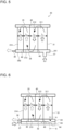
- respective partition plates 40 are provided as illustrated in Fig. 3 .
- the partition plates 40 are provided to partition the heat exchange body 31 into a plurality of regions in the horizontal direction.
- the partition plates 40 are provided such that refrigerant in each of the regions of the heat exchange body 31 flows in the opposite direction to the flow direction of refrigerant in an adjacent one of the regions that is adjacent to the above region, and is provided such that regarding the regions of the heat exchange body 31, the more downstream the region in the flow of refrigerant in the case where the heat exchanger 30 operates as a condenser (the flow of refrigerant being hereinafter referred to as "defrosting-operation refrigerant flow”), the smaller the flow passage cross-sectional area of the region.
- a single partition plate 40 is provided at each of the lower header 34 and the upper header 35. That is, the total number of the partition plates 40 is two. It should be noted that the number of the partition plates 40 is not limited to 2, but may be 1 or may be larger than or equal to 3. Furthermore, the heat exchange body 31 is partitioned by the partition plates 40 into three regions, that is, a first region 311, a second region 312, and a third region 313. In the flow of refrigerant in the defrosting operation, that is, the defrosting-operation refrigerant flow, the first region 311 is located most upstream, and the third region 313 is located most downstream.
- each of the regions of the heat exchange body 31 is provided such that in the region, refrigerant flows in the opposite direction to the flow direction of refrigerant that flows in the adjacent region. It should be noted that as indicated by arrows in Fig.
- the refrigerant flows through components and regions in the following order: the gas pipe 37, the lower header 34, the first region 311 of the heat exchange body 31, the upper header 35, the second region 312 of the heat exchange body 31, the lower header 34, the third region 313 of the heat exchange body 31, the upper header 35, and the liquid pipe 36.
- the third region 313 of the heat exchange body 31 has the smallest flow passage cross-sectional area, and a smallest number of flat tubes 38 are provided. That is, in the regions of the heat exchange body 31, the more downstream the region in the defrosting-operation refrigerant flow, the smaller the flow passage cross-sectional area of the region.
- a region located downstream in the defrosting-operation refrigerant flow is made to have a smaller flow passage cross-sectional area than a region located upstream in the defrosting-operation refrigerant flow, on the premise that in these regions, the refrigerant flows at the same flow rate, whereby the velocity of the refrigerant in the above region located downstream is higher than that in the above region located upstream.
- the heat exchanger 30 is configured such that in the case where the refrigerant flows upward in a region of the heat exchange body 31 that is located most downward when the heat exchanger 30 operates as a condenser, the flow of the refrigerant in the above region which is located most downstream and in which the refrigerant flows upward (which will be hereinafter referred to as "region Z") has a flooding constant C greater than 1.
- the flooding constant C is defined based on the flow rate of refrigerant that flows into the region Z in an intermediate load capacity (50% capacity) operation when the heat exchanger 30 operates as a condenser.
- J G is a dimensionless gas apparent velocity
- J L is a dimensionless liquid apparent velocity.
- J L U L ⁇ ⁇ L / 9.81 ⁇ D eq ⁇ L ⁇ ⁇ G 0.5
- Fig. 4 is a diagram illustrating the flow passage cross-sectional area of a flat tube 38 of the heat exchanger 30 according to Embodiment 1.
- ⁇ L is the liquid density [kg/m 3 ] of refrigerant
- ⁇ G is the gas density [kg/m 3 ] of refrigerant
- ⁇ L and ⁇ G are each a state quantity that can be calculated according to the kind and pressure of refrigerant that flows into the heat exchanger 30.
- U G is the gas apparent velocity [m/s]
- U L is the liquid apparent velocity [m/s].
- x is the quality of the refrigerant that flows into the region Z, and can be calculated, for example, based on the amount or performance of heat exchange at the heat exchanger 30. For example, assuming that the quality of the refrigerant varies from 1 to 0 between an inlet and an outlet of the heat exchanger 30, and the amount of heat exchange ⁇ the heat transfer area, x can be estimated by the ratio of the number of flat tubes 38 disposed in a region situated upstream of the region Z to the total number of flat tubes 38 of the heat exchanger 30.
- the heat exchanger 30 is configured such that in the case where the refrigerant flows upward through a region of the heat exchange body 31 that is located most downward, when the heat exchanger 30 operates as a condenser, the flow of the refrigerant in the region Z of the heat exchange body 31 has a flooding constant C greater than 1. It is therefore possible to more reliably reduce the probability that backflow of the refrigerant will occur, even in the case where the refrigerant flows upward through the region of the heat exchange body 31 that is located most downward when the heat exchanger 30 operates as a condenser.
- the heat exchanger 30 includes the heat exchange body 31 including the flat tubes 38 spaced from each other in the horizontal direction, the upper header 35 provided at the upper end of the heat exchange body 31, the lower header 34 provided at the lower end of the heat exchange body 31, and the partition plate 40 provided in at least one of the upper header 35 and the lower header 34 to partition the heat exchange body 31 into a plurality of regions in the horizontal direction.
- the partition plate 40 is provided to partition off the regions such that in each of the regions, refrigerant flows in the opposite direction to the flow direction of refrigerant in one of the regions that is adjacent to the above region, and also provided such that regarding the regions, the more downstream the region in the flow direction of the refrigerant in the case where the heat exchanger 30 operates as a condenser, the smaller the flow passage cross-sectional area of the region.
- the partition plate 40 is provided to partition the heat exchange body 31 into the regions such that in each of the regions, refrigerant flows in the opposite direction to the flow direction of refrigerant in the adjacent region, and also provided such that regarding the regions, the more downstream the region in the flow direction of the refrigerant in the case where the heat exchanger 30 operates as a condenser, the smaller the flow passage cross-sectional flow direction of the refrigerant in the case where the heat exchanger 30 operates as a condenser, the smaller the flow passage cross-sectional area of the region, it is possible to reduce lowering of the flow velocity of the refrigerant even when the ratio of the liquid phase of the refrigerant becomes higher, and is thus also possible to reduce the probability that backflow of the refrigerant will occur.
- the outdoor unit 10 according to Embodiment 1 includes the above heat exchanger 30.
- the outdoor unit 10 according to Embodiment 1 can obtain similar advantages to those of the heat exchanger 30.
- the air-conditioning apparatus 100 according to Embodiment 1 includes the above outdoor unit 10.
- the air-conditioning apparatus 100 according to Embodiment 1 can obtain similar advantages to those of the outdoor unit 10.
- Embodiment 2 components that are the same as or equivalent to those in Embodiment 1 will be denoted by the same reference signs, and configurations, etc., that are the same as those in Embodiment 1 and have already been described regarding Embodiment 1 will not be re-described.
- Fig. 5 is a front view schematically illustrating the flow of refrigerant in the heat exchanger 30 according to Embodiment 2 in the defrosting operation.
- outlined arrows and dashed arrows all indicate the flow of refrigerant.
- the heat exchanger 30 As illustrated in Fig. 5 , two partition plates 40 are provided in the lower header 34, and a single partition plate 40 is provided in the upper header 35. That is, a three partition plates 40 are provided in total. Furthermore, the heat exchange body 31 is partitioned by the partition plates 40 into four regions, that is, a first region 311, a second region 312, a third region 313, and a fourth region 314.
- the number of partition plates 40 is not limited to 3, but may be an odd number larger than or equal to 5.
- a portion of the lower header 34 which is located most upstream in the defrosting-operation refrigerant flow and which will be hereinafter referred to as "first portion 341" is connected to the refrigerant circuit of the air-conditioning apparatus 100 by the gas pipe 37.
- the first portion 341 of the lower header 34 causes, in the cooling operation, high-temperature and high-pressure gas refrigerant from the compressor 11 to flow into the heat exchanger 30, and causes, in the heating operation, low-temperature and low-pressure gas refrigerant subjected to heat exchange at the heat exchanger 30 to flow out therefrom to the refrigerant circuit.
- a portion of the lower header 34 which is located most downstream in the defrosting-operation refrigerant flow and which will be hereinafter referred to as "second portion 342" is connected to the refrigerant circuit of the air-conditioning apparatus 100 by the liquid pipe 36.
- the second portion 342 of the lower header 34 causes, in the heating operation, low-temperature and low-pressure two-phase refrigerant to flow into the heat exchanger 30 in the heating operation, and causes, in the cooling operation, low-temperature and high-pressure liquid refrigerant subjected to heat exchange at the heat exchanger 30 to flow out therefrom to the refrigerant circuit.
- each of the regions of the heat exchange body 31 is provided such that in the region, refrigerant flows in the opposite direction to that in one of the regions that is adjacent to the above region. It should be noted that in the defrosting operation, as indicated by arrows in Fig.
- the refrigerant flows through components and regions in the following order: the gas pipe 37, the lower header 34, the first region 311 of the heat exchange body 31, the upper header 35, the second region 312 of the heat exchange body 31, the lower header 34, the third region 313 of the heat exchange body 31, the upper header 35, the fourth region 314 of the heat exchange body 31, the lower header 34, and then the liquid pipe 36.
- the flow of the refrigerant in the fourth region 314 which is the most downward one of the regions of the heat exchange body 31 in the defrosting-operation refrigerant flow is the downward flow, whereby it is possible to reduce the probability with which backflow will occur, even in the case where the more downward the refrigerant, the higher the ratio of the liquid phase of the refrigerant. Furthermore, since a region located downstream has a smaller flow passage cross-sectional area than a region situated upstream, on the premise that in these regions, the refrigerant flows at the same flow rate, the flow velocity of refrigerant in the region situated downstream is higher than that in the region situated upstream.
- the outdoor unit 10 according to Embodiment 2 includes the above heat exchanger 30.
- the outdoor unit 10 according to Embodiment 2 can obtain similar advantages to those of the heat exchanger 30.
- the air-conditioning apparatus 100 according to Embodiment 2 includes the above outdoor unit 10.
- the air-conditioning apparatus 100 according to Embodiment 2 can obtain similar advantages to those of the above outdoor unit 10.
- Embodiment 3 components that are the same as or equivalent to those in Embodiment 2 will be denoted by the same reference signs, and configurations, etc., that are the same as those in Embodiment 2 and have already been described regarding Embodiment 2 will not be re-described.
- Fig. 6 is a front view schematically illustrating the defrosting-operation refrigerant flow at a heat exchanger 30 according to Embodiment 3.
- Fig. 7 is a cross-sectional view of the heat exchanger 30 that is taken along line A-A in Fig. 6 .
- outlined arrows and dashed arrows all indicate the flow of refrigerant.
- the heat exchanger 30 according to Embodiment 3 further includes an extension pipe 33 that extends in a longitudinal direction of the lower header 34.
- At least part of the extension pipe 33 is in contact with the lower header 34. Furthermore, the extension pipe 33 is provided below the lower header 34.
- the lower header 34 is connected to the liquid pipe 36, and the extension pipe 33 is connected to the gas pipe 37.
- an opening port 44 is formed at a contact position between the extension pipe 33 and the lower header 34, whereby the extension pipe 33 and the lower header 34 communicate with each other. This opening port 44 is formed below the first region 311 of the heat exchange body 31.
- the refrigerant flows through components and regions in the following order: the gas pipe 37, the extension pipe 33, the lower header 34, the first region 311 of the heat exchange body 31, the upper header 35, the second region 312 of the heat exchange body 31, the lower header 34, the third region 313 of the heat exchange body 31, the upper header 35, the fourth region 314 of the heat exchange body 31, the lower header 34, and then the liquid pipe 36.
- the extension pipe 33 is provided to extend in parallel with the lower header 34, and is at least partly in contact with the lower header 34. Furthermore, the extension pipe 33 is provided under the lower header 34. In such a manner, since the extension pipe 33 is at least partly in contact with the lower header 34, when high-temperature and high-pressure gas refrigerant flows through the extension pipe 33 in the defrosting operation, heat can be transferred from the extension pipe 33 to the lower header 34. Then, the heat transferred to the lower header 34 is further transferred to defrost water in the vicinity of the lower header 34, thereby raising the temperature of the defrost water.
- the extension pipe 33 since the extension pipe 33 is provided under the lower header 34, the extension pipe 33 does not obstruct the path of drainage of the defrost water, and it is therefore possible to prevent deterioration of the drainage.
- Fig. 8 is a cross-sectional view of a modification of the heat exchanger 30 that is taken along line A-A in Fig. 6 .
- the extension pipe 33 is provided separate from the lower header 34; however, the extension pipe 33 may be formed integrally with the lower header 34.
- a second partition plate 41 that divides the inside of the lower header 34 in the vertical direction is provided inside the lower header 34 as illustrated in Fig. 8 .
- the lower header 34 has an upper first flow passage 42 and a lower second flow passage 43.
- an upper portion of the lower header 34 is connected to the liquid pipe 36, and the first flow passage 42 communicates with the liquid pipe 36.
- a lower portion of the lower header 34 is connected to the gas pipe 37, and the second flow passage 43 communicates with the gas pipe 37. That is, a portion of the lower header 34 that forms the second flow passage 43 corresponds to the extension pipe 33 of Embodiment 3, and a portion of the lower header 34 that forms the second flow passage 43 corresponds to the lower header 34 of Embodiment 3.
- the second flow passage 43 of the lower header 34 is formed in parallel with the first flow passage 42 of the lower header 34, and the second flow passage 43 is formed adjacent to the first flow passage 42, with the second partition plate 41 interposed between the second flow passage 43 and the first flow passage 42. Therefore, when high-temperature and high-pressure gas refrigerant flows through the second flow passage 43 in the defrosting operation, heat can be transferred from the second flow passage 43 of the lower header 34 to the first flow passage 42 of the lower header 34 via the second partition plate 41.
- the heat transferred to the first flow passage 42 of the lower header 34 is further transferred to defrost water in the vicinity of the lower header 34, thus raising the temperature of the defrost water. Therefore, even when the heating operation is resumed after the defrosting operation ends, it is possible to reduce the probability that the defrost water in the vicinity of the lower header 34 will re-freeze. Thus, it is also possible to reduce deterioration of the heating performance and damage to the heat exchanger 30. Furthermore, since the second flow passage 43 of the lower header 34 is provided under the first flow passage 42 of the lower header 34, the second flow passage 43 does not obstruct the path of drainage of the defrost water, and it is therefore possible to prevent deterioration of the drainage.
- the heat exchanger 30 includes an extension pipe 33 through which the refrigerant flows out when the heat exchanger 30 operates as an evaporator and through which the refrigerant flows in when the heat exchanger 30 operates as a condenser.
- the extension pipe 33 is provided to extend in the longitudinal direction of the lower header 34 and is at least partly in contact with the lower header 34.
- the extension pipe 33 is at least partly in contact with the lower header 34, when high-temperature and high-pressure gas refrigerant flows through the extension pipe 33 in the defrosting operation, heat can be transferred from the extension pipe 33 to the lower header 34. Then, the heat transferred to the lower header 34 is further transferred to defrost water in the vicinity of the lower header 34, thereby raising the temperature of the defrost water. Therefore, even when the heating operation is resumed after the defrosting operation ends, it is possible to reduce the probability with which the defrost water in the vicinity of the lower header 34 will re-freeze. As a result, it is also possible to reduce deterioration of the heating performance and damage to the heat exchanger 30.
- the outdoor unit 10 according to Embodiment 3 includes the above heat exchanger 30.
- the outdoor unit 10 according to Embodiment 3 can obtain similar advantages to those of the heat exchanger 30.
- the air-conditioning apparatus 100 according to Embodiment 3 includes the above outdoor unit 10.
- the air-conditioning apparatus 100 according to Embodiment 3 can obtain similar advantages to those of the outdoor unit 10.
- Embodiment 4 components that are the same as or equivalent to those in Embodiment 2 will be denoted by the same reference signs, and configurations, etc., that are the same as those in Embodiment 2 and have already been described regarding Embodiment 2 will not be re-described.
- Fig. 9 is a front view schematically illustrating a bending region 50 of a heat exchanger 30 according to Embodiment 4.
- Fig. 10 is a plan view schematically illustrating the bending region 50 of the heat exchanger 30 according to Embodiment 4.
- the heat exchanger 30 may be subjected to bending, for example, in order to improve the heat exchange performance by densely mounting the heat exchanger 30 in the outdoor unit 10 and to make the outdoor unit 10 smaller.
- the bending is performed on the inside of the bending region 50 as illustrated in Figs. 9 and 10 .
- the partition plate 40 is provided in the bending region 50, the partition plate 40 is deformed when the heat exchanger 30 is subjected to the bending, thus deteriorating the heat exchange performance.
- the partition plate 40 is not provided in the bending region 50, but is provided outside the bending region 50.
- the upper header 35 and the lower header 34 have a bending region 50 where the heat exchanger 30 is subjected to the bending, and the partition plate 40 is provided in a region other than the bending region 50.
- the partition plate 40 is provided outside the bending region 50, whereby the partition plate 40 is not deformed even when the heat exchanger 30 is subjected to the bending. It is therefore possible to reduce the deterioration of the heat exchange performance while improving the heat exchange performance and reducing the size of the outdoor unit 10.
- the outdoor unit 10 according to Embodiment 4 includes the above heat exchanger 30.
- the outdoor unit 10 according to Embodiment 4 can obtain similar advantages to those of the heat exchanger 30.
- the air-conditioning apparatus 100 according to Embodiment 4 includes the above outdoor unit 10.
- the air-conditioning apparatus 100 according to Embodiment 4 can obtain similar advantages to those of the outdoor unit 10.
- Embodiment 5 components that are the same as or equivalent to those in Embodiment 2 will be denoted by the same reference signs, and configurations, etc., that are the same as those in Embodiment 2 and have already been described regarding Embodiment 2 will not be re-described.
- Fig. 11 is a front view schematically illustrating the defrosting-operation refrigerant flow at a heat exchanger 30 according to Embodiment 5.
- outlined arrows and dashed arrows all indicate the flow of refrigerant.
- the heat exchanger 30 has a plurality of heat exchange units.
- the heat exchanger 30 includes a first heat exchange unit 30a and a second heat exchange unit 30b.
- the first heat exchange unit 30a includes a first heat exchange body 31a, a first lower header 34a, and a first upper header 35a.
- the first heat exchange body 31a includes a plurality of flat tubes 38 and a plurality of fins 39.
- the first lower header 34a is provided at a lower end of the first heat exchange body 31a.
- the first upper header 35a is provided at an upper end of the first heat exchange body 31a.
- the second heat exchange unit 30b includes a second heat exchange body 31b, a second lower header 34b, and a second upper header 35b.
- the second heat exchange body 31b includes a plurality of flat tubes 38 and a plurality of fins 39.
- the second lower header 34b is provided at a lower end of the second heat exchange body 31b.
- the second upper header 35b is provided at an upper end of the second heat exchange body 31b.
- the first lower header 34a is connected to the refrigerant circuit of the air-conditioning apparatus 100 by the gas pipe 37.
- the first lower header 34a causes, in the cooling operation, high-temperature and high-pressure gas refrigerant from the compressor 11 to flow into the heat exchanger 30, and causes, in the heating operation, low-temperature and low-pressure gas refrigerant subjected to heat exchange at the heat exchanger 30 to flow out therefrom to the refrigerant circuit.
- the second lower header 34b is connected to the refrigerant circuit of the air-conditioning apparatus 100 by the liquid pipe 36.
- the second lower header 34b causes, in the heating operation, low-temperature and low-pressure two-phase refrigerant to flow into the heat exchanger 30, and causes, in the cooling operation, low-temperature and high-pressure liquid refrigerant subjected to heat exchange at the heat exchanger 30 to flow out therefrom to the refrigerant circuit.
- first upper header 35a and the second upper header 35b are connected to each other by a connecting pipe 60 to communicate with each other.
- the first lower header 34a and the second lower header 34b may be connected to each other by the connecting pipe 60 to communicate with each other.
- the gas pipe 37 is connected to the first upper header 35a
- the liquid pipe 36 is connected to the second lower header 34b.
- partition plates 40 are provided in the second heat exchange unit 30b.
- respective partition plates 40 are provided in the second lower header 34b and the second upper header 35b. That is, the total number of partition plates 40 is two.
- the second heat exchange body 31b is partitioned by the partition plates 40 into three regions, namely a first region 31b1, a second region 31b2, and a third region 31b3.
- the number of partition plates 40 is not limited to 2, but may be 1 or may be larger than or equal to 3. It should be noted that in the first heat exchange unit 30a, no partition plate 40 is provided.
- the refrigerant flows upward, that is, the flow of the refrigerant is the upward flow
- the refrigerant flows downward, that is, the flow of the refrigerant is the downward flow.
- the refrigerant flows upward. Therefore, each of the regions of the heat exchange body 31 is provided such that in the region, the refrigerant flows in the opposite direction to the flow direction of the refrigerant in one of the regions that is adjacent to the above region.
- the refrigerant flows through components and regions in the following order: the gas pipe 37, the first lower header 34a, the first heat exchange body 31a, the first upper header 35a, the connecting pipe 60, a first region 35b1 of the second upper header 35b, the first region 31b1 of the second heat exchange body 31b, a first flow passage 34b1 of the second lower header 34b, the second region 31b2 of the second heat exchange body 31b, a second region 35b2 of the second upper header 35b, the third region 31b3 of the second heat exchange body 31b, a second flow passage 34b2 of the second lower header 34b, and then the liquid pipe 36.
- the above regions that is, the first heat exchange body 31a and the regions of the second heat exchange body 31b, are provided such that the most downstream the region in the defrosting-operation refrigerant flow, the smaller the flow passage cross-sectional area of the region.
- the flow passage cross-sectional area is made smaller than that of a region located upstream, on the premise that in these regions, the refrigerant flows at the same flow rate, whereby the flow velocity of the refrigerant in the region located downstream can be higher than that in the region located upstream. It is therefore possible to reduce the probability with which backflow of the refrigerant will occur, even in the case where the more downstream the refrigerant, the higher the ratio of the liquid phase of the refrigerant, and is also possible to reduce deterioration of the defrosting performance which would be caused by the backflow of the refrigerant.
- the heat exchanger 30 is formed to include the first heat exchange unit 30a and the second heat exchange unit 30b, and the first heat exchange unit 30a and the second heat exchange unit 30b are connected by the connecting pipe 60, whereby the heat exchanger 30 can be easily subjected to the bending. Furthermore, since the first heat exchange unit 30a and the second heat exchange unit 30b are connected to each other, it suffices that the gas pipe 37 is connected only to a header of either the first heat exchange unit 30a or the second heat exchange unit 30b. It is therefore possible to reduce the space for pipe arrangement, and improve the heat exchange performance by densely mounting the heat exchanger 30 in the outdoor unit 10.
- the heat exchanger 30 may include three or more heat exchange units.
- the upper headers or lower headers of adjacent ones of the heat exchange units are connected to each other by the connecting pipe 60, and the adjacent heat exchange units communicate with each other through the upper headers or the lower headers.
- the heat exchange body 31 includes a first heat exchange body 31a and a second heat exchange body 31b.
- the upper header 35 includes a first upper header 35a provided at an upper end of the first heat exchange body 31a and a second upper header 35b provided at an upper end of the second heat exchange body 31b.
- the lower header 34 includes a first lower header 34a provided at a lower end of the first heat exchange body 31a and a second lower header 34b provided at a lower end of the second heat exchange body 31b.
- the first upper header 35a and the second upper header 35b or the first lower header 34a and the second lower header 34b are connected to each other by the connecting pipe 60 to communicate with each other.
- the heat exchanger 30 since the first upper header 35a and the second upper header 35b or the first lower header 34a and the second lower header 34b are connected to each other by the connecting pipe 60 to communicate with each other, the heat exchanger 30 can be easily subjected to the bending. Furthermore, since the first heat exchange unit 30a and the second heat exchange unit 30b are connected to each other, it suffices that the gas pipe 37 is connected only to a header of either the first heat exchange unit 30a or the second heat exchange unit 30b. It is therefore possible to reduce the space for pipe arrangement, and improve the heat exchange performance by densely mounting the heat exchanger 30 in the outdoor unit 10.
- the outdoor unit 10 according to Embodiment 5 includes the above heat exchanger 30.
- the outdoor unit 10 according to Embodiment 5 can obtain similar advantages to those of the heat exchanger 30.
- the air-conditioning apparatus 100 according to Embodiment 5 includes the above outdoor unit 10.
- the air-conditioning apparatus 100 according to Embodiment 5 can obtain similar advantages to those of the outdoor unit 10.
- Embodiment 6 components that are the same as or equivalent to those in Embodiment 5 will be denoted by the same reference signs, and configurations, etc., that are the same as those in Embodiment 5 and have already been described regarding Embodiment 2 will not be re-described.
- Fig. 12 is a front view schematically illustrating the defrosting-operation refrigerant flow at a heat exchanger 30 according to Embodiment 6.
- the first heat exchange body 31a and the second heat exchange body 31b have different lengths in the vertical direction, and the first heat exchange body 31a is longer than the second heat exchange body 31b. Furthermore, the first heat exchange body 31a and the second heat exchange body 31b are provided at the same level, or the first heat exchange body 31a is provided at a higher level than the second heat exchange body 31b.
- first upper header 35a and the second upper header 35b are connected to each other by a connecting pipe 60 to communicate with each other.
- the refrigerant flows downward or in the horizontal direction in the connecting pipe 60. It is therefore possible to reduce the probability with which backflow will occur that would do if the refrigerant flows upward in the connecting pipe 60, and also to reduce deterioration of the defrosting performance which would be caused by backflow of the refrigerant.
- the heat exchanger 30 according to Embodiment 6 includes two heat exchange units; however, the number of heat exchange units in the heat exchanger 30 is not limited to two.
- the heat exchanger 30 may include three or more heat exchange units.
- the upper headers or lower headers of adjacent ones of the heat exchange units are connected to each other by a connecting pipe 60, and the adjacent heat exchange units communicate with each other through the upper headers or the lower headers; and also in the defrosting-operation refrigerant flow, the refrigerant flows downward or in the horizontal direction through each connecting pipe 60.
- the first heat exchange body 31a and the second heat exchange body 31b have different lengths, and when the heat exchanger 30 operates as a condenser, the refrigerant flows downward or in the horizontal direction through the connecting pipe 60.
- the heat exchanger 30 when the heat exchanger 30 operates as a condenser, in the connecting pipe 60, the refrigerant flows downward or horizontally. It is therefore possible to reduce the probability with which backflow will occur that would do if the refrigerant flows upward in the connecting pipe 60, and also to reduce deterioration of the defrosting performance which would be caused by backflow of the refrigerant.
- the outdoor unit 10 according to Embodiment 6 includes the above heat exchanger 30.
- the outdoor unit 10 according to Embodiment 6 can obtain similar advantages to those of the heat exchanger 30.
- the air-conditioning apparatus 100 according to Embodiment 6 includes the above outdoor unit 10.
- the air-conditioning apparatus 100 according to Embodiment 6 can obtain similar advantages to those of the outdoor unit 10.
- Embodiment 7 components that are the same as or equivalent to those in any of Embodiments 1 to 6 will be denoted by the same reference signs, and configurations, etc., that are the same as those in any of Embodiments 1 to 6 and have already been described regarding Embodiments 1 to 6 will not be re-described.
- Fig. 13 is a perspective view schematically illustrating related components of a heat exchanger 30 according to Embodiment 7.
- the heat exchanger 30 includes a plurality of flat tubes 38 and a plurality of corrugated fins 39a.
- Each of the corrugated fins 39a is formed in a corrugated shape and has a plurality of apices 390, and each of the apices 390 is in surface contact with a flat surface of an associated adjacent one of the flat tubes 38, except for an end of the apex 390 that projects upstream in the flow direction of air (hereinafter referred to as "first direction") in the space between associated two flat tubes 38.
- first direction the flow direction of air
- the corrugated fin 39a is made, for example, of a plate material of an aluminum alloy. Moreover, a brazing filler metal layer is stacked on a surface of the plate material, and the brazing filler metal layer is formed, for example, of a brazing filler metal containing Al-Si based aluminum. Furthermore, the plate material has a plate thickness of approximately 50 to 200 ⁇ m.
- the corrugated fin 39a has fin surfaces 350 each of which is located between associated ones of the apices 390 that are adjacent in a direction in which the flat tubes 38 are arranged (which will be hereinafter referred to as "second direction") of the flat tubes 38, and the fin surfaces 350 are arranged in a height direction. Furthermore, each of the fin surfaces 350 has louvers 360 and a drainage slit 370.
- the louvers 360 are arranged in the first direction at the fin surface 350. That is, the louvers 360 are arranged in the flow direction of air.
- the louvers 360 are formed by cutting and raising parts of the fin surface 350. Also, by cutting up parts of the fin surface 350, slits 360a are formed in positions associated with the louvers 360 to allow air to pass through the slits 360a.
- the louvers 360 serve to guide air that passes through the slits 360a.
- the fin surfaces 350 have drainage slits 370 each of which is formed close to a central portion of an associated one of the fin surfaces 350 in the first direction, and each of which allows water on the fin surface 350 to be let out.
- the drainage slits 370 each have a rectangle extending in the second direction.
- the drainage slits 370 of ones of the fin surfaces 350 that are adjacent to each other at least in the height direction are located such that central positions of the above drainage slits 370 in the second direction are displaced from each other, and the positions of ends of the above drainage slits 370 are different from each other in the second direction.
- the temperatures of the surfaces of the flat tubes 38 and the corrugated fins 39a are lower than that of air that passes through the heat exchanger 30. Therefore, moisture in the air condenses on the surfaces of the flat tubes 38 and the corrugated fins 39a, thereby generating condensed water 380.
- Condensed water 380 generated on each of the fin surfaces 350 of each of the corrugated fins 39a flows through an associated drainage slit 370 and falls onto an associated lower fin surface 350.
- the condensed water 380 in a region where the amount of the condensed water 380 is large, the condensed water 380 easily flows over the fin surface 350, and thus also easily falls onto the lower fin surface 350 through the drainage slit 370.
- the condensed water 380 is easily retained and stay on the above fin surface 350, and does not easily flow over the fin surface 350.
- Fig. 14 is a front view schematically illustrating the heat exchanger 30 according to Embodiment 7.
- Fig. 15 is a diagram for explanation of positional relationships between drainage slits 370 in fin surfaces 350 of corrugated fins 39a as illustrated in Fig. 14 . It should be noted that (a) to (e) in Fig. 15 illustrate fin surfaces 350 located at positions (a) to (e) in Fig. 14 , respectively.
- the drainage slits 370 of ones of the fin surfaces 350 that are adjacent to each other at least in the height direction are located such that the central positions of the above drainage slits 370 in the second direction are displaced from each other, and the positions of the ends of the above drainage slits 370 are different from each other in the second direction.
- the drainage slits 370 of the fin surfaces 350 of each of the corrugated fins 39a are provided such that drainage slits 370 whose central positions in the second direction are the same as each other are periodically located in the corrugated fin 39a.
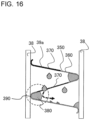
- Fig. 16 is a diagram for explanation of the flow of condensed water 380 on surfaces of a corrugated fin 39a in the heat exchanger 30 according to Embodiment 7.
- An apex 390 of the corrugated fin 39a that is joined to a flat tube 38 is formed by bending the corrugated fin 39a, and at the apex 390, the distance between fin surfaces 350 is short.
- condensed water 380 at the apex 390 is easily retained and stay at the apex 390 by surface tension.
- an end of a drainage slit 370 in the second direction can be provided at or near the apex 390.
- the fin surfaces 350 have respective drainage slits 370 for drainage of water, and positions of ends of the drainage slits 370 formed in ones of the fin surfaces 350 that are adjacent to each other in the height direction are different from each other in an arrangement direction of the flat tubes 38 in which they are arranged.
- condensed water 380 having fallen from an end of a drainage slit 370 in each fin surface 350 in the arrangement direction of the flat tubes 38 falls onto a subsequent lower fin surface 350. Then, the condensed water 380 that has fallen onto the subsequent lower fin surface 350 joins condensed water 380 retained on the lower fin surface 350, whereby those condensed water 380 is combined, the amount of the combined condensed water 380 increases, and the combined condensed water 380 easily flows and fall onto a further lower in surface 350 through an associated drainage slit 370. Thus, the amount of the above condensed water 380 retained on the fin surface 350 decreases. It is therefore possible to efficiently drain water, and reduce the deterioration of the defrosting operation.
Landscapes
- Engineering & Computer Science (AREA)
- Physics & Mathematics (AREA)
- Thermal Sciences (AREA)
- Mechanical Engineering (AREA)
- General Engineering & Computer Science (AREA)
- Geometry (AREA)
- Heat-Exchange Devices With Radiators And Conduit Assemblies (AREA)
- Other Air-Conditioning Systems (AREA)
- Details Of Heat-Exchange And Heat-Transfer (AREA)
Abstract
Description
- The present disclosure relates to a heat exchanger including a plurality of flat tubes, an outdoor unit including the heat exchanger, and an air-conditioning apparatus including the outdoor unit.
- A given existing heat exchanger includes a plurality of flat tubes extending in a vertical direction and spaced from each other in a horizontal direction, a plurality of fins which are each connected between associated adjacent ones of the flat tubes and which transfer heat to the flat tubes, and headers provided at upper and lower ends of the flat tubes (see, for example, Patent Literature 1).
- The heat exchanger of
Patent Literature 1 is provided in an outdoor unit of an air-conditioning apparatus that is capable of both cooling operation and heating operation. In the case where the heating operation is performed in a low-temperature environment in which an outdoor air temperature is low and the surface temperature of the heat exchanger is lower than or equal to 0 degrees C, frost forms on the heat exchanger. Thus, when the amount of the frost that forms on the heat exchanger reaches a certain amount or more, a defrosting operation of causing the frost on a surface of the heat exchanger to melt is performed. In the defrosting operation, high-temperature and high-pressure gas refrigerant is caused to flow into the flat tubes though one of the headers, to thereby remove the frost. - Patent Literature 1:
Japanese Unexamined Patent Application Publication No. 2018-96638 - In such an existing heat exchanger as described in
Patent Literature 1, in the defrosting operation, as refrigerant that has flowed into the flat tubes from a header flows farther, the refrigerant is further cooled, and the more downward the flowing refrigerant, the higher the ratio of the liquid phase of the refrigerant. Then, the higher the ratio of liquid phase of the refrigerant, the lower the velocity of the refrigerant, as a result of which the refrigerant more easily flows backward. If the refrigerant flows backward, the defrosting performance is deteriorated. - The present disclosure is applied to solve the above problem, and relates to a heat exchanger that reduces the probability with which refrigerant will flow backward, an outdoor unit including the heat exchanger, and an air-conditioning apparatus including the outdoor unit.
- A heat exchanger includes: a heat exchange body having a plurality of flat tubes arranged and spaced from each other in a horizontal direction; an upper header provided at an upper end of the heat exchange body; a lower header provided at a lower end of the heat exchange body; and a partition plate provided in at least one of the upper and lower headers to partition the heat exchange body into a plurality of regions in a horizontal direction. The partition plate is provided such that in each of the regions, refrigerant flows in the opposite direction to the flow direction of the refrigerant in an adjacent one of the regions, and is provided such that regarding the regions, the more downward the region in the flow of the refrigerant when the heat exchanger operates as a condenser, the smaller a flow passage cross-sectional area of the region.
- Furthermore, an outdoor unit of an air-conditioning apparatus according to another embodiment of the present disclosure includes the heat exchanger described above.
- Furthermore, an air-conditioning apparatus according to still another embodiment of the present disclosure includes the outdoor unit described above.
- In the heat exchanger according to the embodiment of the present disclosure, the outdoor unit including the heat exchanger, and the air-conditioning apparatus including the outdoor unit, the partition plate is provided such that in each of the regions of the heat exchange body, refrigerant flows in the opposite direction to the flow direction of refrigerant in an adjacent one of the regions, and is provided such that regarding the regions of the heat exchange body, the more downstream a region in the flow of refrigerant in the case where the heat exchanger operates as a condenser, the smaller the flow passage cross-sectional area of the region. In such a manner, since regarding the regions, the more downstream a region in the flow of refrigerant in the case where the heat exchanger operates as a condenser, the smaller the flow passage cross-sectional area of the region, it is possible to reduce lowering of the flow velocity of the refrigerant, even when the ratio of the liquid phase of the refrigerant becomes higher, and thus reduce the probability that backflow of the refrigerant will occur.
-
- [
Fig. 1] Fig. 1 is a refrigerant circuit diagram of an air-conditioning apparatus including a heat exchanger according toEmbodiment 1. - [
Fig. 2] Fig. 2 is a perspective view of the heat exchanger according toEmbodiment 1. - [
Fig. 3] Fig. 3 is a front view schematically illustrating a defrosting-operation refrigerant flow at the heat exchanger according toEmbodiment 1. - [
Fig. 4] Fig. 4 is a diagram illustrating the flow passage cross-sectional area of a flat tube of the heat exchanger according toEmbodiment 1. - [
Fig. 5] Fig. 5 is a front view schematically illustrating the defrosting-operation refrigerant flow at a heat exchanger according to Embodiment 2. - [
Fig. 6] Fig. 6 is a front view schematically illustrating the defrosting-operation refrigerant flow at a heat exchanger according to Embodiment 3. - [
Fig. 7] Fig. 7 is a cross-sectional view of the heat exchanger that is taken along line A-A inFig. 6 . - [
Fig. 8] Fig. 8 is a cross-sectional view of a modification of the heat exchanger that is taken along line A-A inFig. 6 . - [
Fig. 9] Fig. 9 is a front view schematically illustrating a bending region of a heat exchanger according to Embodiment 4. - [
Fig. 10] Fig. 10 is a plan view schematically illustrating the bending region of the heat exchanger according to Embodiment 4. - [
Fig. 11] Fig. 11 is a front view schematically illustrating the defrosting-operation refrigerant flow at a heat exchanger according to Embodiment 5. - [
Fig. 12] Fig. 12 is a front view schematically illustrating the defrosting-operation refrigerant flow at a heat exchanger according to Embodiment 6. - [
Fig. 13] Fig. 13 is a perspective view schematically illustrating related components of a heat exchanger according to Embodiment 7. - [
Fig. 14] Fig. 14 is a front view schematically illustrating the heat exchanger according to Embodiment 7. - [
Fig. 15] Fig. 15 is a diagram for explanation of positional relationships between drainage slits in fin surfaces of a corrugated fin as illustrated inFig. 14 . - [
Fig. 16] Fig. 16 is a diagram for explanation of the flow of condensed water on surfaces of a corrugated fin of the heat exchanger according to Embodiment 7. - The embodiments of the present disclosure will be described with reference to the drawings. This description, however, is not limiting. Furthermore, in each of references which will be referred to below, relationships in size between components may be different from actual ones.
-
Fig. 1 is a refrigerant circuit diagram of an air-conditioning apparatus 100 including aheat exchanger 30 according toEmbodiment 1. InFig. 1 , solid arrows indicate the flow of refrigerant during cooling operation, and dashed arrows indicate the flow of refrigerant during heating operation. - As illustrated in
Fig. 1 , theheat exchanger 30 according to Embodiment 1 is provided in anoutdoor unit 10 of an air-conditioning apparatus 100 that includes theoutdoor unit 10 and anindoor unit 20. Theoutdoor unit 10 includes acompressor 11, aflow switching device 12, and afan 13 in addition to theheat exchanger 30. Theindoor unit 20 includes anexpansion device 21, anindoor heat exchanger 22, and anindoor fan 23. - The air-
conditioning apparatus 100 includes a refrigerant circuit in which thecompressor 11, theflow switching device 12, theheat exchanger 30, theexpansion device 21, and theindoor heat exchanger 22 are connected by refrigerant pipes and refrigerant is circulated. The air-conditioning apparatus 100 is capable of performing both the cooling operation and the heating operation. The operation of the air-conditioning apparatus 100 is switched to one of the cooling operation and the heating operation by a switching operation of theflow switching device 12. - The
compressor 11 sucks low-temperature and low-pressure refrigerant, compresses the sucked refrigerant to change it into high-temperature and high-pressure refrigerant, and discharges the high-temperature and high-pressure refrigerant. Thecompressor 11 is, for example, an inverter compressor whose capacity is the rate of delivery per unit time and is controlled by varying an operating frequency. - The
flow switching device 12 is, for example, a four-way valve, and performs switching between the cooling operation and the heating operation by switching the flow direction of refrigerant. In order that the cooling operation be performed, the state of theflow switching device 12 is switched to a state indicated by solid lines inFig. 1 , whereby a discharge side of thecompressor 11 is connected to theheat exchanger 30. In contrast, in order that the heating operation be performed, the state of theflow switching device 12 is switched to a state indicated by dashed lines inFig. 1 , whereby the discharge side of thecompressor 11 is connected to theindoor heat exchanger 22. - The
heat exchanger 30 causes heat exchange to be performed between outdoor air and refrigerant. In the cooling operation, theheat exchanger 30 operates as a condenser that condenses the refrigerant by causing the refrigerant to transfer heat to the outdoor air. Furthermore, in the heating operation, theheat exchanger 30 operates as an evaporator that evaporates the refrigerant and cool the outdoor air with the heat of vaporization which is required for evaporation of the refrigerant. - The
fan 13 supplies outdoor air to theheat exchanger 30. The amount of air that is sent from thefan 13 to theheat exchanger 30 is adjusted under a control of the rotation speed of thefan 13. - The
expansion device 21 is, for example, an electronic expansion valve whose opening degree can be adjusted. The opening degree of theexpansion device 21 is adjusted, thereby controlling the pressure of refrigerant that flows into theheat exchanger 30 or theindoor heat exchanger 22. InEmbodiment 1, theexpansion device 21 is provided in theindoor unit 20; however, theexpansion device 21 may be provided in theoutdoor unit 10. The place of installation of theexpansion device 21 is not limited. - The
indoor heat exchanger 22 causes heat exchange to be performed between indoor air and refrigerant. In the cooling operation, theindoor heat exchanger 22 operates as an evaporator that evaporates the refrigerant and cool the indoor air with the heat of vaporization that is required for evaporation of the refrigerant. In the heating operation, theindoor heat exchanger 22 operates as a condenser that causes the heat of the refrigerant to be transferred to the indoor air, thereby condensing the refrigerant. - The
indoor fan 23 supplies indoor air to theindoor heat exchanger 22. The amount of air that is sent from theindoor fan 23 to theindoor heat exchanger 22 is adjusted under a control of the rotation speed of theindoor fan 23. -
Fig. 2 is a perspective view of theheat exchanger 30 according toEmbodiment 1. - As illustrated in
Fig. 2 , theheat exchanger 30 includes aheat exchange body 31 including a plurality offlat tubes 38 and a plurality offins 39. Theflat tubes 38 are arranged and spaced from each other in parallel in a horizontal direction, thereby enabling a wind generated by thefan 13 to flow, and theflat tubes 38 also extend in a vertical direction to allow refrigerant to flow in the vertical direction in theflat tubes 38. Thefins 39 are each connected between associated adjacent ones of theflat tubes 38, and transfer heat to theseflat tubes 38. It should be noted that thefins 39 are provided to improve the efficiency of heat exchange between air and refrigerant. For example, corrugated fins are used as thefins 39; however, thefins 39 are not limited to the corrugated fins. Thefins 39 may be omitted, since air and refrigerant exchange heat with each other at surfaces of theflat tubes 38. - At a lower end of the
heat exchange body 31, alower header 34 is provided. In thelower header 34, lower ends of theflat tubes 38 of theheat exchange body 31 are directly inserted. Furthermore, at an upper end of theheat exchange body 31, anupper header 35 is provided. In theupper header 35, upper ends of theflat tubes 38 of theheat exchange body 31 are directly inserted. - The
lower header 34 is connected to the refrigerant circuit of the air-conditioning apparatus 100 via a gas pipe 37 (seeFig. 3 , which will be referred later), and will also be referred to as "gas header". In the cooling operation, thelower header 34 causes high-temperature and high-pressure gas refrigerant from thecompressor 11 to flow into theheat exchanger 30, and in the heating operation, causes low-temperature and low-pressure gas refrigerant subjected to heat exchange at theheat exchanger 30 to flow out therefrom to the refrigerant circuit. - The
upper header 35 is connected to the refrigerant circuit of the air-conditioning apparatus 100 via a liquid pipe 36 (seeFig. 3 ), and will also be referred to as "liquid header". In the heating operation, theupper header 35 causes low-temperature and low-pressure two-phase refrigerant to flow into theheat exchanger 30, and in the cooling operation, causes low-temperature and high-pressure liquid refrigerant subjected to heat exchange at theheat exchanger 30 to flow out therefrom to the refrigerant circuit. - The
flat tubes 38, thefins 39, thelower header 34, and theupper header 35 are all made of aluminum, and are joined together by brazing. - High-temperature and high-pressure gas refrigerant discharged from the
compressor 11 flows into theheat exchanger 30 via theflow switching device 12. After having flowed into theheat exchanger 30, the high-temperature and high-pressure gas refrigerant condenses while transferring heat to outdoor air taken in by thefan 13, in heat exchange with the outdoor air, and as a result, changes into low-temperature and high-pressure liquid refrigerant, which then flows out of theheat exchanger 30. After having flowed out of theheat exchanger 30, the low-temperature and high-pressure liquid refrigerant is decompressed by theexpansion device 21 to change into low-temperature and low-pressure two-phase gas-liquid refrigerant, and the low-temperature and low-pressure two-phase gas-liquid refrigerant then flows into theindoor heat exchanger 22. After having flowed into theindoor heat exchanger 22, the low-temperature and low-pressure two-phase gas-liquid refrigerant evaporates while receiving heat from indoor air taken in by theindoor fan 23, in heat exchange with the indoor air, and also cooling the indoor air, and as a result, changes into low-temperature and low-pressure gas refrigerant, and the low-temperature and low-pressure gas refrigerant then flows out of theindoor heat exchanger 22. After having flowed out of theindoor heat exchanger 22, the low-temperature and low-pressure gas refrigerant is sucked into thecompressor 11 to change back into high-temperature and high-pressure gas refrigerant. - High-temperature and high-pressure gas refrigerant discharged from the
compressor 11 flows into theindoor heat exchanger 22 via theflow switching device 12. After having flowed into theindoor heat exchanger 22, the high-temperature and high-pressure gas refrigerant condenses while transferring heat to indoor air taken in by theindoor fan 23, in heat exchange with the indoor air, and thus heating the indoor air, and as a result, changes into low-temperature and high-pressure liquid refrigerant, and the low-temperature and high-pressure liquid refrigerant then flows out of theindoor heat exchanger 22. After having flowed out of theindoor heat exchanger 22, the low-temperature and high-pressure liquid refrigerant is decompressed by theexpansion device 21 to change into low-temperature and low-pressure two-phase gas-liquid refrigerant, and the low-temperature and low-pressure two-phase gas-liquid refrigerant then flows into theheat exchanger 30. After having flowed into theheat exchanger 30, the low-temperature and low-pressure two-phase gas-liquid refrigerant evaporates while receiving heat from outdoor air taken in by thefan 13, in heat exchange with the outdoor air, and as a result, changes into low-temperature and low-pressure gas refrigerant, and the low-temperature and low-pressure gas refrigerant flows out of theheat exchanger 30. After having flowed out of theheat exchanger 30, the low-temperature and low-pressure gas refrigerant is sucked into thecompressor 11 to change back into high-temperature and high-pressure gas refrigerant. - In the case where the heating operation is performed in a low-temperature environment in which the surface temperatures of the
flat tubes 38 and thefins 39 drop to 0 degrees C or less, frost forms on theheat exchanger 30. When the amount of frost that forms on theheat exchanger 30 reaches a given amount or more, an air passage at theheat exchanger 30 through which a wind from thefan 13 passes is closed by the frost, as a result of which the performance of theheat exchanger 30 is deteriorated and a heating performance is also deteriorated. Thus, in the case where the heating performance is deteriorated, a defrosting operation of causing the frost on a surface of theheat exchanger 30 to melt is performed. - In the defrosting operation, the
fan 13 is stopped, and the state of theflow switching device 12 is switched to the same state as in the cooling operation, whereby high-temperature and high-pressure gas refrigerant flows into theheat exchanger 30. As a result, the frost adhering to theflat tubes 38 and thefins 39 melt. When the defrosting operation is started, the high-temperature and high-pressure gas refrigerant flows into each of theflat tubes 38 via thelower header 34. Then, the high-temperature refrigerant that has flowed into theflat tubes 38 causes the frost adhering to theflat tubes 38 and thefins 39 to melt and change into water. The water into which the frost melts and changes (hereinafter referred to as "defrost water") drains from and along theflat tubes 38 or thefins 39 toward a region located below theheat exchanger 30. When the adhering frost melts, the defrosting operation is ended, and the heating operation is resumed. - In the defrosting operation, refrigerant that has flowed from the
lower header 34 is further cooled as it flows through theflat tubes 38, such that the more downstream the flowing refrigerant, the higher the ratio of the liquid phase of the refrigerant. The higher the ratio of the liquid-phase of the refrigerant, the lower the velocity of the refrigerant, as a result of which the refrigerant more easily flows backward. In the related art, when the refrigerant flows backward, the defrosting performance is deteriorated. -
Fig. 3 is a front view schematically illustrating the flow of refrigerant in the defrosting operation at theheat exchanger 30 according toEmbodiment 1. InFig. 3 , outlined arrows and black dashed arrows all indicate flows of refrigerant. - In the
heat exchanger 30 according toEmbodiment 1, in thelower header 34 and theupper header 35,respective partition plates 40 are provided as illustrated inFig. 3 . Thepartition plates 40 are provided to partition theheat exchange body 31 into a plurality of regions in the horizontal direction. Furthermore, thepartition plates 40 are provided such that refrigerant in each of the regions of theheat exchange body 31 flows in the opposite direction to the flow direction of refrigerant in an adjacent one of the regions that is adjacent to the above region, and is provided such that regarding the regions of theheat exchange body 31, the more downstream the region in the flow of refrigerant in the case where theheat exchanger 30 operates as a condenser (the flow of refrigerant being hereinafter referred to as "defrosting-operation refrigerant flow"), the smaller the flow passage cross-sectional area of the region. - In
Embodiment 1, at each of thelower header 34 and theupper header 35, asingle partition plate 40 is provided. That is, the total number of thepartition plates 40 is two. It should be noted that the number of thepartition plates 40 is not limited to 2, but may be 1 or may be larger than or equal to 3. Furthermore, theheat exchange body 31 is partitioned by thepartition plates 40 into three regions, that is, afirst region 311, asecond region 312, and athird region 313. In the flow of refrigerant in the defrosting operation, that is, the defrosting-operation refrigerant flow, thefirst region 311 is located most upstream, and thethird region 313 is located most downstream. - Moreover, as illustrated in
Fig. 3 , in the first andthird regions heat exchange body 31, the refrigerant flows upward in the vertical direction, that is, the flow of the refrigerant is an upward flow, and in thesecond region 312 of theheat exchange body 31, the refrigerant flows downward in the vertical direction, that is, the flow of the refrigerant is a downward flow. Therefore, each of the regions of theheat exchange body 31 is provided such that in the region, refrigerant flows in the opposite direction to the flow direction of refrigerant that flows in the adjacent region. It should be noted that as indicated by arrows inFig. 3 , the refrigerant flows through components and regions in the following order: thegas pipe 37, thelower header 34, thefirst region 311 of theheat exchange body 31, theupper header 35, thesecond region 312 of theheat exchange body 31, thelower header 34, thethird region 313 of theheat exchange body 31, theupper header 35, and theliquid pipe 36. - Furthermore, L1 > L2 > L3, where L1, L2, and L3 are the lengths of the first, second, and
third regions heat exchange body 31 in the horizontal direction, respectively. Therefore, thefirst region 311 of theheat exchange body 31 has the largest flow passage cross-sectional area, and a largest number offlat tubes 38 are provided in thefirst region 311. Thethird region 313 of theheat exchange body 31 has the smallest flow passage cross-sectional area, and a smallest number offlat tubes 38 are provided. That is, in the regions of theheat exchange body 31, the more downstream the region in the defrosting-operation refrigerant flow, the smaller the flow passage cross-sectional area of the region. - In such a manner, in
Embodiment 1, a region located downstream in the defrosting-operation refrigerant flow is made to have a smaller flow passage cross-sectional area than a region located upstream in the defrosting-operation refrigerant flow, on the premise that in these regions, the refrigerant flows at the same flow rate, whereby the velocity of the refrigerant in the above region located downstream is higher than that in the above region located upstream. Therefore, even in the case where the more downstream the region, the higher the ratio of the liquid phase of the refrigerant in the region, it is possible to reduce the possibility with which back-flow of the refrigerant will occur, and also reduce deterioration of the defrosting performance that would be caused by the back-flow of the refrigerant. - Furthermore, the
heat exchanger 30 is configured such that in the case where the refrigerant flows upward in a region of theheat exchange body 31 that is located most downward when theheat exchanger 30 operates as a condenser, the flow of the refrigerant in the above region which is located most downstream and in which the refrigerant flows upward (which will be hereinafter referred to as "region Z") has a flooding constant C greater than 1. The flooding constant C is defined based on the flow rate of refrigerant that flows into the region Z in an intermediate load capacity (50% capacity) operation when theheat exchanger 30 operates as a condenser. - For example, according to a well-known Wallis formula, the flooding constant C is expressed by C = JG 0.5 + JL 0.5.
- JG is a dimensionless gas apparent velocity, and JL is a dimensionless liquid apparent velocity. JG and JL are expressed by the following equations:


-
Fig. 4 is a diagram illustrating the flow passage cross-sectional area of aflat tube 38 of theheat exchanger 30 according toEmbodiment 1. - Deq is an equivalent diameter [m] that is defined by the number N of
flat tubes 38 disposed in the region Z and the flow passage cross-sectional areas A1 (the total area of hatched areas as illustrated inFig. 4 ), and is calculated as Deq = [(4 × Aeq)/3.14]0.5. It should be noted that Aeq is calculated as Aeq = A1 × N. - ρL is the liquid density [kg/m3] of refrigerant, ρG is the gas density [kg/m3] of refrigerant, and ρL and ρG are each a state quantity that can be calculated according to the kind and pressure of refrigerant that flows into the
heat exchanger 30. - UG is the gas apparent velocity [m/s], and UL is the liquid apparent velocity [m/s]. UG is calculated as UG = (G × x)/ρG, and UL is calculated as UL = [G × (1 - x)]/ρL.
- G is calculated as G = M/Aeq, where G is the maximum velocity of flow [kg/m2s] of high-temperature and high-pressure gas refrigerant that flows into the
heat exchanger 30, and M is the maximum quantity of flow [kg/s] of the high-temperature and high-pressure gas refrigerant that flows into theheat exchanger 30. - x is the quality of the refrigerant that flows into the region Z, and can be calculated, for example, based on the amount or performance of heat exchange at the
heat exchanger 30. For example, assuming that the quality of the refrigerant varies from 1 to 0 between an inlet and an outlet of theheat exchanger 30, and the amount of heat exchange ∝ the heat transfer area, x can be estimated by the ratio of the number offlat tubes 38 disposed in a region situated upstream of the region Z to the total number offlat tubes 38 of theheat exchanger 30. For example, inEmbodiment 1, x can be defined as x = 1 - (the number of flat tubes in the first region + the number of flat tubes in the second region)/(the number of flat tubes in the first region + the number of flat tubes in the second region + the number of flat tubes in the third region). - As described above, the
heat exchanger 30 is configured such that in the case where the refrigerant flows upward through a region of theheat exchange body 31 that is located most downward, when theheat exchanger 30 operates as a condenser, the flow of the refrigerant in the region Z of theheat exchange body 31 has a flooding constant C greater than 1. It is therefore possible to more reliably reduce the probability that backflow of the refrigerant will occur, even in the case where the refrigerant flows upward through the region of theheat exchange body 31 that is located most downward when theheat exchanger 30 operates as a condenser. - As described above, the
heat exchanger 30 according toEmbodiment 1 includes theheat exchange body 31 including theflat tubes 38 spaced from each other in the horizontal direction, theupper header 35 provided at the upper end of theheat exchange body 31, thelower header 34 provided at the lower end of theheat exchange body 31, and thepartition plate 40 provided in at least one of theupper header 35 and thelower header 34 to partition theheat exchange body 31 into a plurality of regions in the horizontal direction. Thepartition plate 40 is provided to partition off the regions such that in each of the regions, refrigerant flows in the opposite direction to the flow direction of refrigerant in one of the regions that is adjacent to the above region, and also provided such that regarding the regions, the more downstream the region in the flow direction of the refrigerant in the case where theheat exchanger 30 operates as a condenser, the smaller the flow passage cross-sectional area of the region. - In the
heat exchanger 30 according toEmbodiment 1, thepartition plate 40 is provided to partition theheat exchange body 31 into the regions such that in each of the regions, refrigerant flows in the opposite direction to the flow direction of refrigerant in the adjacent region, and also provided such that regarding the regions, the more downstream the region in the flow direction of the refrigerant in the case where theheat exchanger 30 operates as a condenser, the smaller the flow passage cross-sectional flow direction of the refrigerant in the case where theheat exchanger 30 operates as a condenser, the smaller the flow passage cross-sectional area of the region, it is possible to reduce lowering of the flow velocity of the refrigerant even when the ratio of the liquid phase of the refrigerant becomes higher, and is thus also possible to reduce the probability that backflow of the refrigerant will occur. - Furthermore, the
outdoor unit 10 according toEmbodiment 1 includes theabove heat exchanger 30. Theoutdoor unit 10 according toEmbodiment 1 can obtain similar advantages to those of theheat exchanger 30. - Moreover, the air-
conditioning apparatus 100 according toEmbodiment 1 includes the aboveoutdoor unit 10. The air-conditioning apparatus 100 according toEmbodiment 1 can obtain similar advantages to those of theoutdoor unit 10. - Regarding Embodiment 2, components that are the same as or equivalent to those in
Embodiment 1 will be denoted by the same reference signs, and configurations, etc., that are the same as those inEmbodiment 1 and have already been described regardingEmbodiment 1 will not be re-described. -
Fig. 5 is a front view schematically illustrating the flow of refrigerant in theheat exchanger 30 according to Embodiment 2 in the defrosting operation. InFig. 5 , outlined arrows and dashed arrows all indicate the flow of refrigerant. - In the
heat exchanger 30 according to Embodiment 2, as illustrated inFig. 5 , twopartition plates 40 are provided in thelower header 34, and asingle partition plate 40 is provided in theupper header 35. That is, a threepartition plates 40 are provided in total. Furthermore, theheat exchange body 31 is partitioned by thepartition plates 40 into four regions, that is, afirst region 311, asecond region 312, athird region 313, and afourth region 314. However, the number ofpartition plates 40 is not limited to 3, but may be an odd number larger than or equal to 5. - A portion of the
lower header 34 which is located most upstream in the defrosting-operation refrigerant flow and which will be hereinafter referred to as "first portion 341" is connected to the refrigerant circuit of the air-conditioning apparatus 100 by thegas pipe 37. Thefirst portion 341 of thelower header 34 causes, in the cooling operation, high-temperature and high-pressure gas refrigerant from thecompressor 11 to flow into theheat exchanger 30, and causes, in the heating operation, low-temperature and low-pressure gas refrigerant subjected to heat exchange at theheat exchanger 30 to flow out therefrom to the refrigerant circuit. - A portion of the
lower header 34 which is located most downstream in the defrosting-operation refrigerant flow and which will be hereinafter referred to as "second portion 342" is connected to the refrigerant circuit of the air-conditioning apparatus 100 by theliquid pipe 36. Thesecond portion 342 of thelower header 34 causes, in the heating operation, low-temperature and low-pressure two-phase refrigerant to flow into theheat exchanger 30 in the heating operation, and causes, in the cooling operation, low-temperature and high-pressure liquid refrigerant subjected to heat exchange at theheat exchanger 30 to flow out therefrom to the refrigerant circuit. - Furthermore, as illustrated in
Fig. 5 , in the first andthird regions heat exchange body 31, the refrigerant flows upward, that is, the flow of the refrigerant is the upward flow, and in the second andfourth regions heat exchange body 31, the refrigerant flows downward, that is, the flow of the refrigerant is the downward flow. Therefore, each of the regions of theheat exchange body 31 is provided such that in the region, refrigerant flows in the opposite direction to that in one of the regions that is adjacent to the above region. It should be noted that in the defrosting operation, as indicated by arrows inFig. 5 , the refrigerant flows through components and regions in the following order: thegas pipe 37, thelower header 34, thefirst region 311 of theheat exchange body 31, theupper header 35, thesecond region 312 of theheat exchange body 31, thelower header 34, thethird region 313 of theheat exchange body 31, theupper header 35, thefourth region 314 of theheat exchange body 31, thelower header 34, and then theliquid pipe 36. - Furthermore, L1 > L2 > L3 > L4, where L1, L2, L3, and L4 are the lengths of the
first region 311, thesecond region 312, thethird region 313, and thefourth region 314 of theheat exchange body 31 in the horizontal direction, respectively. Therefore, of these regions, in thefirst region 311 of theheat exchange body 31, the number offlat tubes 38 provided is the largest, and the first region has the largest flow passage cross-sectional area; and in thefourth region 314 of theheat exchange body 31, the number offlat tubes 38 provided is the smallest, and thefourth region 314 has the smallest flow passage cross-sectional area. That is, regarding the regions of theheat exchange body 31, in the defrosting-operation refrigerant flow, the more downstream the region, the smaller the flow passage cross-sectional area of the region. - In such a manner, the flow of the refrigerant in the
fourth region 314 which is the most downward one of the regions of theheat exchange body 31 in the defrosting-operation refrigerant flow is the downward flow, whereby it is possible to reduce the probability with which backflow will occur, even in the case where the more downward the refrigerant, the higher the ratio of the liquid phase of the refrigerant. Furthermore, since a region located downstream has a smaller flow passage cross-sectional area than a region situated upstream, on the premise that in these regions, the refrigerant flows at the same flow rate, the flow velocity of refrigerant in the region situated downstream is higher than that in the region situated upstream. It is therefore possible to further reduce the probability with which backflow will occur, even in the case where the more downward the flowing refrigerant, the higher the ratio of the liquid phase of the refrigerant, and further reduce deterioration of the defrosting performance which would be caused by backflow of the refrigerant. - As described above, in the
heat exchanger 30 according to Embodiment 2, when theheat exchanger 30 operates as a condenser, the flow of refrigerant that flows in the most downward region is the downward flow. - In the
heat exchanger 30 according to Embodiment 2, when theheat exchanger 30 operates as a condenser, refrigerant that flows in the most downward region flows downward, whereby it is possible to reduce the probability with which backflow will occur, even in the case where the more downward the flowing refrigerant, the higher the ratio of the liquid phase of the refrigerant.. - Furthermore, the
outdoor unit 10 according to Embodiment 2 includes theabove heat exchanger 30. Theoutdoor unit 10 according to Embodiment 2 can obtain similar advantages to those of theheat exchanger 30. - Moreover, the air-
conditioning apparatus 100 according to Embodiment 2 includes the aboveoutdoor unit 10. The air-conditioning apparatus 100 according to Embodiment 2 can obtain similar advantages to those of the aboveoutdoor unit 10. - Regarding Embodiment 3, components that are the same as or equivalent to those in Embodiment 2 will be denoted by the same reference signs, and configurations, etc., that are the same as those in Embodiment 2 and have already been described regarding Embodiment 2 will not be re-described.
-
Fig. 6 is a front view schematically illustrating the defrosting-operation refrigerant flow at aheat exchanger 30 according to Embodiment 3.Fig. 7 is a cross-sectional view of theheat exchanger 30 that is taken along line A-A inFig. 6 . InFig. 6 , outlined arrows and dashed arrows all indicate the flow of refrigerant. - As illustrated in
Figs. 6 and7 , theheat exchanger 30 according to Embodiment 3 further includes anextension pipe 33 that extends in a longitudinal direction of thelower header 34. - At least part of the
extension pipe 33 is in contact with thelower header 34. Furthermore, theextension pipe 33 is provided below thelower header 34. Thelower header 34 is connected to theliquid pipe 36, and theextension pipe 33 is connected to thegas pipe 37. Furthermore, anopening port 44 is formed at a contact position between theextension pipe 33 and thelower header 34, whereby theextension pipe 33 and thelower header 34 communicate with each other. This openingport 44 is formed below thefirst region 311 of theheat exchange body 31. - In the defrosting operation, as indicated by arrows in
Fig. 6 , the refrigerant flows through components and regions in the following order: thegas pipe 37, theextension pipe 33, thelower header 34, thefirst region 311 of theheat exchange body 31, theupper header 35, thesecond region 312 of theheat exchange body 31, thelower header 34, thethird region 313 of theheat exchange body 31, theupper header 35, thefourth region 314 of theheat exchange body 31, thelower header 34, and then theliquid pipe 36. - In Embodiment 3, the
extension pipe 33 is provided to extend in parallel with thelower header 34, and is at least partly in contact with thelower header 34. Furthermore, theextension pipe 33 is provided under thelower header 34. In such a manner, since theextension pipe 33 is at least partly in contact with thelower header 34, when high-temperature and high-pressure gas refrigerant flows through theextension pipe 33 in the defrosting operation, heat can be transferred from theextension pipe 33 to thelower header 34. Then, the heat transferred to thelower header 34 is further transferred to defrost water in the vicinity of thelower header 34, thereby raising the temperature of the defrost water. Therefore, even when the heating operation is resumed after the defrosting operation ends, it is possible to reduce the probability with which the defrost water in the vicinity of thelower header 34 will re-freeze. As a result, it is possible to reduce deterioration of a heating performance and damage to theheat exchanger 30. Furthermore, since theextension pipe 33 is provided under thelower header 34, theextension pipe 33 does not obstruct the path of drainage of the defrost water, and it is therefore possible to prevent deterioration of the drainage. -
Fig. 8 is a cross-sectional view of a modification of theheat exchanger 30 that is taken along line A-A inFig. 6 . - In Embodiment 3, the
extension pipe 33 is provided separate from thelower header 34; however, theextension pipe 33 may be formed integrally with thelower header 34. In such a case, in the modification, asecond partition plate 41 that divides the inside of thelower header 34 in the vertical direction is provided inside thelower header 34 as illustrated inFig. 8 . Thus, thelower header 34 has an upperfirst flow passage 42 and a lowersecond flow passage 43. Moreover, an upper portion of thelower header 34 is connected to theliquid pipe 36, and thefirst flow passage 42 communicates with theliquid pipe 36. Furthermore, a lower portion of thelower header 34 is connected to thegas pipe 37, and thesecond flow passage 43 communicates with thegas pipe 37. That is, a portion of thelower header 34 that forms thesecond flow passage 43 corresponds to theextension pipe 33 of Embodiment 3, and a portion of thelower header 34 that forms thesecond flow passage 43 corresponds to thelower header 34 of Embodiment 3. - In such a manner, in the
heat exchanger 30 according to the modification of Embodiment 3, thesecond flow passage 43 of thelower header 34 is formed in parallel with thefirst flow passage 42 of thelower header 34, and thesecond flow passage 43 is formed adjacent to thefirst flow passage 42, with thesecond partition plate 41 interposed between thesecond flow passage 43 and thefirst flow passage 42. Therefore, when high-temperature and high-pressure gas refrigerant flows through thesecond flow passage 43 in the defrosting operation, heat can be transferred from thesecond flow passage 43 of thelower header 34 to thefirst flow passage 42 of thelower header 34 via thesecond partition plate 41. Then, the heat transferred to thefirst flow passage 42 of thelower header 34 is further transferred to defrost water in the vicinity of thelower header 34, thus raising the temperature of the defrost water. Therefore, even when the heating operation is resumed after the defrosting operation ends, it is possible to reduce the probability that the defrost water in the vicinity of thelower header 34 will re-freeze. Thus, it is also possible to reduce deterioration of the heating performance and damage to theheat exchanger 30. Furthermore, since thesecond flow passage 43 of thelower header 34 is provided under thefirst flow passage 42 of thelower header 34, thesecond flow passage 43 does not obstruct the path of drainage of the defrost water, and it is therefore possible to prevent deterioration of the drainage. - As described above, the
heat exchanger 30 according to Embodiment 3 includes anextension pipe 33 through which the refrigerant flows out when theheat exchanger 30 operates as an evaporator and through which the refrigerant flows in when theheat exchanger 30 operates as a condenser. Moreover, theextension pipe 33 is provided to extend in the longitudinal direction of thelower header 34 and is at least partly in contact with thelower header 34. - In the
heat exchanger 30 according to Embodiment 3, since theextension pipe 33 is at least partly in contact with thelower header 34, when high-temperature and high-pressure gas refrigerant flows through theextension pipe 33 in the defrosting operation, heat can be transferred from theextension pipe 33 to thelower header 34. Then, the heat transferred to thelower header 34 is further transferred to defrost water in the vicinity of thelower header 34, thereby raising the temperature of the defrost water. Therefore, even when the heating operation is resumed after the defrosting operation ends, it is possible to reduce the probability with which the defrost water in the vicinity of thelower header 34 will re-freeze. As a result, it is also possible to reduce deterioration of the heating performance and damage to theheat exchanger 30. - The
outdoor unit 10 according to Embodiment 3 includes theabove heat exchanger 30. Theoutdoor unit 10 according to Embodiment 3 can obtain similar advantages to those of theheat exchanger 30. - The air-
conditioning apparatus 100 according to Embodiment 3 includes the aboveoutdoor unit 10. The air-conditioning apparatus 100 according to Embodiment 3 can obtain similar advantages to those of theoutdoor unit 10. - Regarding Embodiment 4, components that are the same as or equivalent to those in Embodiment 2 will be denoted by the same reference signs, and configurations, etc., that are the same as those in Embodiment 2 and have already been described regarding Embodiment 2 will not be re-described.
-
Fig. 9 is a front view schematically illustrating a bendingregion 50 of aheat exchanger 30 according to Embodiment 4.Fig. 10 is a plan view schematically illustrating the bendingregion 50 of theheat exchanger 30 according to Embodiment 4. - The
heat exchanger 30 may be subjected to bending, for example, in order to improve the heat exchange performance by densely mounting theheat exchanger 30 in theoutdoor unit 10 and to make theoutdoor unit 10 smaller. In that case, the bending is performed on the inside of the bendingregion 50 as illustrated inFigs. 9 and 10 . Also, in this case, in the case where thepartition plate 40 is provided in the bendingregion 50, thepartition plate 40 is deformed when theheat exchanger 30 is subjected to the bending, thus deteriorating the heat exchange performance. In view of this point, in Embodiment 4, thepartition plate 40 is not provided in the bendingregion 50, but is provided outside the bendingregion 50. In such a manner, since thepartition plate 40 is provided outside the bendingregion 50, thepartition plate 40 is not deformed even when theheat exchanger 30 is subjected to the bending. It is therefore possible to reduce deterioration of the heat exchange performance while improving the heat exchange performance and reducing the size of theoutdoor unit 10. - As described above, in the
heat exchanger 30 according to Embodiment 4, theupper header 35 and thelower header 34 have a bendingregion 50 where theheat exchanger 30 is subjected to the bending, and thepartition plate 40 is provided in a region other than the bendingregion 50. - In the
heat exchanger 30 according to Embodiment 4, thepartition plate 40 is provided outside the bendingregion 50, whereby thepartition plate 40 is not deformed even when theheat exchanger 30 is subjected to the bending. It is therefore possible to reduce the deterioration of the heat exchange performance while improving the heat exchange performance and reducing the size of theoutdoor unit 10. - Furthermore, the
outdoor unit 10 according to Embodiment 4 includes theabove heat exchanger 30. Theoutdoor unit 10 according to Embodiment 4 can obtain similar advantages to those of theheat exchanger 30. - Furthermore, the air-
conditioning apparatus 100 according to Embodiment 4 includes the aboveoutdoor unit 10. The air-conditioning apparatus 100 according to Embodiment 4 can obtain similar advantages to those of theoutdoor unit 10. - Regarding Embodiment 5, components that are the same as or equivalent to those in Embodiment 2 will be denoted by the same reference signs, and configurations, etc., that are the same as those in Embodiment 2 and have already been described regarding Embodiment 2 will not be re-described.
-
Fig. 11 is a front view schematically illustrating the defrosting-operation refrigerant flow at aheat exchanger 30 according to Embodiment 5. InFig. 11 , outlined arrows and dashed arrows all indicate the flow of refrigerant. - As illustrated in
Fig. 11 , theheat exchanger 30 according to Embodiment 5 has a plurality of heat exchange units. Specifically, theheat exchanger 30 includes a firstheat exchange unit 30a and a secondheat exchange unit 30b. The firstheat exchange unit 30a includes a firstheat exchange body 31a, a firstlower header 34a, and a firstupper header 35a. The firstheat exchange body 31a includes a plurality offlat tubes 38 and a plurality offins 39. The firstlower header 34a is provided at a lower end of the firstheat exchange body 31a. The firstupper header 35a is provided at an upper end of the firstheat exchange body 31a. Furthermore, the secondheat exchange unit 30b includes a secondheat exchange body 31b, a secondlower header 34b, and a secondupper header 35b. The secondheat exchange body 31b includes a plurality offlat tubes 38 and a plurality offins 39. The secondlower header 34b is provided at a lower end of the secondheat exchange body 31b. The secondupper header 35b is provided at an upper end of the secondheat exchange body 31b. - The first
lower header 34a is connected to the refrigerant circuit of the air-conditioning apparatus 100 by thegas pipe 37. The firstlower header 34a causes, in the cooling operation, high-temperature and high-pressure gas refrigerant from thecompressor 11 to flow into theheat exchanger 30, and causes, in the heating operation, low-temperature and low-pressure gas refrigerant subjected to heat exchange at theheat exchanger 30 to flow out therefrom to the refrigerant circuit. - The second
lower header 34b is connected to the refrigerant circuit of the air-conditioning apparatus 100 by theliquid pipe 36. The secondlower header 34b causes, in the heating operation, low-temperature and low-pressure two-phase refrigerant to flow into theheat exchanger 30, and causes, in the cooling operation, low-temperature and high-pressure liquid refrigerant subjected to heat exchange at theheat exchanger 30 to flow out therefrom to the refrigerant circuit. - Furthermore, the first
upper header 35a and the secondupper header 35b are connected to each other by a connectingpipe 60 to communicate with each other. Instead of the firstupper header 35a and the secondupper header 35b, the firstlower header 34a and the secondlower header 34b may be connected to each other by the connectingpipe 60 to communicate with each other. In this case, in Embodiment 5, thegas pipe 37 is connected to the firstupper header 35a, and theliquid pipe 36 is connected to the secondlower header 34b. - Furthermore, in the second
heat exchange unit 30b,partition plates 40 are provided. To be more specific, in the secondlower header 34b and the secondupper header 35b,respective partition plates 40 are provided. That is, the total number ofpartition plates 40 is two. The secondheat exchange body 31b is partitioned by thepartition plates 40 into three regions, namely a first region 31b1, a second region 31b2, and a third region 31b3. However, the number ofpartition plates 40 is not limited to 2, but may be 1 or may be larger than or equal to 3. It should be noted that in the firstheat exchange unit 30a, nopartition plate 40 is provided. - Moreover, as illustrated in
Fig. 11 , in the first and third regions 31b1 and 31b3 of the secondheat exchange body 31b, the refrigerant flows upward, that is, the flow of the refrigerant is the upward flow, and in the second region 31b2 of the secondheat exchange body 31b, the refrigerant flows downward, that is, the flow of the refrigerant is the downward flow. Furthermore, in the firstheat exchange body 31a, the refrigerant flows upward. Therefore, each of the regions of theheat exchange body 31 is provided such that in the region, the refrigerant flows in the opposite direction to the flow direction of the refrigerant in one of the regions that is adjacent to the above region. It should be noted that in the defrosting operation, as indicated by arrows inFig. 11 , the refrigerant flows through components and regions in the following order: thegas pipe 37, the firstlower header 34a, the firstheat exchange body 31a, the firstupper header 35a, the connectingpipe 60, a first region 35b1 of the secondupper header 35b, the first region 31b1 of the secondheat exchange body 31b, a first flow passage 34b1 of the secondlower header 34b, the second region 31b2 of the secondheat exchange body 31b, a second region 35b2 of the secondupper header 35b, the third region 31b3 of the secondheat exchange body 31b, a second flow passage 34b2 of the secondlower header 34b, and then theliquid pipe 36. - Furthermore, L1 > L2 > L3 > L4, where L1, L2, L3, and L4 are the lengths of the first
heat exchange body 31a and the first region 31b1, second region 31b2 and third regions 31b3 of the secondheat exchange body 31b in the horizontal direction, respectively. Therefore, in the firstheat exchange body 31a, the number offlat tubes 38 provided is the largest, and the firstheat exchange body 31a has the largest flow passage cross-sectional area; and in the third region 31b3 of the secondheat exchange body 31b, the number offlat tubes 38 provided is the smallest, and thethird region 31b has the smallest flow passage cross-sectional area. That is, the above regions, that is, the firstheat exchange body 31a and the regions of the secondheat exchange body 31b, are provided such that the most downstream the region in the defrosting-operation refrigerant flow, the smaller the flow passage cross-sectional area of the region. - In such a manner, in the defrosting-operation refrigerant flow, in a region located downstream, the flow passage cross-sectional area is made smaller than that of a region located upstream, on the premise that in these regions, the refrigerant flows at the same flow rate, whereby the flow velocity of the refrigerant in the region located downstream can be higher than that in the region located upstream. It is therefore possible to reduce the probability with which backflow of the refrigerant will occur, even in the case where the more downstream the refrigerant, the higher the ratio of the liquid phase of the refrigerant, and is also possible to reduce deterioration of the defrosting performance which would be caused by the backflow of the refrigerant.
- Furthermore, the
heat exchanger 30 is formed to include the firstheat exchange unit 30a and the secondheat exchange unit 30b, and the firstheat exchange unit 30a and the secondheat exchange unit 30b are connected by the connectingpipe 60, whereby theheat exchanger 30 can be easily subjected to the bending. Furthermore, since the firstheat exchange unit 30a and the secondheat exchange unit 30b are connected to each other, it suffices that thegas pipe 37 is connected only to a header of either the firstheat exchange unit 30a or the secondheat exchange unit 30b. It is therefore possible to reduce the space for pipe arrangement, and improve the heat exchange performance by densely mounting theheat exchanger 30 in theoutdoor unit 10. - Although it is described above that the
heat exchanger 30 according to Embodiment 5 includes two heat exchange units, it is not limiting. Theheat exchanger 30 may include three or more heat exchange units. In the case where theheat exchanger 30 includes three or more heat exchange units, the upper headers or lower headers of adjacent ones of the heat exchange units are connected to each other by the connectingpipe 60, and the adjacent heat exchange units communicate with each other through the upper headers or the lower headers. - As described above, in the
heat exchanger 30 according to Embodiment 5, theheat exchange body 31 includes a firstheat exchange body 31a and a secondheat exchange body 31b. Furthermore, theupper header 35 includes a firstupper header 35a provided at an upper end of the firstheat exchange body 31a and a secondupper header 35b provided at an upper end of the secondheat exchange body 31b. Furthermore, thelower header 34 includes a firstlower header 34a provided at a lower end of the firstheat exchange body 31a and a secondlower header 34b provided at a lower end of the secondheat exchange body 31b. In addition, the firstupper header 35a and the secondupper header 35b or the firstlower header 34a and the secondlower header 34b are connected to each other by the connectingpipe 60 to communicate with each other. - In the
heat exchanger 30 according to Embodiment 5, since the firstupper header 35a and the secondupper header 35b or the firstlower header 34a and the secondlower header 34b are connected to each other by the connectingpipe 60 to communicate with each other, theheat exchanger 30 can be easily subjected to the bending. Furthermore, since the firstheat exchange unit 30a and the secondheat exchange unit 30b are connected to each other, it suffices that thegas pipe 37 is connected only to a header of either the firstheat exchange unit 30a or the secondheat exchange unit 30b. It is therefore possible to reduce the space for pipe arrangement, and improve the heat exchange performance by densely mounting theheat exchanger 30 in theoutdoor unit 10. - The
outdoor unit 10 according to Embodiment 5 includes theabove heat exchanger 30. Theoutdoor unit 10 according to Embodiment 5 can obtain similar advantages to those of theheat exchanger 30. - The air-
conditioning apparatus 100 according to Embodiment 5 includes the aboveoutdoor unit 10. The air-conditioning apparatus 100 according to Embodiment 5 can obtain similar advantages to those of theoutdoor unit 10. - Regarding Embodiment 6, components that are the same as or equivalent to those in Embodiment 5 will be denoted by the same reference signs, and configurations, etc., that are the same as those in Embodiment 5 and have already been described regarding Embodiment 2 will not be re-described.
-
Fig. 12 is a front view schematically illustrating the defrosting-operation refrigerant flow at aheat exchanger 30 according to Embodiment 6. - In the
heat exchanger 30 according to Embodiment 6, as illustrated inFig. 12 , the firstheat exchange body 31a and the secondheat exchange body 31b have different lengths in the vertical direction, and the firstheat exchange body 31a is longer than the secondheat exchange body 31b. Furthermore, the firstheat exchange body 31a and the secondheat exchange body 31b are provided at the same level, or the firstheat exchange body 31a is provided at a higher level than the secondheat exchange body 31b. - Moreover, the first
upper header 35a and the secondupper header 35b are connected to each other by a connectingpipe 60 to communicate with each other. - Thus, in the defrosting-operation refrigerant flow, the refrigerant flows downward or in the horizontal direction in the connecting
pipe 60. It is therefore possible to reduce the probability with which backflow will occur that would do if the refrigerant flows upward in the connectingpipe 60, and also to reduce deterioration of the defrosting performance which would be caused by backflow of the refrigerant. - The
heat exchanger 30 according to Embodiment 6 includes two heat exchange units; however, the number of heat exchange units in theheat exchanger 30 is not limited to two. Theheat exchanger 30 may include three or more heat exchange units. In the case where theheat exchanger 30 includes three or more heat exchange units, the upper headers or lower headers of adjacent ones of the heat exchange units are connected to each other by a connectingpipe 60, and the adjacent heat exchange units communicate with each other through the upper headers or the lower headers; and also in the defrosting-operation refrigerant flow, the refrigerant flows downward or in the horizontal direction through each connectingpipe 60. - As described above, in the
heat exchanger 30 according to Embodiment 6, the firstheat exchange body 31a and the secondheat exchange body 31b have different lengths, and when theheat exchanger 30 operates as a condenser, the refrigerant flows downward or in the horizontal direction through the connectingpipe 60. - In the
heat exchanger 30 according to Embodiment 6, when theheat exchanger 30 operates as a condenser, in the connectingpipe 60, the refrigerant flows downward or horizontally. It is therefore possible to reduce the probability with which backflow will occur that would do if the refrigerant flows upward in the connectingpipe 60, and also to reduce deterioration of the defrosting performance which would be caused by backflow of the refrigerant. - Furthermore, the
outdoor unit 10 according to Embodiment 6 includes theabove heat exchanger 30. Theoutdoor unit 10 according to Embodiment 6 can obtain similar advantages to those of theheat exchanger 30. - Furthermore, the air-
conditioning apparatus 100 according to Embodiment 6 includes the aboveoutdoor unit 10. The air-conditioning apparatus 100 according to Embodiment 6 can obtain similar advantages to those of theoutdoor unit 10. - Regarding Embodiment 7, components that are the same as or equivalent to those in any of
Embodiments 1 to 6 will be denoted by the same reference signs, and configurations, etc., that are the same as those in any ofEmbodiments 1 to 6 and have already been described regardingEmbodiments 1 to 6 will not be re-described. -
Fig. 13 is a perspective view schematically illustrating related components of aheat exchanger 30 according to Embodiment 7. - As illustrated in
Fig. 13 , theheat exchanger 30 according to Embodiment 7 includes a plurality offlat tubes 38 and a plurality ofcorrugated fins 39a. Each of thecorrugated fins 39a is formed in a corrugated shape and has a plurality ofapices 390, and each of theapices 390 is in surface contact with a flat surface of an associated adjacent one of theflat tubes 38, except for an end of the apex 390 that projects upstream in the flow direction of air (hereinafter referred to as "first direction") in the space between associated twoflat tubes 38. It should be noted that thecorrugated fin 39a is joined to theflat tubes 38 by brazing. Thecorrugated fin 39a is made, for example, of a plate material of an aluminum alloy. Moreover, a brazing filler metal layer is stacked on a surface of the plate material, and the brazing filler metal layer is formed, for example, of a brazing filler metal containing Al-Si based aluminum. Furthermore, the plate material has a plate thickness of approximately 50 to 200 µm. - The
corrugated fin 39a hasfin surfaces 350 each of which is located between associated ones of theapices 390 that are adjacent in a direction in which theflat tubes 38 are arranged (which will be hereinafter referred to as "second direction") of theflat tubes 38, and the fin surfaces 350 are arranged in a height direction. Furthermore, each of the fin surfaces 350 haslouvers 360 and adrainage slit 370. Thelouvers 360 are arranged in the first direction at thefin surface 350. That is, thelouvers 360 are arranged in the flow direction of air. Thelouvers 360 are formed by cutting and raising parts of thefin surface 350. Also, by cutting up parts of thefin surface 350,slits 360a are formed in positions associated with thelouvers 360 to allow air to pass through theslits 360a. Thelouvers 360 serve to guide air that passes through theslits 360a. - The fin surfaces 350 have
drainage slits 370 each of which is formed close to a central portion of an associated one of the fin surfaces 350 in the first direction, and each of which allows water on thefin surface 350 to be let out. The drainage slits 370 each have a rectangle extending in the second direction. As described later, the drainage slits 370 of ones of the fin surfaces 350 that are adjacent to each other at least in the height direction are located such that central positions of the above drainage slits 370 in the second direction are displaced from each other, and the positions of ends of the above drainage slits 370 are different from each other in the second direction. - When the
heat exchanger 30 operates as an evaporator, the temperatures of the surfaces of theflat tubes 38 and thecorrugated fins 39a are lower than that of air that passes through theheat exchanger 30. Therefore, moisture in the air condenses on the surfaces of theflat tubes 38 and thecorrugated fins 39a, thereby generatingcondensed water 380. -
Condensed water 380 generated on each of the fin surfaces 350 of each of thecorrugated fins 39a flows through an associateddrainage slit 370 and falls onto an associatedlower fin surface 350. In this case, in a region where the amount of thecondensed water 380 is large, thecondensed water 380 easily flows over thefin surface 350, and thus also easily falls onto thelower fin surface 350 through thedrainage slit 370. On the other hand, in a region where the amount of thecondensed water 380 is small, thecondensed water 380 is easily retained and stay on theabove fin surface 350, and does not easily flow over thefin surface 350. -
Fig. 14 is a front view schematically illustrating theheat exchanger 30 according to Embodiment 7.Fig. 15 is a diagram for explanation of positional relationships betweendrainage slits 370 in fin surfaces 350 ofcorrugated fins 39a as illustrated inFig. 14 . It should be noted that (a) to (e) inFig. 15 illustrate fin surfaces 350 located at positions (a) to (e) inFig. 14 , respectively. - As described above, as illustrated in
Figs. 14 and15 , the drainage slits 370 of ones of the fin surfaces 350 that are adjacent to each other at least in the height direction are located such that the central positions of the above drainage slits 370 in the second direction are displaced from each other, and the positions of the ends of the above drainage slits 370 are different from each other in the second direction. In theheat exchanger 30 according to Embodiment 7, although it is not limited, it is assumed that the drainage slits 370 of the fin surfaces 350 of each of thecorrugated fins 39a are provided such that drainage slits 370 whose central positions in the second direction are the same as each other are periodically located in thecorrugated fin 39a. - Therefore,
condensed water 380 that has fallen, from an end of adrainage slit 370 in afin surface 350 in the second direction, falls onto a subsequentlower fin surface 350. Then, thecondensed water 380 that has fallen onto the subsequentlower fin surface 350 joinscondensed water 380 retained on the subsequentlower fin surface 350. Thus, the amount of resultantcondensed water 380 obtained by the above joining is increased, and thiscondensed water 380 easily falls through the drainage slit 370 of the above subsequentlower fin surface 350, onto a further subsequentlower fin surface 350. Therefore, the amount ofcondensed water 380 retained on thefin surface 350 is decreased. Accordingly, it is possible to efficiently drain water and reduce the deterioration of the defrosting operation -
Fig. 16 is a diagram for explanation of the flow ofcondensed water 380 on surfaces of acorrugated fin 39a in theheat exchanger 30 according to Embodiment 7. - An apex 390 of the
corrugated fin 39a that is joined to aflat tube 38 is formed by bending thecorrugated fin 39a, and at the apex 390, the distance between fin surfaces 350 is short. Thus,condensed water 380 at the apex 390 is easily retained and stay at the apex 390 by surface tension. - In the
heat exchanger 30 according to Embodiment 7, for example, as illustrated in (d) and (e) inFig. 15 andFig. 16 , at afin surface 350, an end of adrainage slit 370 in the second direction can be provided at or near the apex 390. At thefin surface 350, in the case where the end of the drainage slit 370 in the second direction is located at or near the apex 390,condensed water 380 at the apex 390 andcondensed water 380 that falls from anupper fin surface 350 can join each other, whereby the effect of the surface tension is eliminated, and thecondensed water 380 at the apex 390 thus flows out from the apex 390 and falls onto alower fin surface 350. Furthermore, drainage slits 370 are provided at both ends of an associated one of respective fin surfaces 350 in the second direction as illustrated in (a) to (c) inFig. 15 , whereby it is possible to further efficiently drain water. - As described above, in the
heat exchanger 30 according to Embodiment 7, the fin surfaces 350 haverespective drainage slits 370 for drainage of water, and positions of ends of the drainage slits 370 formed in ones of the fin surfaces 350 that are adjacent to each other in the height direction are different from each other in an arrangement direction of theflat tubes 38 in which they are arranged. - In the
heat exchanger 30 according to Embodiment 7,condensed water 380 having fallen from an end of adrainage slit 370 in eachfin surface 350 in the arrangement direction of theflat tubes 38 falls onto a subsequentlower fin surface 350. Then, thecondensed water 380 that has fallen onto the subsequentlower fin surface 350 joinscondensed water 380 retained on thelower fin surface 350, whereby those condensedwater 380 is combined, the amount of the combinedcondensed water 380 increases, and the combinedcondensed water 380 easily flows and fall onto a further lower insurface 350 through an associateddrainage slit 370. Thus, the amount of the abovecondensed water 380 retained on thefin surface 350 decreases. It is therefore possible to efficiently drain water, and reduce the deterioration of the defrosting operation. - 10: outdoor unit, 11: compressor, 12: flow switching device, 13: fan, 20: indoor unit, 21: expansion device, 22: indoor heat exchanger, 23: indoor fan, 30: heat exchanger, 30a: first heat exchange unit, 30b: second heat exchange unit, 31: heat exchange body, 31a: first heat exchange body, 31b: second heat exchange body, 31b1: first region, 31b2: second region, 31b3: third region, 33: extension pipe, 34: lower header, 34a: first lower header, 34b: second lower header, 34b1: first flow passage, 34b2: second flow passage, 35: upper header, 35a: first upper header, 35b: second upper header, 35b1: first region, 35b2: second region, 36: liquid pipe, 37: gas pipe, 38: flat tube, 39: fin, 39a: corrugated fin, 40: partition plate, 41: second partition plate, 42: first flow passage, 43: second flow passage, 44: opening port, 50: bending region, 60: connecting pipe, 100: air-conditioning apparatus, 311: first region, 312: second region, 313: third region, 314: fourth region, 341: first portion, 342: second portion, 350: fin surface, 360: louver, 360a: slit, 370 drainage slit, 380: condensed water, 390: apex
Claims (10)
- A heat exchanger comprising:a heat exchange body having a plurality of flat tubes arranged and spaced from each other in a horizontal direction;an upper header provided at an upper end of the heat exchange body;a lower header provided at a lower end of the heat exchange body; anda partition plate provided in at least one of the upper header and the lower header to partition the heat exchange body into a plurality of regions in a horizontal direction,wherein the partition plate is provided such that in each of the regions, refrigerant flows in the opposite direction to a flow direction of the refrigerant in an adjacent one of the regions, and is provided such that regarding the regions, the more downward a region in a flow of the refrigerant when the heat exchanger operates as a condenser, the smaller a flow passage cross-sectional area of the region.
- The heat exchanger of claim 1, wherein when the heat exchanger operates as a condenser, in one of the regions that is located most downstream, the refrigerant flows downward.
- The heat exchanger of claim 2, further comprising an extension pipe through which the refrigerant flows out when the heat exchanger operates as an evaporator and through which the refrigerant flows in when the heat exchanger operates as a condenser,
wherein the extension pipe is provided in a longitudinal direction of the lower header and is at least partly in contact with the lower header. - The heat exchanger of any one of claims 1 to 3, whereinthe upper header and the lower header have a bending region subjected to bending, andthe partition plate is provided in a region other than the bending region.
- The heat exchanger of any one of claims 1 to 4, whereinthe heat exchange body includes a first heat exchange body and a second heat exchange body,the upper header includes a first upper header provided at an upper end of the first heat exchange body and a second upper header provided at an upper end of the second heat exchange body,the lower header includes a first lower header provided at a lower end of the first heat exchange body and a second lower header provided at a lower end of the second heat exchange body, andthe first upper header and the second upper header or the first lower header and the second lower header are connected to each other by a connecting pipe to communicate with each other.
- The heat exchanger of claim 5, whereinthe first heat exchange body and the second heat exchange body have different lengths, andwhen the heat exchanger operates as a condenser, in the connecting pipe, the refrigerant flows downward or horizontally.
- The heat exchanger of any one of claims 1 to 6, further comprising a plurality of corrugated fins each provided between associated adjacent ones of the flat tubes,
wherein each of the corrugated fins has a corrugated shape, and includes a plurality of apices joined to the flat tubes and a plurality of fin surfaces provided between the apices and disposed in a height direction. - The heat exchanger of claim 7, whereinthe fin surfaces include respective drainage slits through which water is drained, andpositions of ends of the drainage slits formed in ones of the fin surfaces that are adjacent to each other in the height direction are different from each other in a direction in which the flat tubes are arranged.
- An outdoor unit comprising the heat exchanger of any one of claims 1 to 8.
- An air-conditioning apparatus comprising the outdoor unit of claim 9.
Applications Claiming Priority (1)
| Application Number | Priority Date | Filing Date | Title |
|---|---|---|---|
| PCT/JP2020/020351 WO2021234958A1 (en) | 2020-05-22 | 2020-05-22 | Heat exchanger, outdoor unit equipped with heat exchanger, and air conditioner equipped with outdoor unit |
Publications (3)
| Publication Number | Publication Date |
|---|---|
| EP4155626A1 true EP4155626A1 (en) | 2023-03-29 |
| EP4155626A4 EP4155626A4 (en) | 2023-06-21 |
| EP4155626B1 EP4155626B1 (en) | 2025-09-03 |
Family
ID=78708407
Family Applications (1)
| Application Number | Title | Priority Date | Filing Date |
|---|---|---|---|
| EP20936983.4A Active EP4155626B1 (en) | 2020-05-22 | 2020-05-22 | Heat exchanger, outdoor unit equipped with heat exchanger, and air conditioner equipped with outdoor unit |
Country Status (5)
| Country | Link |
|---|---|
| US (1) | US12264880B2 (en) |
| EP (1) | EP4155626B1 (en) |
| JP (1) | JP7317231B2 (en) |
| CN (1) | CN115605714B (en) |
| WO (1) | WO2021234958A1 (en) |
Families Citing this family (6)
| Publication number | Priority date | Publication date | Assignee | Title |
|---|---|---|---|---|
| EP4155626B1 (en) * | 2020-05-22 | 2025-09-03 | Mitsubishi Electric Corporation | Heat exchanger, outdoor unit equipped with heat exchanger, and air conditioner equipped with outdoor unit |
| EP4325139B1 (en) * | 2021-04-13 | 2026-04-22 | Mitsubishi Electric Corporation | Heat exchanger and refrigeration cycle device |
| CN117355721A (en) * | 2021-05-28 | 2024-01-05 | 三菱电机株式会社 | Heat exchanger, outdoor unit of air-conditioning device provided with heat exchanger, and air-conditioning device provided with outdoor unit of air-conditioning device |
| WO2023218629A1 (en) * | 2022-05-13 | 2023-11-16 | 三菱電機株式会社 | Heat exchanger |
| KR20240110353A (en) * | 2023-01-06 | 2024-07-15 | 엘지전자 주식회사 | Heat exchanger |
| WO2024236763A1 (en) * | 2023-05-17 | 2024-11-21 | 三菱電機株式会社 | Heat exchanger, outdoor unit provided with heat exchanger, and air conditioning device provided with outdoor unit |
Family Cites Families (35)
| Publication number | Priority date | Publication date | Assignee | Title |
|---|---|---|---|---|
| JPH051865A (en) | 1991-10-25 | 1993-01-08 | Showa Alum Corp | Aluminum made condenser for air condioner |
| US5400853A (en) * | 1992-10-01 | 1995-03-28 | Wolters; H. Otto | Modular heating/cooling coil design and coil flow connector |
| JP3272121B2 (en) | 1993-11-05 | 2002-04-08 | 東芝キヤリア株式会社 | Heat exchanger |
| JPH08105670A (en) * | 1994-10-04 | 1996-04-23 | Calsonic Corp | Condenser for cooler of vehicle |
| JP2837396B2 (en) * | 1996-10-08 | 1998-12-16 | シャープ株式会社 | Heat exchanger |
| JP3611417B2 (en) * | 1996-12-25 | 2005-01-19 | カルソニックカンセイ株式会社 | Capacitor |
| EP0851188B8 (en) | 1996-12-25 | 2006-01-11 | Calsonic Kansei Corporation | Condenser assembly structure |
| US5826649A (en) * | 1997-01-24 | 1998-10-27 | Modine Manufacturing Co. | Evaporator, condenser for a heat pump |
| US5941303A (en) * | 1997-11-04 | 1999-08-24 | Thermal Components | Extruded manifold with multiple passages and cross-counterflow heat exchanger incorporating same |
| JP2000346568A (en) * | 1999-05-31 | 2000-12-15 | Mitsubishi Heavy Ind Ltd | Heat exchanger |
| KR20050002569A (en) * | 2003-06-27 | 2005-01-07 | 마츠시타 덴끼 산교 가부시키가이샤 | Heat exchanger |
| JP2005053464A (en) * | 2003-07-24 | 2005-03-03 | Denso Corp | Vehicle front end structure |
| JP2005090806A (en) | 2003-09-16 | 2005-04-07 | Matsushita Electric Ind Co Ltd | Heat exchanger |
| US7596959B2 (en) * | 2005-10-21 | 2009-10-06 | Emerson Retail Services, Inc. | Monitoring compressor performance in a refrigeration system |
| US7665315B2 (en) * | 2005-10-21 | 2010-02-23 | Emerson Retail Services, Inc. | Proofing a refrigeration system operating state |
| US7594407B2 (en) * | 2005-10-21 | 2009-09-29 | Emerson Climate Technologies, Inc. | Monitoring refrigerant in a refrigeration system |
| US7752854B2 (en) * | 2005-10-21 | 2010-07-13 | Emerson Retail Services, Inc. | Monitoring a condenser in a refrigeration system |
| CN101915480B (en) * | 2006-04-14 | 2014-10-29 | 三菱电机株式会社 | Heat exchanger and refrigeration air conditioning device |
| JP2009024899A (en) * | 2007-07-17 | 2009-02-05 | Showa Denko Kk | Evaporator |
| JP5042927B2 (en) | 2008-06-11 | 2012-10-03 | シャープ株式会社 | Heat exchanger |
| EP2473703A1 (en) * | 2009-08-31 | 2012-07-11 | Exxonmobil Upstream Research Company | Artificial lift modeling methods and systems |
| ES2711250T3 (en) * | 2009-10-27 | 2019-04-30 | Mitsubishi Electric Corp | Air conditioner |
| JP5413433B2 (en) * | 2010-11-09 | 2014-02-12 | 株式会社デンソー | Heat exchanger |
| JP5890705B2 (en) * | 2012-02-27 | 2016-03-22 | 株式会社日本クライメイトシステムズ | Heat exchanger |
| US10168083B2 (en) * | 2014-07-11 | 2019-01-01 | Hangzhou Sanhua Research Institute Co., Ltd. | Refrigeration system and heat exchanger thereof |
| JP5850118B1 (en) * | 2014-09-30 | 2016-02-03 | ダイキン工業株式会社 | Heat exchanger and air conditioner |
| JP2018096638A (en) | 2016-12-15 | 2018-06-21 | 日野自動車株式会社 | Condenser |
| JP6711317B2 (en) * | 2017-06-13 | 2020-06-17 | 株式会社デンソー | Heat exchanger |
| JP6556385B1 (en) * | 2018-01-15 | 2019-08-07 | 三菱電機株式会社 | Air conditioner |
| EP4279850A3 (en) * | 2018-06-11 | 2024-03-06 | Mitsubishi Electric Corporation | Outdoor unit of air-conditioning apparatus and air-conditioning apparatus |
| JP6664558B1 (en) * | 2019-02-04 | 2020-03-13 | 三菱電機株式会社 | Heat exchanger, air conditioner with heat exchanger, and refrigerant circuit with heat exchanger |
| JP7118279B2 (en) * | 2019-07-22 | 2022-08-15 | 三菱電機株式会社 | HEAT EXCHANGER, MANUFACTURING METHOD THEREOF, AND AIR CONDITIONER |
| WO2021106142A1 (en) * | 2019-11-28 | 2021-06-03 | 三菱電機株式会社 | Heat exchanger and air conditioner |
| EP4155626B1 (en) * | 2020-05-22 | 2025-09-03 | Mitsubishi Electric Corporation | Heat exchanger, outdoor unit equipped with heat exchanger, and air conditioner equipped with outdoor unit |
| WO2022208733A1 (en) * | 2021-03-31 | 2022-10-06 | 三菱電機株式会社 | Heat exchanger |
-
2020
- 2020-05-22 EP EP20936983.4A patent/EP4155626B1/en active Active
- 2020-05-22 JP JP2022524846A patent/JP7317231B2/en active Active
- 2020-05-22 WO PCT/JP2020/020351 patent/WO2021234958A1/en not_active Ceased
- 2020-05-22 US US17/919,157 patent/US12264880B2/en active Active
- 2020-05-22 CN CN202080100901.1A patent/CN115605714B/en active Active
Also Published As
| Publication number | Publication date |
|---|---|
| EP4155626A4 (en) | 2023-06-21 |
| JP7317231B2 (en) | 2023-07-28 |
| CN115605714B (en) | 2025-08-12 |
| US12264880B2 (en) | 2025-04-01 |
| US20230168040A1 (en) | 2023-06-01 |
| JPWO2021234958A1 (en) | 2021-11-25 |
| WO2021234958A1 (en) | 2021-11-25 |
| CN115605714A (en) | 2023-01-13 |
| EP4155626B1 (en) | 2025-09-03 |
Similar Documents
| Publication | Publication Date | Title |
|---|---|---|
| EP4155626B1 (en) | Heat exchanger, outdoor unit equipped with heat exchanger, and air conditioner equipped with outdoor unit | |
| CN112204312B (en) | Outdoor unit of air conditioner and air conditioner | |
| EP3587988B1 (en) | Heat exchanger and air conditioner | |
| EP4040084B1 (en) | Refrigeration cycle device | |
| CN110398163B (en) | heat exchanger | |
| US12228350B2 (en) | Heat exchanger and refrigeration cycle apparatus | |
| WO2016194088A1 (en) | Heat exchanger and refrigeration cycle apparatus | |
| EP3534103B1 (en) | Heat exchanger and refrigeration cycle device | |
| CN101568782A (en) | Heat exchanger with improved condensate removal | |
| GB2630483A (en) | Heat exchanger and refrigeration cycle device equipped with heat exchanger | |
| EP4509774A1 (en) | Heat exchanger and refrigeration cycle device | |
| EP4155645B1 (en) | Heat exchanger and air conditioner comprising said heat exchanger | |
| US20090229282A1 (en) | Parallel-flow evaporators with liquid trap for providing better flow distribution | |
| US20240219039A1 (en) | Air-conditioning apparatus | |
| EP4328534A1 (en) | Heat exchanger | |
| JP7080395B2 (en) | Heat exchanger unit and refrigeration cycle device | |
| AU2017444848A1 (en) | Heat exchanger and refrigeration cycle device | |
| EP4155625A1 (en) | Heat exchanger and air conditioner | |
| CN117355721A (en) | Heat exchanger, outdoor unit of air-conditioning device provided with heat exchanger, and air-conditioning device provided with outdoor unit of air-conditioning device | |
| EP4513122A1 (en) | Heat exchanger and air conditioning device | |
| JPWO2019176061A1 (en) | Heat exchanger and refrigeration cycle equipment | |
| WO2024121984A1 (en) | Heat exchanger, outdoor unit comprising heat exchanger, and air conditioning device comprising outdoor unit | |
| CN116997759A (en) | Heat exchangers and air conditioning units |
Legal Events
| Date | Code | Title | Description |
|---|---|---|---|
| STAA | Information on the status of an ep patent application or granted ep patent |
Free format text: STATUS: THE INTERNATIONAL PUBLICATION HAS BEEN MADE |
|
| PUAI | Public reference made under article 153(3) epc to a published international application that has entered the european phase |
Free format text: ORIGINAL CODE: 0009012 |
|
| STAA | Information on the status of an ep patent application or granted ep patent |
Free format text: STATUS: REQUEST FOR EXAMINATION WAS MADE |
|
| 17P | Request for examination filed |
Effective date: 20220929 |
|
| AK | Designated contracting states |
Kind code of ref document: A1 Designated state(s): AL AT BE BG CH CY CZ DE DK EE ES FI FR GB GR HR HU IE IS IT LI LT LU LV MC MK MT NL NO PL PT RO RS SE SI SK SM TR |
|
| A4 | Supplementary search report drawn up and despatched |
Effective date: 20230523 |
|
| RIC1 | Information provided on ipc code assigned before grant |
Ipc: F28F 9/02 20060101ALI20230516BHEP Ipc: F28D 1/053 20060101ALI20230516BHEP Ipc: F25B 39/04 20060101AFI20230516BHEP |
|
| DAV | Request for validation of the european patent (deleted) | ||
| DAX | Request for extension of the european patent (deleted) | ||
| GRAP | Despatch of communication of intention to grant a patent |
Free format text: ORIGINAL CODE: EPIDOSNIGR1 |
|
| STAA | Information on the status of an ep patent application or granted ep patent |
Free format text: STATUS: GRANT OF PATENT IS INTENDED |
|
| INTG | Intention to grant announced |
Effective date: 20250401 |
|
| GRAS | Grant fee paid |
Free format text: ORIGINAL CODE: EPIDOSNIGR3 |
|
| GRAA | (expected) grant |
Free format text: ORIGINAL CODE: 0009210 |
|
| STAA | Information on the status of an ep patent application or granted ep patent |
Free format text: STATUS: THE PATENT HAS BEEN GRANTED |
|
| AK | Designated contracting states |
Kind code of ref document: B1 Designated state(s): AL AT BE BG CH CY CZ DE DK EE ES FI FR GB GR HR HU IE IS IT LI LT LU LV MC MK MT NL NO PL PT RO RS SE SI SK SM TR |
|
| REG | Reference to a national code |
Ref country code: CH Ref legal event code: EP |
|
| REG | Reference to a national code |
Ref country code: DE Ref legal event code: R096 Ref document number: 602020058307 Country of ref document: DE |
|
| REG | Reference to a national code |
Ref country code: IE Ref legal event code: FG4D |
|
| REG | Reference to a national code |
Ref country code: NL Ref legal event code: MP Effective date: 20250903 |
|
| PG25 | Lapsed in a contracting state [announced via postgrant information from national office to epo] |
Ref country code: NO Free format text: LAPSE BECAUSE OF FAILURE TO SUBMIT A TRANSLATION OF THE DESCRIPTION OR TO PAY THE FEE WITHIN THE PRESCRIBED TIME-LIMIT Effective date: 20251203 |
|
| REG | Reference to a national code |
Ref country code: LT Ref legal event code: MG9D |
|
| PG25 | Lapsed in a contracting state [announced via postgrant information from national office to epo] |
Ref country code: FI Free format text: LAPSE BECAUSE OF FAILURE TO SUBMIT A TRANSLATION OF THE DESCRIPTION OR TO PAY THE FEE WITHIN THE PRESCRIBED TIME-LIMIT Effective date: 20250903 |
|
| PG25 | Lapsed in a contracting state [announced via postgrant information from national office to epo] |
Ref country code: HR Free format text: LAPSE BECAUSE OF FAILURE TO SUBMIT A TRANSLATION OF THE DESCRIPTION OR TO PAY THE FEE WITHIN THE PRESCRIBED TIME-LIMIT Effective date: 20250903 |
|
| PG25 | Lapsed in a contracting state [announced via postgrant information from national office to epo] |
Ref country code: GR Free format text: LAPSE BECAUSE OF FAILURE TO SUBMIT A TRANSLATION OF THE DESCRIPTION OR TO PAY THE FEE WITHIN THE PRESCRIBED TIME-LIMIT Effective date: 20251204 |
|
| PG25 | Lapsed in a contracting state [announced via postgrant information from national office to epo] |
Ref country code: SE Free format text: LAPSE BECAUSE OF FAILURE TO SUBMIT A TRANSLATION OF THE DESCRIPTION OR TO PAY THE FEE WITHIN THE PRESCRIBED TIME-LIMIT Effective date: 20250903 |
|
| PG25 | Lapsed in a contracting state [announced via postgrant information from national office to epo] |
Ref country code: LV Free format text: LAPSE BECAUSE OF FAILURE TO SUBMIT A TRANSLATION OF THE DESCRIPTION OR TO PAY THE FEE WITHIN THE PRESCRIBED TIME-LIMIT Effective date: 20250903 |
|
| PG25 | Lapsed in a contracting state [announced via postgrant information from national office to epo] |
Ref country code: PL Free format text: LAPSE BECAUSE OF FAILURE TO SUBMIT A TRANSLATION OF THE DESCRIPTION OR TO PAY THE FEE WITHIN THE PRESCRIBED TIME-LIMIT Effective date: 20250903 Ref country code: BG Free format text: LAPSE BECAUSE OF FAILURE TO SUBMIT A TRANSLATION OF THE DESCRIPTION OR TO PAY THE FEE WITHIN THE PRESCRIBED TIME-LIMIT Effective date: 20250903 |
|
| PG25 | Lapsed in a contracting state [announced via postgrant information from national office to epo] |
Ref country code: RS Free format text: LAPSE BECAUSE OF FAILURE TO SUBMIT A TRANSLATION OF THE DESCRIPTION OR TO PAY THE FEE WITHIN THE PRESCRIBED TIME-LIMIT Effective date: 20251203 |
|
| PG25 | Lapsed in a contracting state [announced via postgrant information from national office to epo] |
Ref country code: ES Free format text: LAPSE BECAUSE OF FAILURE TO SUBMIT A TRANSLATION OF THE DESCRIPTION OR TO PAY THE FEE WITHIN THE PRESCRIBED TIME-LIMIT Effective date: 20250903 |
|
| REG | Reference to a national code |
Ref country code: AT Ref legal event code: MK05 Ref document number: 1833476 Country of ref document: AT Kind code of ref document: T Effective date: 20250903 |
|
| PG25 | Lapsed in a contracting state [announced via postgrant information from national office to epo] |
Ref country code: NL Free format text: LAPSE BECAUSE OF FAILURE TO SUBMIT A TRANSLATION OF THE DESCRIPTION OR TO PAY THE FEE WITHIN THE PRESCRIBED TIME-LIMIT Effective date: 20250903 |
|
| PG25 | Lapsed in a contracting state [announced via postgrant information from national office to epo] |
Ref country code: SM Free format text: LAPSE BECAUSE OF FAILURE TO SUBMIT A TRANSLATION OF THE DESCRIPTION OR TO PAY THE FEE WITHIN THE PRESCRIBED TIME-LIMIT Effective date: 20250903 |
|
| PGFP | Annual fee paid to national office [announced via postgrant information from national office to epo] |
Ref country code: GB Payment date: 20260323 Year of fee payment: 7 |
|
| PG25 | Lapsed in a contracting state [announced via postgrant information from national office to epo] |
Ref country code: AT Free format text: LAPSE BECAUSE OF FAILURE TO SUBMIT A TRANSLATION OF THE DESCRIPTION OR TO PAY THE FEE WITHIN THE PRESCRIBED TIME-LIMIT Effective date: 20250903 |
|
| PG25 | Lapsed in a contracting state [announced via postgrant information from national office to epo] |
Ref country code: IT Free format text: LAPSE BECAUSE OF FAILURE TO SUBMIT A TRANSLATION OF THE DESCRIPTION OR TO PAY THE FEE WITHIN THE PRESCRIBED TIME-LIMIT Effective date: 20250903 |
|
| PG25 | Lapsed in a contracting state [announced via postgrant information from national office to epo] |
Ref country code: IS Free format text: LAPSE BECAUSE OF FAILURE TO SUBMIT A TRANSLATION OF THE DESCRIPTION OR TO PAY THE FEE WITHIN THE PRESCRIBED TIME-LIMIT Effective date: 20260103 |
|
| PG25 | Lapsed in a contracting state [announced via postgrant information from national office to epo] |
Ref country code: PT Free format text: LAPSE BECAUSE OF FAILURE TO SUBMIT A TRANSLATION OF THE DESCRIPTION OR TO PAY THE FEE WITHIN THE PRESCRIBED TIME-LIMIT Effective date: 20260105 Ref country code: CZ Free format text: LAPSE BECAUSE OF FAILURE TO SUBMIT A TRANSLATION OF THE DESCRIPTION OR TO PAY THE FEE WITHIN THE PRESCRIBED TIME-LIMIT Effective date: 20250903 |
|
| PG25 | Lapsed in a contracting state [announced via postgrant information from national office to epo] |
Ref country code: SK Free format text: LAPSE BECAUSE OF FAILURE TO SUBMIT A TRANSLATION OF THE DESCRIPTION OR TO PAY THE FEE WITHIN THE PRESCRIBED TIME-LIMIT Effective date: 20250903 Ref country code: EE Free format text: LAPSE BECAUSE OF FAILURE TO SUBMIT A TRANSLATION OF THE DESCRIPTION OR TO PAY THE FEE WITHIN THE PRESCRIBED TIME-LIMIT Effective date: 20250903 |