EP4155601B1 - Kryogen-speichersystem - Google Patents
Kryogen-speichersystem Download PDFInfo
- Publication number
- EP4155601B1 EP4155601B1 EP22194030.7A EP22194030A EP4155601B1 EP 4155601 B1 EP4155601 B1 EP 4155601B1 EP 22194030 A EP22194030 A EP 22194030A EP 4155601 B1 EP4155601 B1 EP 4155601B1
- Authority
- EP
- European Patent Office
- Prior art keywords
- pipe
- storage container
- storage
- valve
- shut
- Prior art date
- Legal status (The legal status is an assumption and is not a legal conclusion. Google has not performed a legal analysis and makes no representation as to the accuracy of the status listed.)
- Active
Links
Images



Classifications
-
- F—MECHANICAL ENGINEERING; LIGHTING; HEATING; WEAPONS; BLASTING
- F17—STORING OR DISTRIBUTING GASES OR LIQUIDS
- F17C—VESSELS FOR CONTAINING OR STORING COMPRESSED, LIQUEFIED OR SOLIDIFIED GASES; FIXED-CAPACITY GAS-HOLDERS; FILLING VESSELS WITH, OR DISCHARGING FROM VESSELS, COMPRESSED, LIQUEFIED, OR SOLIDIFIED GASES
- F17C3/00—Vessels not under pressure
- F17C3/02—Vessels not under pressure with provision for thermal insulation
- F17C3/08—Vessels not under pressure with provision for thermal insulation by vacuum spaces, e.g. Dewar flask
-
- F—MECHANICAL ENGINEERING; LIGHTING; HEATING; WEAPONS; BLASTING
- F17—STORING OR DISTRIBUTING GASES OR LIQUIDS
- F17C—VESSELS FOR CONTAINING OR STORING COMPRESSED, LIQUEFIED OR SOLIDIFIED GASES; FIXED-CAPACITY GAS-HOLDERS; FILLING VESSELS WITH, OR DISCHARGING FROM VESSELS, COMPRESSED, LIQUEFIED, OR SOLIDIFIED GASES
- F17C2201/00—Vessel construction, in particular geometry, arrangement or size
- F17C2201/01—Shape
- F17C2201/0104—Shape cylindrical
-
- F—MECHANICAL ENGINEERING; LIGHTING; HEATING; WEAPONS; BLASTING
- F17—STORING OR DISTRIBUTING GASES OR LIQUIDS
- F17C—VESSELS FOR CONTAINING OR STORING COMPRESSED, LIQUEFIED OR SOLIDIFIED GASES; FIXED-CAPACITY GAS-HOLDERS; FILLING VESSELS WITH, OR DISCHARGING FROM VESSELS, COMPRESSED, LIQUEFIED, OR SOLIDIFIED GASES
- F17C2201/00—Vessel construction, in particular geometry, arrangement or size
- F17C2201/03—Orientation
- F17C2201/035—Orientation with substantially horizontal main axis
-
- F—MECHANICAL ENGINEERING; LIGHTING; HEATING; WEAPONS; BLASTING
- F17—STORING OR DISTRIBUTING GASES OR LIQUIDS
- F17C—VESSELS FOR CONTAINING OR STORING COMPRESSED, LIQUEFIED OR SOLIDIFIED GASES; FIXED-CAPACITY GAS-HOLDERS; FILLING VESSELS WITH, OR DISCHARGING FROM VESSELS, COMPRESSED, LIQUEFIED, OR SOLIDIFIED GASES
- F17C2201/00—Vessel construction, in particular geometry, arrangement or size
- F17C2201/05—Size
- F17C2201/054—Size medium (>1 m3)
-
- F—MECHANICAL ENGINEERING; LIGHTING; HEATING; WEAPONS; BLASTING
- F17—STORING OR DISTRIBUTING GASES OR LIQUIDS
- F17C—VESSELS FOR CONTAINING OR STORING COMPRESSED, LIQUEFIED OR SOLIDIFIED GASES; FIXED-CAPACITY GAS-HOLDERS; FILLING VESSELS WITH, OR DISCHARGING FROM VESSELS, COMPRESSED, LIQUEFIED, OR SOLIDIFIED GASES
- F17C2201/00—Vessel construction, in particular geometry, arrangement or size
- F17C2201/05—Size
- F17C2201/056—Small (<1 m3)
-
- F—MECHANICAL ENGINEERING; LIGHTING; HEATING; WEAPONS; BLASTING
- F17—STORING OR DISTRIBUTING GASES OR LIQUIDS
- F17C—VESSELS FOR CONTAINING OR STORING COMPRESSED, LIQUEFIED OR SOLIDIFIED GASES; FIXED-CAPACITY GAS-HOLDERS; FILLING VESSELS WITH, OR DISCHARGING FROM VESSELS, COMPRESSED, LIQUEFIED, OR SOLIDIFIED GASES
- F17C2203/00—Vessel construction, in particular walls or details thereof
- F17C2203/03—Thermal insulations
- F17C2203/0391—Thermal insulations by vacuum
-
- F—MECHANICAL ENGINEERING; LIGHTING; HEATING; WEAPONS; BLASTING
- F17—STORING OR DISTRIBUTING GASES OR LIQUIDS
- F17C—VESSELS FOR CONTAINING OR STORING COMPRESSED, LIQUEFIED OR SOLIDIFIED GASES; FIXED-CAPACITY GAS-HOLDERS; FILLING VESSELS WITH, OR DISCHARGING FROM VESSELS, COMPRESSED, LIQUEFIED, OR SOLIDIFIED GASES
- F17C2203/00—Vessel construction, in particular walls or details thereof
- F17C2203/06—Materials for walls or layers thereof; Properties or structures of walls or their materials
- F17C2203/0602—Wall structures; Special features thereof
- F17C2203/0612—Wall structures
- F17C2203/0626—Multiple walls
- F17C2203/0629—Two walls
-
- F—MECHANICAL ENGINEERING; LIGHTING; HEATING; WEAPONS; BLASTING
- F17—STORING OR DISTRIBUTING GASES OR LIQUIDS
- F17C—VESSELS FOR CONTAINING OR STORING COMPRESSED, LIQUEFIED OR SOLIDIFIED GASES; FIXED-CAPACITY GAS-HOLDERS; FILLING VESSELS WITH, OR DISCHARGING FROM VESSELS, COMPRESSED, LIQUEFIED, OR SOLIDIFIED GASES
- F17C2205/00—Vessel construction, in particular mounting arrangements, attachments or identifications means
- F17C2205/03—Fluid connections, filters, valves, closure means or other attachments
- F17C2205/0302—Fittings, valves, filters, or components in connection with the gas storage device
- F17C2205/0323—Valves
- F17C2205/0326—Valves electrically actuated
-
- F—MECHANICAL ENGINEERING; LIGHTING; HEATING; WEAPONS; BLASTING
- F17—STORING OR DISTRIBUTING GASES OR LIQUIDS
- F17C—VESSELS FOR CONTAINING OR STORING COMPRESSED, LIQUEFIED OR SOLIDIFIED GASES; FIXED-CAPACITY GAS-HOLDERS; FILLING VESSELS WITH, OR DISCHARGING FROM VESSELS, COMPRESSED, LIQUEFIED, OR SOLIDIFIED GASES
- F17C2205/00—Vessel construction, in particular mounting arrangements, attachments or identifications means
- F17C2205/03—Fluid connections, filters, valves, closure means or other attachments
- F17C2205/0302—Fittings, valves, filters, or components in connection with the gas storage device
- F17C2205/0352—Pipes
-
- F—MECHANICAL ENGINEERING; LIGHTING; HEATING; WEAPONS; BLASTING
- F17—STORING OR DISTRIBUTING GASES OR LIQUIDS
- F17C—VESSELS FOR CONTAINING OR STORING COMPRESSED, LIQUEFIED OR SOLIDIFIED GASES; FIXED-CAPACITY GAS-HOLDERS; FILLING VESSELS WITH, OR DISCHARGING FROM VESSELS, COMPRESSED, LIQUEFIED, OR SOLIDIFIED GASES
- F17C2205/00—Vessel construction, in particular mounting arrangements, attachments or identifications means
- F17C2205/03—Fluid connections, filters, valves, closure means or other attachments
- F17C2205/0302—Fittings, valves, filters, or components in connection with the gas storage device
- F17C2205/0352—Pipes
- F17C2205/0355—Insulation thereof
-
- F—MECHANICAL ENGINEERING; LIGHTING; HEATING; WEAPONS; BLASTING
- F17—STORING OR DISTRIBUTING GASES OR LIQUIDS
- F17C—VESSELS FOR CONTAINING OR STORING COMPRESSED, LIQUEFIED OR SOLIDIFIED GASES; FIXED-CAPACITY GAS-HOLDERS; FILLING VESSELS WITH, OR DISCHARGING FROM VESSELS, COMPRESSED, LIQUEFIED, OR SOLIDIFIED GASES
- F17C2205/00—Vessel construction, in particular mounting arrangements, attachments or identifications means
- F17C2205/03—Fluid connections, filters, valves, closure means or other attachments
- F17C2205/0388—Arrangement of valves, regulators, filters
- F17C2205/0391—Arrangement of valves, regulators, filters inside the pressure vessel
-
- F—MECHANICAL ENGINEERING; LIGHTING; HEATING; WEAPONS; BLASTING
- F17—STORING OR DISTRIBUTING GASES OR LIQUIDS
- F17C—VESSELS FOR CONTAINING OR STORING COMPRESSED, LIQUEFIED OR SOLIDIFIED GASES; FIXED-CAPACITY GAS-HOLDERS; FILLING VESSELS WITH, OR DISCHARGING FROM VESSELS, COMPRESSED, LIQUEFIED, OR SOLIDIFIED GASES
- F17C2221/00—Handled fluid, in particular type of fluid
- F17C2221/01—Pure fluids
- F17C2221/012—Hydrogen
-
- F—MECHANICAL ENGINEERING; LIGHTING; HEATING; WEAPONS; BLASTING
- F17—STORING OR DISTRIBUTING GASES OR LIQUIDS
- F17C—VESSELS FOR CONTAINING OR STORING COMPRESSED, LIQUEFIED OR SOLIDIFIED GASES; FIXED-CAPACITY GAS-HOLDERS; FILLING VESSELS WITH, OR DISCHARGING FROM VESSELS, COMPRESSED, LIQUEFIED, OR SOLIDIFIED GASES
- F17C2223/00—Handled fluid before transfer, i.e. state of fluid when stored in the vessel or before transfer from the vessel
- F17C2223/01—Handled fluid before transfer, i.e. state of fluid when stored in the vessel or before transfer from the vessel characterised by the phase
- F17C2223/0146—Two-phase
- F17C2223/0153—Liquefied gas, e.g. LPG, GPL
-
- F—MECHANICAL ENGINEERING; LIGHTING; HEATING; WEAPONS; BLASTING
- F17—STORING OR DISTRIBUTING GASES OR LIQUIDS
- F17C—VESSELS FOR CONTAINING OR STORING COMPRESSED, LIQUEFIED OR SOLIDIFIED GASES; FIXED-CAPACITY GAS-HOLDERS; FILLING VESSELS WITH, OR DISCHARGING FROM VESSELS, COMPRESSED, LIQUEFIED, OR SOLIDIFIED GASES
- F17C2223/00—Handled fluid before transfer, i.e. state of fluid when stored in the vessel or before transfer from the vessel
- F17C2223/01—Handled fluid before transfer, i.e. state of fluid when stored in the vessel or before transfer from the vessel characterised by the phase
- F17C2223/0146—Two-phase
- F17C2223/0153—Liquefied gas, e.g. LPG, GPL
- F17C2223/0161—Liquefied gas, e.g. LPG, GPL cryogenic, e.g. LNG, GNL, PLNG
-
- F—MECHANICAL ENGINEERING; LIGHTING; HEATING; WEAPONS; BLASTING
- F17—STORING OR DISTRIBUTING GASES OR LIQUIDS
- F17C—VESSELS FOR CONTAINING OR STORING COMPRESSED, LIQUEFIED OR SOLIDIFIED GASES; FIXED-CAPACITY GAS-HOLDERS; FILLING VESSELS WITH, OR DISCHARGING FROM VESSELS, COMPRESSED, LIQUEFIED, OR SOLIDIFIED GASES
- F17C2223/00—Handled fluid before transfer, i.e. state of fluid when stored in the vessel or before transfer from the vessel
- F17C2223/03—Handled fluid before transfer, i.e. state of fluid when stored in the vessel or before transfer from the vessel characterised by the pressure level
- F17C2223/033—Small pressure, e.g. for liquefied gas
-
- F—MECHANICAL ENGINEERING; LIGHTING; HEATING; WEAPONS; BLASTING
- F17—STORING OR DISTRIBUTING GASES OR LIQUIDS
- F17C—VESSELS FOR CONTAINING OR STORING COMPRESSED, LIQUEFIED OR SOLIDIFIED GASES; FIXED-CAPACITY GAS-HOLDERS; FILLING VESSELS WITH, OR DISCHARGING FROM VESSELS, COMPRESSED, LIQUEFIED, OR SOLIDIFIED GASES
- F17C2223/00—Handled fluid before transfer, i.e. state of fluid when stored in the vessel or before transfer from the vessel
- F17C2223/04—Handled fluid before transfer, i.e. state of fluid when stored in the vessel or before transfer from the vessel characterised by other properties of handled fluid before transfer
- F17C2223/042—Localisation of the removal point
- F17C2223/043—Localisation of the removal point in the gas
-
- F—MECHANICAL ENGINEERING; LIGHTING; HEATING; WEAPONS; BLASTING
- F17—STORING OR DISTRIBUTING GASES OR LIQUIDS
- F17C—VESSELS FOR CONTAINING OR STORING COMPRESSED, LIQUEFIED OR SOLIDIFIED GASES; FIXED-CAPACITY GAS-HOLDERS; FILLING VESSELS WITH, OR DISCHARGING FROM VESSELS, COMPRESSED, LIQUEFIED, OR SOLIDIFIED GASES
- F17C2223/00—Handled fluid before transfer, i.e. state of fluid when stored in the vessel or before transfer from the vessel
- F17C2223/04—Handled fluid before transfer, i.e. state of fluid when stored in the vessel or before transfer from the vessel characterised by other properties of handled fluid before transfer
- F17C2223/042—Localisation of the removal point
- F17C2223/046—Localisation of the removal point in the liquid
-
- F—MECHANICAL ENGINEERING; LIGHTING; HEATING; WEAPONS; BLASTING
- F17—STORING OR DISTRIBUTING GASES OR LIQUIDS
- F17C—VESSELS FOR CONTAINING OR STORING COMPRESSED, LIQUEFIED OR SOLIDIFIED GASES; FIXED-CAPACITY GAS-HOLDERS; FILLING VESSELS WITH, OR DISCHARGING FROM VESSELS, COMPRESSED, LIQUEFIED, OR SOLIDIFIED GASES
- F17C2223/00—Handled fluid before transfer, i.e. state of fluid when stored in the vessel or before transfer from the vessel
- F17C2223/04—Handled fluid before transfer, i.e. state of fluid when stored in the vessel or before transfer from the vessel characterised by other properties of handled fluid before transfer
- F17C2223/042—Localisation of the removal point
- F17C2223/046—Localisation of the removal point in the liquid
- F17C2223/047—Localisation of the removal point in the liquid with a dip tube
-
- F—MECHANICAL ENGINEERING; LIGHTING; HEATING; WEAPONS; BLASTING
- F17—STORING OR DISTRIBUTING GASES OR LIQUIDS
- F17C—VESSELS FOR CONTAINING OR STORING COMPRESSED, LIQUEFIED OR SOLIDIFIED GASES; FIXED-CAPACITY GAS-HOLDERS; FILLING VESSELS WITH, OR DISCHARGING FROM VESSELS, COMPRESSED, LIQUEFIED, OR SOLIDIFIED GASES
- F17C2225/00—Handled fluid after transfer, i.e. state of fluid after transfer from the vessel
- F17C2225/01—Handled fluid after transfer, i.e. state of fluid after transfer from the vessel characterised by the phase
- F17C2225/0107—Single phase
- F17C2225/0123—Single phase gaseous, e.g. CNG, GNC
-
- F—MECHANICAL ENGINEERING; LIGHTING; HEATING; WEAPONS; BLASTING
- F17—STORING OR DISTRIBUTING GASES OR LIQUIDS
- F17C—VESSELS FOR CONTAINING OR STORING COMPRESSED, LIQUEFIED OR SOLIDIFIED GASES; FIXED-CAPACITY GAS-HOLDERS; FILLING VESSELS WITH, OR DISCHARGING FROM VESSELS, COMPRESSED, LIQUEFIED, OR SOLIDIFIED GASES
- F17C2225/00—Handled fluid after transfer, i.e. state of fluid after transfer from the vessel
- F17C2225/03—Handled fluid after transfer, i.e. state of fluid after transfer from the vessel characterised by the pressure level
- F17C2225/033—Small pressure, e.g. for liquefied gas
-
- F—MECHANICAL ENGINEERING; LIGHTING; HEATING; WEAPONS; BLASTING
- F17—STORING OR DISTRIBUTING GASES OR LIQUIDS
- F17C—VESSELS FOR CONTAINING OR STORING COMPRESSED, LIQUEFIED OR SOLIDIFIED GASES; FIXED-CAPACITY GAS-HOLDERS; FILLING VESSELS WITH, OR DISCHARGING FROM VESSELS, COMPRESSED, LIQUEFIED, OR SOLIDIFIED GASES
- F17C2227/00—Transfer of fluids, i.e. method or means for transferring the fluid; Heat exchange with the fluid
- F17C2227/01—Propulsion of the fluid
- F17C2227/0107—Propulsion of the fluid by pressurising the ullage
-
- F—MECHANICAL ENGINEERING; LIGHTING; HEATING; WEAPONS; BLASTING
- F17—STORING OR DISTRIBUTING GASES OR LIQUIDS
- F17C—VESSELS FOR CONTAINING OR STORING COMPRESSED, LIQUEFIED OR SOLIDIFIED GASES; FIXED-CAPACITY GAS-HOLDERS; FILLING VESSELS WITH, OR DISCHARGING FROM VESSELS, COMPRESSED, LIQUEFIED, OR SOLIDIFIED GASES
- F17C2227/00—Transfer of fluids, i.e. method or means for transferring the fluid; Heat exchange with the fluid
- F17C2227/03—Heat exchange with the fluid
- F17C2227/0302—Heat exchange with the fluid by heating
-
- F—MECHANICAL ENGINEERING; LIGHTING; HEATING; WEAPONS; BLASTING
- F17—STORING OR DISTRIBUTING GASES OR LIQUIDS
- F17C—VESSELS FOR CONTAINING OR STORING COMPRESSED, LIQUEFIED OR SOLIDIFIED GASES; FIXED-CAPACITY GAS-HOLDERS; FILLING VESSELS WITH, OR DISCHARGING FROM VESSELS, COMPRESSED, LIQUEFIED, OR SOLIDIFIED GASES
- F17C2227/00—Transfer of fluids, i.e. method or means for transferring the fluid; Heat exchange with the fluid
- F17C2227/03—Heat exchange with the fluid
- F17C2227/0302—Heat exchange with the fluid by heating
- F17C2227/0309—Heat exchange with the fluid by heating using another fluid
- F17C2227/0311—Air heating
-
- F—MECHANICAL ENGINEERING; LIGHTING; HEATING; WEAPONS; BLASTING
- F17—STORING OR DISTRIBUTING GASES OR LIQUIDS
- F17C—VESSELS FOR CONTAINING OR STORING COMPRESSED, LIQUEFIED OR SOLIDIFIED GASES; FIXED-CAPACITY GAS-HOLDERS; FILLING VESSELS WITH, OR DISCHARGING FROM VESSELS, COMPRESSED, LIQUEFIED, OR SOLIDIFIED GASES
- F17C2227/00—Transfer of fluids, i.e. method or means for transferring the fluid; Heat exchange with the fluid
- F17C2227/03—Heat exchange with the fluid
- F17C2227/0302—Heat exchange with the fluid by heating
- F17C2227/0309—Heat exchange with the fluid by heating using another fluid
- F17C2227/0323—Heat exchange with the fluid by heating using another fluid in a closed loop
-
- F—MECHANICAL ENGINEERING; LIGHTING; HEATING; WEAPONS; BLASTING
- F17—STORING OR DISTRIBUTING GASES OR LIQUIDS
- F17C—VESSELS FOR CONTAINING OR STORING COMPRESSED, LIQUEFIED OR SOLIDIFIED GASES; FIXED-CAPACITY GAS-HOLDERS; FILLING VESSELS WITH, OR DISCHARGING FROM VESSELS, COMPRESSED, LIQUEFIED, OR SOLIDIFIED GASES
- F17C2227/00—Transfer of fluids, i.e. method or means for transferring the fluid; Heat exchange with the fluid
- F17C2227/03—Heat exchange with the fluid
- F17C2227/0367—Localisation of heat exchange
- F17C2227/0369—Localisation of heat exchange in or on a vessel
- F17C2227/0376—Localisation of heat exchange in or on a vessel in wall contact
- F17C2227/0381—Localisation of heat exchange in or on a vessel in wall contact integrated in the wall
-
- F—MECHANICAL ENGINEERING; LIGHTING; HEATING; WEAPONS; BLASTING
- F17—STORING OR DISTRIBUTING GASES OR LIQUIDS
- F17C—VESSELS FOR CONTAINING OR STORING COMPRESSED, LIQUEFIED OR SOLIDIFIED GASES; FIXED-CAPACITY GAS-HOLDERS; FILLING VESSELS WITH, OR DISCHARGING FROM VESSELS, COMPRESSED, LIQUEFIED, OR SOLIDIFIED GASES
- F17C2227/00—Transfer of fluids, i.e. method or means for transferring the fluid; Heat exchange with the fluid
- F17C2227/03—Heat exchange with the fluid
- F17C2227/0367—Localisation of heat exchange
- F17C2227/0388—Localisation of heat exchange separate
- F17C2227/039—Localisation of heat exchange separate on the pipes
-
- F—MECHANICAL ENGINEERING; LIGHTING; HEATING; WEAPONS; BLASTING
- F17—STORING OR DISTRIBUTING GASES OR LIQUIDS
- F17C—VESSELS FOR CONTAINING OR STORING COMPRESSED, LIQUEFIED OR SOLIDIFIED GASES; FIXED-CAPACITY GAS-HOLDERS; FILLING VESSELS WITH, OR DISCHARGING FROM VESSELS, COMPRESSED, LIQUEFIED, OR SOLIDIFIED GASES
- F17C2227/00—Transfer of fluids, i.e. method or means for transferring the fluid; Heat exchange with the fluid
- F17C2227/03—Heat exchange with the fluid
- F17C2227/0367—Localisation of heat exchange
- F17C2227/0388—Localisation of heat exchange separate
- F17C2227/0393—Localisation of heat exchange separate using a vaporiser
-
- F—MECHANICAL ENGINEERING; LIGHTING; HEATING; WEAPONS; BLASTING
- F17—STORING OR DISTRIBUTING GASES OR LIQUIDS
- F17C—VESSELS FOR CONTAINING OR STORING COMPRESSED, LIQUEFIED OR SOLIDIFIED GASES; FIXED-CAPACITY GAS-HOLDERS; FILLING VESSELS WITH, OR DISCHARGING FROM VESSELS, COMPRESSED, LIQUEFIED, OR SOLIDIFIED GASES
- F17C2250/00—Accessories; Control means; Indicating, measuring or monitoring of parameters
- F17C2250/03—Control means
- F17C2250/032—Control means using computers
-
- F—MECHANICAL ENGINEERING; LIGHTING; HEATING; WEAPONS; BLASTING
- F17—STORING OR DISTRIBUTING GASES OR LIQUIDS
- F17C—VESSELS FOR CONTAINING OR STORING COMPRESSED, LIQUEFIED OR SOLIDIFIED GASES; FIXED-CAPACITY GAS-HOLDERS; FILLING VESSELS WITH, OR DISCHARGING FROM VESSELS, COMPRESSED, LIQUEFIED, OR SOLIDIFIED GASES
- F17C2250/00—Accessories; Control means; Indicating, measuring or monitoring of parameters
- F17C2250/06—Controlling or regulating of parameters as output values
- F17C2250/0605—Parameters
- F17C2250/0626—Pressure
-
- F—MECHANICAL ENGINEERING; LIGHTING; HEATING; WEAPONS; BLASTING
- F17—STORING OR DISTRIBUTING GASES OR LIQUIDS
- F17C—VESSELS FOR CONTAINING OR STORING COMPRESSED, LIQUEFIED OR SOLIDIFIED GASES; FIXED-CAPACITY GAS-HOLDERS; FILLING VESSELS WITH, OR DISCHARGING FROM VESSELS, COMPRESSED, LIQUEFIED, OR SOLIDIFIED GASES
- F17C2260/00—Purposes of gas storage and gas handling
- F17C2260/04—Reducing risks and environmental impact
- F17C2260/046—Enhancing energy recovery
-
- F—MECHANICAL ENGINEERING; LIGHTING; HEATING; WEAPONS; BLASTING
- F17—STORING OR DISTRIBUTING GASES OR LIQUIDS
- F17C—VESSELS FOR CONTAINING OR STORING COMPRESSED, LIQUEFIED OR SOLIDIFIED GASES; FIXED-CAPACITY GAS-HOLDERS; FILLING VESSELS WITH, OR DISCHARGING FROM VESSELS, COMPRESSED, LIQUEFIED, OR SOLIDIFIED GASES
- F17C2265/00—Effects achieved by gas storage or gas handling
- F17C2265/06—Fluid distribution
- F17C2265/066—Fluid distribution for feeding engines for propulsion
-
- F—MECHANICAL ENGINEERING; LIGHTING; HEATING; WEAPONS; BLASTING
- F17—STORING OR DISTRIBUTING GASES OR LIQUIDS
- F17C—VESSELS FOR CONTAINING OR STORING COMPRESSED, LIQUEFIED OR SOLIDIFIED GASES; FIXED-CAPACITY GAS-HOLDERS; FILLING VESSELS WITH, OR DISCHARGING FROM VESSELS, COMPRESSED, LIQUEFIED, OR SOLIDIFIED GASES
- F17C2270/00—Applications
- F17C2270/01—Applications for fluid transport or storage
- F17C2270/0102—Applications for fluid transport or storage on or in the water
- F17C2270/0105—Ships
-
- F—MECHANICAL ENGINEERING; LIGHTING; HEATING; WEAPONS; BLASTING
- F17—STORING OR DISTRIBUTING GASES OR LIQUIDS
- F17C—VESSELS FOR CONTAINING OR STORING COMPRESSED, LIQUEFIED OR SOLIDIFIED GASES; FIXED-CAPACITY GAS-HOLDERS; FILLING VESSELS WITH, OR DISCHARGING FROM VESSELS, COMPRESSED, LIQUEFIED, OR SOLIDIFIED GASES
- F17C2270/00—Applications
- F17C2270/01—Applications for fluid transport or storage
- F17C2270/0165—Applications for fluid transport or storage on the road
- F17C2270/0168—Applications for fluid transport or storage on the road by vehicles
-
- F—MECHANICAL ENGINEERING; LIGHTING; HEATING; WEAPONS; BLASTING
- F17—STORING OR DISTRIBUTING GASES OR LIQUIDS
- F17C—VESSELS FOR CONTAINING OR STORING COMPRESSED, LIQUEFIED OR SOLIDIFIED GASES; FIXED-CAPACITY GAS-HOLDERS; FILLING VESSELS WITH, OR DISCHARGING FROM VESSELS, COMPRESSED, LIQUEFIED, OR SOLIDIFIED GASES
- F17C2270/00—Applications
- F17C2270/01—Applications for fluid transport or storage
- F17C2270/0186—Applications for fluid transport or storage in the air or in space
- F17C2270/0189—Planes
-
- F—MECHANICAL ENGINEERING; LIGHTING; HEATING; WEAPONS; BLASTING
- F17—STORING OR DISTRIBUTING GASES OR LIQUIDS
- F17C—VESSELS FOR CONTAINING OR STORING COMPRESSED, LIQUEFIED OR SOLIDIFIED GASES; FIXED-CAPACITY GAS-HOLDERS; FILLING VESSELS WITH, OR DISCHARGING FROM VESSELS, COMPRESSED, LIQUEFIED, OR SOLIDIFIED GASES
- F17C2270/00—Applications
- F17C2270/01—Applications for fluid transport or storage
- F17C2270/0186—Applications for fluid transport or storage in the air or in space
- F17C2270/0197—Rockets
-
- Y—GENERAL TAGGING OF NEW TECHNOLOGICAL DEVELOPMENTS; GENERAL TAGGING OF CROSS-SECTIONAL TECHNOLOGIES SPANNING OVER SEVERAL SECTIONS OF THE IPC; TECHNICAL SUBJECTS COVERED BY FORMER USPC CROSS-REFERENCE ART COLLECTIONS [XRACs] AND DIGESTS
- Y02—TECHNOLOGIES OR APPLICATIONS FOR MITIGATION OR ADAPTATION AGAINST CLIMATE CHANGE
- Y02E—REDUCTION OF GREENHOUSE GAS [GHG] EMISSIONS, RELATED TO ENERGY GENERATION, TRANSMISSION OR DISTRIBUTION
- Y02E60/00—Enabling technologies; Technologies with a potential or indirect contribution to GHG emissions mitigation
- Y02E60/30—Hydrogen technology
- Y02E60/32—Hydrogen storage
Definitions
- the present invention relates to a storage system for storing a cryogenic medium, in particular for storing hydrogen.
- cryogenic media i.e., extremely cold and at least partially liquid media, such as hydrogen or helium
- the medium is usually present partly in liquid form in the storage container and partly in gaseous form.
- Cryogenic storage systems require a pressure buildup system during operation to compensate for the pressure drop that occurs during the gaseous or liquid withdrawal of, for example, hydrogen. This is usually achieved either by an internal tank heat exchanger (closed piping system) or by direct evaporation (open system). This type of pressure buildup requires both the withdrawal of hydrogen and a heat source (usually waste heat from the consumer). If no hydrogen is withdrawn and a higher pressure level is still required, this can be achieved with the help of electric heaters, so-called “blowers,” or with cryogenic liquid pumps.
- Modern mobile liquid hydrogen storage applications require pressure buildup systems that, on the one hand, enable pressure buildup without removing hydrogen and, on the other hand, require minimal space, are lightweight, and have low electrical power requirements. Electric heaters, blowers, and pumps cannot fulfill these requirements, or can only partially fulfill them, requiring significant technical complexity or high electrical power requirements, which represents a major disadvantage for mobile applications.
- a system for withdrawing cold gas from a cryogenic tank comprising an insulated storage container for cryogenic, liquefied gas and a withdrawal line which leads from the storage container to a consumer, wherein an evaporation volume is connected to the withdrawal line, wherein liquefied gas passes through the withdrawal line into the evaporation volume, partially evaporates there and the evaporated gas flows at least partially back into the storage container via the withdrawal line, wherein the withdrawal line is the only means for compensating for a pressure drop when withdrawing cold gas from the cryogenic tank.
- a storage system for storing a cryogenic medium, in particular for storing hydrogen having the features according to claim 1.
- the storage system comprises a storage container for receiving the medium, wherein at least one pipe projects from outside the storage container into the storage container, wherein the pipe is closed at its end facing away from the storage container and is open at its end located in the storage container, wherein a shut-off valve is arranged on the pipe at a specific position, so that the interior of the pipe is fluidically connected to the interior of the storage container when the shut-off valve is open and the interior of the pipe is not fluidically connected to the interior of the storage container when the shut-off valve is closed.
- a storage system i.e. tank, for storing a cryogenic medium
- a storage system i.e. tank, for storing a cryogenic medium
- a thin pipe protrudes from the outside into the tank - preferably into the liquid in the tank -, wherein the pipe is closed on the outside and the pipe has an open end on the inside of the tank and in this way the cryogenic medium can come into contact with the interior of the pipe.
- the pipeline has a shut-off valve, which can be used to regulate/control the pressure in the tank or, when the valve is opened, to increase the pressure in the tank.
- the shut-off valve is preferably controllable by a control device, in particular, can be opened and closed.
- the tube is designed to generate thermoacoustic vibrations so that when connected to a cryogenic medium, a pressure build-up occurs inside the tube based on the thermoacoustic effect.
- thermoacoustic pressure build-up system utilizes the effect of thermoacoustic oscillations (TAO) to increase the pressure in the tank system.
- TAO thermoacoustic oscillations
- the gas in the pipeline is caused to vibrate by heat transfer from the pipeline wall into the gas.
- TAOs should be avoided for long-term storage of cryogenic media, especially hydrogen and helium, but can be used for the present case of the desired pressure build-up.
- the components are limited to a shut-off valve and a thin pipe, which preferably provides a sufficiently large heat transfer surface on the warm side, for example, by forming pipe fins.
- a shut-off valve and a thin pipe which preferably provides a sufficiently large heat transfer surface on the warm side, for example, by forming pipe fins.
- the pipe is closed.
- the pipe is preferably completely closed outside the storage tank.
- a liquid withdrawal line is arranged for withdrawing liquid medium from the storage tank.
- the tube is designed for improved heat transfer at its end facing away from the storage tank, i.e. on the warm side, preferably by at least one heat transfer surface, for example by tube fins.
- a heat exchanger is arranged at the end of the pipe facing away from the storage container, for transferring heat to the pipe, in particular heat from passing air and/or from a cooling liquid.
- the cold, open end of the pipeline is immersed in the cryogenic liquid.
- the pipeline which is preferably vacuum-insulated, runs through the vacuum space to the warm side, i.e. the outside of the vessel.
- the position of the pipeline's shut-off valve is preferably either in the vacuum region or just near the warm side of the vessel.
- the function of the shut-off valve is the targeted suppression of thermoacoustic oscillations, which are undesirable when the vessel is at rest. With an ideal system design, thermoacoustic resonance occurs, which enables pressure to build up within a very short time.
- a corresponding temperature gradient between the warm and cold ends of the pipeline is essential for its function.
- the ambient temperature preferably forms the warm end, and the cold end is cooled by a low-boiling liquid in the storage vessel, such as hydrogen or helium.
- the storage container is double-walled, with an insulating vacuum space between the two walls of the storage container, with the end of the tube facing away from the storage container being located outside the insulating vacuum space and the tube passing through the vacuum space and opening into the storage container.
- the ratio of tube length to tube diameter as well as the wall thickness of the tube play an important role.
- the pipe should be as long and as thin as possible, and the wall thickness should be as small as possible.
- the inner diameter of the pipe is therefore small over the entire pipe length, or at least outside the storage tank, i.e. at the warm end, preferably a maximum of 20 mm or a maximum of 10 mm, particularly preferably a maximum of 6 mm.
- the pipe outside the storage container preferably has a length of at least 50 mm, preferably at least 100 mm, particularly preferably at least 200 mm.
- the pipe within the storage container preferably has a length of at least 500 mm, preferably at least 1000 mm, particularly preferably at least 2000 mm.
- the tube preferably has a wall thickness of maximum 3 mm, preferably maximum 2 mm, particularly preferably maximum 1 mm.
- the ratio of total length to inner diameter of the tube is preferably at least 100:1, preferably at least 400:1, particularly preferably at least 800:1.
- thermoacoustic pressure build-up system can be used as a standalone system or as a supplement to conventional pressure build-up systems.
- the storage system therefore preferably comprises several such pipes extending from outside the storage tank into the storage tank, with each pipe having its own shut-off valve or at least two pipes, preferably all pipes, being able to be opened and closed via shut-off valves in a common valve block. If several pipes are used in parallel, i.e., the system's capacity is multiplied by parallel arrangement, these pipes can be opened or closed via individual valves or a large "valve block.”
- additional heat can be introduced on the warm side of the pipe via a heat exchanger.
- This heat can be supplied, for example, from the passing air or from the waste heat of the consumer via a cooling fluid.
- the cable(s) can be wrapped with insulation or radiation shields, such as multi-layer insulation (MLI).
- MMI multi-layer insulation
- all or part of the cable length is then insulated in the vacuum chamber.
- the pipe can thus be thermally insulated over a section of the pipe in the vacuum chamber.
- the geometry of the pipe end in the inner tank can be adapted, e.g., by reducing the open cross-section of the pipe or by continuously tapering the pipe end. Therefore, the pipe preferably has a smaller inner diameter over a pipe section inside the storage tank than over a pipe section outside the storage tank, in particular a reduced inner diameter or a continuous taper towards the end of the pipe located in the storage tank.
- thermoacoustic pressure build-up system as described above can also be used as a supplement to state-of-the-art pressure build-up systems.
- a device In the idle state, the valve in the pipe is closed to prevent thermoacoustic oscillations. If a pressure build-up is required, the valve is opened, a long section of pipe exposed to the ambient temperature is released and the critical length to diameter ratio is thus exceeded.
- the gas in the pipe begins to expand and contract again due to the heat transport across the pipe wall, i.e. to oscillate. With each oscillation, it expels gas from the end of the pipe that is in the liquid and sucks in liquid again, which then at least partially evaporates in the pipe. This repeats the effect or amplifies it further. Ideally, resonance occurs very quickly, whereby heat is continuously introduced into the system.
- the storage system comprises a storage container 1 for holding the medium.
- the storage container 1 forms an inner container of a double-walled container, which additionally comprises an outer container 11.
- a vacuum is created between the outer container 11 and the inner container, i.e., storage container 1.
- Suspensions 13 are also arranged in sections between the outer container 11 and the inner container to position the two shells of the double-walled container relative to each other.
- the cryogenic medium in particular hydrogen, is located in the lower area of the storage container 1, namely below the liquid surface shown as a wavy line in the figures as a liquid in the container, above the wavy liquid surface in a gaseous state.
- a gas extraction line 2 is arranged to extract the gaseous medium from the storage tank 1, so that the free end of the gas extraction line 2 ends in the storage tank 1 above the liquid surface, near the ceiling of the storage tank 1.
- a liquid withdrawal line 5 is arranged to withdraw the liquid medium from the storage tank 1, so that the free end of the liquid withdrawal line 5 ends in the storage tank 1 below the liquid surface, near the bottom of the storage tank 1.
- ceiling and “floor” refer to the usual installation position of the storage container, for example in a moving, floating or flying transport device, whereby gravity acts towards the floor of the storage container during normal operation of the transport device.
- a first controllable line shut-off valve 6 is arranged in the gas extraction line 2 and a second controllable line shut-off valve 7 is arranged in the liquid extraction line 5. Both line shut-off valves are located outside the storage tank 1. In the Fig. 1 The line shut-off valves are also located outside the outer container 11.
- the two line shut-off valves are arranged within the outer container 11, i.e. between the inner container, storage container 1, and the outer container of the double-walled storage container, in particular in the vacuum space.
- the line shut-off valves are controlled by a control device, which is also located in the vacuum chamber ( Fig.2 ) or outside the entire container ( Fig. 1 ) is arranged.
- the flow can be controlled not only by the line shut-off valves but also by the flow can be reduced.
- the storage tank 1 can also be refueled from a refueling device 14 via the gas extraction line 2 and/or the liquid extraction line 5, preferably also via the first line shut-off valve 6 and/or the second line shut-off valve 7.
- the gas extraction line 2 and the liquid extraction line 5 are combined into a common line downstream of the two line shut-off valves 6, 7.
- a rectifying valve, in particular a check valve 15, can be arranged in the gas extraction line 2, so that only the flow direction from the first line shut-off valve 6 to the first heat exchanger 3 is permitted, while the opposite direction is blocked.
- the gas extraction line 2 and the liquid extraction line 5 are in the form of a common line with the outside of the storage tank 1, for example between storage tank 1 and outer tank 11 of the double-walled storage tank ( Fig. 2 ), arranged first heat exchanger 3 for heating the extracted medium.
- an internal tank heat exchanger 4 is arranged within the storage tank 1 for heating the liquid medium in the storage tank 1.
- the heated medium drawn from the storage tank 1 flows through the internal tank heat exchanger 4. Due to the heating at the internal tank heat exchanger 4, the liquid medium in the storage tank 1 is partially heated and evaporated.
- No controllable three-way valve is arranged in the gas extraction line 2 and in the liquid extraction line 5, so that the entire medium extracted through the gas extraction line 2 and/or through the liquid extraction line 5 and heated by the first heat exchanger 3 reaches the inner tank heat exchanger 4.
- a control unit of the storage system is configured to control the pressure in the storage container 1 during the withdrawal of the medium by the control unit selectively opening the first line shut-off valve 6 and/or the second line shut-off valve 7, so that the medium is selectively withdrawn from the storage container 1 via the gas withdrawal line 2 and/or via the liquid withdrawal line 5.
- a second heat exchanger 8 Downstream of the inner tank heat exchanger 4 and outside the storage tank 1, outside ( Fig. 1 ) or within ( Fig. 2 ) of the outer container 11 of the double-walled container, a second heat exchanger 8 is arranged to heat the medium.
- the medium withdrawn via the gas extraction line 2 and/or the liquid extraction line 5 is fed to a consumer 10, in particular a fuel cell, downstream of the inner tank heat exchanger 4.
- a third line shut-off valve 9 is arranged between the second heat exchanger 8 and the consumer 10.
- the design of the Fig. 2 differs from the Fig. 1 that control-relevant components of the storage system, such as the first heat exchanger 3, the second heat exchanger 8, the first line shut-off valve 6 and the second line shut-off valve 8, as well as the check valve 15 are arranged inside the outer container 11, not outside the outer container 11 as in Fig. 1 , and are thus arranged in the space between the double-walled container, which forms a vacuum space.
- control-relevant components of the storage system such as the first heat exchanger 3, the second heat exchanger 8, the first line shut-off valve 6 and the second line shut-off valve 8, as well as the check valve 15 are arranged inside the outer container 11, not outside the outer container 11 as in Fig. 1 , and are thus arranged in the space between the double-walled container, which forms a vacuum space.
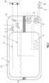
- the storage system comprises a pipe 21 which projects from outside the storage container 1 into the storage container 1, the pipe 21 being closed at its end facing away from the storage container 1 and being open at its end located in the storage container 1, a shut-off valve 22 being arranged on the pipe 21 so that the interior of the pipe 21 is fluidically connected to the interior of the storage container 1 when the shut-off valve 22 is open, and the interior of the pipe 21 is not fluidically connected to the interior of the storage container 1 when the shut-off valve 22 is closed.
- the storage system does not have an internal tank heat exchanger 4 for heating the liquid medium in the storage tank 1.
- the pipe 21 is designed to generate thermoacoustic vibrations so that when connected to a cryogenic medium in the storage tank 1, with the shut-off valve 22 open, a thermoacoustic pressure build-up occurs inside the pipe 21.
- the storage container 1 is double-walled, with an insulating vacuum space between the two walls 1, 11 of the storage container 1, wherein the end of the tube 21 facing away from the storage container 1 lies outside the insulating vacuum space and the end of the tube 21 located in the storage container 1 lies within the insulating vacuum space or the tube passes through the vacuum space and opens into the storage container 1.
- the tube 21 can have a suitable geometry to accommodate a desired tube length in a smaller installation space, for example meander or spiral shape.
- the shut-off valve 22 of the pipe 21 is in Fig. 3 outside the storage container 1 and outside the vacuum space, i.e. outside the outer container 11.
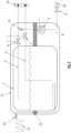
- Fig. 4 In the embodiment of the Fig. 4 is in contrast to Fig. 3 the shut-off valve 22 of the pipe 21 is arranged in the vacuum space, i.e. between the inner container of the storage container 1 and the outer container 11.
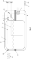
- Fig. 5 shows that the storage system has several such tubes 21 for generating a higher power, which are designed to generate thermoacoustic oscillations and which therefore protrude from outside the storage tank 1 into the storage tank 1.
- a separate shut-off valve 22 is arranged on each pipe 21. This allows, for example, the heat output to be controlled by temporarily activating individual valves.
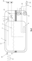
- the design of the Fig. 6 differs from that of the Fig. 5 only because all pipes 21 can be opened and closed together via shut-off valves 22 in a common valve block 24. This simplifies the actuation of the pressure buildup through the multiple pipes 21.
- a heat exchanger 23 is arranged at the end of the tube 21 facing away from the storage tank 1, for transferring heat to the pipe 21, in particular heat from passing air and/or from a cooling liquid.
- a classic pressure build-up system is provided, namely, downstream of the first heat exchanger 3, an inner tank heat exchanger 4 arranged within the storage tank 1 for heating the liquid medium in the storage tank 1, through which the medium taken from the storage tank 1 flows. Due to the heating at the inner tank heat exchanger 4, the liquid medium in the storage tank 1 is partially heated and evaporated.
- the classic pressure build-up system of the Fig. 8 thus corresponds essentially to that of the Fig. 1 and 2 .
- the pressure build-up can be controlled via a partial flow control valve 25.
Landscapes
- Engineering & Computer Science (AREA)
- Physics & Mathematics (AREA)
- Thermal Sciences (AREA)
- Mechanical Engineering (AREA)
- General Engineering & Computer Science (AREA)
- Filling Or Discharging Of Gas Storage Vessels (AREA)
Description
- Die vorliegende Erfindung betrifft ein Speichersystem zur Speicherung eines kryogenen Mediums, insbesondere zur Speicherung von Wasserstoff.
- Es ist bekannt, dass kryogene Medien, also tiefkalte und zumindest teilweise flüssige Medien, wie Wasserstoff oder Helium, in einem Speicherbehälter aufbewahrt werden können, um Energie, beispielsweise zum Antrieb eines Fahrzeugs, eines Schiffes, eines Flugzeugs oder einer Rakete zu transportieren. Das Medium liegt dabei üblicherweise teilweise in flüssiger Form im Speicherbehälter vor und teilweise auch in Gasform.
- Bei kryogenen Speichersystemen ist während des Betriebs ein Druckaufbausystem erforderlich, dass den bei der gasförmigen oder flüssigen Entnahme von beispielsweise Wasserstoff entstehenden Druckabfall ausgleicht. Dies wird in der Regel entweder durch einen Innentankwärmetauscher (geschlossenes Rohrleitungssystem) oder durch direkte Verdampfung (offenes System) gewährleistet. Für diese Art des Druckaufbaues ist einerseits eine Entnahme von Wasserstoff erforderlich andererseits auch eine Wärmequelle (üblicherweise Abwärme des Verbrauchers). Wird kein Wasserstoff entnommen und soll trotzdem ein höheres Druckniveau erreicht werden, so ist dies mit Hilfe von elektrischen Heizern, sogenannten "Blowern" oder mit Kryo-Flüssigkeitspumpen möglich.
- Moderne mobile Flüssigwasserstoffspeicheranwendungen erfordern Druckaufbausysteme, die einerseits einen Druckaufbau ermöglichen ohne Wasserstoff zu entnehmen und andererseits wenig Bauraum einnehmen, wenig Gewicht als auch geringen elektrischen Energiebedarf haben. Elektrische Heizer, Blower und Pumpen können dies nicht oder nur teilweise, mit hohem technischen Aufwand oder hohem elektrischen Energiebedarf, erfüllen, was für mobile Anwendungen einen großen Nachteil darstellt.
- Aus der
DE 196 45 488 C5 ist ein System zum Entnehmen von kaltem Gas aus einem Kryotank bekannt, mit einem isolierten Speicherbehälter für tiefkaltes, verflüssigtes Gas und einer Entnahmeleitung, welche aus dem Speicherbehälter zu einem Verbraucher herausführt, wobei ein Verdampfungsvolumen mit der Entnahmeleitung verbunden ist, wobei flüssiges Gas durch die Entnahmeleitung in das Verdampfungsvolumen gelangt, dort teilweise verdampft und das verdampfte Gas zumindest teilweise über die Entnahmeleitung in den Speicherbehälter zurückströmt, wobei die Entnahmeleitung das einzige Mittel zum Ausgleich eines Druckabfalls beim Entnehmen von kaltem Gas aus dem Kryotank ist. - Es ist eine Aufgabe der Erfindung, ein kryogenes Speichersystem anzugeben, das einen Druckaufbau ohne Entnahme von Wasserstoff auf technisch einfache und kostengünstige Weise ermöglicht.
- Die Lösung der Aufgabe erfolgt durch ein Speichersystem zur Speicherung eines kryogenen Mediums, insbesondere zur Speicherung von Wasserstoff, mit den Merkmalen gemäß Anspruch 1.
- Das Speichersystem umfasst einen Speicherbehälter zur Aufnahme des Mediums, wobei zumindest ein Rohr von außerhalb des Speicherbehälters in den Speicherbehälter ragt, wobei das Rohr an seinem vom Speicherbehälter abgewandten Ende verschlossen ist und an seinem im Speicherbehälter befindlichen Ende offen ist, wobei an dem Rohr an einer bestimmten Position ein Absperrventil angeordnet ist, so dass der Innenraum des Rohres bei geöffnetem Absperrventil mit dem Innenraum des Speicherbehälters fluidleitend verbunden ist und der Innenraum des Rohres bei geschlossenem Absperrventil mit dem Innenraum des Speicherbehälters nicht fluidleitend verbunden ist.
- Erfindungsgemäß ist somit ein Speichersystem, also Tank, zur Speicherung eines kryogenen Mediums, so ausgebildet, dass eine dünne Rohrleitung von außen in den Tank ragt - bevorzugt in die Flüssigkeit im Tank -, wobei die Rohrleitung außen verschlossen ist und die Rohrleitung tankinnenseitig ein offenes Ende aufweist und auf diese Weise das kryogene Medium mit dem Rohrinnenraum in Kontakt treten kann.
- Die Rohrleitung weist ein Absperrventil auf, wobei mittels des Absperrventils der Druck im Tank geregelt/gesteuert werden kann bzw. bei Öffnen des Ventils der Druck im Tank erhöht wird. Das Absperrventil ist bevorzugt durch eine Steuereinrichtung steuerbar, insbesondere öffenbar und schließbar.
- Das Rohr ist dazu eingerichtet, thermoakustische Schwingungen auszubilden, so dass bei Verbindung mit einem kryogenen Medium ein auf thermoakustischen Effekt basierender Druckaufbau im Inneren des Rohres erfolgt.
- Hierdurch kann eine Erhöhung des Drucks im Tank erfolgen, ohne dass, wie sonst üblich, durch Zusatzheizer dem Tank Wärmeenergie zugeführt werden muss.
- Ein thermoakustisches Druckaufbausystem macht sich den Effekt der thermoakustischen Schwingungen (TAO) zunutze, um den Druck im Tanksystem zu erhöhen. Dabei wird das in der Rohrleitung befindliche Gas durch Wärmetransport von der Rohrleitungswand in das Gas in Schwingung versetzt.
- TAO sind für eine lange Speicherdauer von kryogenen Medien, insbesondere Wasserstoff und Helium, unbedingt zu vermeiden, können aber für den vorliegenden Fall des gewünschten Druckaufbaues genutzt werden.
- Die Bauteile beschränken sich dabei erfindungsgemäß auf ein Absperrventil und eine dünne Rohrleitung, die an der warmen Seite bevorzugt eine ausreichend große Wärmeübergangsfläche, zum Beispiel durch Ausbildung von Rohr-Rippen, zur Verfügung stellt. Am warmen Ende, also außerhalb des Speicherbehälters, ist die Rohrleitung geschlossen. Das Rohr ist bevorzugt außerhalb des Speicherbehälters vollständig geschlossen.
- Erfindungsgemäß ist eine Flüssigentnahmeleitung zur Entnahme flüssigen Mediums aus dem Speicherbehälter eingerichtet.
- Vorzugsweise ist das Rohr an seinem vom Speicherbehälter abgewandten Ende, also an der warmen Seite, für verbesserten Wärmeübergang ausgebildet, bevorzugt durch zumindest eine Wärmeübergangsfläche, zum Beispiel durch Rohr-Rippen.
- An dem vom Speicherbehälter abgewandten Ende des Rohres ist gemäß einer nicht beanspruchten Ausführungsform ein Wärmeübertrager angeordnet, zur Übertragung von Wärme an das Rohr, insbesondere von Wärme aus vorbeiströmender Luft und/oder aus einer Kühlflüssigkeit.
- Das kalte offene Ende der Rohrleitung steht dabei bei einem gefüllten Speicherbehälter in die kryogene Flüssigkeit. Die Rohrleitung des vorzugsweise vakuum-isolierten Behälters führt durch den Vakuumraum bis auf die warme Seite, also Außenseite des Behälters. Die Position des Absperrventils der Rohrleitung ist bevorzugt entweder im Vakuumbereich oder knapp an der warmen Seite des Behälters. Die Funktion des Absperrventils ist die gezielte Unterdrückung von thermoakustischen Schwingungen, die im Ruhezustand des Behälters unerwünscht sind. Bei idealer Auslegung des Systems stellt sich thermoakustische Resonanz ein, die einen Druckaufbau innerhalb kürzester Zeit ermöglicht. Wesentlich für die Funktion ist ein entsprechender Temperaturgradient des warmen und des kalten Endes der Rohrleitung. Bevorzugt bildet die Umgebungstemperatur das warme Ende aus und das kalte Ende wird von einer tiefsiedenden Flüssigkeit im Speicherbehälter, wie Wasserstoff oder Helium, gekühlt.
- Bevorzugt ist der Speicherbehälter doppelwandig ausgebildet, mit einem isolierenden Vakuumraum zwischen den beiden Wänden des Speicherbehälters, wobei das vom Speicherbehälter abgewandte Ende des Rohres außerhalb des isolierenden Vakuumraums liegt und das Rohr durch den Vakuumraum hindurchtritt und in den Speicherbehälter mündet. Weiters spielt auch das Verhältnis von Rohrlänge zu Rohrdurchmesser als auch die Wandstärke des Rohres eine wesentliche Rolle. Dabei muss das Rohr möglichst lang und möglichst dünn sein, sowie die Wandstärke möglichst gering.
- Der Innendurchmesser des Rohres ist daher über die gesamte Rohrlänge, oder zumindest außerhalb des Speicherbehälters, also am warmen Ende, gering, bevorzugt maximal 20 mm oder maximal10 mm, besonders bevorzugt maximal6 mm.
- Das Rohr weist außerhalb des Speicherbehälters bevorzugt eine Länge auf von mindestens 50 mm, bevorzugt mindestens 100 mm, besonders bevorzugt mindestens200 mm.
- Das Rohr weist innerhalb des Speicherbehälters bevorzugt eine Länge auf von mindestens 500 mm, bevorzugt mindestens 1000 mm, besonders bevorzugt mindestens 2000 mm.
- Das Rohr weist bevorzugt eine Wandstärke auf von maximal 3 mm, bevorzugt maximal 2 mm, besonders bevorzugt maximal 1 mm.
- Das Verhältnis von gesamter Länge zu Innendurchmesser des Rohres beträgt bevorzugt mindestens100:1, bevorzugt mindestens 400: 1, besonders bevorzugt mindestens 800:1.
- Ein thermoakustisches Druckaufbausystem kann als alleiniges als auch zur Ergänzung von herkömmlichen Druckaufbausystemen eingesetzt werden.
- Um die Leistung des Systems zu erhöhen können mehrere, insbesondere parallel angeordnete, Rohrleitungen verwendet werden.
- Das Speichersystem weist daher bevorzugt mehrere solche Rohre auf, die von außerhalb des Speicherbehälters in den Speicherbehälter ragen, wobei an jedem Rohr ein eigenes Absperrventil angeordnet ist oder zumindest zwei Rohre, bevorzugt alle Rohre, über Absperrventile in einem gemeinsamen Ventilblock geöffnet und geschlossen werden können. Werden mehrere Rohrleitungen parallel verwendet, das heißt die Leistung des Systems durch Parallelanordnung multipliziert, können diese somit über einzelne Ventile oder einen großen "Ventilblock" geschlossen oder geöffnet werden.
- Um die Leistung des Systems weiter zu erhöhen kann auf der warmen Seite der Leitung zusätzlich Wärme über einen Wärmeübertrager eingebracht werden. Diese Wärme kann beispielsweise aus der vorbeiströmenden Luft oder aus der Abwärme des Verbrauchers mittels Kühlflüssigkeit zugeführt werden.
- Um die Leitung(en) im Falle des Ruhezustandes noch besser vor Strahlungswärme von außen zu schützen können diese mit einer Isolation bzw. Strahlungsschilden, beispielsweise Mehrschichtisolation (MLI) umwickelt werden. Je nach Variante ist dann die gesamte oder ein Teil der Leitungslänge im Vakuumraum isoliert. Das Rohr kann somit über einen Rohrabschnitt im Vakuumraum wärmeisoliert ausgebildet sein.
- Für eine weitere Verstärkung des thermoakustischen Effekts kann die Geometrie des Rohrendes im Innentank angepasst werden. zB. eine Reduktion des offenen Querschnitts der Leitung bzw. eine kontinuierliche Verjüngung des Rohrendes. Das Rohr weist daher bevorzugt über einen Rohrabschnitt im Inneren des Speicherbehälters einen geringeren Innendurchmesser auf, als über einen Rohrabschnitt außerhalb des Speicherbehälters, insbesondere einen reduzierten Innendurchmesser oder eine kontinuierliche Verjüngung zu dem im Speicherbehälter befindlichen Ende des Rohres hin.
- Ein thermoakustisches Druckaufbausystem wie zuvor beschrieben, kann auch als Ergänzung zu Druckaufbausystemen nach dem Stand der Technik verwendet werden.
- Die Funktionsweise einer erfindungsgemäßen Vorrichtung ist: Im Ruhezustand ist das in der Leitung befindliche Ventil geschlossen, um thermoakustische Schwingungen zu unterbinden. Ist ein Druckaufbau erwünscht wird das Ventil geöffnet, ein der Umgebungstemperatur ausgesetzter langer Leitungsabschnitt freigegeben und somit das kritische Länge- zu Durchmesser-Verhältnis überschritten. Das im Rohr befindliche Gas beginnt sich aufgrund des Wärmetransportes über die Rohrwand auszudehnen und wieder zusammen zu ziehen, also zu schwingen, stößt mit jeder Schwingung Gas am in die Flüssigkeit stehenden Rohrende aus und saugt Flüssigkeit wieder ein welche im Rohr anschließend zumindest teilweise verdampft. Dadurch wiederholt sich der Effekt bzw. wird dieser weiter verstärkt. Idealerweise stellt sich in kürzester Zeit Resonanz ein, wodurch kontinuierlich Wärme in das System eingebracht wird.
- Die Erfindung wird im Folgenden beispielhaft unter Bezugnahme auf die Zeichnungen beschrieben.
- Fig. 1
- ist eine schematische Darstellung eines nicht erfindungsgemäßen Speichersystem.
- Fig. 2
- ist eine schematische Darstellung eines nicht erfindungsgemäßen Speichersystem in einer alternativen Ausführungsform.
- Fig. 3
- ist eine schematische Darstellung eines erfindungsgemäßen Speichersystem.
- Fig. 4
- ist eine schematische Darstellung eines erfindungsgemäßen Speichersystem in einer alternativen Ausführungsform.
- Fig. 5
- ist eine schematische Darstellung eines erfindungsgemäßen Speichersystem in einer alternativen Ausführungsform.
- Fig. 6
- ist eine schematische Darstellung eines erfindungsgemäßen Speichersystem in einer alternativen Ausführungsform.
- Fig. 7
- ist eine schematische Darstellung eines nicht erfindungsgemäßen Speichersystem in einer alternativen Ausführungsform.
- Fig. 8
- ist eine schematische Darstellung eines erfindungsgemäßen Speichersystem in einer alternativen Ausführungsform.
- In der
Fig.1 ist ein nicht erfindungsgemäßes Speichersystem zur Speicherung eines kryogenen Mediums, insbesondere zur Speicherung von Wasserstoff, dargestellt. - Das Speichersystem umfasst einen Speicherbehälter 1 zur Aufnahme des Mediums. Der Speicherbehälter 1 bildet einen Innenbehälter eines doppelwandigen Behälters, der zusätzlich einen Außenbehälter 11 umfasst. Zwischen Außenbehälter 11 und Innenbehälter, also Speicherbehälter 1, ist ein Vakuum gebildet. Zwischen Außenbehälter 11 und Innenbehälter sind zudem abschnittsweise Aufhängungen 13 angeordnet, um die beiden Schalen des doppelwandigen Behälters zueinander zu positionieren.
- Das kryogene Medium, insbesondere Wasserstoff, befindet sich im unteren Bereich des Speicherbehälters 1, nämlich unterhalb der in den Fig. als Wellenlinie dargestellten Flüssigkeitsoberfläche als Flüssigkeit im Behälter, oberhalb der wellenförmigen Flüssigkeitsoberfläche in gasförmigem Zustand.
- Eine Gasentnahmeleitung 2 ist zur Entnahme des gasförmigen Mediums aus dem Speicherbehälter 1 eingerichtet, so dass das freie Ende der Gasentnahmeleitung 2 oberhalb der Flüssigkeitsoberfläche, in der Nähe der Decke des Speicherbehälters 1, im Speicherbehälter 1 endet.
- Eine Flüssigentnahmeleitung 5 ist zur Entnahme des flüssigen Mediums aus dem Speicherbehälter 1 eingerichtet, so dass das freie Ende der Flüssigentnahmeleitung 5 unterhalb der Flüssigkeitsoberfläche, in der Nähe des Bodens des Speicherbehälters 1, im Speicherbehälter 1 endet.
- Die Begriffe "Decken" und "Boden" beziehen sich dabei auf die übliche Einbaulage des Speicherbehälters, beispielsweise in einer fahrenden, schwimmenden oder fliegenden Transportvorrichtung, wobei die Gravitation in einem Normalbetrieb der Transportvorrichtung in Richtung zum Boden des Speicherbehälters wirkt.
- In der Gasentnahmeleitung 2 ist ein erstes steuerbares Leitungs-Absperrventil 6 angeordnet und in der Flüssigentnahmeleitung 5 ist ein zweites steuerbares Leitungs-Absperrventil 7 angeordnet. Beide Leitungs-Absperrventile befinden sich außerhalb des Speicherbehälters 1. In der
Fig. 1 befinden sich die Leitungs-Absperrventile auch außerhalb des Au-ßenbehälters 11. - In der alternativen Ausführung des Speichersystems die in
Fig. 2 dargestellt ist, sind die beiden Leitungs-Absperrventile innerhalb des Außenbehälters 11 angeordnet, also zwischen dem Innenbehälter, Speicherbehälter 1, und dem Außenbehälter des doppelwandigen Speicherbehälters, insbesondere im Vakuumraum. - Die Leitungs-Absperrventile sind durch eine Steuervorrichtung, die ebenfalls im Vakuumraum (
Fig.2 ) oder außerhalb des gesamten Behälters (Fig. 1 ) angeordnet ist, steuerbar. Dabei kann die Strömung durch die Leitungs-Absperrventile bevorzugt nicht nur unterbrochen werden oder freigegeben werden, sondern auch reduziert werden. - Über die Gasentnahmeleitung 2 und/oder die Flüssigentnahmeleitung 5, bevorzugt auch über das erste Leitungs-Absperrventil 6 und/oder das zweite Leitungs-Absperrventil 7, kann auch eine Betankung des Speicherbehälters 1 aus einer Betankungsvorrichtung 14 erfolgen.
- Die Gasentnahmeleitung 2 und die Flüssigentnahmeleitung 5 werden nach den beiden Leitungs-Absperrventilen 6, 7 zu einer gemeinsamen Leitung zusammengeführt. In der Gasentnahmeleitung 2 kann ein gleichrichtendes Ventil, insbesondere ein Rückschlagventil 15, angeordnet sein, so dass nur die Strömungsrichtung vom ersten Leitungs-Absperrventil 6 zum ersten Wärmetauscher 3 ermöglicht wird, die Gegenrichtung gesperrt wird.
- Die Gasentnahmeleitung 2 und die Flüssigentnahmeleitung 5 sind in Form der gemeinsamen Leitung mit dem außerhalb des Speicherbehälters 1, beispielsweise zwischen Speicherbehälter 1 und Außenbehälter 11 des doppelwandigen Speicherbehälters (
Fig. 2 ), angeordneten ersten Wärmetauscher 3 zur Erwärmung des entnommenen Mediums strömungsverbunden. - Stromabwärts des ersten Wärmetauschers 3 ist innerhalb des Speicherbehälters 1 ein Innentank-Wärmetauscher 4 zur Erwärmung des flüssigen Mediums im Speicherbehälter 1 angeordnet, der vom erwärmten, aus dem Speicherbehälter 1 entnommenen Medium durchflossen wird. Durch die Erwärmung am Innentank-Wärmetauscher 4 wird das flüssige Medium im Speicherbehälter 1 teilweise erwärmt und verdampft.
- In der Gasentnahmeleitung 2 und in der Flüssigentnahmeleitung 5 ist kein steuerbares Dreiwegeventil angeordnet, so dass das gesamte durch die Gasentnahmeleitung 2 und/oder durch die Flüssigentnahmeleitung 5 entnommene und vom ersten Wärmetauscher 3 erwärmte Medium zum Innentank-Wärmetauscher 4 gelangt.
- Da der Druck im Speicherbehälter 1 mittels des ersten und zweiten Leitungs-Absperrventils 6, 7 geregelt wird, ist kein steuerbares Dreiwegeventil erforderlich.
- Eine Steuereinheit des Speichersystems ist dazu eingerichtet, den Druck im Speicherbehälter 1 bei der Entnahme des Mediums dadurch zu steuern, dass die Steuereinheit wahlweise das erste Leitungs-Absperrventil 6 und/oder das zweite Leitungs-Absperrventil 7 öffnet, so dass das Medium wahlweise über die Gasentnahmeleitung 2 und/oder über die Flüssigentnahmeleitung 5 aus dem Speicherbehälter 1 entnommen wird.
- Stromabwärts des Innentank-Wärmetauschers 4 und außerhalb des Speicherbehälters 1, außerhalb (
Fig. 1 ) oder innerhalb (Fig. 2 ) des Außenbehälters 11 des doppelwandigen Behälters, ist ein zweiter Wärmetauscher 8 zur Erwärmung des Mediums angeordnet. - Das über die Gasentnahmeleitung 2 und/oder die Flüssigentnahmeleitung 5 entnommene Medium wird stromabwärts des Innentank-Wärmetauschers 4 einem Verbraucher 10 zugeführt, insbesondere einer Brennstoffzelle. Zwischen dem zweiten Wärmetauscher 8 und dem Verbraucher 10 ist ein drittes Leitungs-Absperrventil 9 angeordnet.
- Die Ausführungsform der
Fig. 2 unterscheidet sich dadurch von derFig. 1 , dass steuerungsrelevante Komponenten des Speichersystems, wie der erste Wärmetauscher 3, der zweite Wärmetauscher 8, das erste Leitungs-Absperrventil 6 und das zweite Leitungs-Absperrventil 8, sowie das Rückschlagventil 15 innerhalb des Außenbehälters 11 angeordnet sind, nicht außerhalb des Außenbehälters 11 wie inFig. 1 , und somit im Zwischenraum des doppelwandigen Behälters angeordnet sind, der einen Vakuumraum bildet. - In der
Fig. 3 ist ein erfindungsgemäßes Speichersystem zur Speicherung eines kryogenen Mediums, insbesondere zur Speicherung von Wasserstoff, dargestellt. - Das erfindungsgemäße Speichersystem umfasst ein Rohr 21, dass von außerhalb des Speicherbehälters 1 in den Speicherbehälter 1 ragt, wobei das Rohr 21 an seinem vom Speicherbehälter 1 abgewandten Ende verschlossen ist und an seinem im Speicherbehälter 1 befindlichen Ende offen ist, wobei an dem Rohr 21 ein Absperrventil 22 angeordnet ist, so dass der Innenraum des Rohres 21 bei geöffnetem Absperrventil 22 mit dem Innenraum des Speicherbehälters 1 fluidleitend verbunden ist und der Innenraum des Rohres 21 bei geschlossenem Absperrventil 22 mit dem Innenraum des Speicherbehälters 1 nicht fluidleitend verbunden ist.
- Das Speichersystem weist keinen Innentank-Wärmetauscher 4 zur Erwärmung des flüssigen Mediums im Speicherbehälter 1 auf.
- Das Rohr 21 ist dazu eingerichtet, thermoakustische Schwingungen auszubilden, so dass bei Verbindung mit einem kryogenen Medium im Speicherbehälter 1, bei geöffnetem Absperrventil 22, ein thermoakustischer Druckaufbau im Inneren des Rohres 21 erfolgt.
- Der Speicherbehälter 1 ist doppelwandig ausgebildet, mit einem isolierenden Vakuumraum zwischen den beiden Wänden 1, 11 des Speicherbehälters 1, wobei das vom Speicherbehälter 1 abgewandte Ende des Rohres 21 außerhalb des isolierenden Vakuumraums liegt und das im Speicherbehälter 1 befindliche Ende des Rohres 21 innerhalb des isolierenden Vakuumraums liegt bzw. das Rohr durch den Vakuumraum hindurchtritt und in den Speicherbehälter 1 mündet.
- Das Rohr 21 kann eine geeignete Geometrie aufweisen, um eine gewünschte Rohrlänge auf kleinerem Bauraum unterzubringen, beispielsweise Mäander- oder Spiralform.
- Das Absperrventil 22 des Rohres 21 ist in
Fig. 3 außerhalb des Speicherbehälters 1 und außerhalb des Vakuumraums, also außerhalb des Außenbehälters 11 angeordnet. - In der Ausführungsform der
Fig. 4 ist im Gegensatz zuFig. 3 das Absperrventil 22 des Rohres 21 im Vakuumraum angeordnet, also zwischen dem Innenbehälter des Speicherbehälters 1 und dem Außenbehälter 11. -
Fig. 5 zeigt, dass das Speichersystem zur Ausbildung einer höheren Leistung mehrere solche Rohre 21 aufweist, die zur Ausbildung von thermoakustischen Schwingungen eingerichtet sind und die daher von außerhalb des Speicherbehälters 1 in den Speicherbehälter 1 ragen. InFig. 5 ist an jedem Rohr 21 ein eigenes Absperrventil 22 angeordnet. Damit kann beispielsweise die Wärmeleistung durch zeitweise Aktivierung einzelner Ventile gesteuert werden. - Die Ausführungsform der
Fig. 6 unterscheidet sich von jener derFig. 5 nur dadurch, dass alle Rohre 21 über Absperrventile 22 in einem gemeinsamen Ventilblock 24 gemeinsam geöffnet und geschlossen werden können. Die Aktuierung des Druckaufbaus durch die mehreren Rohre 21 wird dadurch vereinfacht. - In der nicht erfindungsgemäßen Ausführungsform der
Fig. 7 ist, an dem vom Speicherbehälter 1 abgewandten Ende des Rohres 21 ein Wärmeübertrager 23 angeordnet, zur Übertragung von Wärme an das Rohr 21, insbesondere von Wärme aus vorbeiströmender Luft und/oder aus einer Kühlflüssigkeit. - Die erfindungsgemäße Ausführungsform der
Fig. 8 schließlich weist zusätzlich zu dem thermoakustisches Druckaufbausystem mittels Rohr 21 ein klassisches Druckaufbausystem auf, nämlich stromabwärts des ersten Wärmetauschers 3 einen innerhalb des Speicherbehälters 1 angeordneten Innentank-Wärmetauscher 4 zur Erwärmung des flüssigen Mediums im Speicherbehälter 1, der von dem, aus dem Speicherbehälter 1 entnommenen Medium durchflossen wird. Durch die Erwärmung am Innentank-Wärmetauscher 4 wird das flüssige Medium im Speicherbehälter 1 teilweise erwärmt und verdampft. Das klassische Druckaufbausystem derFig. 8 entspricht somit im Wesentlichen demjenigen derFig. 1 und2 . Hierbei kann der Druckaufbau über ein Teilstromregelventil 25 geregelt werden. - Es wird darauf hingewiesen, dass die Figuren rein schematisch dargestellt sind und nicht die tatsächlichen Größen- und Längenverhältnisse wiedergeben müssen.
-
- 1
- Speicherbehälter
- 2
- Gasentnahmeleitung
- 3
- erster Wärmetauscher
- 4
- Innentank-Wärmetauscher
- 5
- Flüssigentnahmeleitung
- 6
- erstes steuerbares Leitungs-Absperrventil
- 7
- zweites steuerbares Leitungs-Absperrventil
- 8
- zweiter Wärmetauscher
- 9
- drittes steuerbares Leitungs-Absperrventil
- 10
- Verbraucher
- 11
- Außenbehälter
- 13
- Aufhängung
- 14
- Betankungsvorrichtung
- 15
- Rückschlagventil
- 21
- Rohr
- 22
- Absperrventil
- 23
- Wärmeübertrager
- 24
- Ventilblock
- 25
- Teilstromregelventil
Claims (8)
- Speichersystem zur Speicherung eines kryogenen Mediums, insbesondere zur Speicherung von Wasserstoff, umfassend einen Speicherbehälter (1) zur Aufnahme des Mediums,
wobei zumindest ein Rohr (21) von außerhalb des Speicherbehälters (1) in den Speicherbehälter (1) ragt, wobei das Rohr (21) an seinem vom Speicherbehälter (1) abgewandten Ende verschlossen ist und an seinem im Speicherbehälter (1) befindlichen Ende offen ist, wobei an dem Rohr (21) ein Absperrventil (22) angeordnet ist, so dass der Innenraum des Rohres (21) bei geöffnetem Absperrventil (22) mit dem Innenraum des Speicherbehälters (1) fluidleitend verbunden ist und der Innenraum des Rohres (21) bei geschlossenem Absperrventil (22) mit dem Innenraum des Speicherbehälters (1) nicht fluidleitend verbunden ist, wobei der Außendurchmesser des Rohrs (21) über die gesamte Rohrlänge gering ist, wobei das Rohr (21) dazu eingerichtet ist, thermoakustische Schwingungen auszubilden und somit Teil eines thermoakustischen Druckaufbausystems ist, wobei sich die Bauteile des thermoakustischen Druckaufbausystems auf eine dünne Rohrleitung des Rohrs (21) und das Absperrventil (22) beschränken, wobei eine Flüssigentnahmeleitung (5) zur Entnahme flüssigen Mediums aus dem Speicherbehälter (1) eingerichtet ist. - Speichersystem nach Anspruch 1,
dadurch gekennzeichnet , dass der Speicherbehälter (1) doppelwandig ausgebildet ist, mit einem isolierenden Vakuumraum zwischen den beiden Wänden des Speicherbehälters (1), wobei das vom Speicherbehälter (1) abgewandte Ende des Rohres (21) außerhalb des isolierenden Vakuumraums liegt und das Rohr (21) durch den Vakuumraum hindurchtritt und in den Speicherbehälter (1) mündet. - Speichersystem nach zumindest einem der vorhergehenden Ansprüche,
dadurch gekennzeichnet , dass das Rohr (21) an seinem vom Speicherbehälter (1) abgewandten Ende für verbesserten Wärmeübergang ausgebildet ist, bevorzugt durch zumindest eine Wärmeübergangsfläche, zum Beispiel durch Rohr-Rippen. - Speichersystem nach zumindest einem der vorhergehenden Ansprüche,
dadurch gekennzeichnet , dass der Innendurchmesser des Rohres (21) über die gesamte Rohrlänge maximal 20 mm, bevorzugt maximal 10 mm, besonders bevorzugt maximal 6 mm ist. - Speichersystem nach zumindest einem der vorhergehenden Ansprüche,
dadurch gekennzeichnet , dass das Rohr (21) außerhalb des Speicherbehälters (1) eine Länge aufweist, von mindestens 50mm, bevorzugt mindestens 100 mm, besonders bevorzugt mindestens 200 mm und/oder dass das Verhältnis von gesamter Länge zu Innendurchmesser des Rohres (21) mindestens 100:1 beträgt, bevorzugt mindestens 400:1, besonders bevorzugt mindestens 800:1. - Speichersystem nach zumindest einem der vorhergehenden Ansprüche,
dadurch gekennzeichnet , dass das Speichersystem mehrere solche Rohre (21) aufweist, die von außerhalb des Speicherbehälters (1) in den Speicherbehälter (1) ragen, wobei an jedem Rohr (21) ein eigenes Absperrventil (22) angeordnet ist oder wobei zumindest zwei Rohre (21), bevorzugt alle Rohre (21), über Absperrventile (22) in einem gemeinsamen Ventilblock (24) geöffnet und geschlossen werden können. - Speichersystem nach zumindest einem der vorhergehenden Ansprüche,
dadurch gekennzeichnet , dass das Rohr (21) über einen Rohrabschnitt im Vakuumraum wärmeisoliert ausgebildet ist. - Speichersystem nach zumindest einem der vorhergehenden Ansprüche,
dadurch gekennzeichnet , dass das Rohr (21) über einen Rohrabschnitt im Inneren des Speicherbehälters einen geringeren Innendurchmesser aufweist, als über einen Rohrabschnitt außerhalb des Speicherbehälters, insbesondere einen reduzierten Innendurchmesser oder eine kontinuierliche Verjüngung zu dem im Speicherbehälter befindlichen Ende des Rohres hin.
Applications Claiming Priority (1)
| Application Number | Priority Date | Filing Date | Title |
|---|---|---|---|
| DE102021210616.1A DE102021210616B3 (de) | 2021-09-23 | 2021-09-23 | Kryogen-Speichersystem |
Publications (2)
| Publication Number | Publication Date |
|---|---|
| EP4155601A1 EP4155601A1 (de) | 2023-03-29 |
| EP4155601B1 true EP4155601B1 (de) | 2025-06-18 |
Family
ID=83228708
Family Applications (1)
| Application Number | Title | Priority Date | Filing Date |
|---|---|---|---|
| EP22194030.7A Active EP4155601B1 (de) | 2021-09-23 | 2022-09-06 | Kryogen-speichersystem |
Country Status (4)
| Country | Link |
|---|---|
| US (1) | US12366328B2 (de) |
| EP (1) | EP4155601B1 (de) |
| CN (1) | CN115854251A (de) |
| DE (1) | DE102021210616B3 (de) |
Families Citing this family (2)
| Publication number | Priority date | Publication date | Assignee | Title |
|---|---|---|---|---|
| EP4279795B1 (de) * | 2022-05-17 | 2026-04-22 | Zero Emissions Aerospace Limited | Brennstoffzuführsystem |
| EP4350200B1 (de) * | 2022-10-04 | 2025-12-03 | MAGNA STEYR Fahrzeugtechnik GmbH & Co KG | Kryotankvorrichtung mit wärmetauscher |
Family Cites Families (11)
| Publication number | Priority date | Publication date | Assignee | Title |
|---|---|---|---|---|
| JP3037073B2 (ja) * | 1994-07-20 | 2000-04-24 | 株式会社神戸製鋼所 | 低温液体の気化装置 |
| DE19645488C5 (de) * | 1996-11-05 | 2012-08-30 | Air Liquide Deutschland Gmbh | System und Verfahren zum Entnehmen von kaltem Gas aus einem Kryotank |
| DE19853531C2 (de) * | 1998-11-20 | 2001-01-25 | Messer Griesheim Gmbh | Vorrichtung zur Entnahme eines unter Druck stehenden flüssigen Gasstromes aus einem Druckbehälter |
| DE10040679A1 (de) * | 2000-08-19 | 2002-02-28 | Messer Griesheim Gmbh | Vorrichtung und Verfahren zur druckgeregelten Versorgung aus einem Flüssiggastank |
| DE102004011653A1 (de) | 2004-03-10 | 2005-09-29 | Bayerische Motoren Werke Ag | Druckbehälter für kondensierte Gase mit Kühlschild |
| CA2506606C (en) * | 2005-06-03 | 2006-09-12 | Westport Research Inc. | Storage tank for a cryogenic liquid and method of re-filling same |
| US20100236284A1 (en) * | 2009-03-23 | 2010-09-23 | Denyse Claire Dubrucq Living Trust | Preserving liquids in cryogenic processes |
| CN107614962B (zh) * | 2015-04-30 | 2020-09-11 | 西港能源有限公司 | 用于低温流体系统的智能压力管理系统 |
| WO2019083537A1 (en) * | 2017-10-26 | 2019-05-02 | 21St Century Medicine, Inc. | CRYOGENIC STORAGE SYSTEM HAVING ENHANCED THERMAL STABILITY |
| FR3094070B1 (fr) * | 2019-03-21 | 2021-10-15 | Air Liquide | Dispositif et procédé de stockage et de fourniture de carburant fluide. |
| DE102020206689B3 (de) * | 2020-05-28 | 2021-08-19 | Magna Steyr Fahrzeugtechnik Ag & Co Kg | Kryogen-Speichersystem |
-
2021
- 2021-09-23 DE DE102021210616.1A patent/DE102021210616B3/de active Active
-
2022
- 2022-09-06 EP EP22194030.7A patent/EP4155601B1/de active Active
- 2022-09-23 CN CN202211164157.9A patent/CN115854251A/zh active Pending
- 2022-09-26 US US17/935,290 patent/US12366328B2/en active Active
Also Published As
| Publication number | Publication date |
|---|---|
| US20230089359A1 (en) | 2023-03-23 |
| DE102021210616B3 (de) | 2023-01-05 |
| CN115854251A (zh) | 2023-03-28 |
| US12366328B2 (en) | 2025-07-22 |
| EP4155601A1 (de) | 2023-03-29 |
Similar Documents
| Publication | Publication Date | Title |
|---|---|---|
| DE102020206689B3 (de) | Kryogen-Speichersystem | |
| EP4155601B1 (de) | Kryogen-speichersystem | |
| EP1287285B1 (de) | Speicherbehälter für kryogenen treibstoff | |
| EP1779025B1 (de) | Speicherbehälter für kryogene medien | |
| DE102006025656B4 (de) | Vorrichtung zur Kraftstoffspeicherung und -förderung von kryogenem Kraftstoff | |
| EP1412954A2 (de) | Einrichtung zur rekondensation von tiefsiedenden gasen mit einem kryogenerator des aus einem flussiggas-behalter verdampfenden gases | |
| EP1736723A2 (de) | Kryostatanordnung mit Kryokühler | |
| DE102017205279B3 (de) | Kryostatanordnung mit einem Halsrohr mit einer tragenden Struktur und ein die tragende Struktur umgebendes Außenrohr zur Verringerung des Kryogenverbrauchs | |
| EP1924804B1 (de) | Treibstofftank für kryogene flüssigkeiten | |
| WO2010127671A2 (de) | Verfahren zur speicherung von und speicher für technische gase | |
| EP3210890B1 (de) | Kühlung von treibstoff für ein triebwerk | |
| EP4279794B1 (de) | Kryotank | |
| EP1742234B1 (de) | Unterkühlte Horizontalkryostatanordnung | |
| AT10015U1 (de) | Speicherbehälter für tiefkaltes flüssiggas mit einer entnahmevorrichtung | |
| DE102021213644B4 (de) | Kryogen-Speichersystem | |
| DE102007052259A1 (de) | Kraftstoffversorgungseinrichtung für ein mit Wasserstoff zu betreibendes Kraftfahrzeug | |
| EP4279797A1 (de) | Kryotank | |
| EP4400761B1 (de) | Kryotank umfassend eine entnahmevorrichtung | |
| DE102016014927A1 (de) | Kraftstoffsystem mit einem Tank zum Speichern von Flüssiggas als Kraftstoff | |
| EP4267388A1 (de) | Tanksystem zur lagerung kühler medien | |
| DE202009008405U1 (de) | Wärmepumpsystem | |
| DE102022207627B4 (de) | Kryotankvorrichtung | |
| DE102024114886A1 (de) | Tanksystem und Verfahren zur Versorgung eines Verbrauchers | |
| DE19853531C2 (de) | Vorrichtung zur Entnahme eines unter Druck stehenden flüssigen Gasstromes aus einem Druckbehälter | |
| DE102017217347A1 (de) | Druckbehältersystem und Verfahren zum Zuführen von Brennstoff aus einem Druckbehältersystem |
Legal Events
| Date | Code | Title | Description |
|---|---|---|---|
| PUAI | Public reference made under article 153(3) epc to a published international application that has entered the european phase |
Free format text: ORIGINAL CODE: 0009012 |
|
| STAA | Information on the status of an ep patent application or granted ep patent |
Free format text: STATUS: THE APPLICATION HAS BEEN PUBLISHED |
|
| AK | Designated contracting states |
Kind code of ref document: A1 Designated state(s): AL AT BE BG CH CY CZ DE DK EE ES FI FR GB GR HR HU IE IS IT LI LT LU LV MC MK MT NL NO PL PT RO RS SE SI SK SM TR |
|
| STAA | Information on the status of an ep patent application or granted ep patent |
Free format text: STATUS: REQUEST FOR EXAMINATION WAS MADE |
|
| 17P | Request for examination filed |
Effective date: 20230921 |
|
| RBV | Designated contracting states (corrected) |
Designated state(s): AL AT BE BG CH CY CZ DE DK EE ES FI FR GB GR HR HU IE IS IT LI LT LU LV MC MK MT NL NO PL PT RO RS SE SI SK SM TR |
|
| GRAP | Despatch of communication of intention to grant a patent |
Free format text: ORIGINAL CODE: EPIDOSNIGR1 |
|
| STAA | Information on the status of an ep patent application or granted ep patent |
Free format text: STATUS: GRANT OF PATENT IS INTENDED |
|
| INTG | Intention to grant announced |
Effective date: 20250305 |
|
| GRAS | Grant fee paid |
Free format text: ORIGINAL CODE: EPIDOSNIGR3 |
|
| GRAA | (expected) grant |
Free format text: ORIGINAL CODE: 0009210 |
|
| STAA | Information on the status of an ep patent application or granted ep patent |
Free format text: STATUS: THE PATENT HAS BEEN GRANTED |
|
| AK | Designated contracting states |
Kind code of ref document: B1 Designated state(s): AL AT BE BG CH CY CZ DE DK EE ES FI FR GB GR HR HU IE IS IT LI LT LU LV MC MK MT NL NO PL PT RO RS SE SI SK SM TR |
|
| REG | Reference to a national code |
Ref country code: GB Ref legal event code: FG4D Free format text: NOT ENGLISH |
|
| REG | Reference to a national code |
Ref country code: CH Ref legal event code: EP |
|
| REG | Reference to a national code |
Ref country code: DE Ref legal event code: R096 Ref document number: 502022004305 Country of ref document: DE |
|
| REG | Reference to a national code |
Ref country code: CH Ref legal event code: EP |
|
| REG | Reference to a national code |
Ref country code: IE Ref legal event code: FG4D Free format text: LANGUAGE OF EP DOCUMENT: GERMAN |
|
| PG25 | Lapsed in a contracting state [announced via postgrant information from national office to epo] |
Ref country code: FI Free format text: LAPSE BECAUSE OF FAILURE TO SUBMIT A TRANSLATION OF THE DESCRIPTION OR TO PAY THE FEE WITHIN THE PRESCRIBED TIME-LIMIT Effective date: 20250618 |
|
| PGFP | Annual fee paid to national office [announced via postgrant information from national office to epo] |
Ref country code: DE Payment date: 20250919 Year of fee payment: 4 |
|
| REG | Reference to a national code |
Ref country code: LT Ref legal event code: MG9D |
|
| PG25 | Lapsed in a contracting state [announced via postgrant information from national office to epo] |
Ref country code: GR Free format text: LAPSE BECAUSE OF FAILURE TO SUBMIT A TRANSLATION OF THE DESCRIPTION OR TO PAY THE FEE WITHIN THE PRESCRIBED TIME-LIMIT Effective date: 20250919 Ref country code: NO Free format text: LAPSE BECAUSE OF FAILURE TO SUBMIT A TRANSLATION OF THE DESCRIPTION OR TO PAY THE FEE WITHIN THE PRESCRIBED TIME-LIMIT Effective date: 20250918 |
|
| PG25 | Lapsed in a contracting state [announced via postgrant information from national office to epo] |
Ref country code: BG Free format text: LAPSE BECAUSE OF FAILURE TO SUBMIT A TRANSLATION OF THE DESCRIPTION OR TO PAY THE FEE WITHIN THE PRESCRIBED TIME-LIMIT Effective date: 20250618 |
|
| PG25 | Lapsed in a contracting state [announced via postgrant information from national office to epo] |
Ref country code: HR Free format text: LAPSE BECAUSE OF FAILURE TO SUBMIT A TRANSLATION OF THE DESCRIPTION OR TO PAY THE FEE WITHIN THE PRESCRIBED TIME-LIMIT Effective date: 20250618 |
|
| PGFP | Annual fee paid to national office [announced via postgrant information from national office to epo] |
Ref country code: FR Payment date: 20250922 Year of fee payment: 4 Ref country code: AT Payment date: 20251020 Year of fee payment: 4 |
|
| PG25 | Lapsed in a contracting state [announced via postgrant information from national office to epo] |
Ref country code: RS Free format text: LAPSE BECAUSE OF FAILURE TO SUBMIT A TRANSLATION OF THE DESCRIPTION OR TO PAY THE FEE WITHIN THE PRESCRIBED TIME-LIMIT Effective date: 20250918 |
|
| REG | Reference to a national code |
Ref country code: NL Ref legal event code: MP Effective date: 20250618 |
|
| PG25 | Lapsed in a contracting state [announced via postgrant information from national office to epo] |
Ref country code: LV Free format text: LAPSE BECAUSE OF FAILURE TO SUBMIT A TRANSLATION OF THE DESCRIPTION OR TO PAY THE FEE WITHIN THE PRESCRIBED TIME-LIMIT Effective date: 20250618 |
|
| PG25 | Lapsed in a contracting state [announced via postgrant information from national office to epo] |
Ref country code: NL Free format text: LAPSE BECAUSE OF FAILURE TO SUBMIT A TRANSLATION OF THE DESCRIPTION OR TO PAY THE FEE WITHIN THE PRESCRIBED TIME-LIMIT Effective date: 20250618 |
|
| PG25 | Lapsed in a contracting state [announced via postgrant information from national office to epo] |
Ref country code: PT Free format text: LAPSE BECAUSE OF FAILURE TO SUBMIT A TRANSLATION OF THE DESCRIPTION OR TO PAY THE FEE WITHIN THE PRESCRIBED TIME-LIMIT Effective date: 20251020 |
|
| PG25 | Lapsed in a contracting state [announced via postgrant information from national office to epo] |
Ref country code: IS Free format text: LAPSE BECAUSE OF FAILURE TO SUBMIT A TRANSLATION OF THE DESCRIPTION OR TO PAY THE FEE WITHIN THE PRESCRIBED TIME-LIMIT Effective date: 20251018 |
|
| PG25 | Lapsed in a contracting state [announced via postgrant information from national office to epo] |
Ref country code: SM Free format text: LAPSE BECAUSE OF FAILURE TO SUBMIT A TRANSLATION OF THE DESCRIPTION OR TO PAY THE FEE WITHIN THE PRESCRIBED TIME-LIMIT Effective date: 20250618 |
|
| PG25 | Lapsed in a contracting state [announced via postgrant information from national office to epo] |
Ref country code: CZ Free format text: LAPSE BECAUSE OF FAILURE TO SUBMIT A TRANSLATION OF THE DESCRIPTION OR TO PAY THE FEE WITHIN THE PRESCRIBED TIME-LIMIT Effective date: 20250618 |
|
| PG25 | Lapsed in a contracting state [announced via postgrant information from national office to epo] |
Ref country code: PL Free format text: LAPSE BECAUSE OF FAILURE TO SUBMIT A TRANSLATION OF THE DESCRIPTION OR TO PAY THE FEE WITHIN THE PRESCRIBED TIME-LIMIT Effective date: 20250618 |
|
| PG25 | Lapsed in a contracting state [announced via postgrant information from national office to epo] |
Ref country code: EE Free format text: LAPSE BECAUSE OF FAILURE TO SUBMIT A TRANSLATION OF THE DESCRIPTION OR TO PAY THE FEE WITHIN THE PRESCRIBED TIME-LIMIT Effective date: 20250618 |
|
| PG25 | Lapsed in a contracting state [announced via postgrant information from national office to epo] |
Ref country code: SK Free format text: LAPSE BECAUSE OF FAILURE TO SUBMIT A TRANSLATION OF THE DESCRIPTION OR TO PAY THE FEE WITHIN THE PRESCRIBED TIME-LIMIT Effective date: 20250618 |
|
| PG25 | Lapsed in a contracting state [announced via postgrant information from national office to epo] |
Ref country code: ES Free format text: LAPSE BECAUSE OF FAILURE TO SUBMIT A TRANSLATION OF THE DESCRIPTION OR TO PAY THE FEE WITHIN THE PRESCRIBED TIME-LIMIT Effective date: 20250618 |
|
| PG25 | Lapsed in a contracting state [announced via postgrant information from national office to epo] |
Ref country code: RO Free format text: LAPSE BECAUSE OF FAILURE TO SUBMIT A TRANSLATION OF THE DESCRIPTION OR TO PAY THE FEE WITHIN THE PRESCRIBED TIME-LIMIT Effective date: 20250618 |
|
| PG25 | Lapsed in a contracting state [announced via postgrant information from national office to epo] |
Ref country code: DK Free format text: LAPSE BECAUSE OF FAILURE TO SUBMIT A TRANSLATION OF THE DESCRIPTION OR TO PAY THE FEE WITHIN THE PRESCRIBED TIME-LIMIT Effective date: 20250618 |
|
| PG25 | Lapsed in a contracting state [announced via postgrant information from national office to epo] |
Ref country code: IT Free format text: LAPSE BECAUSE OF FAILURE TO SUBMIT A TRANSLATION OF THE DESCRIPTION OR TO PAY THE FEE WITHIN THE PRESCRIBED TIME-LIMIT Effective date: 20250618 |
|
| PLBE | No opposition filed within time limit |
Free format text: ORIGINAL CODE: 0009261 |
|
| STAA | Information on the status of an ep patent application or granted ep patent |
Free format text: STATUS: NO OPPOSITION FILED WITHIN TIME LIMIT |
|
| REG | Reference to a national code |
Ref country code: CH Ref legal event code: H13 Free format text: ST27 STATUS EVENT CODE: U-0-0-H10-H13 (AS PROVIDED BY THE NATIONAL OFFICE) Effective date: 20260425 |
|
| REG | Reference to a national code |
Ref country code: CH Ref legal event code: L10 Free format text: ST27 STATUS EVENT CODE: U-0-0-L10-L00 (AS PROVIDED BY THE NATIONAL OFFICE) Effective date: 20260430 |