EP4155596B1 - Verbindungsanordnung und kühlanordnung - Google Patents
Verbindungsanordnung und kühlanordnung Download PDFInfo
- Publication number
- EP4155596B1 EP4155596B1 EP22197330.8A EP22197330A EP4155596B1 EP 4155596 B1 EP4155596 B1 EP 4155596B1 EP 22197330 A EP22197330 A EP 22197330A EP 4155596 B1 EP4155596 B1 EP 4155596B1
- Authority
- EP
- European Patent Office
- Prior art keywords
- flange
- connection assembly
- internal
- orifice
- male body
- Prior art date
- Legal status (The legal status is an assumption and is not a legal conclusion. Google has not performed a legal analysis and makes no representation as to the accuracy of the status listed.)
- Active
Links
Images


Classifications
-
- F—MECHANICAL ENGINEERING; LIGHTING; HEATING; WEAPONS; BLASTING
- F16—ENGINEERING ELEMENTS AND UNITS; GENERAL MEASURES FOR PRODUCING AND MAINTAINING EFFECTIVE FUNCTIONING OF MACHINES OR INSTALLATIONS; THERMAL INSULATION IN GENERAL
- F16L—PIPES; JOINTS OR FITTINGS FOR PIPES; SUPPORTS FOR PIPES, CABLES OR PROTECTIVE TUBING; MEANS FOR THERMAL INSULATION IN GENERAL
- F16L37/00—Couplings of the quick-acting type
- F16L37/50—Couplings of the quick-acting type adjustable; allowing movement of the parts joined
- F16L37/52—Universal joints, i.e. with a mechanical connection allowing angular movement or adjustment of the axes of the parts in any direction
-
- F—MECHANICAL ENGINEERING; LIGHTING; HEATING; WEAPONS; BLASTING
- F16—ENGINEERING ELEMENTS AND UNITS; GENERAL MEASURES FOR PRODUCING AND MAINTAINING EFFECTIVE FUNCTIONING OF MACHINES OR INSTALLATIONS; THERMAL INSULATION IN GENERAL
- F16L—PIPES; JOINTS OR FITTINGS FOR PIPES; SUPPORTS FOR PIPES, CABLES OR PROTECTIVE TUBING; MEANS FOR THERMAL INSULATION IN GENERAL
- F16L29/00—Joints with fluid cut-off means
- F16L29/04—Joints with fluid cut-off means with a cut-off device in each of the two pipe ends, the cut-off devices being automatically opened when the coupling is applied
-
- F—MECHANICAL ENGINEERING; LIGHTING; HEATING; WEAPONS; BLASTING
- F16—ENGINEERING ELEMENTS AND UNITS; GENERAL MEASURES FOR PRODUCING AND MAINTAINING EFFECTIVE FUNCTIONING OF MACHINES OR INSTALLATIONS; THERMAL INSULATION IN GENERAL
- F16L—PIPES; JOINTS OR FITTINGS FOR PIPES; SUPPORTS FOR PIPES, CABLES OR PROTECTIVE TUBING; MEANS FOR THERMAL INSULATION IN GENERAL
- F16L37/00—Couplings of the quick-acting type
- F16L37/56—Couplings of the quick-acting type for double-walled or multi-channel pipes or pipe assemblies
-
- F—MECHANICAL ENGINEERING; LIGHTING; HEATING; WEAPONS; BLASTING
- F16—ENGINEERING ELEMENTS AND UNITS; GENERAL MEASURES FOR PRODUCING AND MAINTAINING EFFECTIVE FUNCTIONING OF MACHINES OR INSTALLATIONS; THERMAL INSULATION IN GENERAL
- F16L—PIPES; JOINTS OR FITTINGS FOR PIPES; SUPPORTS FOR PIPES, CABLES OR PROTECTIVE TUBING; MEANS FOR THERMAL INSULATION IN GENERAL
- F16L39/00—Joints or fittings for double-walled or multi-channel pipes or pipe assemblies
-
- F—MECHANICAL ENGINEERING; LIGHTING; HEATING; WEAPONS; BLASTING
- F16—ENGINEERING ELEMENTS AND UNITS; GENERAL MEASURES FOR PRODUCING AND MAINTAINING EFFECTIVE FUNCTIONING OF MACHINES OR INSTALLATIONS; THERMAL INSULATION IN GENERAL
- F16L—PIPES; JOINTS OR FITTINGS FOR PIPES; SUPPORTS FOR PIPES, CABLES OR PROTECTIVE TUBING; MEANS FOR THERMAL INSULATION IN GENERAL
- F16L41/00—Branching pipes; Joining pipes to walls
- F16L41/08—Joining pipes to walls or pipes, the joined pipe axis being perpendicular to the plane of a wall or to the axis of another pipe
- F16L41/12—Joining pipes to walls or pipes, the joined pipe axis being perpendicular to the plane of a wall or to the axis of another pipe using attaching means embracing the pipe
-
- F—MECHANICAL ENGINEERING; LIGHTING; HEATING; WEAPONS; BLASTING
- F16—ENGINEERING ELEMENTS AND UNITS; GENERAL MEASURES FOR PRODUCING AND MAINTAINING EFFECTIVE FUNCTIONING OF MACHINES OR INSTALLATIONS; THERMAL INSULATION IN GENERAL
- F16L—PIPES; JOINTS OR FITTINGS FOR PIPES; SUPPORTS FOR PIPES, CABLES OR PROTECTIVE TUBING; MEANS FOR THERMAL INSULATION IN GENERAL
- F16L29/00—Joints with fluid cut-off means
- F16L29/02—Joints with fluid cut-off means with a cut-off device in one of the two pipe ends, the cut-off device being automatically opened when the coupling is applied
-
- F—MECHANICAL ENGINEERING; LIGHTING; HEATING; WEAPONS; BLASTING
- F28—HEAT EXCHANGE IN GENERAL
- F28F—DETAILS OF HEAT-EXCHANGE AND HEAT-TRANSFER APPARATUS, OF GENERAL APPLICATION
- F28F9/00—Casings; Header boxes; Auxiliary supports for elements; Auxiliary members within casings
- F28F9/02—Header boxes; End plates
- F28F9/0246—Arrangements for connecting header boxes with flow lines
- F28F9/0251—Massive connectors, e.g. blocks; Plate-like connectors
- F28F9/0253—Massive connectors, e.g. blocks; Plate-like connectors with multiple channels, e.g. with combined inflow and outflow channels
Definitions
- the present invention relates to a connection assembly, and a thermoregulation assembly comprising such a connection assembly.
- thermoregulation circuits designed to regulate the temperature of a heat exchange plate for example in the field of cooling circuits designed to cool a heat exchange plate called a "cold plate”
- a connection assembly so as to establish a fluid connection between them to circulate a thermoregulation fluid.
- the connection assembly comprises at least two fluidic connection elements, for example male elements
- the cold plate comprises at least two complementary fluidic connection elements, for example female elements, each complementary connection element being arranged to be coupled to a respective fluidic connection element.
- connection assembly and the complementary elements of the heat exchange plate are generally not perfectly aligned, which increases the risk of jamming and /or wear when connecting a connection assembly and the associated plate.
- connection assembly which makes it possible to compensate for alignment and spacing faults while remaining compact.
- connection assembly comprises, for each fluidic connection element, both a first compensation device allowing lateral movement, in all directions carried by the transverse plane, and a second compensation device. compensation, decoupled from the first compensation device, allowing angular movement of each connecting element in the flange, such a structure being particularly compact.
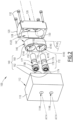
- connection assembly 100 is shown in section on the figure 1 , and in exploded perspective on the figure 2 .
- the connection assembly 100 is shown here in a configuration mounted on a support 110, which is not part of the connection assembly 100 but which contributes to its implementation.
- the support 110 includes a front face 112, which is considered flat.
- the "front” or “rear” directions are given with reference to a longitudinal axis, the front or “forward” longitudinal direction being turned in a direction of coupling of the connection assembly 100 with a plate 300.
- the plate 300 is described later in the description.
- the rear or “backward” longitudinal direction is opposite the forward longitudinal direction.
- the front longitudinal direction is oriented towards the right of the drawings, knowing that it may be otherwise in reality.
- a so-called “front” surface of the connection assembly 100 or the support 110 is turned in the front longitudinal direction while a so-called “rear” surface is turned in the rear longitudinal direction.
- the support 110 comprises a conduit, which is provided in the support 110 and which opens onto the front face 112 via two conduit outlets 114A and 114B.
- Each conduit outlet 114A or 114B here has a cylindrical shape of circular section centered on an outlet axis A114, which is perpendicular to the front face 112. In other words the outlet axes A114 associated with the conduit outlets 114A and 114B are parallel between them.
- connection assembly 100 also includes a cover 120 and a flange 140.
- the cover 120 is configured to be fixed to the support 110 in the mounted configuration of the connection assembly 100, in which the cover 120 forms with the support 110 a receiving housing V120 of the flange 140.
- the cover 120 has, in the first embodiment of the invention, a generally parallelepiped shape with a front wall 122, of rectangular shape, and a skirt 124.
- the front wall 122 is generally flat and comprises a front surface 126 and a rear surface 128, opposite the front surface 126.
- the rear surface 128 is oriented towards the support 110 and parallel to the front face 112 of the support 110.
- the skirt 124 extends at a periphery of the front wall 122 on the side of the rear surface 128.
- the receiving housing V120 here has a cylindrical shape of oblong section centered on an axis orthogonal to the front wall 122.
- Openings 130 are provided through the front wall 122, connecting the front surface 126 to the rear surface 128.
- the receiving housing V120 opens onto the front surface 126 via the openings 130.
- each opening 130 is aligned with a respective outlet axis A114, while the conduit outlets 114A and 114B open into the reception housing V120.
- the cover 120 is fixed to the support 110 by means of four fixing screws 132. Generally, the cover 120 is fixed to the support 110 without the possibility of movement relative to the support 110.
- the flange 140 includes a front surface 142, a rear surface 144 facing away from the front surface, and an outer peripheral surface 146, which connects the front surface 142 to the rear surface 144.
- the front 142 and rear surfaces 144 are here planar, parallel to each other and orthogonal to a longitudinal axis A140 of the flange 140.
- the external peripheral surface 146 delimits the flange 140 in a direction radial to the longitudinal axis A140.
- the front 142 and rear 144 surfaces extend parallel to a transverse plane P140, which is transverse to the longitudinal axis A140, in particular radial to the longitudinal axis A140, that is to say orthogonal to the longitudinal axis A140.
- the flange 140 here has a generally cylindrical external shape of oblong section taken in the transverse plane P140 and extending along the longitudinal axis A140.
- the flange 140 is received in the receiving housing V120, the rear surface 144 of the flange 140 being located facing the rear of the front face 112 of the support 110 in one direction longitudinal, that is to say in a direction parallel to the longitudinal axis A140, while the surface front 142 of the flange 140 is located facing the front of the rear surface 128 of the cover 120 in the longitudinal direction.
- the skirt 124 delimits, radially in the longitudinal direction, the receiving housing V120, while parallel to the longitudinal axis A140, the receiving housing V120 is delimited between the front face 112 of the support 110 and the rear surface 128 of the front wall 122 of the cover 120.
- the longitudinal axis A140 of the flange 140 is here parallel to the output axes A114.
- the front face 112 of the support 110 is therefore parallel to the rear surface 128 of the cover 120, the flange 140 being sandwiched between the front face 112 of the support 110 and the rear surface 128 of the cover 120.
- a clearance is provided around the flange 140 between the external peripheral surface 146 and the skirt 124, longitudinally between the flange 140 and the cover 120 and longitudinally between the flange 140 and the support 110, so that in the mounted configuration of the connection assembly 100, the flange 140 is movable relative to the cover 120 only according to a movement carried by the transverse plane P140.
- This movement can be a translation movement, in any direction parallel to the transverse plane P140, as well as a rotation movement around an axis of rotation parallel to the longitudinal axis A140. Translation and rotation movements can be combined. These movements are limited when the flange 140 abuts against the skirt 140.
- the flange 140 is shown in a so-called “neutral” position, in which the flange 140 is centered in the receiving housing V120.
- the flange 140 and the receiving volume V120 are preferably designed so that in the neutral position, a distance taken parallel to the transverse plane P140 between any point of the external peripheral surface 146 and the skirt 124 facing this point is constant. In other words, the clearance between the external peripheral surface 146 and the skirt 124 is constant all around the flange 140.
- the flange 140 delimits two internal orifices 150, which each pass through the flange 140 and which are each of revolution, centered on an orifice axis A150.
- the orifice axes A150 are parallel to each other and cross the transverse plane P140, in other words the transverse plane P140 is also transverse to the orifice axes A150.
- the “front” or “rear” directions given with reference to the longitudinal axis A140 are thus equivalent to the front or rear directions given with reference to the orifice axes A150.
- the front surface 142 therefore faces forward in a longitudinal direction parallel to the orifice axes A150, while the rear surface 144 faces rearward in a longitudinal direction parallel to the orifice axes A150.
- the axes orifice A150 are parallel to the longitudinal axis A140, that is to say orthogonal to the transverse plane P140.
- each internal orifice 150 opens onto the rear surface 144 of the flange 140 via a rear mouth 152.
- each rear mouth 152 diverges, towards the rear, from the axis of the orifice A150 of the corresponding internal orifice 150, each rear mouth 152 here having a frustoconical shape.
- each rear mouth 152 is arranged opposite a respective conduit outlet 114A or 114B parallel to the longitudinal axis A140.
- each rear mouth 152 is in fluid communication with the corresponding conduit outlet 114A or 114B.
- each internal orifice 150 is in fluid communication with a respective conduit outlet 114A or 114B towards the rear, and with an opening 130 towards the front.
- the flange 140 is made of several parts assembled together.
- the flange 140 here comprises a front body 160, and two rear bodies 162, each rear body cooperating with the front body 160 by nesting to form a respective internal orifice 150.
- Each rear body 162 is here housed in a respective cylindrical cavity V140 formed in the front body 160 of the flange 140.
- the front body 160 and the rear bodies 162 are thus simple to produce, for example by machining.
- the front body 160 comprises the front surface 142 of the flange 140, while each rear body 162 comprises a portion of the rear surface 144 of the flange 140.
- the front body 160 delimits a first volume V160 from each internal orifice 150, which opens onto the front surface 142.
- Each first volume V160 has a cylindrical shape of circular section, with a diameter D1, and is delimited by a first internal radial surface S160 , of diameter D1, centered on the corresponding orifice axis A150 and having a length L1, measured parallel to the orifice axis A150.
- the corresponding rear body 162 For each internal orifice 150, the corresponding rear body 162 comprises a first internal axial surface 163, which faces the front, which is perpendicular to the axis of the orifice 150 and which longitudinally delimits a second volume V162 of the orifice internal 150, into which the first volume V160 opens towards the rear.
- the second volume V162 is delimited longitudinally towards the front by a second internal axial surface 163' which is provided on the front body 160, perpendicular to the orifice axis 150 and turned towards the rear.
- each second volume V162 opens into a rear mouth 152.
- Each second volume V162 has a cylindrical shape of circular section, with a diameter D2, and is delimited by a second internal radial surface S162, of diameter D2, centered on the corresponding orifice axis A150 and having a length L2, measured parallel to the orifice axis A150.
- the length L2 also corresponds to the length taken parallel to the orifice axis A150 between the first internal axial surface 163 and the second internal axial surface 163'.
- the diameter D2 of the second volume V162 is greater than the diameter D1 of the first volume V160.
- the rear surface 144 On each rear body 162, the rear surface 144 comprises a rear groove 164, formed recessed in the rear surface 144 and having a closed circular contour centered on the corresponding orifice axis A150.
- Each rear groove 164 houses a first seal 166, here an O-ring.
- the first seals 166 are shown compressed against the flange 140 and the support 110.
- Each first seal 166 has an average diameter D166.
- the average diameter D166 is equal to ⁇ 20% to the diameter D2 of the second corresponding internal radial surface S162, which allows a more compact construction of connection assembly 100.
- each first seal 166 is interposed longitudinally between the flange 140 and the support 110 and surrounds, in a sealed manner, the rear mouth 152 of the corresponding internal orifice 150 and the corresponding conduit outlet 114A or 114B.
- each first seal 166 isolates the internal conduit 150 and the associated support conduit 110 from the receiving housing V120.
- Each rear mouth 152 is therefore permanently in fluid communication with the corresponding conduit outlet 114A or 114B.
- a minimum distance ⁇ 1 between the first two seals 166 is defined as being the smallest length, measured parallel to the transverse plane P140, between the two rear grooves 164.
- the flange 140 is shown in a so-called “neutral” position, in which the flange 140 is centered in the receiving housing V120.
- the flange 140 and the receiving volume V120 are designed so that in the neutral position of the flange 140, the clearance between the external peripheral surface 146 and the skirt 124 is substantially uniform all around the flange 140.
- On the top of the figure 1 we define a first minimum clearance J1 between the external peripheral surface 146 and the facing skirt 124, while on the bottom of the figure 1 , on the top of the figure 1 , we define a second minimum clearance J2 between the external peripheral surface 146 and the facing skirt 124.
- the games J1 and J2 are taken parallel to the transverse plane P140.
- the sum of the first and second games J1+J2 represents a maximum clearance of the flange 140 in the receiving housing V120 relative to the cover 120 in a direction parallel to the transverse plane P140.
- the flange 140 is in the neutral position and the first and second games J1 and J2 are equal.
- the flange 140 is offset from its neutral position, and the first and second games J1 and J2 are not equal.
- the minimum distance ⁇ 1 between the two first adjacent seals 166 is greater than the sum of the first and second games J1+J2, in other words greater than the maximum clearance of the flange 140 relative to the cover 120 in a direction parallel to the transverse plane P140. This avoids the covering of the surfaces swept by the first seals 166 during the movements of the flange 140 relative to the support 110, which prevents pollution of the surfaces by the fluids from the conduit outlets 114A and 114B. It is thus possible to circulate different fluids in each of the conduit outlets 114A or 114B.
- connection assembly 100 also comprises two fluidic connection elements 170.
- Each fluidic connection element 170 comprising a male body 172, which here has a hollow shape of revolution around a central axis, called male body axis A170.
- the male body 172 is crossed right through by an internal conduit 174 centered on the male body axis A170.
- Each male body 172 comprises a tubular front portion 176 with an outer radial surface 177, centered on the male body axis A170, and a rear portion 178, arranged opposite the tubular front portion 176 along the body axis male A170.
- each internal orifice 150 accommodates a respective fluidic connection element 170.
- Each rear portion 178 is received in a respective internal port 150, while each tubular front portion 176 is received partially in the internal port 150 and projects onto the front of the flange 140 and beyond the front surface 126 of the cover 120, out of the internal orifice 150 and the receiving housing V120, through a respective opening 130 of the cover 120.
- the cover 120 comprises at least as many openings 130 as the connection assembly comprises tubular front parts 176 More precisely, the rear part 178 is received in a second respective volume V162, the internal conduit 174 of each male body 172 thus being permanently in fluid communication with the rear mouth 152 of the corresponding internal orifice 150, while each. tubular front part 176 passes through the first volume V160 and protrudes onto the front of the flange 140, each tubular front part 176 being configured to be coupled with a complementary fluid connection element, described later.
- Each male body 172 is configured to abut, at the front, against the flange 140.
- the rear part 178 of each male body 172 comprises an external flange 180, which projects relative to the tubular front part 176 corresponding in a radial direction to the male body axis A170 of the corresponding male body 172.
- Each external flange 180 is housed in a second corresponding volume V162.
- Each external flange 180 comprises a front surface 182 and a rear surface 184 opposite the front surface 182.
- each external flange 180 In the mounted configuration of the connection assembly, for each external flange 180, the front surface 182 is arranged facing, in the front longitudinal direction, the front body 160.
- the rear surface 184 of the external flange 180 is arranged facing, in the rear longitudinal direction, of the rear body 162.
- the male body 172 is retained in the flange 140 in the front longitudinal direction. More precisely, for each male body 172, the first corresponding internal axial surface 163 of the flange 140 faces the front of the rear surface 184 of this male body 172.
- each external flange 180 is mounted according to the orifice axis 150 corresponding between the front body 160 and a rear body 162 respective of the flange 140.
- each male body 172 has the possibility of movement in the internal orifice 150 respective of the flange along the corresponding A150 orifice axis. Indeed, the length L2 of the volume V162 is greater than a length L3 taken parallel to the axis of orifice A150 between the front surface 182 and the rear surface 184 of the male body 172.
- a spring 196 of the fluidic connection element 170 pushes the front surface 182 into surface support against the second internal axial surface 163', while a longitudinal clearance exists between the rear surface 184 of the male body 172 and the first internal axial surface 163 all around the A150 port pin.
- the rear surface 184 is capable of bearing against the first internal axial surface 163 towards the rear.
- An external peripheral groove 186 is formed recessed in an external radial surface 187 of each external flange 180, each external peripheral groove 186 being centered on the male body axis A170 and being configured to receive a second seal 188, here an O-ring.
- the external radial surface 187 is located radially facing a second corresponding internal radial surface S162.
- a second seal 188 is interposed radially at the orifice axis A150, in compression and in a sealed manner, between each male body 172 and the second surface internal radial surface S162 of the flange 140, precisely between each external flange 180 and the second internal radial surface S162.
- Each male body 172 is received with assembly clearance in the corresponding internal orifice 150, so that this male body 172 has the possibility of inclination relative to the corresponding orifice axis A150.
- This possibility of inclination corresponds to a movement of the male body 172 in the internal orifice 150, with an elastic deformation of the second seal 188.
- the male body 172 In the uncoupled configuration of the connection assembly 100, the male body 172 is in a so-called “neutral” position in the corresponding internal orifice 150. In this neutral position, the corresponding male body axis A170 is substantially aligned with the corresponding orifice axis A150 and a tilt angle ⁇ of the male body axis A170 relative to the orifice axis A150 is null.
- the second seal 188 When the tilt angle ⁇ is non-zero, the second seal 188 is locally more compressed than in the neutral position of the male body 172, and the elastic return of the second seal 188 tends to cause the male body to return 172 towards its neutral position. It is understood that the maximum amplitude of the tilt angle ⁇ depends on the geometry of the parts and the assembly clearances which are present when the connection assembly 100 is in uncoupled configuration.
- the maximum amplitude of the tilt angle ⁇ depends on the radial clearances between the external radial surface 177 of the tubular front part 176 and the first internal radial surface S160 of the flange 140 facing radially to the longitudinal axis A140 , and/or depends on the radial clearances between the external radial surface 187 of the external flange 180 and the second internal radial surface S162 of the radially facing flange 140 and/or depends on the longitudinal clearances between the external flange 180 and the flange 140.
- the radial and longitudinal clearances between male body 172 and flange 140 are present all around the male body 172 in neutral position to allow adaptation of the position of the male body 172 in all directions around the orifice axis A150.
- the body axis A170 is intersecting with the orifice axis A150 corresponding to the level of the seal 188 associated along the orifice axis A150.
- the length L1 of the first internal radial surface S160 is greater than the length L2 of the second internal radial surface S162, to limit the maximum amplitude of the tilt angle ⁇ , preferably greater than 10% of the length L2 of the second internal radial surface S162.
- the maximum amplitude of the tilt angle ⁇ is less than 1° - 1 degree -.
- Each fluid connection element 170 further comprises a valve 190, which is received in the internal conduit 174 and which is movable, relative to the male body 172, between an advanced closing position, in which the valve 190 is in front abutment against an internal shoulder 192 of the tubular front part 176 and seals the internal conduit 174 in a sealed manner, and a rearward opening position, in which the valve 190 does not prevent the fluid passage in the internal conduit 174.
- the valve 190 is shown in the advanced closing position on the figures 1 And 3 and in the rearward opening position on the Figure 4 .
- Each fluidic connection element 170 also includes an interface ring 194, which is received in the internal conduit 174, and the spring 196, which is interposed between the valve 190 and the interface ring 194 to push the valve 190 towards its advanced closing position.
- the interface ring 194 bears, at the rear, against the flange 140 and the spring 196 bears on the interface ring 194. More precisely , the interface ring 194 here bears on the rear body 162 of the flange 140.
- the ring interface 194 is retained at the rear by a stop segment 198, which prevents the interface ring 194 from exiting the internal conduit 174 towards the rear.
- each spring 196 on the rear body 162 of the flange 140, via the corresponding interface ring 194 contributes to returning the corresponding connecting element 170 to its neutral position relative to the corresponding internal orifice 150, with the male body axis A170 merging with the corresponding orifice axis A150, in uncoupled configuration.
- the interface ring 194 has an internal diameter, which is preferably equal to a minimum internal diameter of the rear mouth 152 of the internal orifice 150, so as not to hinder the circulation of fluids in the internal conduit 174.
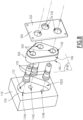
- thermoregulation assembly 200 is shown on the Figure 3 .
- the thermoregulation assembly 200 comprises the connection assembly 100, mounted on the support 110, and the plate 300, which includes complementary connection elements 370, which are each configured to mate with a respective connection element 170 of the connection assembly 100.
- the plate 300 therefore comprises here two complementary connection elements 370.
- the thermoregulation assembly 200 is configured for the circulation of a cooling fluid, also the assembly of thermoregulation 200 is here a cooling assembly, while the plate 300 is also called a “cold plate”.
- thermoregulation assembly 200 is intended for the circulation of a hot fluid, for example to heat an injection mold mounted on the plate 300.
- the implementation of the invention is independent of the temperature of the fluid intended to circulate through the connection assembly 100 and the thermoregulation assembly 200.
- connection assembly 100 When connecting the plate 300 to the connection assembly 100, the plate 300 is presented opposite the connection assembly 100. The front and rear directions relating to the plate 300 are therefore reversed relative to the assembly. connection 100. On the figures 3 And 4 , the front of plate 300 is located on the left of the drawings.
- the plate 300 comprises a support 310, with a front face 312, oriented towards the front face 112 of the support 110 when connecting the plate 300 to the connection assembly 100.
- the support 310 here comprises two threaded housings V310, of cylindrical shape centered along an axis orthogonal to the front face 312 of the support 310.
- the support 310 comprises a conduit, which is provided in the support 310 and which opens from a bottom of each threaded housing V310 via two conduit outlets 314A and 314B respective.
- Each conduit outlet 314A or 314B here has a frustoconical portion flared towards the front face 312.
- connection assembly 100 being here male elements with a male body 172
- complementary connection elements 370 are here female elements.
- Each complementary connection element 370 comprises a female body 372, which here has a hollow shape of revolution around a female body axis A370 and which is screwed into a respective threaded housing V310 in a sealed manner, with here radial interposition of a seal 302.
- Each female body 372 delimits an internal conduit 374, which communicates fluidly with a respective conduit outlet 314A or 314B of the support 310.
- Each complementary connection element 370 also comprises a pusher 376, housed in the corresponding internal conduit 374, each pusher 376 being secured in translation to the corresponding female body 372 by a stop segment 378, here located at a rear end of the pusher.
- Each pusher 376 comprises, at a front end opposite the rear end, a front part 377 forming a bulge in which a seal 379 is housed.
- Each female body 372 also includes an annular drawer 380, which is arranged radially to the axis of female body A370, in the internal conduit 374, between the pusher 376 and the female body 372.
- Each drawer 380 is movable in the internal conduit 374 between an advanced closing position of the internal conduit 374, in which the drawer 380 is in sealed contact with, on the one hand, the female body 372 by via a seal 381 and, on the other hand, the front part 377 of the pusher 376, via the seal 379, sealing the internal conduit 374 in a sealed manner, and a retracted opening position of the internal conduit 374, in which the drawer 380 does not prevent fluid circulation in the internal conduit 374.
- Each female body 372 also includes a spring 382, which is interposed between the drawer 380 and the corresponding pusher 376, each spring 382 pushing the drawer 380 towards its advanced closed position.
- the drawer 380 and the front part 377 of the pusher 376 each have a front face, which is located in the same front plane P380 when the drawer 380 is in the advanced closed position.
- Each female body 372 includes a flared mouth, here a conical mouth 384, which is arranged in front of the front plane P380.
- connection assembly 100 is brought closer to the connection assembly 100, parallel to the longitudinal axis A140, each conical mouth 384 being placed opposite, parallel to the longitudinal axis A140, a respective tubular front part 176.
- connection element 170 forms, with the corresponding complementary connection element 370, a pair of fluid connection elements 210.
- the thermoregulation assembly 200 therefore comprises two pairs of connection elements 210. Initially, as shown in THE figures 1 And 3 , the flange 140 is in its neutral position, which is not necessarily the case at the start of each coupling, and each connecting element 170 is in its neutral position.
- the A370 female body pin is aligned with a matching A170 male body pin.
- the misalignment ⁇ 2 at the start of the coupling between male body pins A170, if they were in neutral position, and female body pins A370 must be less than or equal to half of the maximum travel J1+J2 of the flange 140 in receiving slot V120.
- a first spacing D4 is defined as being the minimum distance between the body axes A170 of the two connection elements 170 on the flange 140, as well as a second spacing D5 as being the minimum distance between the female body axes A370 of the connection elements. additional connection 370 on plate 300.
- the thermoregulation assembly 200 has a spacing fault, equal to the absolute value of the difference between the first spacing D4 and the second spacing D5, that is to say
- the inclination of the connecting element(s) 170 in the flange 140 according to a tilt angle ⁇ makes it possible to compensate for a maximum spacing fault, of the order of 0.2 mm for example, the spacing fault
- each connection element 170 engages in the conical mouth 384 of a complementary connection element 370.
- each male body 172 s 'inclines if necessary, that is to say that the tilt angle ⁇ changes and takes a non-zero value.
- the flange 140 also moves if necessary relative to the cover 120, in the transverse plane P140, to compensate for the misalignment ⁇ 2 and allow the spacing defect to be taken into account
- This double adaptation on the side of the connecting elements 170 allows each male body 172 to come into contact with the drawer 280 and pushes it towards its rearward opening position, while jointly, each pusher 376 pushes the valve 190 towards its open position.
- the first seals 166 are in tight sliding with the front face 112 of the support 110, and the sections delimited by the first seals 166 which move do not overlap, even in the event of maximum travel.
- Each male body 172 seals with the female body 370 corresponding to the level of the joint 381.
- thermoregulation assembly 200 is then in a coupled configuration.
- is distributed between the two connecting elements 170, which are then both inclined in their internal orifices 150 relative to their neutral position, preferably but not necessarily equally with the same tilt angle ⁇ .
- a fluid can circulate through each pair of connecting elements 210 and through the cold plate 300 and the support 110.
- the fluid transported is water with a pressure of 5 to 20 bars for example.
- the pressure of the circulating fluid pushes the rear part 178 of the male body 172 into contact with the second internal axial surface 163'.
- the longitudinal distance between the front surface 182 of the external flange 180 and the second internal axial surface 163' is not uniform all around the A150 port axis.
- the front surface 182 is in longitudinal contact with the flange 140 in the lower part of the figure while the front surface 182 is detached from the second internal axial surface 163' in the upper part of the figure.
- the longitudinal distance between the rear surface 184 of the external flange 180 and the first internal axial surface 163 is non-zero but not uniform all around the orifice axis A150.
- thermoregulation assembly 200 We now describe a sequence for uncoupling the thermoregulation assembly 200.
- the plate 300 is moved away from the support 110.
- the valves 190 and drawers 380 pushed by the respective springs 196 and 382, each return to their respective closed position.
- the male bodies 172 emerge from the female bodies 372.
- connection assembly 100 If, in the coupled configuration of the connection assembly 100, the male bodies 172 had taken a position inclined relative to their neutral position, once the connection assembly 100 in the uncoupled configuration the male bodies 172 were returned to the neutral position under the action of the second seals 188.
- the flange 140 maintains the travel position taken during coupling.
- the elastic return of the male bodies 172 in the neutral position makes it possible to reduce the dimension of the conical mouths 384 radially to its longitudinal axis A370.
- connection assembly 400 conforming to a second embodiment of the invention is shown in Figure 6 .
- the elements similar to those of the first embodiment bear the same references and work the same way.
- the differences between the first and second embodiments are mainly described.
- connection assembly 400 comprises a flange 440 which is made in a single body 460.
- Each first seal 166 is housed directly into the rear surface 144 of the flange 440.
- the cover 120 includes only one opening 430, through which each tubular front part 176 opens out of the connection assembly 400.
- the tilting movements of the fluidic connection elements 170 in the flange 440 are represented schematically by the profile, in thin lines, of the fluidic connection elements 170 tilted on either side of their neutral position.
- This neutral position may be slightly misaligned with the corresponding orifice axis A150 when the elasticity of the seal 188 and/or the valve spring 196 fail to completely counter the gravity forces of the connecting element. fluidics 170.
- the possibility of inclination of the male bodies 172 is obtained by variation of the corresponding tilt angle ⁇ .
- connection assembly 500 conforming to a third embodiment of the invention is shown in figures 7 And 8 .
- the connection assembly 500 comprises a flange 540, made in a single body and in which three internal orifices 550 are provided, each receiving a male body 172.
- the three internal orifices 550 are here arranged in a triangle, and the flange 540 has a generally triangular cross section in the transverse plane P140.
- the connection assembly 500 is mounted on the support 110, in which a conduit is provided opening here via three conduit outlets 114A, 114B and 114C.
- the three conduit outlets 114A, 114B and 114C are each arranged opposite a respective internal orifice 550 in the front longitudinal direction, and are therefore here arranged in a triangle.
- the three conduit outlets 114A, 114B and 114C open onto the front face 112 of the support 110.
- the support 110 also includes a skirt 516, provided projecting relative to the front face 112 and which surrounds the three conduit outlets 114A, 114B and 114C.
- the connection assembly 500 comprises a cover 520, which here is reduced to a front wall 522, the cover 520 being attached to the support 110 in a mounted configuration of the connection assembly 500, in which the cover 520 fits with the support 110 a receiving housing V520 of the flange 540.
- the conduit outlets 114A, 114B and 114C open into the receiving housing V520, each conduit outlet 114A, 114B and 114C being associated with a respective internal orifice 550 of the flange 540.
- each male body 172 is mounted in the corresponding internal orifice 550 with the possibility of inclination relative to the corresponding orifice axis A150.
- each male body 172 is represented in neutral position. The tilt angle ⁇ being zero, it is not referenced on the figure 7 .
- the three internal orifices 550 are arranged in a triangle and the flange 540 has a substantially triangular section in the transverse plane P140.
- the three internal orifices are aligned, and the flange then has, for example, an oblong cross section.
- the flange comprises a front body and several rear bodies, each rear body being associated with a respective internal orifice.
- the rear bodies are part of the same rear element, which is made in one piece and which cooperates with the front body to provide the internal orifices in which the male bodies are received.
- the rear element then delimits the rear mouth of each of the internal orifices, as well as the rear surface of the flange.
- the orifice axes A150 are parallel to the longitudinal axis A140 of the flange 140, 440 or 540.
- the orifice axes A150 are inclined by a few degrees relative to the longitudinal axis A140, the orifice axes A150 remaining parallel to each other.
- the port axes A150 are inclined at an angle between ⁇ 20° with respect to the longitudinal axis A140.
- the orifice axes A150 form an angle of between 70° and 110° with the transverse plane P140. In all cases, the orifice axes A150 pass through the transverse plane P140.
- the seal interposed radially between the male body 172 and the flange 140, 440, 540 is housed in an internal peripheral groove provided on the flange and facing in the radial direction the longitudinal axis A140 with the external radial surface 187 of the external flange 180.
- the internal peripheral groove is formed for example in the second corresponding internal radial surface S162.
Landscapes
- Engineering & Computer Science (AREA)
- General Engineering & Computer Science (AREA)
- Mechanical Engineering (AREA)
- Quick-Acting Or Multi-Walled Pipe Joints (AREA)
- Physics & Mathematics (AREA)
- Thermal Sciences (AREA)
Claims (15)
- Verbindungsanordnung (100; 400; 500), die konfiguriert ist, um mit einer Platte (300) gekoppelt zu werden, und umfassend:- einen Flansch (140; 440; 540), der von mindestens zwei inneren Öffnungen (150; 550) durchquert wird, die jeweils auf einer Öffnungsachse (A150) zentriert sind, wobei die Öffnungsachsen parallel zueinander sind, der Flansch umfassend eine vordere Fläche (142), die in einer Längsrichtung parallel zu den Öffnungsachsen (A150) nach vorne gerichtet ist, und eine hintere Fläche (144), die nach hinten gerichtet ist, wobei die vordere und die hintere Fläche parallel zu einer Querebene (P140) sind, die quer zu den Öffnungsachsen (A150) ist,- einen Deckel (120; 520), der konfiguriert ist, um in einer montierten Konfiguration der Verbindungsanordnung an einem Träger (110) befestigt zu sein, der Träger umfassend Leitungsausgänge (114A, 114B; 114C),wobei jeder Leitungsausgang mit einer jeweiligen inneren Öffnung (150; 550) assoziiert ist,wobei:- sich die hintere Fläche (144) des Flanschs in einer montierten Konfiguration der Verbindungsanordnung gegenüber einer Vorderseite (112) des Trägers (110) in der Längsrichtung befindet, während sich die vordere Fläche (142) des Flanschs gegenüber einer hinteren Fläche (128) des Deckels in der Längsrichtung befindet,- jede innere Öffnung (150; 550) eine hintere Mündung (152) umfasst, die sich an der hinteren Fläche (144) des Flanschs öffnet und die in Fluidverbindung mit dem entsprechenden Leitungsausgang (114A, 114B; 114C) ist,- die Verbindungsanordnung ferner Folgendes umfasst:• erste Dichtungen (166), die in einer montierten Konfiguration der Verbindungsanordnung zwischen der hinteren Fläche (144) des Flanschs und der Vorderseite (112) des gegenüberliegenden Trägers eingefügt sind, wobei jede erste Dichtung einen jeweiligen Leitungsausgang (114A, 1148; 114C) und die assoziierte hintere Mündung (152) umgibt,• mindestens zwei Fluidverbindungselemente (170), wobei jedes Fluidverbindungselement einen Steckkörper (172) umfasst, der von einer inneren Leitung (174) durchquert wird, jeder Steckkörper umfassend einen röhrenförmigen vorderen Abschnitt (176) und einen hinteren Abschnitt (178),- wobei jeder hintere Abschnitt (178) in einer jeweiligen inneren Öffnung (150; 550) des Flanschs aufgenommen ist, während jeder röhrenförmige vordere Abschnitt (176) an der Vorderseite des Flanschs durch eine Öffnung (130; 430) des Deckels hervorsteht, wobei jeder Steckkörper (172) konfiguriert ist, um an der Vorderseite an dem Flansch anzuliegen,- jeder röhrenförmige Vorderteil (176) konfiguriert ist, um mit einem komplementären Fluidverbindungselement (370), das zu der Platte (300) gehört, gekoppelt zu werden,- der innere Kanal (174) von jedem Steckkörper ständig in Fluidverbindung mit der hinteren Mündung (152) der entsprechenden inneren Öffnung (150; 550) ist,dadurch gekennzeichnet, dass:- der Flansch (140; 440; 540) in der montierten Konfiguration der Verbindungsanordnung (100; 400; 500) in Bezug auf den Deckel (120; 520) nur gemäß einer Bewegung verschiebbar ist, die von der Querebene (P140) getragen wird,- die Verbindungsanordnung für jeden Steckkörper (172) eine zweite Dichtung (188) umfasst, die radial zwischen jeden männlichen Körper und einer inneren radialen Fläche (S162) der entsprechenden inneren Öffnung (150; 550) eingefügt ist,- jeder männliche Körper (172) in der entsprechenden inneren Öffnung (150; 550) mit Möglichkeit zur Neigung in Bezug auf die entsprechende Öffnungsachse (A150) montiert ist.
- Verbindungsanordnung (100; 400; 500) nach Anspruch 1, dadurch gekennzeichnet, dass in einer entkuppelten Konfiguration jeder Steckkörper (172) eine Möglichkeit zur Bewegung in der jeweiligen inneren Öffnung (150; 550) des Flanschs entlang der entsprechenden Öffnungsachse (A150) aufweist.
- Verbindungsanordnung (100) nach einem der Ansprüche 1 oder 2, dadurch gekennzeichnet, dass für jeden Steckkörper (172) eine innere axiale Fläche (163) des Flanschs (140), die die entsprechende innere Öffnung (150) begrenzt, einer hinteren Fläche (184) des Steckkörpers (172) nach vorne zugewandt ist.
- Verbindungsanordnung (100; 400; 500) nach einem der Ansprüche 1 bis 3, dadurch gekennzeichnet, dass der hintere Abschnitt (178) von jedem Steckkörper (172) einen äußeren Bund (180) umfasst, der in Bezug auf den vorderen rohrförmigen Abschnitt (176) in einer Richtung radial zu einer Mittelachse (A170) des entsprechenden Steckkörpers hervorstehend ausgebildet ist, und dass jede zweite Dichtung (188) radial zwischen dem Flansch (140; 440; 540) und dem entsprechenden äußeren Bund eingefügt ist.
- Verbindungsanordnung (100) nach Anspruch 4, dadurch gekennzeichnet, dass der Flansch (140) mindestens einen hinteren Körper (162) und einen vorderen Körper (160) umfasst, die ineinander aufgenommen sind, wobei der hintere Körper (162) die hintere Mündung (152) der inneren Öffnung (150) begrenzt, der vordere Körper (160) die vordere Fläche (142) des Flanschs begrenzt, wobei der äußere Bund (180) des Steckkörpers (172) entlang der Öffnungsachse (A150) zwischen dem vorderen Körper (160) und dem hinteren Körper (162) montiert ist.
- Verbindungsanordnung (100) nach Anspruch 5, dadurch gekennzeichnet, dass jede erste Dichtung (166) in Längsrichtung zwischen einer Oberfläche des hinteren Körpers (162), der die hintere Oberfläche (144) des Flansches (140) begrenzt, und dem Träger (110) eingefügt ist, wobei jede erste Dichtung (166) vorzugsweise in einer entsprechenden Nut (164) aufgenommen ist, die in dem hinteren Körper (162) ausgebildet ist.
- Verbindungsanordnung (100) nach einem der Ansprüche 5 oder 6, dadurch gekennzeichnet, dass jede zweite Dichtung (188) radial zwischen einer radialen Innenfläche (S162) der inneren Öffnung (150), die an dem hinteren Körper (162) des Flanschs (140) gebildet ist, und dem äußeren Flansch eingefügt ist, wobei jede zweite Dichtung (188) vorzugsweise in einer jeweiligen äußeren Umfangsnut (186) des äußeren Bunds (180) aufgenommen ist.
- Verbindungsanordnung (100) nach einem der Ansprüche 5 bis 7, dadurch gekennzeichnet, dass der Flansch (140) mindestens einen hinteren Körper (162) pro fluidischem Element (170) umfasst, wobei jeder hintere Körper in einem jeweiligen zylindrischen Hohlraum (V140) aufgenommen ist, der in dem vorderen Körper (160) des Flanschs (140) ausgebildet ist.
- Verbindungsanordnung (100; 400; 500) nach einem der Ansprüche 4 bis 8, dadurch gekennzeichnet,- dass die innere Öffnung (150; 550) ein erstes Volumen (V160) umfasst, das von einer ersten radialen Innenfläche (S160) des Flanschs (140; 440; 540) begrenzt wird, den röhrenförmigen vorderen Abschnitt (176) teilweise aufnimmt und nach vorne an der Vorderfläche (142) des Flanschs und nach hinten an einem zweiten Volumen (V162) der inneren Öffnung mündet, wobei das zweite Volumen von einer zweiten radialen Innenfläche (S162) des Flanschs begrenzt ist und den äußeren Bund (180) aufnimmt, und- dass eine Länge (L1) der ersten inneren radialen Fläche (S160) größer ist als eine Länge (L2) der zweiten inneren radialen Fläche (S162).
- Verbindungsanordnung (100) nach einem der Ansprüche 1 bis 9, dadurch gekennzeichnet, dass jedes fluidische Verbindungselement (170) Folgendes umfasst:- ein Ventil (190), das in dem inneren Kanal (174) in Bezug auf den Steckkörper (172) beweglich ist,- eine Feder (196), die in dem inneren Kanal untergebracht ist und das Ventil in eine geschlossene Position des inneren Kanals drückt, in der das Ventil in dichtendem Kontakt mit dem rohrförmigen vorderen Abschnitt (176) ist und den inneren Kanal verschließt, und- einen Schnittstellenring (194), der in dem inneren Kanal aufgenommen ist,und dass in einer montierten Konfiguration der Verbindungsanordnung (100; 400; 500) die Feder rückseitig an dem Schnittstellenring anliegt, der seinerseits rückseitig an dem Flansch (140) anliegt.
- Verbindungsanordnung (100) nach einem der Ansprüche 1 bis 10, dadurch gekennzeichnet, dass de hintere Mündung (152) von der Öffnungsachse (A150) der entsprechenden inneren Öffnung (150) nach hinten abweicht.
- Verbindungsanordnung (100) nach einem der Ansprüche 1 bis 11, dadurch gekennzeichnet, dass in einer montierten Konfiguration der Verbindungsanordnung ein minimaler Abstand (Δ1) zwischen zwei benachbarten ersten Dichtungen (166) größer ist als eine maximale Auslenkung (J1+J2) des Flanschs (140) in Bezug auf den Deckel (120) in einer Richtung parallel zu der Querebene (P140).
- Verbindungsanordnung (100; 400; 500) nach einem der Ansprüche 1 bis 12, dadurch gekennzeichnet, dass in einer entkuppelten Konfiguration jede zweite Dichtung (188) den entsprechenden Steckkörper (172) in eine Position vorspannt, in der eine Mittelachse (A170) des Steckkörpers (172) im Wesentlichen mit der entsprechenden Öffnungsachse (A150) ausgerichtet ist.
- Verbindungsanordnung (100; 400) nach einem der Ansprüche 1 bis 13, dadurch gekennzeichnet, dass der Deckel (120) Folgendes umfasst:- eine Schürze (124), die einen Aufnahmesitz (V120) für den Flansch (140; 440) radial zu der Längsrichtung begrenzt, und- eine Vorderwand (122), die mindestens so viele Öffnungen (130; 430) aufweist, wie die Verbindungsanordnung röhrenförmige vordere Abschnitte (176) umfasst.
- Temperaturregelanordnung (200), insbesondere zur Kühlung, umfassend:- einen Träger (110), in dem mindestens zwei Leitungsausgänge (114A, 114B; 114C) ausgebildet sind,- eine Verbindungsanordnung (100; 400; 500) nach einem der Ansprüche 1 bis 14, wobei der Deckel (120; 520) in der montierten Konfiguration der Verbindungsanordnung (100; 400; 500) an der Halterung befestigt ist, und- eine Platte (300), an der mindestens zwei komplementäre Verbindungselemente (370) befestigt sind, die jeweils konfiguriert sind, um mit einem jeweiligen fluidischen Verbindungselement (170) der Verbindungsanordnung zusammenpassen.
Applications Claiming Priority (1)
| Application Number | Priority Date | Filing Date | Title |
|---|---|---|---|
| FR2110074A FR3127542B1 (fr) | 2021-09-24 | 2021-09-24 | Ensemble de connexion et ensemble de refroidissement |
Publications (2)
| Publication Number | Publication Date |
|---|---|
| EP4155596A1 EP4155596A1 (de) | 2023-03-29 |
| EP4155596B1 true EP4155596B1 (de) | 2024-06-19 |
Family
ID=78049477
Family Applications (1)
| Application Number | Title | Priority Date | Filing Date |
|---|---|---|---|
| EP22197330.8A Active EP4155596B1 (de) | 2021-09-24 | 2022-09-23 | Verbindungsanordnung und kühlanordnung |
Country Status (4)
| Country | Link |
|---|---|
| US (1) | US11746942B2 (de) |
| EP (1) | EP4155596B1 (de) |
| CN (1) | CN115854154A (de) |
| FR (1) | FR3127542B1 (de) |
Families Citing this family (11)
| Publication number | Priority date | Publication date | Assignee | Title |
|---|---|---|---|---|
| CN109771048B (zh) * | 2019-01-16 | 2024-08-20 | 美昕医疗器械(上海)有限公司 | 一种耗材盒 |
| FR3097565B1 (fr) * | 2019-06-19 | 2022-08-12 | Staubli Sa Ets | Machine textile, métier à tisser comportant une telle machine textile et procédés associés |
| CN110500463B (zh) * | 2019-07-17 | 2021-08-20 | 华为技术有限公司 | 一种接头、冷却系统和计算机装置 |
| WO2022180569A1 (en) * | 2021-02-26 | 2022-09-01 | Danfoss Power Solutions Ii Technology A/S | Blind mate coupling with a self centering mechanism |
| GB2616300B (en) * | 2022-03-04 | 2025-05-14 | Cejn Ab | System for centralizing a quick connect nipple |
| CN117628294A (zh) * | 2022-08-17 | 2024-03-01 | 瑞肯耐特流体控制系统(镇江)有限公司 | 连接器装置 |
| US12455032B2 (en) * | 2022-11-28 | 2025-10-28 | Parker-Hannifin Corporation | Blind mate fluid coupling with misalignment compensation |
| EP4495471A1 (de) * | 2023-07-20 | 2025-01-22 | Goodrich Corporation | Wasseranschlussverschlussanordnung |
| FR3156876B1 (fr) | 2023-12-15 | 2026-02-13 | Staubli Faverges | Dispositif de raccordement fluidique et ensemble de raccordement fluidique comprenant un tel dispositif de raccordement fluidique |
| TWI890535B (zh) * | 2024-07-29 | 2025-07-11 | 富世達股份有限公司 | 接頭浮動固定座減少摩擦結構 |
| US12504108B1 (en) * | 2025-02-11 | 2025-12-23 | Fositek Corporation | Joint floating fixed seat structure |
Family Cites Families (16)
| Publication number | Priority date | Publication date | Assignee | Title |
|---|---|---|---|---|
| US3508580A (en) * | 1967-09-12 | 1970-04-28 | Srm Co | Fluid-tight coupling for laterally misaligned conduits |
| US3645294A (en) * | 1970-10-19 | 1972-02-29 | Aeroquip Corp | Self-sealing coupling |
| US4171559A (en) * | 1976-10-21 | 1979-10-23 | Stratoflex, Inc. | Method of making connections in pneumatic and hydraulic systems and testing such systems |
| US5322330A (en) * | 1988-05-05 | 1994-06-21 | Preece Incorporated | Quick disconnect with a position compensating seal |
| US4886301A (en) * | 1988-05-05 | 1989-12-12 | Preece Incorporated | Quick disconnect with a position compensating seal |
| US5354103A (en) * | 1994-01-28 | 1994-10-11 | Eaton Corporation | Quick connect conduit coupling |
| US20040074541A1 (en) * | 2002-07-04 | 2004-04-22 | Andrew Sharpe | Flow connector |
| FR2919706B1 (fr) * | 2007-07-30 | 2009-10-09 | Staubli Faverges Sca | Element de raccord rapide et raccord rapide comprenant un tel element |
| FR2986310B1 (fr) * | 2012-01-31 | 2014-03-21 | Staubli Sa Ets | Systeme de refroidissement avec conduit de circulation de fluide caloporteur |
| US20130312846A1 (en) * | 2012-05-25 | 2013-11-28 | André Sloth Eriksen | Fluid connector for a cooling system |
| CA2896454C (en) | 2014-07-08 | 2021-12-07 | Staubli Faverges | Connecting plug, cooling circuit equipped with such a connecting plug and method for connecting such a cooling circuit and a cold plate |
| US9351428B2 (en) * | 2014-08-29 | 2016-05-24 | Lenovo Enterprise Solutions (Singapore) Pte. Ltd. | Blind docking apparatus to enable liquid cooling in compute nodes |
| CN207112176U (zh) * | 2017-04-10 | 2018-03-16 | 史陶比尔法万举 | 公流体联接元件及不对准容错流体联接器 |
| WO2022180569A1 (en) * | 2021-02-26 | 2022-09-01 | Danfoss Power Solutions Ii Technology A/S | Blind mate coupling with a self centering mechanism |
| FR3122474B1 (fr) * | 2021-04-29 | 2023-05-05 | Staubli Sa Ets | Elément mâle ou femelle de raccord fluidique et raccord fluidique comprenant un tel élément |
| US11815214B2 (en) * | 2021-06-29 | 2023-11-14 | Parker-Hannifin Corporation | Blind mate fluid coupling with misalignment compensation |
-
2021
- 2021-09-24 FR FR2110074A patent/FR3127542B1/fr active Active
-
2022
- 2022-09-16 US US17/946,249 patent/US11746942B2/en active Active
- 2022-09-22 CN CN202211157863.0A patent/CN115854154A/zh active Pending
- 2022-09-23 EP EP22197330.8A patent/EP4155596B1/de active Active
Also Published As
| Publication number | Publication date |
|---|---|
| EP4155596A1 (de) | 2023-03-29 |
| CN115854154A (zh) | 2023-03-28 |
| US20230094260A1 (en) | 2023-03-30 |
| FR3127542A1 (fr) | 2023-03-31 |
| US11746942B2 (en) | 2023-09-05 |
| FR3127542B1 (fr) | 2023-10-13 |
Similar Documents
| Publication | Publication Date | Title |
|---|---|---|
| EP4155596B1 (de) | Verbindungsanordnung und kühlanordnung | |
| EP2048425B1 (de) | Anschlussbuchse und eine solche Buchse umfassender Anschluss | |
| EP4083487A1 (de) | Stecker oder buchse eines fluidanschlusses und fluidanschluss mit einem solchen stecker bzw. mit einer solchen buchse | |
| EP3581836B1 (de) | Flüssigkeitskupplung | |
| FR2861159A1 (fr) | Raccord rapide pour la jonction amovible de deux canalisations et utilisation d'un tel raccord | |
| EP3184870B1 (de) | Buchse eines schnellanschlusses, und eine solche buchse umfassender schnellanschluss | |
| FR2913089A1 (fr) | Element de raccord a soupape d'obturation et raccord incorporant un tel element | |
| EP3599408B1 (de) | Schnellkupplung für die lösbare verbindung von zwei rohren, durch die eine flüssigkeit unter druck fliesst | |
| EP4056883B1 (de) | Buchse eines schnellanschlusses, und schnellanschluss, der eine solche buchse und einen entsprechenden stecker umfasst | |
| EP3196526B1 (de) | Schnellkupplung für die lösbare verbindung von leitungen für fluide unter druck | |
| CA1261311A (fr) | Dispositif d'obturation pour conduite vehiculant un fluide | |
| EP3742037B1 (de) | Anschlussbuchse eines fluidanschlusses, untereinheit zum anschliessen und anschluss, der eine solche anschlussbuchse umfasst | |
| FR3156876A1 (fr) | Dispositif de raccordement fluidique et ensemble de raccordement fluidique comprenant un tel dispositif de raccordement fluidique | |
| EP4166836A1 (de) | Schnellkupplung und verbindungsanordnung mit einer solchen schnellkupplung | |
| FR3146185A1 (fr) | Élément femelle de raccord rapide, et raccord rapide associé | |
| EP4491926B1 (de) | Fluidanschlusselement und fluidanschluss dafür | |
| EP3599409B1 (de) | Schnellkupplung für die lösbare verbindung von zwei leitungen, durch die eine flüssigkeit unter druck fliesst | |
| EP4336080B1 (de) | Schnellkupplungsbuchse | |
| WO2015145027A1 (fr) | Interface améliorée pour une vanne de conduit de fluide cryogenique. | |
| EP3798490B1 (de) | Fluidanschlusselement | |
| EP4419821A1 (de) | Kükenventil |
Legal Events
| Date | Code | Title | Description |
|---|---|---|---|
| PUAI | Public reference made under article 153(3) epc to a published international application that has entered the european phase |
Free format text: ORIGINAL CODE: 0009012 |
|
| STAA | Information on the status of an ep patent application or granted ep patent |
Free format text: STATUS: THE APPLICATION HAS BEEN PUBLISHED |
|
| AK | Designated contracting states |
Kind code of ref document: A1 Designated state(s): AL AT BE BG CH CY CZ DE DK EE ES FI FR GB GR HR HU IE IS IT LI LT LU LV MC MK MT NL NO PL PT RO RS SE SI SK SM TR |
|
| STAA | Information on the status of an ep patent application or granted ep patent |
Free format text: STATUS: REQUEST FOR EXAMINATION WAS MADE |
|
| 17P | Request for examination filed |
Effective date: 20230904 |
|
| RBV | Designated contracting states (corrected) |
Designated state(s): AL AT BE BG CH CY CZ DE DK EE ES FI FR GB GR HR HU IE IS IT LI LT LU LV MC MK MT NL NO PL PT RO RS SE SI SK SM TR |
|
| GRAP | Despatch of communication of intention to grant a patent |
Free format text: ORIGINAL CODE: EPIDOSNIGR1 |
|
| STAA | Information on the status of an ep patent application or granted ep patent |
Free format text: STATUS: GRANT OF PATENT IS INTENDED |
|
| RIC1 | Information provided on ipc code assigned before grant |
Ipc: F16L 41/12 20060101ALI20240111BHEP Ipc: F16L 37/56 20060101AFI20240111BHEP |
|
| INTG | Intention to grant announced |
Effective date: 20240129 |
|
| GRAS | Grant fee paid |
Free format text: ORIGINAL CODE: EPIDOSNIGR3 |
|
| GRAA | (expected) grant |
Free format text: ORIGINAL CODE: 0009210 |
|
| STAA | Information on the status of an ep patent application or granted ep patent |
Free format text: STATUS: THE PATENT HAS BEEN GRANTED |
|
| AK | Designated contracting states |
Kind code of ref document: B1 Designated state(s): AL AT BE BG CH CY CZ DE DK EE ES FI FR GB GR HR HU IE IS IT LI LT LU LV MC MK MT NL NO PL PT RO RS SE SI SK SM TR |
|
| REG | Reference to a national code |
Ref country code: GB Ref legal event code: FG4D Free format text: NOT ENGLISH |
|
| REG | Reference to a national code |
Ref country code: CH Ref legal event code: EP |
|
| REG | Reference to a national code |
Ref country code: DE Ref legal event code: R096 Ref document number: 602022004020 Country of ref document: DE |
|
| PG25 | Lapsed in a contracting state [announced via postgrant information from national office to epo] |
Ref country code: BG Free format text: LAPSE BECAUSE OF FAILURE TO SUBMIT A TRANSLATION OF THE DESCRIPTION OR TO PAY THE FEE WITHIN THE PRESCRIBED TIME-LIMIT Effective date: 20240619 |
|
| PG25 | Lapsed in a contracting state [announced via postgrant information from national office to epo] |
Ref country code: FI Free format text: LAPSE BECAUSE OF FAILURE TO SUBMIT A TRANSLATION OF THE DESCRIPTION OR TO PAY THE FEE WITHIN THE PRESCRIBED TIME-LIMIT Effective date: 20240619 Ref country code: HR Free format text: LAPSE BECAUSE OF FAILURE TO SUBMIT A TRANSLATION OF THE DESCRIPTION OR TO PAY THE FEE WITHIN THE PRESCRIBED TIME-LIMIT Effective date: 20240619 |
|
| REG | Reference to a national code |
Ref country code: LT Ref legal event code: MG9D |
|
| PG25 | Lapsed in a contracting state [announced via postgrant information from national office to epo] |
Ref country code: GR Free format text: LAPSE BECAUSE OF FAILURE TO SUBMIT A TRANSLATION OF THE DESCRIPTION OR TO PAY THE FEE WITHIN THE PRESCRIBED TIME-LIMIT Effective date: 20240920 |
|
| P01 | Opt-out of the competence of the unified patent court (upc) registered |
Free format text: CASE NUMBER: APP_51804/2024 Effective date: 20240914 |
|
| REG | Reference to a national code |
Ref country code: NL Ref legal event code: MP Effective date: 20240619 |
|
| PG25 | Lapsed in a contracting state [announced via postgrant information from national office to epo] |
Ref country code: LV Free format text: LAPSE BECAUSE OF FAILURE TO SUBMIT A TRANSLATION OF THE DESCRIPTION OR TO PAY THE FEE WITHIN THE PRESCRIBED TIME-LIMIT Effective date: 20240619 |
|
| PG25 | Lapsed in a contracting state [announced via postgrant information from national office to epo] |
Ref country code: NO Free format text: LAPSE BECAUSE OF FAILURE TO SUBMIT A TRANSLATION OF THE DESCRIPTION OR TO PAY THE FEE WITHIN THE PRESCRIBED TIME-LIMIT Effective date: 20240919 Ref country code: LV Free format text: LAPSE BECAUSE OF FAILURE TO SUBMIT A TRANSLATION OF THE DESCRIPTION OR TO PAY THE FEE WITHIN THE PRESCRIBED TIME-LIMIT Effective date: 20240619 Ref country code: HR Free format text: LAPSE BECAUSE OF FAILURE TO SUBMIT A TRANSLATION OF THE DESCRIPTION OR TO PAY THE FEE WITHIN THE PRESCRIBED TIME-LIMIT Effective date: 20240619 Ref country code: GR Free format text: LAPSE BECAUSE OF FAILURE TO SUBMIT A TRANSLATION OF THE DESCRIPTION OR TO PAY THE FEE WITHIN THE PRESCRIBED TIME-LIMIT Effective date: 20240920 Ref country code: FI Free format text: LAPSE BECAUSE OF FAILURE TO SUBMIT A TRANSLATION OF THE DESCRIPTION OR TO PAY THE FEE WITHIN THE PRESCRIBED TIME-LIMIT Effective date: 20240619 Ref country code: BG Free format text: LAPSE BECAUSE OF FAILURE TO SUBMIT A TRANSLATION OF THE DESCRIPTION OR TO PAY THE FEE WITHIN THE PRESCRIBED TIME-LIMIT Effective date: 20240619 Ref country code: RS Free format text: LAPSE BECAUSE OF FAILURE TO SUBMIT A TRANSLATION OF THE DESCRIPTION OR TO PAY THE FEE WITHIN THE PRESCRIBED TIME-LIMIT Effective date: 20240919 |
|
| PG25 | Lapsed in a contracting state [announced via postgrant information from national office to epo] |
Ref country code: NL Free format text: LAPSE BECAUSE OF FAILURE TO SUBMIT A TRANSLATION OF THE DESCRIPTION OR TO PAY THE FEE WITHIN THE PRESCRIBED TIME-LIMIT Effective date: 20240619 |
|
| REG | Reference to a national code |
Ref country code: AT Ref legal event code: MK05 Ref document number: 1696108 Country of ref document: AT Kind code of ref document: T Effective date: 20240619 |
|
| PG25 | Lapsed in a contracting state [announced via postgrant information from national office to epo] |
Ref country code: NL Free format text: LAPSE BECAUSE OF FAILURE TO SUBMIT A TRANSLATION OF THE DESCRIPTION OR TO PAY THE FEE WITHIN THE PRESCRIBED TIME-LIMIT Effective date: 20240619 |
|
| PG25 | Lapsed in a contracting state [announced via postgrant information from national office to epo] |
Ref country code: PT Free format text: LAPSE BECAUSE OF FAILURE TO SUBMIT A TRANSLATION OF THE DESCRIPTION OR TO PAY THE FEE WITHIN THE PRESCRIBED TIME-LIMIT Effective date: 20241021 |
|
| PG25 | Lapsed in a contracting state [announced via postgrant information from national office to epo] |
Ref country code: PT Free format text: LAPSE BECAUSE OF FAILURE TO SUBMIT A TRANSLATION OF THE DESCRIPTION OR TO PAY THE FEE WITHIN THE PRESCRIBED TIME-LIMIT Effective date: 20241021 |
|
| PG25 | Lapsed in a contracting state [announced via postgrant information from national office to epo] |
Ref country code: PL Free format text: LAPSE BECAUSE OF FAILURE TO SUBMIT A TRANSLATION OF THE DESCRIPTION OR TO PAY THE FEE WITHIN THE PRESCRIBED TIME-LIMIT Effective date: 20240619 |
|
| PG25 | Lapsed in a contracting state [announced via postgrant information from national office to epo] |
Ref country code: EE Free format text: LAPSE BECAUSE OF FAILURE TO SUBMIT A TRANSLATION OF THE DESCRIPTION OR TO PAY THE FEE WITHIN THE PRESCRIBED TIME-LIMIT Effective date: 20240619 |
|
| PG25 | Lapsed in a contracting state [announced via postgrant information from national office to epo] |
Ref country code: IS Free format text: LAPSE BECAUSE OF FAILURE TO SUBMIT A TRANSLATION OF THE DESCRIPTION OR TO PAY THE FEE WITHIN THE PRESCRIBED TIME-LIMIT Effective date: 20241019 Ref country code: AT Free format text: LAPSE BECAUSE OF FAILURE TO SUBMIT A TRANSLATION OF THE DESCRIPTION OR TO PAY THE FEE WITHIN THE PRESCRIBED TIME-LIMIT Effective date: 20240619 |
|
| PG25 | Lapsed in a contracting state [announced via postgrant information from national office to epo] |
Ref country code: CZ Free format text: LAPSE BECAUSE OF FAILURE TO SUBMIT A TRANSLATION OF THE DESCRIPTION OR TO PAY THE FEE WITHIN THE PRESCRIBED TIME-LIMIT Effective date: 20240619 |
|
| PG25 | Lapsed in a contracting state [announced via postgrant information from national office to epo] |
Ref country code: RO Free format text: LAPSE BECAUSE OF FAILURE TO SUBMIT A TRANSLATION OF THE DESCRIPTION OR TO PAY THE FEE WITHIN THE PRESCRIBED TIME-LIMIT Effective date: 20240619 Ref country code: SK Free format text: LAPSE BECAUSE OF FAILURE TO SUBMIT A TRANSLATION OF THE DESCRIPTION OR TO PAY THE FEE WITHIN THE PRESCRIBED TIME-LIMIT Effective date: 20240619 |
|
| PG25 | Lapsed in a contracting state [announced via postgrant information from national office to epo] |
Ref country code: ES Free format text: LAPSE BECAUSE OF FAILURE TO SUBMIT A TRANSLATION OF THE DESCRIPTION OR TO PAY THE FEE WITHIN THE PRESCRIBED TIME-LIMIT Effective date: 20240619 Ref country code: SM Free format text: LAPSE BECAUSE OF FAILURE TO SUBMIT A TRANSLATION OF THE DESCRIPTION OR TO PAY THE FEE WITHIN THE PRESCRIBED TIME-LIMIT Effective date: 20240619 |
|
| PG25 | Lapsed in a contracting state [announced via postgrant information from national office to epo] |
Ref country code: SM Free format text: LAPSE BECAUSE OF FAILURE TO SUBMIT A TRANSLATION OF THE DESCRIPTION OR TO PAY THE FEE WITHIN THE PRESCRIBED TIME-LIMIT Effective date: 20240619 Ref country code: SK Free format text: LAPSE BECAUSE OF FAILURE TO SUBMIT A TRANSLATION OF THE DESCRIPTION OR TO PAY THE FEE WITHIN THE PRESCRIBED TIME-LIMIT Effective date: 20240619 Ref country code: RO Free format text: LAPSE BECAUSE OF FAILURE TO SUBMIT A TRANSLATION OF THE DESCRIPTION OR TO PAY THE FEE WITHIN THE PRESCRIBED TIME-LIMIT Effective date: 20240619 Ref country code: PL Free format text: LAPSE BECAUSE OF FAILURE TO SUBMIT A TRANSLATION OF THE DESCRIPTION OR TO PAY THE FEE WITHIN THE PRESCRIBED TIME-LIMIT Effective date: 20240619 Ref country code: IS Free format text: LAPSE BECAUSE OF FAILURE TO SUBMIT A TRANSLATION OF THE DESCRIPTION OR TO PAY THE FEE WITHIN THE PRESCRIBED TIME-LIMIT Effective date: 20241019 Ref country code: ES Free format text: LAPSE BECAUSE OF FAILURE TO SUBMIT A TRANSLATION OF THE DESCRIPTION OR TO PAY THE FEE WITHIN THE PRESCRIBED TIME-LIMIT Effective date: 20240619 Ref country code: EE Free format text: LAPSE BECAUSE OF FAILURE TO SUBMIT A TRANSLATION OF THE DESCRIPTION OR TO PAY THE FEE WITHIN THE PRESCRIBED TIME-LIMIT Effective date: 20240619 Ref country code: CZ Free format text: LAPSE BECAUSE OF FAILURE TO SUBMIT A TRANSLATION OF THE DESCRIPTION OR TO PAY THE FEE WITHIN THE PRESCRIBED TIME-LIMIT Effective date: 20240619 Ref country code: AT Free format text: LAPSE BECAUSE OF FAILURE TO SUBMIT A TRANSLATION OF THE DESCRIPTION OR TO PAY THE FEE WITHIN THE PRESCRIBED TIME-LIMIT Effective date: 20240619 |
|
| PG25 | Lapsed in a contracting state [announced via postgrant information from national office to epo] |
Ref country code: IT Free format text: LAPSE BECAUSE OF FAILURE TO SUBMIT A TRANSLATION OF THE DESCRIPTION OR TO PAY THE FEE WITHIN THE PRESCRIBED TIME-LIMIT Effective date: 20240619 |
|
| REG | Reference to a national code |
Ref country code: DE Ref legal event code: R097 Ref document number: 602022004020 Country of ref document: DE |
|
| PG25 | Lapsed in a contracting state [announced via postgrant information from national office to epo] |
Ref country code: DK Free format text: LAPSE BECAUSE OF FAILURE TO SUBMIT A TRANSLATION OF THE DESCRIPTION OR TO PAY THE FEE WITHIN THE PRESCRIBED TIME-LIMIT Effective date: 20240619 |
|
| PG25 | Lapsed in a contracting state [announced via postgrant information from national office to epo] |
Ref country code: MC Free format text: LAPSE BECAUSE OF FAILURE TO SUBMIT A TRANSLATION OF THE DESCRIPTION OR TO PAY THE FEE WITHIN THE PRESCRIBED TIME-LIMIT Effective date: 20240619 |
|
| PLBE | No opposition filed within time limit |
Free format text: ORIGINAL CODE: 0009261 |
|
| STAA | Information on the status of an ep patent application or granted ep patent |
Free format text: STATUS: NO OPPOSITION FILED WITHIN TIME LIMIT |
|
| PG25 | Lapsed in a contracting state [announced via postgrant information from national office to epo] |
Ref country code: LU Free format text: LAPSE BECAUSE OF NON-PAYMENT OF DUE FEES Effective date: 20240923 |
|
| 26N | No opposition filed |
Effective date: 20250320 |
|
| REG | Reference to a national code |
Ref country code: BE Ref legal event code: MM Effective date: 20240930 |
|
| PG25 | Lapsed in a contracting state [announced via postgrant information from national office to epo] |
Ref country code: BE Free format text: LAPSE BECAUSE OF NON-PAYMENT OF DUE FEES Effective date: 20240930 |
|
| PG25 | Lapsed in a contracting state [announced via postgrant information from national office to epo] |
Ref country code: IE Free format text: LAPSE BECAUSE OF NON-PAYMENT OF DUE FEES Effective date: 20240923 |
|
| PG25 | Lapsed in a contracting state [announced via postgrant information from national office to epo] |
Ref country code: SE Free format text: LAPSE BECAUSE OF FAILURE TO SUBMIT A TRANSLATION OF THE DESCRIPTION OR TO PAY THE FEE WITHIN THE PRESCRIBED TIME-LIMIT Effective date: 20240619 |
|
| REG | Reference to a national code |
Ref country code: CH Ref legal event code: U11 Free format text: ST27 STATUS EVENT CODE: U-0-0-U10-U11 (AS PROVIDED BY THE NATIONAL OFFICE) Effective date: 20251001 |
|
| PGFP | Annual fee paid to national office [announced via postgrant information from national office to epo] |
Ref country code: DE Payment date: 20250929 Year of fee payment: 4 |
|
| PGFP | Annual fee paid to national office [announced via postgrant information from national office to epo] |
Ref country code: TR Payment date: 20250908 Year of fee payment: 4 |
|
| PGFP | Annual fee paid to national office [announced via postgrant information from national office to epo] |
Ref country code: FR Payment date: 20250925 Year of fee payment: 4 |
|
| PGFP | Annual fee paid to national office [announced via postgrant information from national office to epo] |
Ref country code: CH Payment date: 20251001 Year of fee payment: 4 |
|
| PG25 | Lapsed in a contracting state [announced via postgrant information from national office to epo] |
Ref country code: CY Free format text: LAPSE BECAUSE OF FAILURE TO SUBMIT A TRANSLATION OF THE DESCRIPTION OR TO PAY THE FEE WITHIN THE PRESCRIBED TIME-LIMIT; INVALID AB INITIO Effective date: 20220923 |