EP4155583B1 - Achsanordnung mit einem getriebemodul - Google Patents
Achsanordnung mit einem getriebemodul Download PDFInfo
- Publication number
- EP4155583B1 EP4155583B1 EP22206702.7A EP22206702A EP4155583B1 EP 4155583 B1 EP4155583 B1 EP 4155583B1 EP 22206702 A EP22206702 A EP 22206702A EP 4155583 B1 EP4155583 B1 EP 4155583B1
- Authority
- EP
- European Patent Office
- Prior art keywords
- lubricant
- transmission housing
- countershaft
- transmission
- housing
- Prior art date
- Legal status (The legal status is an assumption and is not a legal conclusion. Google has not performed a legal analysis and makes no representation as to the accuracy of the status listed.)
- Active
Links
Images


Classifications
-
- F—MECHANICAL ENGINEERING; LIGHTING; HEATING; WEAPONS; BLASTING
- F16—ENGINEERING ELEMENTS AND UNITS; GENERAL MEASURES FOR PRODUCING AND MAINTAINING EFFECTIVE FUNCTIONING OF MACHINES OR INSTALLATIONS; THERMAL INSULATION IN GENERAL
- F16H—GEARING
- F16H57/00—General details of gearing
- F16H57/04—Features relating to lubrication or cooling or heating
- F16H57/0434—Features relating to lubrication or cooling or heating relating to lubrication supply, e.g. pumps; Pressure control
- F16H57/0445—Features relating to lubrication or cooling or heating relating to lubrication supply, e.g. pumps; Pressure control for supply of different gearbox casings or sections
-
- B—PERFORMING OPERATIONS; TRANSPORTING
- B60—VEHICLES IN GENERAL
- B60K—ARRANGEMENT OR MOUNTING OF PROPULSION UNITS OR OF TRANSMISSIONS IN VEHICLES; ARRANGEMENT OR MOUNTING OF PLURAL DIVERSE PRIME-MOVERS IN VEHICLES; AUXILIARY DRIVES FOR VEHICLES; INSTRUMENTATION OR DASHBOARDS FOR VEHICLES; ARRANGEMENTS IN CONNECTION WITH COOLING, AIR INTAKE, GAS EXHAUST OR FUEL SUPPLY OF PROPULSION UNITS IN VEHICLES
- B60K1/00—Arrangement or mounting of electrical propulsion units
-
- B—PERFORMING OPERATIONS; TRANSPORTING
- B60—VEHICLES IN GENERAL
- B60K—ARRANGEMENT OR MOUNTING OF PROPULSION UNITS OR OF TRANSMISSIONS IN VEHICLES; ARRANGEMENT OR MOUNTING OF PLURAL DIVERSE PRIME-MOVERS IN VEHICLES; AUXILIARY DRIVES FOR VEHICLES; INSTRUMENTATION OR DASHBOARDS FOR VEHICLES; ARRANGEMENTS IN CONNECTION WITH COOLING, AIR INTAKE, GAS EXHAUST OR FUEL SUPPLY OF PROPULSION UNITS IN VEHICLES
- B60K17/00—Arrangement or mounting of transmissions in vehicles
- B60K17/02—Arrangement or mounting of transmissions in vehicles characterised by arrangement, location, or kind of clutch
-
- B—PERFORMING OPERATIONS; TRANSPORTING
- B60—VEHICLES IN GENERAL
- B60K—ARRANGEMENT OR MOUNTING OF PROPULSION UNITS OR OF TRANSMISSIONS IN VEHICLES; ARRANGEMENT OR MOUNTING OF PLURAL DIVERSE PRIME-MOVERS IN VEHICLES; AUXILIARY DRIVES FOR VEHICLES; INSTRUMENTATION OR DASHBOARDS FOR VEHICLES; ARRANGEMENTS IN CONNECTION WITH COOLING, AIR INTAKE, GAS EXHAUST OR FUEL SUPPLY OF PROPULSION UNITS IN VEHICLES
- B60K17/00—Arrangement or mounting of transmissions in vehicles
- B60K17/04—Arrangement or mounting of transmissions in vehicles characterised by arrangement, location or kind of gearing
- B60K17/06—Arrangement or mounting of transmissions in vehicles characterised by arrangement, location or kind of gearing of change-speed gearing
- B60K17/08—Arrangement or mounting of transmissions in vehicles characterised by arrangement, location or kind of gearing of change-speed gearing of mechanical type
-
- B—PERFORMING OPERATIONS; TRANSPORTING
- B60—VEHICLES IN GENERAL
- B60K—ARRANGEMENT OR MOUNTING OF PROPULSION UNITS OR OF TRANSMISSIONS IN VEHICLES; ARRANGEMENT OR MOUNTING OF PLURAL DIVERSE PRIME-MOVERS IN VEHICLES; AUXILIARY DRIVES FOR VEHICLES; INSTRUMENTATION OR DASHBOARDS FOR VEHICLES; ARRANGEMENTS IN CONNECTION WITH COOLING, AIR INTAKE, GAS EXHAUST OR FUEL SUPPLY OF PROPULSION UNITS IN VEHICLES
- B60K17/00—Arrangement or mounting of transmissions in vehicles
- B60K17/04—Arrangement or mounting of transmissions in vehicles characterised by arrangement, location or kind of gearing
- B60K17/16—Arrangement or mounting of transmissions in vehicles characterised by arrangement, location or kind of gearing of differential gearing
- B60K17/165—Arrangement or mounting of transmissions in vehicles characterised by arrangement, location or kind of gearing of differential gearing provided between independent half axles
-
- F—MECHANICAL ENGINEERING; LIGHTING; HEATING; WEAPONS; BLASTING
- F16—ENGINEERING ELEMENTS AND UNITS; GENERAL MEASURES FOR PRODUCING AND MAINTAINING EFFECTIVE FUNCTIONING OF MACHINES OR INSTALLATIONS; THERMAL INSULATION IN GENERAL
- F16H—GEARING
- F16H37/00—Combinations of mechanical gearings, not provided for in groups F16H1/00 - F16H35/00
- F16H37/02—Combinations of mechanical gearings, not provided for in groups F16H1/00 - F16H35/00 comprising essentially only toothed or friction gearings
- F16H37/06—Combinations of mechanical gearings, not provided for in groups F16H1/00 - F16H35/00 comprising essentially only toothed or friction gearings with a plurality of driving or driven shafts; with arrangements for dividing torque between two or more intermediate shafts
- F16H37/08—Combinations of mechanical gearings, not provided for in groups F16H1/00 - F16H35/00 comprising essentially only toothed or friction gearings with a plurality of driving or driven shafts; with arrangements for dividing torque between two or more intermediate shafts with differential gearing
- F16H37/0806—Combinations of mechanical gearings, not provided for in groups F16H1/00 - F16H35/00 comprising essentially only toothed or friction gearings with a plurality of driving or driven shafts; with arrangements for dividing torque between two or more intermediate shafts with differential gearing with a plurality of driving or driven shafts
- F16H37/0813—Combinations of mechanical gearings, not provided for in groups F16H1/00 - F16H35/00 comprising essentially only toothed or friction gearings with a plurality of driving or driven shafts; with arrangements for dividing torque between two or more intermediate shafts with differential gearing with a plurality of driving or driven shafts with only one input shaft
-
- F—MECHANICAL ENGINEERING; LIGHTING; HEATING; WEAPONS; BLASTING
- F16—ENGINEERING ELEMENTS AND UNITS; GENERAL MEASURES FOR PRODUCING AND MAINTAINING EFFECTIVE FUNCTIONING OF MACHINES OR INSTALLATIONS; THERMAL INSULATION IN GENERAL
- F16H—GEARING
- F16H57/00—General details of gearing
- F16H57/02—Gearboxes; Mounting gearing therein
- F16H57/021—Shaft support structures, e.g. partition walls, bearing eyes, casing walls or covers with bearings
-
- F—MECHANICAL ENGINEERING; LIGHTING; HEATING; WEAPONS; BLASTING
- F16—ENGINEERING ELEMENTS AND UNITS; GENERAL MEASURES FOR PRODUCING AND MAINTAINING EFFECTIVE FUNCTIONING OF MACHINES OR INSTALLATIONS; THERMAL INSULATION IN GENERAL
- F16H—GEARING
- F16H57/00—General details of gearing
- F16H57/02—Gearboxes; Mounting gearing therein
- F16H57/037—Gearboxes for accommodating differential gearings
-
- F—MECHANICAL ENGINEERING; LIGHTING; HEATING; WEAPONS; BLASTING
- F16—ENGINEERING ELEMENTS AND UNITS; GENERAL MEASURES FOR PRODUCING AND MAINTAINING EFFECTIVE FUNCTIONING OF MACHINES OR INSTALLATIONS; THERMAL INSULATION IN GENERAL
- F16H—GEARING
- F16H57/00—General details of gearing
- F16H57/04—Features relating to lubrication or cooling or heating
- F16H57/042—Guidance of lubricant
- F16H57/0421—Guidance of lubricant on or within the casing, e.g. shields or baffles for collecting lubricant, tubes, pipes, grooves, channels or the like
- F16H57/0423—Lubricant guiding means mounted or supported on the casing, e.g. shields or baffles for collecting lubricant, tubes or pipes
-
- F—MECHANICAL ENGINEERING; LIGHTING; HEATING; WEAPONS; BLASTING
- F16—ENGINEERING ELEMENTS AND UNITS; GENERAL MEASURES FOR PRODUCING AND MAINTAINING EFFECTIVE FUNCTIONING OF MACHINES OR INSTALLATIONS; THERMAL INSULATION IN GENERAL
- F16H—GEARING
- F16H57/00—General details of gearing
- F16H57/04—Features relating to lubrication or cooling or heating
- F16H57/042—Guidance of lubricant
- F16H57/0421—Guidance of lubricant on or within the casing, e.g. shields or baffles for collecting lubricant, tubes, pipes, grooves, channels or the like
- F16H57/0424—Lubricant guiding means in the wall of or integrated with the casing, e.g. grooves, channels, holes
-
- F—MECHANICAL ENGINEERING; LIGHTING; HEATING; WEAPONS; BLASTING
- F16—ENGINEERING ELEMENTS AND UNITS; GENERAL MEASURES FOR PRODUCING AND MAINTAINING EFFECTIVE FUNCTIONING OF MACHINES OR INSTALLATIONS; THERMAL INSULATION IN GENERAL
- F16H—GEARING
- F16H57/00—General details of gearing
- F16H57/04—Features relating to lubrication or cooling or heating
- F16H57/042—Guidance of lubricant
- F16H57/043—Guidance of lubricant within rotary parts, e.g. axial channels or radial openings in shafts
- F16H57/0431—Means for guiding lubricant directly onto a tooth surface or to foot areas of a gear, e.g. by holes or grooves in a tooth flank
-
- F—MECHANICAL ENGINEERING; LIGHTING; HEATING; WEAPONS; BLASTING
- F16—ENGINEERING ELEMENTS AND UNITS; GENERAL MEASURES FOR PRODUCING AND MAINTAINING EFFECTIVE FUNCTIONING OF MACHINES OR INSTALLATIONS; THERMAL INSULATION IN GENERAL
- F16H—GEARING
- F16H57/00—General details of gearing
- F16H57/04—Features relating to lubrication or cooling or heating
- F16H57/045—Lubricant storage reservoirs, e.g. reservoirs in addition to a gear sump for collecting lubricant in the upper part of a gear case
-
- F—MECHANICAL ENGINEERING; LIGHTING; HEATING; WEAPONS; BLASTING
- F16—ENGINEERING ELEMENTS AND UNITS; GENERAL MEASURES FOR PRODUCING AND MAINTAINING EFFECTIVE FUNCTIONING OF MACHINES OR INSTALLATIONS; THERMAL INSULATION IN GENERAL
- F16H—GEARING
- F16H57/00—General details of gearing
- F16H57/04—Features relating to lubrication or cooling or heating
- F16H57/0457—Splash lubrication
-
- F—MECHANICAL ENGINEERING; LIGHTING; HEATING; WEAPONS; BLASTING
- F16—ENGINEERING ELEMENTS AND UNITS; GENERAL MEASURES FOR PRODUCING AND MAINTAINING EFFECTIVE FUNCTIONING OF MACHINES OR INSTALLATIONS; THERMAL INSULATION IN GENERAL
- F16H—GEARING
- F16H57/00—General details of gearing
- F16H57/04—Features relating to lubrication or cooling or heating
- F16H57/0467—Elements of gearings to be lubricated, cooled or heated
- F16H57/0469—Bearings or seals
- F16H57/0471—Bearing
-
- F—MECHANICAL ENGINEERING; LIGHTING; HEATING; WEAPONS; BLASTING
- F16—ENGINEERING ELEMENTS AND UNITS; GENERAL MEASURES FOR PRODUCING AND MAINTAINING EFFECTIVE FUNCTIONING OF MACHINES OR INSTALLATIONS; THERMAL INSULATION IN GENERAL
- F16H—GEARING
- F16H57/00—General details of gearing
- F16H57/04—Features relating to lubrication or cooling or heating
- F16H57/0467—Elements of gearings to be lubricated, cooled or heated
- F16H57/0476—Electric machines and gearing, i.e. joint lubrication or cooling or heating thereof
-
- F—MECHANICAL ENGINEERING; LIGHTING; HEATING; WEAPONS; BLASTING
- F16—ENGINEERING ELEMENTS AND UNITS; GENERAL MEASURES FOR PRODUCING AND MAINTAINING EFFECTIVE FUNCTIONING OF MACHINES OR INSTALLATIONS; THERMAL INSULATION IN GENERAL
- F16H—GEARING
- F16H57/00—General details of gearing
- F16H57/04—Features relating to lubrication or cooling or heating
- F16H57/048—Type of gearings to be lubricated, cooled or heated
- F16H57/0482—Gearings with gears having orbital motion
- F16H57/0483—Axle or inter-axle differentials
-
- F—MECHANICAL ENGINEERING; LIGHTING; HEATING; WEAPONS; BLASTING
- F16—ENGINEERING ELEMENTS AND UNITS; GENERAL MEASURES FOR PRODUCING AND MAINTAINING EFFECTIVE FUNCTIONING OF MACHINES OR INSTALLATIONS; THERMAL INSULATION IN GENERAL
- F16H—GEARING
- F16H57/00—General details of gearing
- F16H57/04—Features relating to lubrication or cooling or heating
- F16H57/048—Type of gearings to be lubricated, cooled or heated
- F16H57/0493—Gearings with spur or bevel gears
- F16H57/0494—Gearings with spur or bevel gears with variable gear ratio or for reversing rotary motion
-
- H—ELECTRICITY
- H02—GENERATION; CONVERSION OR DISTRIBUTION OF ELECTRIC POWER
- H02K—DYNAMO-ELECTRIC MACHINES
- H02K7/00—Arrangements for handling mechanical energy structurally associated with dynamo-electric machines, e.g. structural association with mechanical driving motors or auxiliary dynamo-electric machines
- H02K7/10—Structural association with clutches, brakes, gears, pulleys or mechanical starters
- H02K7/116—Structural association with clutches, brakes, gears, pulleys or mechanical starters with gears
-
- H—ELECTRICITY
- H02—GENERATION; CONVERSION OR DISTRIBUTION OF ELECTRIC POWER
- H02K—DYNAMO-ELECTRIC MACHINES
- H02K9/00—Arrangements for cooling or ventilating
- H02K9/22—Arrangements for cooling or ventilating by solid heat conducting material embedded in, or arranged in contact with, the stator or rotor, e.g. heat bridges
- H02K9/225—Heat pipes
-
- B—PERFORMING OPERATIONS; TRANSPORTING
- B60—VEHICLES IN GENERAL
- B60K—ARRANGEMENT OR MOUNTING OF PROPULSION UNITS OR OF TRANSMISSIONS IN VEHICLES; ARRANGEMENT OR MOUNTING OF PLURAL DIVERSE PRIME-MOVERS IN VEHICLES; AUXILIARY DRIVES FOR VEHICLES; INSTRUMENTATION OR DASHBOARDS FOR VEHICLES; ARRANGEMENTS IN CONNECTION WITH COOLING, AIR INTAKE, GAS EXHAUST OR FUEL SUPPLY OF PROPULSION UNITS IN VEHICLES
- B60K1/00—Arrangement or mounting of electrical propulsion units
- B60K2001/001—Arrangement or mounting of electrical propulsion units one motor mounted on a propulsion axle for rotating right and left wheels of this axle
-
- B—PERFORMING OPERATIONS; TRANSPORTING
- B60—VEHICLES IN GENERAL
- B60K—ARRANGEMENT OR MOUNTING OF PROPULSION UNITS OR OF TRANSMISSIONS IN VEHICLES; ARRANGEMENT OR MOUNTING OF PLURAL DIVERSE PRIME-MOVERS IN VEHICLES; AUXILIARY DRIVES FOR VEHICLES; INSTRUMENTATION OR DASHBOARDS FOR VEHICLES; ARRANGEMENTS IN CONNECTION WITH COOLING, AIR INTAKE, GAS EXHAUST OR FUEL SUPPLY OF PROPULSION UNITS IN VEHICLES
- B60K1/00—Arrangement or mounting of electrical propulsion units
- B60K2001/003—Arrangement or mounting of electrical propulsion units with means for cooling the electrical propulsion units
- B60K2001/006—Arrangement or mounting of electrical propulsion units with means for cooling the electrical propulsion units the electric motors
-
- B—PERFORMING OPERATIONS; TRANSPORTING
- B60—VEHICLES IN GENERAL
- B60Y—INDEXING SCHEME RELATING TO ASPECTS CROSS-CUTTING VEHICLE TECHNOLOGY
- B60Y2200/00—Type of vehicle
- B60Y2200/10—Road Vehicles
- B60Y2200/14—Trucks; Load vehicles, Busses
-
- B—PERFORMING OPERATIONS; TRANSPORTING
- B60—VEHICLES IN GENERAL
- B60Y—INDEXING SCHEME RELATING TO ASPECTS CROSS-CUTTING VEHICLE TECHNOLOGY
- B60Y2200/00—Type of vehicle
- B60Y2200/90—Vehicles comprising electric prime movers
- B60Y2200/91—Electric vehicles
-
- B—PERFORMING OPERATIONS; TRANSPORTING
- B60—VEHICLES IN GENERAL
- B60Y—INDEXING SCHEME RELATING TO ASPECTS CROSS-CUTTING VEHICLE TECHNOLOGY
- B60Y2306/00—Other features of vehicle sub-units
- B60Y2306/03—Lubrication
-
- B—PERFORMING OPERATIONS; TRANSPORTING
- B60—VEHICLES IN GENERAL
- B60Y—INDEXING SCHEME RELATING TO ASPECTS CROSS-CUTTING VEHICLE TECHNOLOGY
- B60Y2306/00—Other features of vehicle sub-units
- B60Y2306/05—Cooling
-
- B—PERFORMING OPERATIONS; TRANSPORTING
- B60—VEHICLES IN GENERAL
- B60Y—INDEXING SCHEME RELATING TO ASPECTS CROSS-CUTTING VEHICLE TECHNOLOGY
- B60Y2410/00—Constructional features of vehicle sub-units
- B60Y2410/10—Housings
-
- F—MECHANICAL ENGINEERING; LIGHTING; HEATING; WEAPONS; BLASTING
- F16—ENGINEERING ELEMENTS AND UNITS; GENERAL MEASURES FOR PRODUCING AND MAINTAINING EFFECTIVE FUNCTIONING OF MACHINES OR INSTALLATIONS; THERMAL INSULATION IN GENERAL
- F16H—GEARING
- F16H57/00—General details of gearing
- F16H57/02—Gearboxes; Mounting gearing therein
- F16H2057/02034—Gearboxes combined or connected with electric machines
-
- F—MECHANICAL ENGINEERING; LIGHTING; HEATING; WEAPONS; BLASTING
- F16—ENGINEERING ELEMENTS AND UNITS; GENERAL MEASURES FOR PRODUCING AND MAINTAINING EFFECTIVE FUNCTIONING OF MACHINES OR INSTALLATIONS; THERMAL INSULATION IN GENERAL
- F16H—GEARING
- F16H57/00—General details of gearing
- F16H57/02—Gearboxes; Mounting gearing therein
- F16H2057/02039—Gearboxes for particular applications
- F16H2057/02043—Gearboxes for particular applications for vehicle transmissions
- F16H2057/02052—Axle units; Transfer casings for four wheel drive
-
- F—MECHANICAL ENGINEERING; LIGHTING; HEATING; WEAPONS; BLASTING
- F16—ENGINEERING ELEMENTS AND UNITS; GENERAL MEASURES FOR PRODUCING AND MAINTAINING EFFECTIVE FUNCTIONING OF MACHINES OR INSTALLATIONS; THERMAL INSULATION IN GENERAL
- F16H—GEARING
- F16H57/00—General details of gearing
- F16H57/02—Gearboxes; Mounting gearing therein
- F16H57/021—Shaft support structures, e.g. partition walls, bearing eyes, casing walls or covers with bearings
- F16H2057/0216—Intermediate shaft supports, e.g. by using a partition wall
-
- F—MECHANICAL ENGINEERING; LIGHTING; HEATING; WEAPONS; BLASTING
- F16—ENGINEERING ELEMENTS AND UNITS; GENERAL MEASURES FOR PRODUCING AND MAINTAINING EFFECTIVE FUNCTIONING OF MACHINES OR INSTALLATIONS; THERMAL INSULATION IN GENERAL
- F16H—GEARING
- F16H2200/00—Transmissions for multiple ratios
- F16H2200/0021—Transmissions for multiple ratios specially adapted for electric vehicles
-
- F—MECHANICAL ENGINEERING; LIGHTING; HEATING; WEAPONS; BLASTING
- F16—ENGINEERING ELEMENTS AND UNITS; GENERAL MEASURES FOR PRODUCING AND MAINTAINING EFFECTIVE FUNCTIONING OF MACHINES OR INSTALLATIONS; THERMAL INSULATION IN GENERAL
- F16H—GEARING
- F16H2200/00—Transmissions for multiple ratios
- F16H2200/003—Transmissions for multiple ratios characterised by the number of forward speeds
- F16H2200/0039—Transmissions for multiple ratios characterised by the number of forward speeds the gear ratios comprising three forward speeds
-
- F—MECHANICAL ENGINEERING; LIGHTING; HEATING; WEAPONS; BLASTING
- F16—ENGINEERING ELEMENTS AND UNITS; GENERAL MEASURES FOR PRODUCING AND MAINTAINING EFFECTIVE FUNCTIONING OF MACHINES OR INSTALLATIONS; THERMAL INSULATION IN GENERAL
- F16H—GEARING
- F16H2702/00—Combinations of two or more transmissions
- F16H2702/02—Mechanical transmissions with planetary gearing combined with one or more other mechanical transmissions
- F16H2702/04—Combinations of a speed-change mechanism without planetary gearing with a differential for driving a vehicle drive axle
-
- F—MECHANICAL ENGINEERING; LIGHTING; HEATING; WEAPONS; BLASTING
- F16—ENGINEERING ELEMENTS AND UNITS; GENERAL MEASURES FOR PRODUCING AND MAINTAINING EFFECTIVE FUNCTIONING OF MACHINES OR INSTALLATIONS; THERMAL INSULATION IN GENERAL
- F16H—GEARING
- F16H3/00—Toothed gearings for conveying rotary motion with variable gear ratio or for reversing rotary motion
- F16H3/02—Toothed gearings for conveying rotary motion with variable gear ratio or for reversing rotary motion without gears having orbital motion
- F16H3/08—Toothed gearings for conveying rotary motion with variable gear ratio or for reversing rotary motion without gears having orbital motion exclusively or essentially with continuously meshing gears, that can be disengaged from their shafts
- F16H3/087—Toothed gearings for conveying rotary motion with variable gear ratio or for reversing rotary motion without gears having orbital motion exclusively or essentially with continuously meshing gears, that can be disengaged from their shafts characterised by the disposition of the gears
- F16H3/093—Toothed gearings for conveying rotary motion with variable gear ratio or for reversing rotary motion without gears having orbital motion exclusively or essentially with continuously meshing gears, that can be disengaged from their shafts characterised by the disposition of the gears with two or more countershafts
- F16H3/097—Toothed gearings for conveying rotary motion with variable gear ratio or for reversing rotary motion without gears having orbital motion exclusively or essentially with continuously meshing gears, that can be disengaged from their shafts characterised by the disposition of the gears with two or more countershafts the input and output shafts being aligned on the same axis
Definitions
- the invention as claimed in claim 1 relates to an axle assembly having a transmission module and lubricant distribution associated with the transmission module.
- an axle assembly having an electric motor module is disclosed in U.S. Patent Publication No. 2019/0054816 .
- US10794430B2 discloses, in the opinion of the Examining Division of the European Patent Office, an axle assembly comprising: a housing assembly that receives a differential assembly that at least partially defines a cavity that has a sump portion that receives lubricant; an electric motor module that is mounted to the housing assembly; a transmission module that includes: a first transmission housing that is mounted to the electric motor module and is fluidly connected to the housing assembly via a first lubricant passage; and a second transmission housing that is mounted to the first transmission housing, wherein the first and second transmission housings cooperate to define a transmission housing cavity that receives a transmission.
- An axle assembly is provided as set out in claim 1.
- the axle assembly 10 may be provided with a motor vehicle like a truck, bus, farm equipment, mining equipment, military transport or weaponry vehicle, or cargo loading equipment for land, air, or marine vessels.
- the motor vehicle may include a trailer for transporting cargo in one or more embodiments.
- the axle assembly 10 may provide torque to one or more traction wheel assemblies that may include a tire mounted on a wheel.
- the wheel may be mounted to a wheel hub that may be rotatable about a wheel axis.
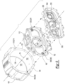
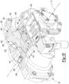
- the axle assembly 10 includes a housing assembly 20, an electric motor module 26, and a transmission module 28, and may include a differential assembly 22, at least one axle shaft 24, and a drive pinion 30.
- the axle assembly 10 includes a first lubricant passage 32 and may include a second lubricant passage 34, a shift mechanism 36, or combinations thereof.
- the housing assembly 20 may receive various components of the axle assembly 10.
- the housing assembly 20 may facilitate mounting of the axle assembly 10 to the vehicle.
- the housing assembly 20 may include an axle housing 40 and a differential carrier 42.
- the axle housing 40 may receive and may support the axle shafts 24.
- the axle housing 40 may include a center portion 50 and at least one arm portion 52.
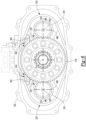
- the center portion 50 may be disposed proximate the center of the axle housing 40. As is best shown in Figure 2 , the center portion 50 may define a cavity 54 that at least partially receives the differential assembly 22. A lower region of the center portion 50 may at least partially define a sump portion 56 that contains or collects lubricant 58. Lubricant 58 in the sump portion 56 may be splashed by a ring gear 82 of the differential assembly 22 and distributed to lubricate various components that may or may not be received in the housing assembly 20.
- splashed lubricant 58 may lubricate components that are received in the cavity 54 like the differential assembly 22, bearing assemblies that rotatably support the differential assembly 22, a drive pinion 30, and so on, while some splashed lubricant 58 may be routed out of the cavity 54 via the first lubricant passage 32, which is best shown in Figure 12 , to lubricate components located outside of the housing assembly 20, such as components associated with the transmission module 28, the shift mechanism 36, or both as will be discussed in more detail below.
- one or more arm portions 52 may extend from the center portion 50.
- two arm portions 52 may extend in opposite directions from the center portion 50 and away from the differential assembly 22.
- the arm portions 52 may have substantially similar configurations.
- the arm portions 52 may each have a hollow configuration or tubular configuration that may extend around and may receive a corresponding axle shaft 24 and may help separate or isolate the axle shaft 24 or a portion thereof from the surrounding environment.
- An arm portion 52 or a portion thereof may or may not be integrally formed with the center portion 50. It is also contemplated that the arm portions 52 may be omitted.
- the differential carrier 42 may be mounted to the center portion 50 of the axle housing 40.
- the differential carrier 42 may support the differential assembly 22 and may facilitate mounting of the electric motor module 26.
- the differential carrier 42 may include one or more bearing supports that may support a bearing like a roller bearing assembly that may rotatably support the differential assembly 22.
- the differential carrier 42 may include a mounting flange 60 and/or a bearing support wall 62.
- the mounting flange 60 may facilitate mounting of the electric motor module 26.
- the mounting flange 60 may be configured as a ring that may extend outward and away from an axis 70 and may extend around the axis 70.
- the mounting flange 60 may include a set of fastener holes that may be configured to receive fasteners, such as a bolt or stud, that may secure the electric motor module 26 to the mounting flange 60.
- the bearing support wall 62 may support bearings that may rotatably support other components of the axle assembly 10.
- the bearing support wall 62 may support a bearing that may rotatably support the drive pinion 30, a bearing that may rotatably support a rotor of the electric motor module 26, or both.
- the bearing support wall 62 may extend in an axial direction away from the axle housing 40 and may extend around the axis 70.
- the bearing support wall 62 may define a hole that may extend along or around the axis 70 and receive the drive pinion 30 and the bearings that rotatably support the drive pinion 30.
- the bearing support wall 62 may be integrally formed with the differential carrier 42 or may be a separate component that is secured or fastened to the differential carrier 42.
- the differential assembly 22 may be at least partially received in the center portion 50 of the housing assembly 20.
- the differential assembly 22 may be rotatable about a differential axis 80 and may transmit torque to the axle shafts 24 and wheels.
- the differential assembly 22 may be operatively connected to the axle shafts 24 and may permit the axle shafts 24 to rotate at different rotational speeds in a manner known by those skilled in the art.
- the differential assembly 22 may have a ring gear 82 that may have teeth that mate or mesh with the teeth of a gear portion of the drive pinion 30. Accordingly, the differential assembly 22 may receive torque from the drive pinion 30 via the ring gear 82 and transmit torque to the axle shafts 24.
- the drive pinion 30 may operatively connect the transmission module 28 to the differential assembly 22. As such, the drive pinion 30 may transmit torque between the differential assembly 22 and the transmission module 28. In at least one configuration, the drive pinion 30 may be rotatable about the axis 70 and may be rotatably supported inside another component, such as the bearing support wall 62.
- the axle shafts 24 may transmit torque from the differential assembly 22 to corresponding wheel hubs and wheels.
- Two axle shafts 24 may be provided such that each axle shaft 24 extends through a different arm portion 52 of axle housing 40.
- the axle shafts 24 may extend along and may be rotatable about an axis, such as the differential axis 80.
- Each axle shaft 24 may have a first end and a second end. The first end may be operatively connected to the differential assembly 22. The second end may be disposed opposite the first end and may be operatively connected to a wheel.
- gear reduction may be provided between an axle shaft 24 and a wheel.
- the electric motor module 26 which may also be referred to as an electric motor, may be mounted to the differential carrier 42 and may be operatively connectable to the differential assembly 22.
- the electric motor module 26 may provide torque to the differential assembly 22 via the transmission module 28 and the drive pinion 30 as will be discussed in more detail below.
- the electric motor module 26 may be primarily disposed outside the differential carrier 42.
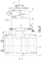
- the electric motor module 26 may be axially positioned between the axle housing 40 and the transmission module 28.
- the electric motor module 26 may include a motor housing 100, a coolant jacket 102, a stator 104, a rotor 106, at least one rotor bearing assembly 108, and a motor cover 110.
- the motor housing 100 may extend between the differential carrier 42 and the motor cover 110.
- the motor housing 100 may be mounted to the differential carrier 42 and the motor cover 110.
- the motor housing 100 may extend from the mounting flange 60 of the differential carrier 42 to the motor cover 110.
- the motor housing 100 may extend around the axis 70 and may define a motor housing cavity 120.
- the motor housing cavity 120 may be disposed inside the motor housing 100 and may have a generally cylindrical configuration.
- the bearing support wall 62 of the differential carrier 42 may be located inside the motor housing cavity 120.
- the motor housing 100 may extend continuously around and may be spaced apart from the bearing support wall 62.
- the motor housing 100 may have an exterior side 122, an interior side 124, a first end surface 126, and a second end surface 128.
- the exterior side 122 may face away from the axis 70 and may define an exterior or outside surface of the motor housing 100.
- the interior side 124 may be disposed opposite the exterior side 122 and may face toward the axis 70.
- the interior side 124 may be disposed at a substantially constant radial distance from the axis 70 in one or more configurations.
- the first end surface 126 may extend between the exterior side 122 and the interior side 124.
- the first end surface 126 may be disposed at an end of the motor housing 100 that may face toward the differential carrier 42.
- the first end surface 126 may be disposed adjacent to the mounting flange 60 of the differential carrier 42 and may engage or contact the mounting flange 60.
- the second end surface 128 may be disposed opposite the first end surface 126. As such, the second end surface 128 may be disposed at an end of the motor housing 100 that may face toward the motor cover 110 and may engage or contact the motor cover 110.
- the coolant jacket 102 may help cool or remove heat from the stator 104.
- the coolant jacket 102 may be received in the motor housing cavity 120 of the motor housing 100 and may engage the interior side 124 of the motor housing 100.
- the coolant jacket 102 may extend axially (e.g., in a direction along the axis 70) between the differential carrier 42 and the motor cover 110.
- the coolant jacket 102 may extend axially from the differential carrier 42 to the motor cover 110.
- the coolant jacket 102 may extend around the axis 70 and around the stator 104.
- the stator 104 may be at least partially received in and may be encircled by the coolant jacket 102.
- the coolant jacket 102 may extend in a radial direction from the stator 104 to the interior side 124 of the motor housing 100.
- the coolant jacket 102 may include a plurality of channels through which coolant may flow.
- the stator 104 may be received in the motor housing cavity 120.
- the stator 104 may be fixedly positioned with respect to the coolant jacket 102.
- the stator 104 may extend around the axis 70 and may include stator windings that may be received inside and may be fixedly positioned with respect to the coolant jacket 102.
- the rotor 106 may extend around and may be rotatable about the axis 70. In addition, the rotor 106 may extend around and may be supported by the bearing support wall 62. The rotor 106 may be received inside the stator 104, the coolant jacket 102, and the motor housing cavity 120 of the motor housing 100. The rotor 106 may be rotatable about the axis 70 with respect to the differential carrier 42 and the stator 104. In addition, the rotor 106 may be spaced apart from the stator 104 but may be disposed in close proximity to the stator 104. The rotor 106 may include magnets or ferromagnetic material that may facilitate the generation of electrical current or may be induction-based.
- One or more rotor bearing assemblies 108 may rotatably support the rotor 106.
- a rotor bearing assembly 108 may extend around and receive the bearing support wall 62 of the differential carrier 42 and may be received inside of the rotor 106.
- the rotor 106 may be operatively connected to the drive pinion 30.
- a coupling such as a rotor output flange 150 may operatively connect the rotor 106 to the transmission module 28, which in turn may be operatively connectable to the drive pinion 30.
- the motor cover 110 may be mounted to the motor housing 100 and may be disposed opposite the axle housing 40 and the differential carrier 42.
- the motor cover 110 may be mounted to the second end surface 128 of the motor housing 100.
- the motor cover 110 may be spaced apart from and may not engage the differential carrier 42.
- the motor cover 110 may be provided in various configurations. In at least one configuration, the motor cover 110 may include a first side 160 and a second side 162. The first side 160 may face toward and may engage the motor housing 100. The second side 162 may be disposed opposite the first side 160. The second side 162 may face away from the motor housing 100.
- the motor cover 110 may also include a motor cover opening 164 through which the drive pinion 30 may extend.
- the transmission module 28 may transmit torque between the electric motor module 26 and the differential assembly 22.
- the transmission module 28 may be operatively connectable to the electric motor module 26 and the differential assembly 22.
- the transmission module 28 includes a first transmission housing 200, a second transmission housing 202, and a transmission 204.
- the first transmission housing 200 and the second transmission housing 202 cooperate to define a transmission housing cavity 206 that receives the transmission 204.
- the first transmission housing 200 is mounted to the electric motor module 26.
- the first transmission housing 200 may be mounted to the second side 162 of the motor cover 110.
- the motor cover 110 may separate the first transmission housing 200 from the motor housing 100.
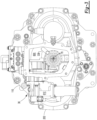
- the first transmission housing 200 may define a center hole 210, an outlet 502 of the first lubricant passage 32, and an inlet 550 of the second lubricant passage 34.
- the first transmission housing 200 may include first pocket 220, a first connection passage 222, a first outlet passage 224, a first channel 226, a second pocket 230, a second connection passage 232, a second outlet passage 234, a second channel 236, a deflector 238, or combinations thereof. It is noted that the arrowed lines in Figure 7 represent the flow of lubricant 58 that may be associated with these features.
- the center hole 210 may be a through hole that may extend around the axis 70 or along the axis 70. In at least one configuration, the center hole 210 may receive the drive pinion 30.
- the first pocket 220 may be configured as a recess or indentation in the first transmission housing 200 that may extend toward the motor cover 110 and away from the second transmission housing 202. As is best shown in Figure 7 , the first pocket 220 may receive a bearing assembly 240 that may rotatably support a first countershaft of the transmission 204.
- the first pocket 220 may have a generally circular or cylindrical configuration and may be spaced apart from the center hole 210. As is best shown in Figure 6 , the first pocket 220 or a portion thereof may be positioned below the outlet 502. In addition, the first pocket 220 may be laterally positioned closer to the center hole 210 than the outlet 502 is positioned to the center hole 210.
- the first connection passage 222 may extend from the outlet 502 of the first lubricant passage 32 to the first pocket 220. As such, the first connection passage 222 may route lubricant from the outlet 502 to the first pocket 220 and to the bearing assembly 240 that is received in the first pocket 220.
- the first connection passage 222 may be configured as a recess or indentation in the first transmission housing 200.
- the first connection passage 222 may extend downward toward the first pocket 220 to facilitate the flow of lubricant 58 under the force of gravity from the outlet 502 to the first pocket 220.
- the first connection passage 222 may be linear in one or more embodiments.
- the first outlet passage 224 may extend from the first pocket 220 in a direction that may extend away from the outlet 502, the first connection passage 222, or both.
- the first outlet passage 224 may be configured as a recess or indentation in the first transmission housing 200.
- the first outlet passage 224 may extend downward from the first pocket 220 to facilitate the flow of lubricant under the force of gravity from the first pocket 220 into the transmission housing cavity 206.
- the first connection passage 222 and the first outlet passage 224 may extend from opposite sides of the first pocket 220.
- the first channel 226 may route some lubricant 58 that exits the outlet 502 partially around the first pocket 220.
- the first channel 226 may be configured as a recess or indentation in the first transmission housing 200 that may extend toward the motor cover 110 and away from the second transmission housing 202.
- the first channel 226 may be spaced apart from the first pocket 220 and may extend partially around the first pocket 220.
- the first channel 226 may extend from the outlet 502 of the first lubricant passage 32 to a first channel end 250.
- the first channel end 250 may be disposed below the first pocket 220 or closer to the bottom of the first transmission housing 200 than the first pocket 220.
- the first channel end 250 may be disposed underneath the axis 70, the center hole 210, or combinations thereof.
- a first baffle 260 may deflect lubricant 58 that exits the outlet 502 of the first lubricant passage 32 into the first channel 226.
- the first baffle 260 may have any suitable configuration.
- the first baffle 260 may be configured as a generally flat plate that may extend over the outlet 502 and over a portion of the first channel 226.
- the first baffle 260 may be fixedly disposed on the first transmission housing 200.
- the first baffle 260 or a portion thereof may be received inside the first channel 226 and may be fastened to the first transmission housing 200 with one or more fasteners such as screws.
- the first baffle 260 may not cover the first channel end 250, thereby allowing lubricant 58 to exit the first channel 226 at the first channel end 250 and enter the transmission housing cavity 206.
- the second pocket 230 may be configured as a recess or indentation in the first transmission housing 200 that may extend toward the motor cover 110 and away from the second transmission housing 202.
- the second pocket 230 may receive a bearing assembly 240 that may rotatably support a second countershaft of the transmission 204.
- the second pocket 230 may have a generally circular or cylindrical configuration and may be spaced apart from the center hole 210.
- the center hole 210 may be positioned between the first pocket 220 and the second pocket 230.
- the second pocket 230 or a portion thereof may be positioned above the inlet 550 of the second lubricant passage 34.
- the second pocket 230 may be laterally positioned closer to the center hole 210 than the inlet 550 is positioned to the center hole 210.
- the second connection passage 232 may extend from the second channel 236 to the second pocket 230. As such, the second connection passage 232 may route lubricant 58 from the second channel 236 to the second pocket 230 and the bearing assembly 240 that is received in the second pocket 230.
- the second connection passage 232 may be configured as a recess or indentation in the first transmission housing 200.
- the second connection passage 232 may extend downward from the second channel 236 toward the second pocket 230 to facilitate the flow of lubricant 58 under the force of gravity from the second channel 236 to the second pocket 230.
- the second connection passage 232 may be linear in one or more embodiments.
- the second outlet passage 234 may extend from the second pocket 230 in a direction that may extend away from the second connection passage 232.
- the second outlet passage 234 may be configured as a recess or indentation in the first transmission housing 200.
- the second outlet passage 234 may extend downward from the second pocket 230 to facilitate the flow of lubricant 58 under the force of gravity from the second pocket 230 into the transmission housing cavity 206.
- the second connection passage 232 and the second outlet passage 234 may extend from opposite sides of the second pocket 230.
- the second channel 236 may route some lubricant 58 around the second pocket 230 to the inlet 550 of the second lubricant passage 34.
- the second channel 236 may be configured as a recess or indentation in the first transmission housing 200 that may extend toward the motor cover 110 and away from the second transmission housing 202.
- the second channel 236 may be spaced apart from the second pocket 230 and may extend partially around the second pocket 230.
- the second channel 236 may extend from an enlarged end portion 270 of the second channel 236 to the inlet 550 of the second lubricant passage 34.
- the enlarged end portion 270 may be located above the axis 70 and the center hole 210.
- a second baffle 280 may deflect or direct lubricant 58 from the second channel 236 into the inlet 550.
- the second baffle 280 may have any suitable configuration.
- a portion of the second baffle 280 may be configured as a generally flat plate that may extend over the inlet 550 and a portion of the second channel 236.
- the second baffle 280 may be fixedly disposed on the first transmission housing 200.
- a portion of the second baffle 280 may be received inside the second channel 236 and may be fastened to the first transmission housing 200 with one or more fasteners such as screws.
- the second baffle 280 may include a scoop 282.
- the scoop 282 may protrude from the first transmission housing 200 into the transmission housing cavity 206 and may be configured to capture lubricant 58, such as lubricant that may be splashed by the transmission 204 as the transmission 204 rotates in the transmission housing cavity 206.
- the scoop 282 may be disposed above the axis 70 and may be disposed above the center hole 210.
- the scoop 282 may be generally aligned with the enlarged end portion 270 of the second channel 236 and may be open in an upward-facing direction that may face away from the axis 70 so that the scoop 282 may capture or collect splashed lubricant 58 and cooperate with the first transmission housing 200 to direct or route the lubricant 58 into the second channel 236.
- the scoop 282 may engage the deflector 238, may be fastened to the deflector 238, or both.
- the deflector 238 may be disposed above the axis 70 and may extend from the first transmission housing 200 toward the second transmission housing 202. As such, the deflector 238 may extend into the transmission housing cavity 206. The deflector 238 may direct lubricant 58 into the enlarged end portion 270 and/or the scoop 282. For instance, the deflector 238 may extend from a top interior side of the first transmission housing 200 in a downward direction toward the axis 70 and may be at least partially defined by opposing first and second surfaces 290, 292. The first and second surfaces 290, 292 may extend along an arc and may direct lubricant 58 into the enlarged end portion 270 and/or the scoop 282.
- the deflector 238 and its first and second surfaces 290, 292 may help disrupt or redirect lubricant 58 so that at least some lubricant 58 does not circulate in a loop along the interior surface 294 of the first transmission housing 200 when the transmission 204 rotates.
- countershaft gears of the transmission 204 may rotate in a common rotational direction. This rotation may cause lubricant to circulate along the interior surface 294 of the first transmission housing 200 and reduce the amount of lubricant 58 that enters the inlet 550 of the second lubricant passage 34.
- the deflector 238 may disrupt lubricant circulation along the interior surface 294 so that more lubricant 58 may enter the second channel 236 and exit the transmission housing cavity 206 via that inlet 550 and the second lubricant passage 34, which may help reduce churning losses that may occur when excess lubricant 58 is in the transmission housing cavity 206 and may help improve operating efficiency of the axle assembly and may reduce energy consumption or power losses.
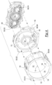
- the second transmission housing 202 is shown.
- Figures 8 and 9 face along the axis 70 away from the first transmission housing 200 and the electric motor module 26 and thus are in the opposite direction along the axis 70 from the perspective shown in Figure 6 and 7 .
- the second transmission housing 202 is mounted to the first transmission housing 200.
- the first transmission housing 200 may be mounted to and may engage or contact a side of the first transmission housing 200 that may face away from the motor cover 110.
- the first transmission housing 200 may separate the second transmission housing 202 from the motor cover 110.
- the second transmission housing 202 may define a center hole 310 and a lubricant outlet hole 312.
- the second transmission housing 202 may also include first pocket 320, a first inlet slot 322, a first outlet slot 324, a second pocket 330, a second inlet slot 332, a second outlet slot 334, a ledge 336, or combinations thereof.
- a lubricant catcher 340 may be provided with the second transmission housing 202.
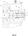
- the center hole 310 may be a through hole that may extend around the axis 70 or along the axis 70. In at least one configuration, the center hole 310 may receive the drive pinion 30 or an extension of the drive pinion 30 like the connecting member 420, which is best shown in Figure 14 .
- the lubricant outlet hole 312 may be configured as a through hole that may extend through a wall of the second transmission housing 202.
- the lubricant outlet hole 312 may direct lubricant 58 that is captured by the lubricant catcher 340 into a shift mechanism housing cavity 600, which is best shown in Figure 14 .
- the lubricant outlet hole 312 may be fluidly connected to a pipe or tube 338 that may route lubricant 58 from the lubricant outlet hole 312 to a desired location in the shift mechanism housing cavity 600.
- the first pocket 320 may be configured as a recess or indentation in the second transmission housing 202 that may extend away from the first transmission housing 200. As is best shown in Figure 8 , the first pocket 320 may receive a bearing assembly 240 that may rotatably support a first countershaft of the transmission 204. As is best shown in Figure 9 , the first pocket 320 may have a generally circular or cylindrical configuration and may be spaced apart from the center hole 310. The first pocket 320 or a portion thereof may be positioned below the lubricant outlet hole 312. In addition, the first pocket 320 may be aligned with and may be coaxially disposed with the first pocket 220 of the first transmission housing 200.
- the first inlet slot 322 may route lubricant 58 to the first pocket 320 and the bearing assembly 240 that it receives.
- the first inlet slot 322 may be configured as a recess or indentation in the second transmission housing 202 that may extend away from the first transmission housing 200.
- the first inlet slot 322 that may extend from an outside circumference of the first pocket 320. In at least one configuration, the first inlet slot 322 may extend between the ledge 336 and the first pocket 320.
- the first inlet slot 322 may extend downward toward the first pocket 320 to facilitate the flow of lubricant 58 under the force of gravity from the ledge 336 to the first pocket 320.
- the first inlet slot 322 may be linear in one or more embodiments.
- the first outlet slot 324 may allow lubricant 58 to exit the first pocket 320 and the bearing assembly 240 that it receives.
- the first outlet slot 324 may be configured as a recess or indentation in the second transmission housing 202.
- the first outlet slot 324 may extend from or protrude outwardly from an outside circumference of the first pocket 320. In at least one configuration, the first outlet slot 324 may extend from the first pocket 320 in a direction that may extend away from the center hole 310.
- the second inlet slot 332 may route lubricant 58 to the second pocket 330 and the bearing assembly 240 that it receives.
- the second inlet slot 332 may be configured as a recess or indentation in the second transmission housing 202 that may extend away from the first transmission housing 200.
- the second inlet slot 332 that may extend from an outside circumference of the second pocket 330. In at least one configuration, the second inlet slot 332 may extend between the ledge 336 and the second pocket 330.
- the second inlet slot 332 may extend downward toward the second pocket 330 to facilitate the flow of lubricant 58 under the force of gravity from the ledge 336 to the second pocket 330.
- the second inlet slot 332 may be linear in one or more embodiments.
- the second outlet slot 334 may be spaced apart from the second inlet slot 332 and may be positioned closer to the bottom of the second transmission housing 202 than the second inlet slot 332 to facilitate the flow of lubricant 58 under the force of gravity from the second pocket 330 into the transmission housing cavity 206.
- the ledge 336 may extend away from the first transmission housing 200.
- the ledge 336 may include one or more generally horizontal surfaces that may extend from the center hole 310 or a ring that may extend around the center hole 310.
- the ledge 336 may be disposed underneath the lubricant catcher 340.
- the lubricant catcher 340 may be configured to capture lubricant 58 that may be splashed by the transmission 204 as the transmission 204 rotates in the transmission housing cavity 206.
- the lubricant catcher 340 extends from the second transmission housing 202 toward the first transmission housing 200 such that the lubricant catcher 340 is spaced apart from the first transmission housing 200. As such, the lubricant catcher 340 may protrude from the second transmission housing 202 into the transmission housing cavity 206.
- the lubricant catcher 340 may be disposed above the axis 70 and may be disposed above the center hole 310 of the second transmission housing 202.
- the lubricant catcher 340 may straddle or extend over at least one member of the set of drive pinion gears 400 of the transmission 204.
- the lubricant catcher 340 may straddle or extend over at least a portion of the fourth gear 416 of the set of drive pinion gears 400.
- the lubricant catcher 340 or a portion thereof may extend over a member of the first countershaft gear set 402 of the transmission 204, a member of the second countershaft gear set 404 of the transmission 204, or combinations thereof.
- the lubricant catcher 340 is shown extending over a fourth countershaft gear 466 of the first countershaft gear set 402 and a fourth countershaft gear 466' of the second countershaft gear set 404.
- the lubricant catcher 340 may be open in an upward-facing direction that may face away from the axis 70 so that the lubricant catcher 340 may cooperate with the second transmission housing 202 to capture or collect lubricant 58 and direct or route the lubricant 58 into the lubricant outlet hole 312.
- the lubricant catcher 340 may be a separate component from the second transmission housing 202 that may be attached to the second transmission housing 202 in any suitable manner. For instance, the lubricant catcher 340 may be received in one or more slots 350, which are best shown in Figure 9 , that may be provided with the second transmission housing 202.
- the lubricant catcher 340 may be attached to the second transmission housing 202 with one or more fasteners.
- the fasteners may or may not be integrally formed with the lubricant catcher 340.
- the lubricant catcher 340 may at least partially define a center trough 360, a first end trough 362, a second end trough 364, or combinations thereof.
- the center trough 360 may extend laterally along the second transmission housing 202.
- the second transmission housing 202 and the lubricant catcher 340 may cooperate to define the center trough 360.
- Lubricant 58 that is captured by the lubricant catcher 340 may be routed to the lubricant outlet hole 312.
- the first end trough 362 may extend from the center trough 360 toward the first transmission housing 200 to help capture more lubricant 58 than may be captured by the center trough 360. Lubricant 58 that is captured by the first end trough 362 may be routed to the center trough 360.
- the first end trough 362 may be spaced apart from the top of the second transmission housing 202 and may be disposed above one or more gears of the transmission 204. For instance, the first end trough 362 may be disposed above a member of the set of drive pinion gears 400, a member of the first countershaft gear set 402, or both.
- the second transmission housing 202 and the lubricant catcher 340 may cooperate to define the first end trough 362.
- the second end trough 364 may be spaced apart from the first end trough 362.
- the second end trough 364 may extend from the center trough 360 toward the first transmission housing 200 to help capture more lubricant 58 than may be captured by the center trough 360.
- the second end trough 364 may be disposed at an opposite end of the center trough 360 from the first end trough 362.
- member of the set of drive pinion gears 400 like the fourth gear 416 may be received between the first end trough 362 and the second end trough 364.
- Lubricant 58 that is captured by the second end trough 364 may be routed to the center trough 360.
- the second end trough 364 may be spaced apart from the top of the second transmission housing 202 and may be disposed above one or more gears of the transmission 204. For instance, the second end trough 364 may be disposed above a member of the set of drive pinion gears 400, a member of the second countershaft gear set 404, or both. In at least one configuration, the second transmission housing 202 and the lubricant catcher 340 may cooperate to define the second end trough 364.
- the transmission 204 may be operatively connected to the electric motor.
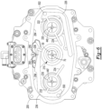
- the transmission 204 may be configured as a countershaft transmission that may include a set of drive pinion gears 400, a first countershaft gear set 402, and a second countershaft gear set 404.
- the set of drive pinion gears 400 may be received in the transmission housing cavity 206 and may be arranged along the axis 70 between the first transmission housing 200 and the second transmission housing 202.
- the set of drive pinion gears 400 may include a plurality of gears, some of which may be selectively coupled to the drive pinion 30.
- the set of drive pinion gears 400 includes a first gear 410, a second gear 412, a third gear 414, and a fourth gear 416; however, it is to be understood that a greater or lesser number of gears may be provided.
- the first gear 410 may extend around the axis 70 and may be disposed proximate the first transmission housing 200. In at least one configuration, the first gear 410 may have a through hole that may receive the drive pinion 30, an extension of the drive pinion 30 like the connecting member 420, or both.
- the first gear 410 may have a plurality of teeth that may be arranged around and may extend away from the axis 70. The teeth of the first gear 410 may contact and may mate or mesh with teeth of a first countershaft gear that may be provided with the first countershaft gear set 402 and the second countershaft gear set 404 as will be discussed in more detail below.
- the first gear 410 may be operatively connected to the rotor 106 of the electric motor module 26 such that the rotor 106 and the first gear 410 are rotatable together about the axis 70.
- the first gear 410 may be fixedly positioned with respect to the rotor 106 or fixedly coupled to the rotor 106 such that the first gear 410 is not rotatable about the axis 70 with respect to the rotor 106.
- the first gear 410 may be fixedly mounted to or integrally formed with the rotor output flange 150.
- the first gear 410 may be continuously decoupled from the drive pinion 30 and may be rotatable with respect to the drive pinion 30.
- a clutch may not connect the first gear 410 to the drive pinion 30 or the connecting member 420.
- the connecting member 420 if provided, may be received inside the first gear 410 and may be spaced apart from the first gear 410.
- the first gear 410 may be axially positioned along the axis 70 between the second gear 412 and the electric motor module 26.
- the second gear 412 may extend around the axis 70.
- the second gear 412 may have a through hole that may receive the drive pinion 30, the connecting member 420, or both.
- the second gear 412 may have a plurality of teeth that may be arranged around and may extend away from the axis 70.
- the teeth of the second gear 412 may contact and may mate or mesh with teeth of a second countershaft gear that may be provided with the first countershaft gear set 402 and the second countershaft gear set 404 as will be discussed in more detail below.
- the second gear 412 may have a different diameter than the first gear 410.
- the second gear 412 may have a larger diameter than the first gear 410.
- the second gear 412 may be axially positioned along the axis 70 between the first gear 410 and the third gear 414.
- the connecting member 420 may be received inside the second gear 412 and may be spaced apart from the second gear 412 in one or more configurations.
- the third gear 414 may extend around the axis 70.
- the third gear 414 may have a through hole that may receive the drive pinion 30, the connecting member 420, or both.
- the third gear 414 may have a plurality of teeth that may be arranged around and may extend away from the axis 70.
- the teeth of the third gear 414 may contact and may mate or mesh with teeth of a third countershaft gear that may be provided with the first countershaft gear set 402 and the second countershaft gear set 404 as will be discussed in more detail below.
- the third gear 414 may have a different diameter than the first gear 410 and the second gear 412.
- the third gear 414 may have a larger diameter than the first gear 410 and the second gear 412.
- the third gear 414 be axially positioned along the axis 70 between the second gear 412 and the fourth gear 416.
- the connecting member 420 may be received inside the third gear 414 and may be spaced apart from the third gear 414 in one or more configurations.
- the fourth gear 416 may extend around the axis 70.
- the fourth gear 416 may have a through hole that may receive the drive pinion 30, a connecting member 420, or both.
- the fourth gear 416 may have a plurality of teeth that may be arranged around and may extend away from the axis 70.
- the teeth of the fourth gear 416 may contact and may mate or mesh with teeth of a fourth countershaft gear that may be provided with the first countershaft gear set 402 and the second countershaft gear set 404 as will be discussed in more detail below.
- the fourth gear 416 may have a different diameter than the first gear 410, the second gear 412, and the third gear 414, such as a larger diameter.
- the fourth gear 416 be axially positioned along the axis 70 further from the electric motor module 26 than the first gear 410, the second gear 412, and the third gear 414.
- the fourth gear 416 may be axially positioned proximate or adjacent to the second transmission housing 202.
- the connecting member 420 may be received inside the fourth gear 416 and may be spaced apart from the fourth gear 416 in one or more configurations.
- the first countershaft gear set 402 may be received in the transmission housing cavity 206 and may be in meshing engagement with the set of drive pinion gears 400.
- the first countershaft gear set 402 may be rotatable about a first countershaft axis 440.
- the first countershaft axis 440 may be disposed parallel or substantially parallel to the axis 70 in one or more embodiments.
- the first countershaft gear set 402 may include a first countershaft 450 and a plurality of gears.
- the plurality of gears of the first countershaft gear set 402 include a first countershaft gear 460, a second countershaft gear 462, a third countershaft gear 464, and a fourth countershaft gear 466; however, it is contemplated that a greater number of countershaft gears or a lesser number of countershaft gears may be provided.
- the teeth of the first countershaft gear 460 may contact and may mate or mesh with the teeth of the first gear 410.
- the first countershaft gear 460 may be axially positioned along the first countershaft axis 440 between the second countershaft gear 462 of the first countershaft gear set 402 and the first transmission housing 200.
- the portion 510 of the first lubricant passage 32 that is defined by the motor housing 100 may be disposed between and may be spaced apart from the exterior side 122 and the interior side 124 of the motor housing 100. As such, the portion 510 may be radially positioned further from the axis 70 than the stator 104, the coolant jacket 102, and the interior side 124.
- the portion 510 may extend between an inlet port 512 and an outlet port 514.
- the inlet port 512 may face toward the differential carrier 42 and may be fluidly connected to the inlet 500.
- the outlet port 514 may be disposed opposite the inlet port 512 and may be disposed adjacent to the motor cover 110.
- the portion 520 of the first lubricant passage 32 that is defined by the motor cover 110 may be disposed between and may be spaced apart from the exterior side and the interior side of the motor cover 110. As such, the portion 520 may be radially positioned further from the axis 70 than the motor cover opening 164.
- the portion 520 may extend between an inlet port 522 and an outlet port 524.
- the inlet port 522 may face toward the motor housing 100 and may be fluidly connected to the outlet port 514.
- the outlet port 524 may be disposed opposite the inlet port 522 and may be disposed adjacent to the first transmission housing 200.
- the portion 530 of the first lubricant passage 32 that is defined by the first transmission housing 200 may extend between and inlet port 532 and the outlet 502.
- the inlet port 532 may face toward the motor cover 110 and may be fluidly connected to the of the outlet port 524.
- the outlet 502 may be disposed opposite the inlet port 532.
- the second lubricant passage 34 may return lubricant to the sump portion 56 of the housing assembly 20.
- the second lubricant passage 34 may route lubricant 58 from the transmission housing cavity 206 to the housing assembly 20 and may allow a common type of lubricant 58 or a common sump portion 56 to be provided with the axle assembly 10.
- the second lubricant passage 34 may be spaced apart from the first lubricant passage 32. In the configuration shown, the second lubricant passage 34 is disposed on an opposite side of the axle assembly 10 from the first lubricant passage 32.
- the second lubricant passage 34 may be at least partially defined by through holes in the first transmission housing 200, the motor cover 110, the motor housing 100, and the differential carrier 42 that may be fluidly connected to each other. As such, the second lubricant passage 34 may extend through the first transmission housing 200, the motor cover 110, and the motor housing 100. The second lubricant passage 34 may be at least partially defined in the exterior walls of the first transmission housing 200, the motor cover 110, and the motor housing 100.
- Such a configuration may allow lubricant 58 to be routed away from the axis 70 and around the stator 104 and rotor 106 to transport lubricant 58 from the transmission housing cavity 206 to the housing assembly 20 rather than routing lubricant 58 through the motor housing cavity 120 of the motor housing 100, through the motor cover opening 164 of the motor cover 110, or both.
- the second lubricant passage 34 may be at least partially disposed below the first lubricant passage 32.
- the second lubricant passage 34 or a portion thereof may be disposed below the axis 70.
- the second lubricant passage 34 may have at least one inlet 550 and at least one outlet 552.
- the inlet 550 may be defined by the first transmission housing 200.
- the inlet 500 may receive lubricant 58 that is splashed by the transmission 204, such as when the transmission 204 rotates as previously discussed.
- the inlet 550 may be disposed above the outlet 552. As such, the second lubricant passage 34 or a portion thereof may slope downward from the inlet 550 toward or to the outlet 552.
- the outlet 552 may be provided with the differential carrier 42.
- the portion 560 of the second lubricant passage 34 that is defined by the first transmission housing 200 may extend between and inlet 550 and an outlet port 574.
- the inlet 550 may face toward and may be fluidly connected to the transmission housing cavity 206.
- the outlet port 574 may be disposed opposite the inlet 550.
- the portion 580 of the second lubricant passage 34 that is defined by the motor cover 110 may be disposed between and may be spaced apart from the exterior side and the interior side of the motor cover 110. As such, the portion 580 may be radially positioned further from the axis 70 than the motor cover opening 164.
- the portion 580 may extend between an inlet port 582 and an outlet port 584.
- the inlet port 582 may face toward the first transmission housing 200 and may be fluidly connected to the of the outlet port 574.
- the outlet port 584 may be disposed opposite the inlet port 582 and may be disposed adjacent to the motor housing 100.
- the portion 590 of the second lubricant passage 34 that is defined by the motor housing 100 may be disposed between and may be spaced apart from the exterior side 122 and the interior side 124 of the motor housing 100. As such, the portion 590 may be radially positioned further from the axis 70 than the stator 104, the coolant jacket 102, and the interior side 124.
- the portion 590 may extend between an inlet port 592 and an outlet port 594.
- the inlet port 592 may face toward the motor cover 110 and may be fluidly connected to the outlet port 584.
- the outlet port 594 may be disposed opposite the inlet port 512 and may be disposed adjacent to the differential carrier 42 and may be fluidly connected to the outlet 552 of the second lubricant passage 34.
- the shift mechanism 36 may cooperate with the transmission module 28 to provide a desired gear reduction ratio to change the torque provided from the electric motor module 26 to the differential assembly 22, and hence to the axle shafts 24 of the axle assembly 10.
- the shift mechanism 36 may operatively connect a member of the set of drive pinion gears 400 to the drive pinion 30 such that the connected drive pinion gear is rotatable with the drive pinion 30. More specifically, the shift mechanism 36 may couple one member of the set of drive pinion gears 400 at a time to the drive pinion 30 to provide different drive gear ratios.
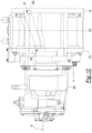
- the shift mechanism 36 may be received in or partially received in a shift mechanism housing cavity 600, which is best shown in Figures 3 and 14 .
- the shift mechanism housing cavity 600 may be partially defined by the second transmission housing 202 and may be disposed proximate an end of the axle assembly 10.
- the shift mechanism 36 may have any suitable configuration.
- the shift mechanism 36 may include one of more clutches of any suitable type.
- the shift mechanism 36 includes a shift collar 610 that may be moveable along the axis 70 to selectively connect a member of the set of drive pinion gears 400 to the drive pinion 30 so that a connected gear may rotate about the axis 70 with the drive pinion 30.
- An actuator 612 may actuate the shift mechanism 36.
- the actuator 612 may be of any suitable type, such as an electric, electromechanical, or mechanical actuator.
Landscapes
- Engineering & Computer Science (AREA)
- General Engineering & Computer Science (AREA)
- Mechanical Engineering (AREA)
- Chemical & Material Sciences (AREA)
- Combustion & Propulsion (AREA)
- Transportation (AREA)
- Power Engineering (AREA)
- General Details Of Gearings (AREA)
Claims (15)
- Achsanordnung (10), die Folgendes umfasst:eine Gehäuseanordnung (20), die eine Differentialanordnung (22) aufnimmt und die zumindest teilweise einen Hohlraum (54) definiert, der einen Sumpfabschnitt (56) aufweist, der Schmiermittel (58) aufnimmt;ein Elektromotormodul (26), das an der Gehäuseanordnung (20) montiert ist;ein Getriebemodul (28), das Folgendes beinhaltet:ein erstes Getriebegehäuse (200), das an dem Elektromotormodul (26) montiert ist und über einen ersten Schmiermitteldurchlass (32) mit der Gehäuseanordnung (20) strömungstechnisch verbunden ist; undein zweites Getriebegehäuse (202), das an dem ersten Getriebegehäuse (200) montiert ist, wobei das erste und das zweite Getriebegehäuse (200, 202) zusammenwirken, um einen Getriebegehäusehohlraum (206) zu definieren, der ein Getriebe (204) aufnimmt, und eine Schmiermittelauffangvorrichtung (340) in dem Getriebegehäusehohlraum (206) aufgenommen ist, wobei die Schmiermittelauffangvorrichtung (340) an dem zweiten Getriebegehäuse (202) montiert ist und sich von dem zweiten Getriebegehäuse (202) hin zu dem ersten Getriebegehäuse (200) erstreckt.
- Achsanordnung nach Anspruch 1, wobei das zweite Getriebegehäuse (202) ein mittleres Loch (310) definiert, das sich entlang einer Achse (70) erstreckt, wobei das Getriebe (204) einen Satz von Antriebsritzeln (400) beinhaltet, die entlang der Achse (70) zwischen dem ersten Getriebegehäuse (200) und dem zweiten Getriebegehäuse (202) angeordnet sind, und wobei sich zumindest ein Abschnitt der Schmiermittelauffangvorrichtung (340) über mindestens ein Element des Satzes von Antriebsritzeln (400) erstreckt.
- Achsanordnung nach Anspruch 2, wobei die Schmiermittelauffangvorrichtung (340) zumindest teilweise eine mittlere Wanne (360), die sich entlang des zweiten Getriebegehäuses (202) erstreckt, und eine erste Endwanne (362), die sich von der mittleren Wanne (360) hin zu dem ersten Getriebegehäuse (200) erstreckt, definiert, wobei die erste Endwanne (362) über einem Element des Satzes von Antriebsritzeln (400) angeordnet ist.
- Achsanordnung nach Anspruch 3, wobei die Schmiermittelauffangvorrichtung (340) zumindest teilweise eine zweite Endwanne (364) definiert, die sich von der mittleren Wanne (360) hin zu dem ersten Getriebegehäuse (200) erstreckt und die von der ersten Endwanne (362) beabstandet ist, wobei das Element des Satzes von Antriebsritzeln (400) zwischen der ersten Endwanne (362) und der zweiten Endwanne (364) aufgenommen ist.
- Achsanordnung nach Anspruch 4, wobei das zweite Getriebegehäuse (202) und die Schmiermittelauffangvorrichtung (340) zusammenwirken, um die mittlere Wanne (360) und/oder die erste Endwanne (362) und/oder die zweite Endwanne (364) zu definieren, und die Schmiermittelauffangvorrichtung (340) von dem ersten Getriebegehäuse (200) beabstandet ist.
- Achsanordnung nach Anspruch 4 oder Anspruch 5, wobei das Getriebe (204) einen ersten Vorgelegewellenradsatz (402), der um eine erste Vorgelegewellenachse (440) drehbar ist, und einen zweiten Vorgelegewellenradsatz (404), der um eine zweite Vorgelegewellenachse (440') drehbar ist, beinhaltet, und wobei sich die Schmiermittelauffangvorrichtung (340) über ein Element des ersten Vorgelegewellenradsatzes (402) und ein Element des zweiten Vorgelegewellenradsatzes (404) erstreckt.
- Achsanordnung nach Anspruch 1, wobei das zweite Getriebegehäuse (202) eine erste Tasche (320), die eine Lageranordnung (240) aufnimmt, die eine erste Vorgelegewelle (450) drehbar stützt, einen ersten Einlassschlitz (322), der von einem Außenumfang der ersten Tasche (320) vorsteht, und einen ersten Auslassschlitz (322), der von dem ersten Einlassschlitz (322) beabstandet ist und von dem Außenumfang der ersten Tasche (320) nach außen vorsteht, definiert, wobei der erste Einlassschlitz (322) einen Schmiermittelfluss zu der ersten Tasche (320) ermöglicht und der erste Auslassschlitz (324) einen Schmiermittelfluss aus der ersten Tasche (320) ermöglicht.
- Achsanordnung nach Anspruch 7, wobei das zweite Getriebegehäuse (202) einen Vorsprung (336) definiert, der unterhalb der Schmiermittelauffangvorrichtung (340) angeordnet ist, wobei sich der erste Einlassschlitz (322) von dem Vorsprung (322) erstreckt.
- Achsanordnung nach Anspruch 1, wobei das zweite Getriebegehäuse (202) ein Schmiermittelauslassloch (312) aufweist, das ein Durchgangsloch ist, das sich durch das zweite Getriebegehäuse (202) erstreckt, und wobei Schmiermittel (58), das von der Schmiermittelauffangvorrichtung (340) erfasst wird, zu dem Schmiermittelauslassloch (312) geleitet wird.
- Achsanordnung nach Anspruch 9, wobei das Schmiermittelauslassloch (312) Schmiermittel (58), das von der Schmiermittelauffangvorrichtung (340) erfasst wird, in einen Schaltmechanismusgehäusehohlraum (600) leitet.
- Achsanordnung nach einem der vorhergehenden Ansprüche, wobei die Schmiermittelauffangvorrichtung (340) dazu ausgelegt ist, Schmiermittel (58) zu erfassen, das durch das Getriebe (204) verspritzt wird, wenn das Getriebe (204) in dem Getriebegehäusehohlraum (206) gedreht wird.
- Achsanordnung nach Anspruch 1, wobei die Schmiermittelauffangvorrichtung (340) über einer Achse (70) und über einem mittleren Loch (310) des zweiten Getriebegehäuses (202) angeordnet ist.
- Achsanordnung nach Anspruch 12, wobei die Schmiermittelauffangvorrichtung (340) in einer nach oben zeigenden Richtung offen ist, die von der Achse (70) weg zeigt.
- Achsanordnung nach einem der vorhergehenden Ansprüche, wobei die Schmiermittelauffangvorrichtung (340) eine von dem zweiten Getriebegehäuse (202) separate Komponente ist.
- Achsanordnung nach einem der vorhergehenden Ansprüche, wobei die Schmiermittelauffangvorrichtung (340) in einem oder mehreren Schlitzen (350) des zweiten Getriebegehäuses (202) aufgenommen ist.
Applications Claiming Priority (2)
| Application Number | Priority Date | Filing Date | Title |
|---|---|---|---|
| US17/178,502 US11168783B1 (en) | 2021-02-18 | 2021-02-18 | Axle assembly having a transmission module |
| EP22157164.9A EP4056878B1 (de) | 2021-02-18 | 2022-02-17 | Achsanordnung mit einem getriebemodul |
Related Parent Applications (2)
| Application Number | Title | Priority Date | Filing Date |
|---|---|---|---|
| EP22157164.9A Division EP4056878B1 (de) | 2021-02-18 | 2022-02-17 | Achsanordnung mit einem getriebemodul |
| EP22157164.9A Division-Into EP4056878B1 (de) | 2021-02-18 | 2022-02-17 | Achsanordnung mit einem getriebemodul |
Publications (2)
| Publication Number | Publication Date |
|---|---|
| EP4155583A1 EP4155583A1 (de) | 2023-03-29 |
| EP4155583B1 true EP4155583B1 (de) | 2025-04-09 |
Family
ID=78467387
Family Applications (2)
| Application Number | Title | Priority Date | Filing Date |
|---|---|---|---|
| EP22157164.9A Active EP4056878B1 (de) | 2021-02-18 | 2022-02-17 | Achsanordnung mit einem getriebemodul |
| EP22206702.7A Active EP4155583B1 (de) | 2021-02-18 | 2022-02-17 | Achsanordnung mit einem getriebemodul |
Family Applications Before (1)
| Application Number | Title | Priority Date | Filing Date |
|---|---|---|---|
| EP22157164.9A Active EP4056878B1 (de) | 2021-02-18 | 2022-02-17 | Achsanordnung mit einem getriebemodul |
Country Status (3)
| Country | Link |
|---|---|
| US (1) | US11168783B1 (de) |
| EP (2) | EP4056878B1 (de) |
| CN (1) | CN114962601B (de) |
Families Citing this family (8)
| Publication number | Priority date | Publication date | Assignee | Title |
|---|---|---|---|---|
| JP2023044078A (ja) * | 2021-09-17 | 2023-03-30 | トヨタ自動車株式会社 | 動力伝達装置 |
| DE102022102854B4 (de) | 2022-02-08 | 2023-12-07 | Schaeffler Technologies AG & Co. KG | Elektrisch betreibbarer Achsantriebsstrang |
| CN114704614B (zh) * | 2022-03-25 | 2025-01-28 | 重庆长安汽车股份有限公司 | 一种变速器箱体的集成结构及汽车 |
| US12523290B2 (en) | 2022-05-17 | 2026-01-13 | Borg Warner Inc. | Electric vehicle transmission |
| US12403762B2 (en) | 2023-04-10 | 2025-09-02 | Arvinmeritor Technology, Llc | Axle assembly having a shift mechanism |
| US11859718B1 (en) | 2023-04-24 | 2024-01-02 | Arvinmeritor Technology, Llc | Axle assembly having a shift collar |
| US11953090B1 (en) | 2023-06-07 | 2024-04-09 | Arvinmeritor Technology, Llc | Shift control device and a method of controlling an axle assembly |
| US12043099B1 (en) | 2023-10-02 | 2024-07-23 | Arvinmeritor Technology, Llc | Axle assembly having a shift mechanism |
Family Cites Families (29)
| Publication number | Priority date | Publication date | Assignee | Title |
|---|---|---|---|---|
| US1981236A (en) | 1932-12-22 | 1934-11-20 | Charles H Logue | Variable speed power transmitting mechanism |
| US2602712A (en) * | 1947-09-23 | 1952-07-08 | Joseph R Broadbent | Lubricated shaft bearing |
| US3529698A (en) * | 1967-05-05 | 1970-09-22 | Gen Electric | Self-operating lubrication system for gear drive units |
| US6176146B1 (en) | 1998-11-12 | 2001-01-23 | Zf Meritor, Llc | Output shaft arrangement for manual transmission auxiliary boxes |
| US6853143B2 (en) * | 2002-01-09 | 2005-02-08 | Ebara Corporation | Electron beam system and method of manufacturing devices using the system |
| DE102005020606A1 (de) | 2005-05-03 | 2006-12-14 | Daimlerchrysler Ag | Getriebe mit im Direktgang abkoppelbarer Vorgelegewelle |
| DE102008000900A1 (de) * | 2008-04-01 | 2009-10-08 | Zf Friedrichshafen Ag | Planetengetriebe |
| JP4572956B2 (ja) | 2008-06-03 | 2010-11-04 | トヨタ自動車株式会社 | 車両の駆動装置 |
| WO2014045707A1 (ja) * | 2012-09-21 | 2014-03-27 | 日立オートモティブシステムズ株式会社 | 車両用駆動装置 |
| JP6278332B2 (ja) | 2013-04-22 | 2018-02-14 | スズキ株式会社 | 変速機の制御装置 |
| JP6613318B2 (ja) | 2015-05-04 | 2019-11-27 | ボルボトラックコーポレーション | デュアルクラッチトランスミッションの非活動ギアを切り離すための方法及び対応トランスミッション |
| KR101755833B1 (ko) | 2015-09-02 | 2017-07-10 | 현대자동차주식회사 | 차량용 변속기 |
| JP6596364B2 (ja) * | 2016-03-10 | 2019-10-23 | 本田技研工業株式会社 | モータ式動力装置 |
| US20180015816A1 (en) | 2016-07-12 | 2018-01-18 | GM Global Technology Operations LLC | Parallel-shaft transmission assembly with selectable electrification |
| US10500941B2 (en) | 2017-08-18 | 2019-12-10 | Arvinmeritor Technology, Llc | Axle assembly having an electric motor module and a shift mechanism |
| US11273700B2 (en) | 2017-08-18 | 2022-03-15 | Arvinmeritor Technology, Llc | Axle assembly having an electric motor module |
| US10500940B2 (en) | 2017-08-18 | 2019-12-10 | Arvinmeritor Technology, Llc | Axle assembly having an electric motor module and a gear reduction module |
| JP6965792B2 (ja) * | 2018-02-28 | 2021-11-10 | トヨタ自動車株式会社 | 車両用駆動装置 |
| CN112105844A (zh) * | 2018-05-10 | 2020-12-18 | 阿文美驰技术有限责任公司 | 具有电动马达模块的车桥组件的润滑 |
| US10794430B2 (en) * | 2018-06-05 | 2020-10-06 | Arvinmeritor Technology, Llc | Torque transmission apparatus and a collar having concave tooth side surfaces |
| US11052758B2 (en) * | 2018-08-09 | 2021-07-06 | Arvinmeritor Technology, Llc | Method of controlling an axle assembly |
| US10808830B2 (en) | 2018-11-30 | 2020-10-20 | Arvinmeritor Technology, Llc | Axle assembly with multiple lubricant chambers |
| US11038396B2 (en) | 2018-11-30 | 2021-06-15 | Arvinmeritor Technology, Llc | Axle assembly having an electric motor module and method of assembly |
| US10985635B2 (en) | 2018-11-30 | 2021-04-20 | Arvinmeritor Technology, Llc | Axle assembly having a resolver and a method of assembly |
| US10808834B2 (en) | 2018-11-30 | 2020-10-20 | Arvinmeritor Technology, Llc | Axle assembly and method of control |
| US10801602B2 (en) | 2018-11-30 | 2020-10-13 | Arvinmeritor Technology, Llc | Axle assembly having counterphase planet gears |
| US10935120B2 (en) | 2018-11-30 | 2021-03-02 | Arvinmeritor Technology, Llc | Axle assembly having a spigot bearing assembly |
| US10704597B2 (en) | 2018-11-30 | 2020-07-07 | Arvinmeritor Technology, Llc | Axle assembly having a bearing preload module |
| JP7201428B2 (ja) * | 2018-12-27 | 2023-01-10 | ダイハツ工業株式会社 | 駆動ユニット |
-
2021
- 2021-02-18 US US17/178,502 patent/US11168783B1/en active Active
-
2022
- 2022-02-17 EP EP22157164.9A patent/EP4056878B1/de active Active
- 2022-02-17 CN CN202210147331.2A patent/CN114962601B/zh active Active
- 2022-02-17 EP EP22206702.7A patent/EP4155583B1/de active Active
Also Published As
| Publication number | Publication date |
|---|---|
| BR102022003009A2 (pt) | 2022-09-06 |
| EP4056878A2 (de) | 2022-09-14 |
| US11168783B1 (en) | 2021-11-09 |
| EP4056878B1 (de) | 2026-01-07 |
| CN114962601B (zh) | 2025-06-24 |
| EP4056878A3 (de) | 2022-11-23 |
| CN114962601A (zh) | 2022-08-30 |
| EP4155583A1 (de) | 2023-03-29 |
Similar Documents
| Publication | Publication Date | Title |
|---|---|---|
| EP4155583B1 (de) | Achsanordnung mit einem getriebemodul | |
| EP4047241B1 (de) | Achsanordnung mit einem untersetzungsmodul mit vorgelegegetriebesätzen | |
| CN109398079B (zh) | 具有电动马达模块的车桥组件 | |
| US20250330061A1 (en) | Electric drive module configured as a beam axle | |
| CN112622595A (zh) | 具有车桥壳体的车桥组件 | |
| CN114030352A (zh) | 具有电动马达模块和齿轮减速模块的车桥组件 | |
| EP4067703B1 (de) | Achsanordnung und schaltmechanismus für eine schaltmuffe | |
| US11841066B2 (en) | Axle assembly having a gear reduction module with multiple gear sets | |
| CN115635838B (zh) | 一种混合动力变速机构总成、混合动力电驱动系统和车辆 | |
| EP3879135B1 (de) | Achsanordnung mit schmiermittelverteilungsmerkmalen | |
| US11326687B1 (en) | Axle assembly having lubricant distribution features | |
| US11679671B2 (en) | Axle assembly having a gear reduction module with multiple gear sets | |
| EP3879679B1 (de) | Achsanordnung mit einem inneren schmiermittelkanal | |
| EP4296543B1 (de) | Achsanordnung, die einen schmiermittelabweiser aufweist | |
| BR102022003009B1 (pt) | Conjunto de eixo tendo um módulo de transmissão |
Legal Events
| Date | Code | Title | Description |
|---|---|---|---|
| PUAI | Public reference made under article 153(3) epc to a published international application that has entered the european phase |
Free format text: ORIGINAL CODE: 0009012 |
|
| STAA | Information on the status of an ep patent application or granted ep patent |
Free format text: STATUS: THE APPLICATION HAS BEEN PUBLISHED |
|
| AC | Divisional application: reference to earlier application |
Ref document number: 4056878 Country of ref document: EP Kind code of ref document: P |
|
| AK | Designated contracting states |
Kind code of ref document: A1 Designated state(s): AL AT BE BG CH CY CZ DE DK EE ES FI FR GB GR HR HU IE IS IT LI LT LU LV MC MK MT NL NO PL PT RO RS SE SI SK SM TR |
|
| P01 | Opt-out of the competence of the unified patent court (upc) registered |
Effective date: 20230531 |
|
| STAA | Information on the status of an ep patent application or granted ep patent |
Free format text: STATUS: REQUEST FOR EXAMINATION WAS MADE |
|
| 17P | Request for examination filed |
Effective date: 20230925 |
|
| RBV | Designated contracting states (corrected) |
Designated state(s): AL AT BE BG CH CY CZ DE DK EE ES FI FR GB GR HR HU IE IS IT LI LT LU LV MC MK MT NL NO PL PT RO RS SE SI SK SM TR |
|
| GRAP | Despatch of communication of intention to grant a patent |
Free format text: ORIGINAL CODE: EPIDOSNIGR1 |
|
| STAA | Information on the status of an ep patent application or granted ep patent |
Free format text: STATUS: GRANT OF PATENT IS INTENDED |
|
| RIC1 | Information provided on ipc code assigned before grant |
Ipc: F16H 3/097 20060101ALN20241113BHEP Ipc: F16H 57/021 20120101ALN20241113BHEP Ipc: F16H 57/02 20120101ALN20241113BHEP Ipc: B60K 17/08 20060101ALI20241113BHEP Ipc: B60K 17/02 20060101ALI20241113BHEP Ipc: F16H 57/037 20120101ALI20241113BHEP Ipc: B60K 1/00 20060101ALI20241113BHEP Ipc: F16H 57/04 20100101AFI20241113BHEP |
|
| INTG | Intention to grant announced |
Effective date: 20241204 |
|
| GRAS | Grant fee paid |
Free format text: ORIGINAL CODE: EPIDOSNIGR3 |
|
| GRAA | (expected) grant |
Free format text: ORIGINAL CODE: 0009210 |
|
| STAA | Information on the status of an ep patent application or granted ep patent |
Free format text: STATUS: THE PATENT HAS BEEN GRANTED |
|
| AC | Divisional application: reference to earlier application |
Ref document number: 4056878 Country of ref document: EP Kind code of ref document: P |
|
| AK | Designated contracting states |
Kind code of ref document: B1 Designated state(s): AL AT BE BG CH CY CZ DE DK EE ES FI FR GB GR HR HU IE IS IT LI LT LU LV MC MK MT NL NO PL PT RO RS SE SI SK SM TR |
|
| REG | Reference to a national code |
Ref country code: GB Ref legal event code: FG4D |
|
| REG | Reference to a national code |
Ref country code: CH Ref legal event code: EP |
|
| REG | Reference to a national code |
Ref country code: DE Ref legal event code: R096 Ref document number: 602022012852 Country of ref document: DE |
|
| REG | Reference to a national code |
Ref country code: IE Ref legal event code: FG4D |
|
| PG25 | Lapsed in a contracting state [announced via postgrant information from national office to epo] |
Ref country code: NL Free format text: LAPSE BECAUSE OF FAILURE TO SUBMIT A TRANSLATION OF THE DESCRIPTION OR TO PAY THE FEE WITHIN THE PRESCRIBED TIME-LIMIT Effective date: 20250409 |
|
| REG | Reference to a national code |
Ref country code: AT Ref legal event code: MK05 Ref document number: 1783757 Country of ref document: AT Kind code of ref document: T Effective date: 20250409 |
|
| PG25 | Lapsed in a contracting state [announced via postgrant information from national office to epo] |
Ref country code: FI Free format text: LAPSE BECAUSE OF FAILURE TO SUBMIT A TRANSLATION OF THE DESCRIPTION OR TO PAY THE FEE WITHIN THE PRESCRIBED TIME-LIMIT Effective date: 20250409 Ref country code: PT Free format text: LAPSE BECAUSE OF FAILURE TO SUBMIT A TRANSLATION OF THE DESCRIPTION OR TO PAY THE FEE WITHIN THE PRESCRIBED TIME-LIMIT Effective date: 20250811 Ref country code: ES Free format text: LAPSE BECAUSE OF FAILURE TO SUBMIT A TRANSLATION OF THE DESCRIPTION OR TO PAY THE FEE WITHIN THE PRESCRIBED TIME-LIMIT Effective date: 20250409 |
|
| REG | Reference to a national code |
Ref country code: LT Ref legal event code: MG9D |
|
| PG25 | Lapsed in a contracting state [announced via postgrant information from national office to epo] |
Ref country code: GR Free format text: LAPSE BECAUSE OF FAILURE TO SUBMIT A TRANSLATION OF THE DESCRIPTION OR TO PAY THE FEE WITHIN THE PRESCRIBED TIME-LIMIT Effective date: 20250710 Ref country code: NO Free format text: LAPSE BECAUSE OF FAILURE TO SUBMIT A TRANSLATION OF THE DESCRIPTION OR TO PAY THE FEE WITHIN THE PRESCRIBED TIME-LIMIT Effective date: 20250709 |
|
| PG25 | Lapsed in a contracting state [announced via postgrant information from national office to epo] |
Ref country code: PL Free format text: LAPSE BECAUSE OF FAILURE TO SUBMIT A TRANSLATION OF THE DESCRIPTION OR TO PAY THE FEE WITHIN THE PRESCRIBED TIME-LIMIT Effective date: 20250409 |
|
| PG25 | Lapsed in a contracting state [announced via postgrant information from national office to epo] |
Ref country code: BG Free format text: LAPSE BECAUSE OF FAILURE TO SUBMIT A TRANSLATION OF THE DESCRIPTION OR TO PAY THE FEE WITHIN THE PRESCRIBED TIME-LIMIT Effective date: 20250409 |
|
| PG25 | Lapsed in a contracting state [announced via postgrant information from national office to epo] |
Ref country code: HR Free format text: LAPSE BECAUSE OF FAILURE TO SUBMIT A TRANSLATION OF THE DESCRIPTION OR TO PAY THE FEE WITHIN THE PRESCRIBED TIME-LIMIT Effective date: 20250409 |
|
| PG25 | Lapsed in a contracting state [announced via postgrant information from national office to epo] |
Ref country code: AT Free format text: LAPSE BECAUSE OF FAILURE TO SUBMIT A TRANSLATION OF THE DESCRIPTION OR TO PAY THE FEE WITHIN THE PRESCRIBED TIME-LIMIT Effective date: 20250409 |
|
| PG25 | Lapsed in a contracting state [announced via postgrant information from national office to epo] |
Ref country code: RS Free format text: LAPSE BECAUSE OF FAILURE TO SUBMIT A TRANSLATION OF THE DESCRIPTION OR TO PAY THE FEE WITHIN THE PRESCRIBED TIME-LIMIT Effective date: 20250709 |
|
| PG25 | Lapsed in a contracting state [announced via postgrant information from national office to epo] |
Ref country code: IS Free format text: LAPSE BECAUSE OF FAILURE TO SUBMIT A TRANSLATION OF THE DESCRIPTION OR TO PAY THE FEE WITHIN THE PRESCRIBED TIME-LIMIT Effective date: 20250809 |
|
| PG25 | Lapsed in a contracting state [announced via postgrant information from national office to epo] |
Ref country code: LV Free format text: LAPSE BECAUSE OF FAILURE TO SUBMIT A TRANSLATION OF THE DESCRIPTION OR TO PAY THE FEE WITHIN THE PRESCRIBED TIME-LIMIT Effective date: 20250409 |
|
| REG | Reference to a national code |
Ref country code: DE Ref legal event code: R097 Ref document number: 602022012852 Country of ref document: DE |
|
| PG25 | Lapsed in a contracting state [announced via postgrant information from national office to epo] |
Ref country code: DK Free format text: LAPSE BECAUSE OF FAILURE TO SUBMIT A TRANSLATION OF THE DESCRIPTION OR TO PAY THE FEE WITHIN THE PRESCRIBED TIME-LIMIT Effective date: 20250409 Ref country code: SM Free format text: LAPSE BECAUSE OF FAILURE TO SUBMIT A TRANSLATION OF THE DESCRIPTION OR TO PAY THE FEE WITHIN THE PRESCRIBED TIME-LIMIT Effective date: 20250409 |
|
| PG25 | Lapsed in a contracting state [announced via postgrant information from national office to epo] |
Ref country code: CZ Free format text: LAPSE BECAUSE OF FAILURE TO SUBMIT A TRANSLATION OF THE DESCRIPTION OR TO PAY THE FEE WITHIN THE PRESCRIBED TIME-LIMIT Effective date: 20250409 |
|
| PG25 | Lapsed in a contracting state [announced via postgrant information from national office to epo] |
Ref country code: EE Free format text: LAPSE BECAUSE OF FAILURE TO SUBMIT A TRANSLATION OF THE DESCRIPTION OR TO PAY THE FEE WITHIN THE PRESCRIBED TIME-LIMIT Effective date: 20250409 |
|
| PG25 | Lapsed in a contracting state [announced via postgrant information from national office to epo] |
Ref country code: SK Free format text: LAPSE BECAUSE OF FAILURE TO SUBMIT A TRANSLATION OF THE DESCRIPTION OR TO PAY THE FEE WITHIN THE PRESCRIBED TIME-LIMIT Effective date: 20250409 |
|
| PG25 | Lapsed in a contracting state [announced via postgrant information from national office to epo] |
Ref country code: IT Free format text: LAPSE BECAUSE OF FAILURE TO SUBMIT A TRANSLATION OF THE DESCRIPTION OR TO PAY THE FEE WITHIN THE PRESCRIBED TIME-LIMIT Effective date: 20250409 |
|
| PLBE | No opposition filed within time limit |
Free format text: ORIGINAL CODE: 0009261 |
|
| STAA | Information on the status of an ep patent application or granted ep patent |
Free format text: STATUS: NO OPPOSITION FILED WITHIN TIME LIMIT |
|
| REG | Reference to a national code |
Ref country code: CH Ref legal event code: L10 Free format text: ST27 STATUS EVENT CODE: U-0-0-L10-L00 (AS PROVIDED BY THE NATIONAL OFFICE) Effective date: 20260218 |
|
| 26N | No opposition filed |
Effective date: 20260112 |
|
| PGFP | Annual fee paid to national office [announced via postgrant information from national office to epo] |
Ref country code: GB Payment date: 20260227 Year of fee payment: 5 |
|
| PGFP | Annual fee paid to national office [announced via postgrant information from national office to epo] |
Ref country code: DE Payment date: 20260227 Year of fee payment: 5 |