EP4047241B1 - Achsanordnung mit einem untersetzungsmodul mit vorgelegegetriebesätzen - Google Patents
Achsanordnung mit einem untersetzungsmodul mit vorgelegegetriebesätzen Download PDFInfo
- Publication number
- EP4047241B1 EP4047241B1 EP22156376.0A EP22156376A EP4047241B1 EP 4047241 B1 EP4047241 B1 EP 4047241B1 EP 22156376 A EP22156376 A EP 22156376A EP 4047241 B1 EP4047241 B1 EP 4047241B1
- Authority
- EP
- European Patent Office
- Prior art keywords
- gear
- countershaft
- clutch
- drive pinion
- rotor
- Prior art date
- Legal status (The legal status is an assumption and is not a legal conclusion. Google has not performed a legal analysis and makes no representation as to the accuracy of the status listed.)
- Active
Links
Images


Classifications
-
- B—PERFORMING OPERATIONS; TRANSPORTING
- B60—VEHICLES IN GENERAL
- B60K—ARRANGEMENT OR MOUNTING OF PROPULSION UNITS OR OF TRANSMISSIONS IN VEHICLES; ARRANGEMENT OR MOUNTING OF PLURAL DIVERSE PRIME-MOVERS IN VEHICLES; AUXILIARY DRIVES FOR VEHICLES; INSTRUMENTATION OR DASHBOARDS FOR VEHICLES; ARRANGEMENTS IN CONNECTION WITH COOLING, AIR INTAKE, GAS EXHAUST OR FUEL SUPPLY OF PROPULSION UNITS IN VEHICLES
- B60K7/00—Disposition of motor in, or adjacent to, traction wheel
- B60K7/0007—Disposition of motor in, or adjacent to, traction wheel the motor being electric
-
- B—PERFORMING OPERATIONS; TRANSPORTING
- B60—VEHICLES IN GENERAL
- B60B—VEHICLE WHEELS; CASTORS; AXLES FOR WHEELS OR CASTORS; INCREASING WHEEL ADHESION
- B60B35/00—Axle units; Parts thereof ; Arrangements for lubrication of axles
- B60B35/12—Torque-transmitting axles
- B60B35/14—Torque-transmitting axles composite or split, e.g. half- axles; Couplings between axle parts or sections
-
- B—PERFORMING OPERATIONS; TRANSPORTING
- B60—VEHICLES IN GENERAL
- B60K—ARRANGEMENT OR MOUNTING OF PROPULSION UNITS OR OF TRANSMISSIONS IN VEHICLES; ARRANGEMENT OR MOUNTING OF PLURAL DIVERSE PRIME-MOVERS IN VEHICLES; AUXILIARY DRIVES FOR VEHICLES; INSTRUMENTATION OR DASHBOARDS FOR VEHICLES; ARRANGEMENTS IN CONNECTION WITH COOLING, AIR INTAKE, GAS EXHAUST OR FUEL SUPPLY OF PROPULSION UNITS IN VEHICLES
- B60K1/00—Arrangement or mounting of electrical propulsion units
-
- B—PERFORMING OPERATIONS; TRANSPORTING
- B60—VEHICLES IN GENERAL
- B60B—VEHICLE WHEELS; CASTORS; AXLES FOR WHEELS OR CASTORS; INCREASING WHEEL ADHESION
- B60B35/00—Axle units; Parts thereof ; Arrangements for lubrication of axles
- B60B35/12—Torque-transmitting axles
- B60B35/121—Power-transmission from drive shaft to hub
- B60B35/122—Power-transmission from drive shaft to hub using gearings
-
- B—PERFORMING OPERATIONS; TRANSPORTING
- B60—VEHICLES IN GENERAL
- B60B—VEHICLE WHEELS; CASTORS; AXLES FOR WHEELS OR CASTORS; INCREASING WHEEL ADHESION
- B60B35/00—Axle units; Parts thereof ; Arrangements for lubrication of axles
- B60B35/12—Torque-transmitting axles
- B60B35/18—Arrangement of bearings
-
- B—PERFORMING OPERATIONS; TRANSPORTING
- B60—VEHICLES IN GENERAL
- B60K—ARRANGEMENT OR MOUNTING OF PROPULSION UNITS OR OF TRANSMISSIONS IN VEHICLES; ARRANGEMENT OR MOUNTING OF PLURAL DIVERSE PRIME-MOVERS IN VEHICLES; AUXILIARY DRIVES FOR VEHICLES; INSTRUMENTATION OR DASHBOARDS FOR VEHICLES; ARRANGEMENTS IN CONNECTION WITH COOLING, AIR INTAKE, GAS EXHAUST OR FUEL SUPPLY OF PROPULSION UNITS IN VEHICLES
- B60K11/00—Arrangement in connection with cooling of propulsion units
- B60K11/02—Arrangement in connection with cooling of propulsion units with liquid cooling
-
- B—PERFORMING OPERATIONS; TRANSPORTING
- B60—VEHICLES IN GENERAL
- B60K—ARRANGEMENT OR MOUNTING OF PROPULSION UNITS OR OF TRANSMISSIONS IN VEHICLES; ARRANGEMENT OR MOUNTING OF PLURAL DIVERSE PRIME-MOVERS IN VEHICLES; AUXILIARY DRIVES FOR VEHICLES; INSTRUMENTATION OR DASHBOARDS FOR VEHICLES; ARRANGEMENTS IN CONNECTION WITH COOLING, AIR INTAKE, GAS EXHAUST OR FUEL SUPPLY OF PROPULSION UNITS IN VEHICLES
- B60K17/00—Arrangement or mounting of transmissions in vehicles
- B60K17/02—Arrangement or mounting of transmissions in vehicles characterised by arrangement, location, or kind of clutch
-
- B—PERFORMING OPERATIONS; TRANSPORTING
- B60—VEHICLES IN GENERAL
- B60K—ARRANGEMENT OR MOUNTING OF PROPULSION UNITS OR OF TRANSMISSIONS IN VEHICLES; ARRANGEMENT OR MOUNTING OF PLURAL DIVERSE PRIME-MOVERS IN VEHICLES; AUXILIARY DRIVES FOR VEHICLES; INSTRUMENTATION OR DASHBOARDS FOR VEHICLES; ARRANGEMENTS IN CONNECTION WITH COOLING, AIR INTAKE, GAS EXHAUST OR FUEL SUPPLY OF PROPULSION UNITS IN VEHICLES
- B60K17/00—Arrangement or mounting of transmissions in vehicles
- B60K17/04—Arrangement or mounting of transmissions in vehicles characterised by arrangement, location or kind of gearing
- B60K17/06—Arrangement or mounting of transmissions in vehicles characterised by arrangement, location or kind of gearing of change-speed gearing
- B60K17/08—Arrangement or mounting of transmissions in vehicles characterised by arrangement, location or kind of gearing of change-speed gearing of mechanical type
-
- B—PERFORMING OPERATIONS; TRANSPORTING
- B60—VEHICLES IN GENERAL
- B60K—ARRANGEMENT OR MOUNTING OF PROPULSION UNITS OR OF TRANSMISSIONS IN VEHICLES; ARRANGEMENT OR MOUNTING OF PLURAL DIVERSE PRIME-MOVERS IN VEHICLES; AUXILIARY DRIVES FOR VEHICLES; INSTRUMENTATION OR DASHBOARDS FOR VEHICLES; ARRANGEMENTS IN CONNECTION WITH COOLING, AIR INTAKE, GAS EXHAUST OR FUEL SUPPLY OF PROPULSION UNITS IN VEHICLES
- B60K17/00—Arrangement or mounting of transmissions in vehicles
- B60K17/04—Arrangement or mounting of transmissions in vehicles characterised by arrangement, location or kind of gearing
- B60K17/16—Arrangement or mounting of transmissions in vehicles characterised by arrangement, location or kind of gearing of differential gearing
- B60K17/165—Arrangement or mounting of transmissions in vehicles characterised by arrangement, location or kind of gearing of differential gearing provided between independent half axles
-
- F—MECHANICAL ENGINEERING; LIGHTING; HEATING; WEAPONS; BLASTING
- F16—ENGINEERING ELEMENTS AND UNITS; GENERAL MEASURES FOR PRODUCING AND MAINTAINING EFFECTIVE FUNCTIONING OF MACHINES OR INSTALLATIONS; THERMAL INSULATION IN GENERAL
- F16H—GEARING
- F16H3/00—Toothed gearings for conveying rotary motion with variable gear ratio or for reversing rotary motion
- F16H3/02—Toothed gearings for conveying rotary motion with variable gear ratio or for reversing rotary motion without gears having orbital motion
- F16H3/08—Toothed gearings for conveying rotary motion with variable gear ratio or for reversing rotary motion without gears having orbital motion exclusively or essentially with continuously meshing gears, that can be disengaged from their shafts
- F16H3/087—Toothed gearings for conveying rotary motion with variable gear ratio or for reversing rotary motion without gears having orbital motion exclusively or essentially with continuously meshing gears, that can be disengaged from their shafts characterised by the disposition of the gears
- F16H3/093—Toothed gearings for conveying rotary motion with variable gear ratio or for reversing rotary motion without gears having orbital motion exclusively or essentially with continuously meshing gears, that can be disengaged from their shafts characterised by the disposition of the gears with two or more countershafts
- F16H3/097—Toothed gearings for conveying rotary motion with variable gear ratio or for reversing rotary motion without gears having orbital motion exclusively or essentially with continuously meshing gears, that can be disengaged from their shafts characterised by the disposition of the gears with two or more countershafts the input and output shafts being aligned on the same axis
-
- F—MECHANICAL ENGINEERING; LIGHTING; HEATING; WEAPONS; BLASTING
- F16—ENGINEERING ELEMENTS AND UNITS; GENERAL MEASURES FOR PRODUCING AND MAINTAINING EFFECTIVE FUNCTIONING OF MACHINES OR INSTALLATIONS; THERMAL INSULATION IN GENERAL
- F16H—GEARING
- F16H3/00—Toothed gearings for conveying rotary motion with variable gear ratio or for reversing rotary motion
- F16H3/44—Toothed gearings for conveying rotary motion with variable gear ratio or for reversing rotary motion using gears having orbital motion
- F16H3/46—Gearings having only two central gears, connected by orbital gears
- F16H3/48—Gearings having only two central gears, connected by orbital gears with single orbital gears or pairs of rigidly-connected orbital gears
- F16H3/52—Gearings having only two central gears, connected by orbital gears with single orbital gears or pairs of rigidly-connected orbital gears comprising orbital spur gears
- F16H3/54—Gearings having only two central gears, connected by orbital gears with single orbital gears or pairs of rigidly-connected orbital gears comprising orbital spur gears one of the central gears being internally toothed and the other externally toothed
-
- F—MECHANICAL ENGINEERING; LIGHTING; HEATING; WEAPONS; BLASTING
- F16—ENGINEERING ELEMENTS AND UNITS; GENERAL MEASURES FOR PRODUCING AND MAINTAINING EFFECTIVE FUNCTIONING OF MACHINES OR INSTALLATIONS; THERMAL INSULATION IN GENERAL
- F16H—GEARING
- F16H3/00—Toothed gearings for conveying rotary motion with variable gear ratio or for reversing rotary motion
- F16H3/44—Toothed gearings for conveying rotary motion with variable gear ratio or for reversing rotary motion using gears having orbital motion
- F16H3/46—Gearings having only two central gears, connected by orbital gears
- F16H3/48—Gearings having only two central gears, connected by orbital gears with single orbital gears or pairs of rigidly-connected orbital gears
- F16H3/52—Gearings having only two central gears, connected by orbital gears with single orbital gears or pairs of rigidly-connected orbital gears comprising orbital spur gears
- F16H3/56—Gearings having only two central gears, connected by orbital gears with single orbital gears or pairs of rigidly-connected orbital gears comprising orbital spur gears both central gears being sun gears
-
- F—MECHANICAL ENGINEERING; LIGHTING; HEATING; WEAPONS; BLASTING
- F16—ENGINEERING ELEMENTS AND UNITS; GENERAL MEASURES FOR PRODUCING AND MAINTAINING EFFECTIVE FUNCTIONING OF MACHINES OR INSTALLATIONS; THERMAL INSULATION IN GENERAL
- F16H—GEARING
- F16H37/00—Combinations of mechanical gearings, not provided for in groups F16H1/00 - F16H35/00
- F16H37/02—Combinations of mechanical gearings, not provided for in groups F16H1/00 - F16H35/00 comprising essentially only toothed or friction gearings
- F16H37/06—Combinations of mechanical gearings, not provided for in groups F16H1/00 - F16H35/00 comprising essentially only toothed or friction gearings with a plurality of driving or driven shafts; with arrangements for dividing torque between two or more intermediate shafts
- F16H37/08—Combinations of mechanical gearings, not provided for in groups F16H1/00 - F16H35/00 comprising essentially only toothed or friction gearings with a plurality of driving or driven shafts; with arrangements for dividing torque between two or more intermediate shafts with differential gearing
- F16H37/0806—Combinations of mechanical gearings, not provided for in groups F16H1/00 - F16H35/00 comprising essentially only toothed or friction gearings with a plurality of driving or driven shafts; with arrangements for dividing torque between two or more intermediate shafts with differential gearing with a plurality of driving or driven shafts
- F16H37/0813—Combinations of mechanical gearings, not provided for in groups F16H1/00 - F16H35/00 comprising essentially only toothed or friction gearings with a plurality of driving or driven shafts; with arrangements for dividing torque between two or more intermediate shafts with differential gearing with a plurality of driving or driven shafts with only one input shaft
- F16H37/082—Combinations of mechanical gearings, not provided for in groups F16H1/00 - F16H35/00 comprising essentially only toothed or friction gearings with a plurality of driving or driven shafts; with arrangements for dividing torque between two or more intermediate shafts with differential gearing with a plurality of driving or driven shafts with only one input shaft and additional planetary reduction gears
-
- F—MECHANICAL ENGINEERING; LIGHTING; HEATING; WEAPONS; BLASTING
- F16—ENGINEERING ELEMENTS AND UNITS; GENERAL MEASURES FOR PRODUCING AND MAINTAINING EFFECTIVE FUNCTIONING OF MACHINES OR INSTALLATIONS; THERMAL INSULATION IN GENERAL
- F16H—GEARING
- F16H48/00—Differential gearings
- F16H48/06—Differential gearings with gears having orbital motion
- F16H48/08—Differential gearings with gears having orbital motion comprising bevel gears
-
- F—MECHANICAL ENGINEERING; LIGHTING; HEATING; WEAPONS; BLASTING
- F16—ENGINEERING ELEMENTS AND UNITS; GENERAL MEASURES FOR PRODUCING AND MAINTAINING EFFECTIVE FUNCTIONING OF MACHINES OR INSTALLATIONS; THERMAL INSULATION IN GENERAL
- F16H—GEARING
- F16H57/00—General details of gearing
- F16H57/02—Gearboxes; Mounting gearing therein
- F16H57/037—Gearboxes for accommodating differential gearings
-
- B—PERFORMING OPERATIONS; TRANSPORTING
- B60—VEHICLES IN GENERAL
- B60K—ARRANGEMENT OR MOUNTING OF PROPULSION UNITS OR OF TRANSMISSIONS IN VEHICLES; ARRANGEMENT OR MOUNTING OF PLURAL DIVERSE PRIME-MOVERS IN VEHICLES; AUXILIARY DRIVES FOR VEHICLES; INSTRUMENTATION OR DASHBOARDS FOR VEHICLES; ARRANGEMENTS IN CONNECTION WITH COOLING, AIR INTAKE, GAS EXHAUST OR FUEL SUPPLY OF PROPULSION UNITS IN VEHICLES
- B60K1/00—Arrangement or mounting of electrical propulsion units
- B60K2001/001—Arrangement or mounting of electrical propulsion units one motor mounted on a propulsion axle for rotating right and left wheels of this axle
-
- B—PERFORMING OPERATIONS; TRANSPORTING
- B60—VEHICLES IN GENERAL
- B60K—ARRANGEMENT OR MOUNTING OF PROPULSION UNITS OR OF TRANSMISSIONS IN VEHICLES; ARRANGEMENT OR MOUNTING OF PLURAL DIVERSE PRIME-MOVERS IN VEHICLES; AUXILIARY DRIVES FOR VEHICLES; INSTRUMENTATION OR DASHBOARDS FOR VEHICLES; ARRANGEMENTS IN CONNECTION WITH COOLING, AIR INTAKE, GAS EXHAUST OR FUEL SUPPLY OF PROPULSION UNITS IN VEHICLES
- B60K1/00—Arrangement or mounting of electrical propulsion units
- B60K2001/003—Arrangement or mounting of electrical propulsion units with means for cooling the electrical propulsion units
- B60K2001/006—Arrangement or mounting of electrical propulsion units with means for cooling the electrical propulsion units the electric motors
-
- B—PERFORMING OPERATIONS; TRANSPORTING
- B60—VEHICLES IN GENERAL
- B60K—ARRANGEMENT OR MOUNTING OF PROPULSION UNITS OR OF TRANSMISSIONS IN VEHICLES; ARRANGEMENT OR MOUNTING OF PLURAL DIVERSE PRIME-MOVERS IN VEHICLES; AUXILIARY DRIVES FOR VEHICLES; INSTRUMENTATION OR DASHBOARDS FOR VEHICLES; ARRANGEMENTS IN CONNECTION WITH COOLING, AIR INTAKE, GAS EXHAUST OR FUEL SUPPLY OF PROPULSION UNITS IN VEHICLES
- B60K7/00—Disposition of motor in, or adjacent to, traction wheel
- B60K2007/0038—Disposition of motor in, or adjacent to, traction wheel the motor moving together with the wheel axle
-
- B—PERFORMING OPERATIONS; TRANSPORTING
- B60—VEHICLES IN GENERAL
- B60Y—INDEXING SCHEME RELATING TO ASPECTS CROSS-CUTTING VEHICLE TECHNOLOGY
- B60Y2400/00—Special features of vehicle units
- B60Y2400/70—Gearings
- B60Y2400/73—Planetary gearings
-
- B—PERFORMING OPERATIONS; TRANSPORTING
- B60—VEHICLES IN GENERAL
- B60Y—INDEXING SCHEME RELATING TO ASPECTS CROSS-CUTTING VEHICLE TECHNOLOGY
- B60Y2410/00—Constructional features of vehicle sub-units
- B60Y2410/10—Housings
-
- F—MECHANICAL ENGINEERING; LIGHTING; HEATING; WEAPONS; BLASTING
- F16—ENGINEERING ELEMENTS AND UNITS; GENERAL MEASURES FOR PRODUCING AND MAINTAINING EFFECTIVE FUNCTIONING OF MACHINES OR INSTALLATIONS; THERMAL INSULATION IN GENERAL
- F16H—GEARING
- F16H3/00—Toothed gearings for conveying rotary motion with variable gear ratio or for reversing rotary motion
- F16H3/44—Toothed gearings for conveying rotary motion with variable gear ratio or for reversing rotary motion using gears having orbital motion
- F16H2003/447—Toothed gearings for conveying rotary motion with variable gear ratio or for reversing rotary motion using gears having orbital motion without permanent connection between the set of orbital gears and the output
-
- F—MECHANICAL ENGINEERING; LIGHTING; HEATING; WEAPONS; BLASTING
- F16—ENGINEERING ELEMENTS AND UNITS; GENERAL MEASURES FOR PRODUCING AND MAINTAINING EFFECTIVE FUNCTIONING OF MACHINES OR INSTALLATIONS; THERMAL INSULATION IN GENERAL
- F16H—GEARING
- F16H48/00—Differential gearings
- F16H48/38—Constructional details
- F16H48/42—Constructional details characterised by features of the input shafts, e.g. mounting of drive gears thereon
- F16H2048/423—Constructional details characterised by features of the input shafts, e.g. mounting of drive gears thereon characterised by bearing arrangement
-
- F—MECHANICAL ENGINEERING; LIGHTING; HEATING; WEAPONS; BLASTING
- F16—ENGINEERING ELEMENTS AND UNITS; GENERAL MEASURES FOR PRODUCING AND MAINTAINING EFFECTIVE FUNCTIONING OF MACHINES OR INSTALLATIONS; THERMAL INSULATION IN GENERAL
- F16H—GEARING
- F16H57/00—General details of gearing
- F16H57/02—Gearboxes; Mounting gearing therein
- F16H2057/02034—Gearboxes combined or connected with electric machines
-
- F—MECHANICAL ENGINEERING; LIGHTING; HEATING; WEAPONS; BLASTING
- F16—ENGINEERING ELEMENTS AND UNITS; GENERAL MEASURES FOR PRODUCING AND MAINTAINING EFFECTIVE FUNCTIONING OF MACHINES OR INSTALLATIONS; THERMAL INSULATION IN GENERAL
- F16H—GEARING
- F16H57/00—General details of gearing
- F16H57/02—Gearboxes; Mounting gearing therein
- F16H2057/02039—Gearboxes for particular applications
- F16H2057/02043—Gearboxes for particular applications for vehicle transmissions
- F16H2057/02052—Axle units; Transfer casings for four wheel drive
-
- F—MECHANICAL ENGINEERING; LIGHTING; HEATING; WEAPONS; BLASTING
- F16—ENGINEERING ELEMENTS AND UNITS; GENERAL MEASURES FOR PRODUCING AND MAINTAINING EFFECTIVE FUNCTIONING OF MACHINES OR INSTALLATIONS; THERMAL INSULATION IN GENERAL
- F16H—GEARING
- F16H63/00—Control outputs from the control unit to change-speed- or reversing-gearings for conveying rotary motion or to other devices than the final output mechanism
- F16H63/02—Final output mechanisms therefor; Actuating means for the final output mechanisms
- F16H63/30—Constructional features of the final output mechanisms
- F16H2063/3093—Final output elements, i.e. the final elements to establish gear ratio, e.g. coupling sleeves or other means establishing coupling to shaft
-
- F—MECHANICAL ENGINEERING; LIGHTING; HEATING; WEAPONS; BLASTING
- F16—ENGINEERING ELEMENTS AND UNITS; GENERAL MEASURES FOR PRODUCING AND MAINTAINING EFFECTIVE FUNCTIONING OF MACHINES OR INSTALLATIONS; THERMAL INSULATION IN GENERAL
- F16H—GEARING
- F16H2200/00—Transmissions for multiple ratios
- F16H2200/0021—Transmissions for multiple ratios specially adapted for electric vehicles
-
- F—MECHANICAL ENGINEERING; LIGHTING; HEATING; WEAPONS; BLASTING
- F16—ENGINEERING ELEMENTS AND UNITS; GENERAL MEASURES FOR PRODUCING AND MAINTAINING EFFECTIVE FUNCTIONING OF MACHINES OR INSTALLATIONS; THERMAL INSULATION IN GENERAL
- F16H—GEARING
- F16H2200/00—Transmissions for multiple ratios
- F16H2200/003—Transmissions for multiple ratios characterised by the number of forward speeds
- F16H2200/0034—Transmissions for multiple ratios characterised by the number of forward speeds the gear ratios comprising two forward speeds
-
- F—MECHANICAL ENGINEERING; LIGHTING; HEATING; WEAPONS; BLASTING
- F16—ENGINEERING ELEMENTS AND UNITS; GENERAL MEASURES FOR PRODUCING AND MAINTAINING EFFECTIVE FUNCTIONING OF MACHINES OR INSTALLATIONS; THERMAL INSULATION IN GENERAL
- F16H—GEARING
- F16H2200/00—Transmissions for multiple ratios
- F16H2200/003—Transmissions for multiple ratios characterised by the number of forward speeds
- F16H2200/0039—Transmissions for multiple ratios characterised by the number of forward speeds the gear ratios comprising three forward speeds
-
- F—MECHANICAL ENGINEERING; LIGHTING; HEATING; WEAPONS; BLASTING
- F16—ENGINEERING ELEMENTS AND UNITS; GENERAL MEASURES FOR PRODUCING AND MAINTAINING EFFECTIVE FUNCTIONING OF MACHINES OR INSTALLATIONS; THERMAL INSULATION IN GENERAL
- F16H—GEARING
- F16H2200/00—Transmissions for multiple ratios
- F16H2200/20—Transmissions using gears with orbital motion
- F16H2200/2002—Transmissions using gears with orbital motion characterised by the number of sets of orbital gears
- F16H2200/2005—Transmissions using gears with orbital motion characterised by the number of sets of orbital gears with one sets of orbital gears
-
- F—MECHANICAL ENGINEERING; LIGHTING; HEATING; WEAPONS; BLASTING
- F16—ENGINEERING ELEMENTS AND UNITS; GENERAL MEASURES FOR PRODUCING AND MAINTAINING EFFECTIVE FUNCTIONING OF MACHINES OR INSTALLATIONS; THERMAL INSULATION IN GENERAL
- F16H—GEARING
- F16H3/00—Toothed gearings for conveying rotary motion with variable gear ratio or for reversing rotary motion
- F16H3/02—Toothed gearings for conveying rotary motion with variable gear ratio or for reversing rotary motion without gears having orbital motion
- F16H3/08—Toothed gearings for conveying rotary motion with variable gear ratio or for reversing rotary motion without gears having orbital motion exclusively or essentially with continuously meshing gears, that can be disengaged from their shafts
- F16H3/087—Toothed gearings for conveying rotary motion with variable gear ratio or for reversing rotary motion without gears having orbital motion exclusively or essentially with continuously meshing gears, that can be disengaged from their shafts characterised by the disposition of the gears
- F16H3/093—Toothed gearings for conveying rotary motion with variable gear ratio or for reversing rotary motion without gears having orbital motion exclusively or essentially with continuously meshing gears, that can be disengaged from their shafts characterised by the disposition of the gears with two or more countershafts
- F16H3/095—Toothed gearings for conveying rotary motion with variable gear ratio or for reversing rotary motion without gears having orbital motion exclusively or essentially with continuously meshing gears, that can be disengaged from their shafts characterised by the disposition of the gears with two or more countershafts with means for ensuring an even distribution of torque between the countershafts
Definitions
- This disclosure relates to an axle assembly having at least one countershaft gear set that may operatively connect a rotor to a drive pinion.
- US10794430B2 discloses in its Fig.17, in the opinion of the Examining Division of the European Patent Office, an axle assembly comprising: an electric motor having a rotor that is rotatable about an axis; a drive pinion that extends through the rotor and is rotatable about the axis; a gear reduction unit that includes: a first countershaft gear set that includes first and second countershaft gears that are fixedly mounted to a first countershaft such that the first and second countershaft gears are rotatable about a first countershaft axis with the first countershaft; a second countershaft gear set that includes first and second countershaft gears that are fixedly mounted to a second countershaft such that the first and second countershaft gears of the second countershaft gear set are rotatable about a second countershaft axis with the second countershaft; and a set of drive pinion gears that include first and second gears that are rotatable about the axis and that
- DE4129231 discloses a gear transmission that has countershafts and two gear stages that each have a single shifting clutch.
- An axle assembly is provided as set out in claim 1.
- the axle assembly 10 may be provided with a motor vehicle like a truck, bus, farm equipment, mining equipment, military transport or weaponry vehicle, or cargo loading equipment for land, air, or marine vessels.
- the motor vehicle may include a trailer for transporting cargo in one or more embodiments.
- the axle assembly 10 may provide torque to one or more traction wheel assemblies that may include a tire mounted on a wheel.
- the wheel may be mounted to a wheel hub that may be rotatable about a wheel axis.
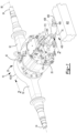
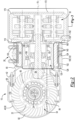
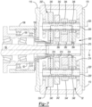
- axle assembly 10 may include a housing assembly 20, a differential assembly 22, at least one axle shaft 24, and an electric motor module 26.
- the axle assembly 10 includes a gear reduction module 30.
- the housing assembly 20 may receive various components of the axle assembly 10.
- the housing assembly 20 may facilitate mounting of the axle assembly 10 to the vehicle.
- the housing assembly 20 may include an axle housing 40 and a differential carrier 42.
- the axle housing 40 may receive and may support the axle shafts 24.
- the axle housing 40 may include a center portion 50 and at least one arm portion 52.
- the center portion 50 may be disposed proximate the center of the axle housing 40.
- the center portion 50 may define a cavity that may at least partially receive the differential assembly 22.
- a lower region of the center portion 50 may at least partially define a sump portion 54 that may contain or collect lubricant 56.
- Lubricant 56 in the sump portion 54 may be splashed by a ring gear of the differential assembly 22 and distributed to lubricate various components.
- the center portion 50 may include a carrier mounting surface 58.
- the carrier mounting surface 58 may facilitate mounting of the differential carrier 42 to the axle housing 40.
- the carrier mounting surface 58 may face toward and may engage the differential carrier 42 and may have a set of holes that may be aligned with corresponding holes on the differential carrier 42. Each hole may receive a fastener, such as a bolt or stud, that may couple the differential carrier 42 to the axle housing 40.
- one or more arm portions 52 may extend from the center portion 50.
- two arm portions 52 may extend in opposite directions from the center portion 50 and away from the differential assembly 22.
- the arm portions 52 may have substantially similar configurations.
- the arm portions 52 may each have a hollow configuration or tubular configuration that may extend around and may receive a corresponding axle shaft 24 and may help separate or isolate the axle shaft 24 or a portion thereof from the surrounding environment.
- An arm portion 52 or a portion thereof may or may not be integrally formed with the center portion 50. It is also contemplated that the arm portions 52 may be omitted.
- the differential carrier 42 may be mounted to the center portion 50 of the axle housing 40.
- the differential carrier 42 may support the differential assembly 22 and may facilitate mounting of the electric motor module 26.
- the differential carrier may include one or more bearing supports that may support a bearing like a roller bearing assembly that may rotatably support the differential assembly 22.
- the differential carrier 42 may also include a mounting flange 60 and a bearing support wall 62.
- the mounting flange 60 may facilitate mounting of the electric motor module 26.
- the mounting flange 60 may be configured as a ring that may extend outward and away from an axis 70 and may extend around the axis 70.
- the mounting flange 60 may include a set of fastener holes that may be configured to receive fasteners, such as a bolt or stud, that may secure the electric motor module 26 to the mounting flange 60.
- the bearing support wall 62 may support bearings that may rotatably support other components of the axle assembly 10.
- the bearing support wall 62 may support bearings that may rotatably support a drive pinion 84, bearings that may rotatably support a rotor of the electric motor module 26, or both.
- the bearing support wall 62 may extend in an axial direction away from the axle housing 40 and may extend around the axis 70.
- the bearing support wall 62 may define a hole that may extend along or around the axis 70 and receive the drive pinion 84 and the bearings that rotatably support the drive pinion 84.
- the bearing support wall 62 may be integrally formed with the differential carrier 42 or may be a separate component that is secured or fastened to the differential carrier 42.
- the differential assembly 22 may be at least partially received in the center portion 50 of the housing assembly 20.
- the differential assembly 22 may be rotatable about a differential axis 80 and may transmit torque to the axle shafts 24 and wheels.
- the differential assembly 22 may be operatively connected to the axle shafts 24 and may permit the axle shafts 24 to rotate at different rotational speeds in a manner known by those skilled in the art.
- the differential assembly 22 may have a ring gear 82 that may have teeth that mate or mesh with the teeth of a gear portion of the drive pinion 84. Accordingly, the differential assembly 22 may receive torque from the drive pinion 84 via the ring gear 82 and transmit torque to the axle shafts 24.
- the drive pinion 84 may provide torque to the ring gear 82.
- the drive pinion 84 may operatively connect the gear reduction module 30 to the differential assembly 22.
- the drive pinion 84 may be rotatable about the axis 70 and may be rotatably supported inside another component, such as the bearing support wall 62.
- the axle shafts 24 may transmit torque from the differential assembly 22 to corresponding wheel hubs and wheels.
- Two axle shafts 24 may be provided such that each axle shaft 24 extends through a different arm portion 52 of axle housing 40.
- the axle shafts 24 may extend along and may be rotatable about an axis, such as the differential axis 80.
- Each axle shaft 24 may have a first end and a second end. The first end may be operatively connected to the differential assembly 22. The second end may be disposed opposite the first end and may be operatively connected to a wheel.
- gear reduction may be provided between an axle shaft 24 and a wheel.
- the electric motor module 26 which may also be referred to as an electric motor, may be mounted to the differential carrier 42 and may be operatively connectable to the differential assembly 22.
- the electric motor module 26 may provide torque to the differential assembly 22 via the drive pinion 84 and a gear reduction module 30 as will be discussed in more detail below.
- the electric motor module 26 may be primarily disposed outside the differential carrier 42.
- the electric motor module 26 may be axially positioned between the axle housing 40 and the gear reduction module 30.
- the electric motor module 26 includes a rotor 106 and may include a motor housing 100, a coolant jacket 102, a stator 104, at least one rotor bearing assembly 108, and a cover 110.
- the motor housing 100 may extend between the differential carrier 42 and the cover 110.
- the motor housing 100 may be mounted to the differential carrier 42 and the cover 110.
- the motor housing 100 may extend from the mounting flange 60 of the differential carrier 42 to the cover 110.
- the motor housing 100 may extend around the axis 70 and may define a motor housing cavity 120.
- the motor housing cavity 120 may be disposed inside the motor housing 100 and may have a generally cylindrical configuration.
- the bearing support wall 62 of the differential carrier 42 may be located inside the motor housing cavity 120.
- the motor housing 100 may extend continuously around and may be spaced apart from the bearing support wall 62.
- the motor housing 100 may have an exterior side 122, an interior side 124, a first end surface 126, a second end surface 128, and one or more ports 130.
- the exterior side 122 may face away from the axis 70 and may define an exterior or outside surface of the motor housing 100.
- the interior side 124 may be disposed opposite the exterior side 122.
- the interior side 124 may be disposed at a substantially constant radial distance from the axis 70 in one or more configurations.
- the first end surface 126 may extend between the exterior side 122 and the interior side 124.
- the first end surface 126 may be disposed at an end of the motor housing 100 that may face toward the differential carrier 42.
- the first end surface 126 may be disposed adjacent to the mounting flange 60 of the differential carrier 42.
- the motor housing 100 and the first end surface 126 may or may not be received inside the mounting flange 60.
- the second end surface 128 may be disposed opposite the first end surface 126. As such, the second end surface 128 may be disposed at an end of the motor housing 100 that may face toward and may engage the cover 110. The second end surface 128 may extend between the exterior side 122 and the interior side 124 and may or may not be received inside the cover 110.
- One or more ports 130 may extend through the motor housing 100.
- the ports 130 may be configured as through holes that may extend from the exterior side 122 to the interior side 124.
- the ports 130 may allow coolant, such as a fluid like water, a water / antifreeze mixture, or the like, to flow to and from the coolant jacket 102 as will be described in more detail below.
- the coolant jacket 102 may help cool or remove heat from the stator 104.
- the coolant jacket 102 may be received in the motor housing cavity 120 of the motor housing 100 and may engage the interior side 124 of the motor housing 100.
- the coolant jacket 102 may extend axially between the differential carrier 42 and the cover 110.
- the coolant jacket 102 may extend axially from the differential carrier 42 to the cover 110.
- the coolant jacket 102 may extend around the axis 70 and the stator 104.
- the stator 104 may be at least partially received in and may be encircled by the coolant jacket 102.
- the coolant jacket 102 may extend in a radial direction from the stator 104 to the interior side 124 of the motor housing 100.
- the coolant jacket 102 may include a plurality of channels 140.
- the channels 140 may extend around the axis 70 and may be disposed opposite the stator 104.
- the channels 140 may be configured with an open side that may face away from the axis 70 and toward the interior side 124 of the motor housing 100.
- Coolant may be provided to the coolant jacket 102 via a first port 130 and may exit the coolant jacket 102 via a second port 130. For instance, coolant may flow from the first port 130 into the channels 140, receive heat from the stator 104 as the coolant flows through the channels 140, and exit at the second port 130.
- One or more baffles may be provided with the coolant jacket 102 that may reverse or change the direction of coolant flow to help route coolant from the first port 130 to the second port 130.
- the stator 104 may be received in the motor housing 100.
- the stator 104 may be received in the motor housing cavity 120.
- the stator 104 may be fixedly positioned with respect to the coolant jacket 102.
- the stator 104 may extend around the axis 70 and may include stator windings that may be received inside and may be fixedly positioned with respect to the coolant jacket 102.
- the rotor 106 may extend around and is rotatable about the axis 70.
- the rotor 106 may be received inside the stator 104, the coolant jacket 102, and the motor housing cavity 120 of the motor housing 100.
- the rotor 106 may be rotatable about the axis 70 with respect to the differential carrier 42 and the stator 104.
- the rotor 106 may be spaced apart from the stator 104 but may be disposed in close proximity to the stator 104.
- the rotor 106 may include magnets or ferromagnetic material that may facilitate the generation of electrical current or may be induction-based.
- the rotor 106 may extend around and may be supported by the bearing support wall 62.
- One or more rotor bearing assemblies 108 may rotatably support the rotor 106.
- a rotor bearing assembly 108 may receive the bearing support wall 62 of the differential carrier 42 and may be received inside of the rotor 106.
- the rotor 106 may be operatively connected to the drive pinion 84.
- a coupling such as a rotor output flange 150 as is best shown in Figure 3 may operatively connect the rotor 106 to the gear reduction module 30, which in turn may be operatively connectable with the drive pinion 84.
- the cover 110 may be mounted to the motor housing 100 and may be disposed opposite the axle housing 40 and the differential carrier 42.
- the cover 110 may be mounted to an end or end surface of the motor housing 100, such as the second end surface 128, that may be disposed opposite the differential carrier 42.
- the cover 110 may be spaced apart from and may not engage the differential carrier 42.
- the cover 110 may be provided in various configurations. In at least one configuration, the cover 110 may include a first side 160 and a second side 162. The first side 160 may face toward and may engage the motor housing 100. The second side 162 may be disposed opposite the first side 160. The second side 162 may face away from the motor housing 100 and may be disposed opposite the motor housing 100.
- the cover 110 may also include or define a motor cover opening that may be a through hole through which the drive pinion 84 may extend.
- the gear reduction module 30 may transmit torque between the electric motor module 26 and the differential assembly 22. As such, the gear reduction module 30 may operatively connect the electric motor module 26 and the differential assembly 22.
- the gear reduction module 30 may be disposed outside of the differential carrier 42 and may be primarily disposed outside of the electric motor module 26 or entirely disposed outside the electric motor module 26, thereby providing a modular construction that may be mounted to the electric motor module 26 when gear reduction is desired.
- the gear reduction module 30 may include a gear reduction module housing 170 that may receive gears of the gear reduction module 30.
- the gear reduction module housing 170 may be provided in various configurations.
- the gear reduction module housing 170 may be a separate component that is mounted to the cover 110 or may be integrally formed with the cover 110.
- the gear reduction module housing 170 may extend from the second side 162 of the cover 110 in a direction that extends away from the electric motor module 26.
- a gear reduction module cover 172 may be disposed on the gear reduction module housing 170 and may be removable to provide access to components located inside the gear reduction module housing 170. It is also contemplated that the gear reduction module housing 170 and the gear reduction module cover 172 may be integrally formed.
- the gear reduction module may be provided in various configurations and may include multiple gear sets that are operatively connected to each other. These gear sets may include a set of drive pinion gears and one or more countershaft gear sets that may have gears that may mesh with the set of drive pinion gears. For clarity, each gear set is designated with a different name below. The configurations discussed below will primarily be discussed in the context of a gear reduction module having two countershaft gear sets (i.e., first and second countershaft gear sets); however, it is to be understood that the second countershaft gear set may be omitted in these configurations.
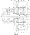
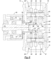
- each gear reduction module configuration can be provided with an axle assembly having components as described above (e.g., with an axle assembly having a housing assembly 20, differential assembly 22, at least one axle shaft 24, electric motor module 26, drive pinion 84, a gear reduction module housing 170, etc.). Accordingly, magnified views are shown in Figures 3-10 to better depict each gear reduction module configuration rather than the remainder of the axle assembly. Each magnified view is a section view along the axis 70. In these figures, torque transmission paths between the electric motor module 26 and drive pinion 84 are represented by straight double-dash lines.
- torque transmission paths are primarily described in the context of transmitting torque from the electric motor module 26 to the drive pinion 84; however, the torque transmission paths may be bidirectional and may facilitate the transmission of torque from the drive pinion 84 to the electric motor module 26 under various operating conditions, such as during regenerative braking.
- the gear reduction module 30 may include a set of drive pinion gears 200, a first countershaft gear set 202, and optionally a second countershaft gear set 204.
- the set of drive pinion gears 200 may include a plurality of gears, some of which may be selectively coupled to the drive pinion 84.
- the set of drive pinion gears 200 includes a first gear 210, a second gear 212, and a third gear 214; however, it is to be understood that a greater or lesser number of gears may be provided.
- the first gear 210 may extend around the axis 70.
- the first gear 210 may have a through hole that may receive the drive pinion 84, a connecting member 270, or both.
- the first gear 210 may have a plurality of teeth that may be arranged around and may extend away from the axis 70.
- the teeth of the first gear 210 may contact and may mate or mesh with teeth of a first countershaft gear that may be provided with the first countershaft gear set 202 and the second countershaft gear set 204 as will be discussed in more detail below.
- the first gear 210 may be operatively connected to the rotor 106 of the electric motor module 26 such that the rotor 106 and the first gear 210 are rotatable together about the axis 70.
- the first gear 210 may be fixedly positioned with respect to the rotor 106 or fixedly coupled to the rotor 106 such that the first gear 210 is not rotatable about the axis 70 with respect to the rotor 106. It is contemplated that the first gear 210 may be fixedly mounted to or integrally formed with the rotor output flange 150. In addition, the first gear 210 may be continuously decoupled from the drive pinion 84 and may be rotatable with respect to the drive pinion 84. As such, a clutch may not connect the first gear 210 to the drive pinion 84 or a connecting member 270 that may extend from the drive pinion 84.
- the connecting member 270 may be received inside the first gear 210 and may be spaced apart from the first gear 210.
- the first gear 210 may be axially positioned along the axis 70 between the second gear 212 and the electric motor module 26.
- the second gear 212 may extend around the axis 70.
- the second gear 212 may have a through hole that may receive the drive pinion 84, a connecting member 270, or both.
- the second gear 212 may have a plurality of teeth that may be arranged around and may extend away from the axis 70.
- the teeth of the second gear 212 may contact and may mate or mesh with teeth of a second countershaft gear that may be provided with the first countershaft gear set 202 and the second countershaft gear set 204 as will be discussed in more detail below.
- the second gear 212 may have a different diameter than the first gear 210 and the third gear 214.
- the second gear 212 may have a larger diameter than the first gear 210 and a smaller diameter than the third gear 214.
- the second gear 212 may be axially positioned along the axis 70 between the first gear 210 and the third gear 214.
- the connecting member 270 may be received inside the second gear 212 and may be spaced apart from the second gear 212 in one or more configurations.
- the third gear 214 may extend around the axis 70.
- the third gear 214 may have a through hole that may receive the drive pinion 84, a connecting member 270, or both.
- the third gear 214 may have a plurality of teeth that may be arranged around and may extend away from the axis 70.
- the teeth of the third gear 214 may contact and may mate or mesh with teeth of a third countershaft gear that may be provided with the first countershaft gear set 202 and the second countershaft gear set 204 as will be discussed in more detail below.
- the third gear 214 may have a different diameter than the first gear 210 and the second gear 212.
- the third gear 214 may have a larger diameter than the first gear 210 and the second gear 212.
- the third gear 214 be axially positioned along the axis 70 further from the electric motor module 26 than the first gear 210 and the second gear 212.
- the connecting member 270 may be received inside the third gear 214 and may be spaced apart from the third gear 214 in one or more configurations.
- a bearing such as a roller bearing may rotatably support a corresponding drive pinion gear.
- the drive pinion 84 or connecting member 270 may be received inside a first bearing, a second bearing, and a third bearing.
- the first bearing may be received inside the first gear 210
- the second bearing may be received inside the second gear 212, and so on to facilitate rotation of the drive pinion 84 with respect to a gear when the gear is not coupled to the drive pinion 84 or the connecting member 270.
- the first countershaft gear set 202 may be in meshing engagement with the set of drive pinion gears 200.
- the first countershaft gear set 202 may be at least partially received in the gear reduction module housing 170.
- the first countershaft gear set 202 may be rotatable about a first countershaft axis 220.
- the first countershaft axis 220 may be disposed parallel or substantially parallel to the axis 70 in one or more embodiments.
- the first countershaft gear set 202 may include a first countershaft 230 and a plurality of gears.
- the plurality of gears of the first countershaft gear set 202 include a first countershaft gear 240, a second countershaft gear 242, and a third countershaft gear 244; however, it is contemplated that a greater number of countershaft gears or a lesser number of countershaft gears may be provided.
- the first countershaft 230 may be rotatable about the first countershaft axis 220.
- the first countershaft 230 may be rotatably supported on the gear reduction module housing 170 by one or more roller bearing assemblies.
- a roller bearing assembly may be located near opposing first and second ends the first countershaft 230.
- the first countershaft 230 may support and be rotatable with the first countershaft gear 240, the second countershaft gear 242, and the third countershaft gear 244.
- the first countershaft gear 240 may be fixedly disposed on the first countershaft 230 or fixedly mounted to the first countershaft 230. As such, the first countershaft gear 240 may rotate about the first countershaft axis 220 with the first countershaft 230 and may not be rotatable with respect to the first countershaft 230.
- the first countershaft gear 240 may have a hole that may receive the first countershaft 230 and may be fixedly coupled to the first countershaft 230.
- the first countershaft gear 240 may extend around the first countershaft axis 220 and may have a plurality of teeth that may be arranged around and may extend away from the first countershaft axis 220.
- the teeth of the first countershaft gear 240 may contact and may mate or mesh with the teeth of the first gear 210.
- the first countershaft gear 240 may be axially positioned along the first countershaft axis 220 between the second countershaft gear 242 of the first countershaft gear set 202 and the electric motor module 26.
- the second countershaft gear 242 may be fixedly disposed on the first countershaft 230 or fixedly mounted to the first countershaft 230. As such, the second countershaft gear 242 may rotate about the first countershaft axis 220 with the first countershaft 230 and may not be rotatable with respect to the first countershaft 230. For example, the second countershaft gear 242 may have a hole that may receive the first countershaft 230 and may be fixedly coupled to the first countershaft 230. The second countershaft gear 242 may extend around the first countershaft axis 220 and may have a plurality of teeth that may be arranged around and may extend away from the first countershaft axis 220.
- the teeth of the second countershaft gear 242 may contact and may mate or mesh with the teeth of the second gear 212.
- the second countershaft gear 242 may have a different diameter than the first countershaft gear 240 and the third countershaft gear 244.
- the second countershaft gear 242 may be axially positioned along the first countershaft axis 220 between the first countershaft gear 240 of the first countershaft gear set 202 and the third countershaft gear 244 of the first countershaft gear set 202.
- the third countershaft gear 244 may be fixedly disposed on the first countershaft 230 or fixedly mounted to the first countershaft 230. As such, the third countershaft gear 244 may rotate about the first countershaft axis 220 with the first countershaft 230 and may not be rotatable with respect to the first countershaft 230. For example, the third countershaft gear 244 may have a hole that may receive the first countershaft 230 and may be fixedly coupled to the first countershaft 230. The third countershaft gear 244 may extend around the first countershaft axis 220 and may have a plurality of teeth that may be arranged around and may extend away from the first countershaft axis 220.
- the teeth of the third countershaft gear 244 may contact and may mate or mesh with the teeth of the third gear 214.
- the third countershaft gear 244 may have a different diameter than the first countershaft gear 240 and the second countershaft gear 242.
- the third countershaft gear 244 may be axially positioned along the first countershaft axis 220 further from the electric motor module 26 than the first countershaft gear 240 and the second countershaft gear 242 of the first countershaft gear set 202.
- the second countershaft gear set 204 may be at least partially received in the gear reduction module housing 170 and may be rotatable about a second countershaft axis 220'.
- the second countershaft axis 220' may be disposed parallel or substantially parallel to the first countershaft axis 220 in one or more embodiments.
- the second countershaft gear set 204 may generally be disposed on an opposite side of the axis 70 from the first countershaft gear set 202 or may be disposed such that the first countershaft axis 220 and the second countershaft axis 220' may be disposed at a common radial distance from the axis 70.
- the first and second countershaft gear sets 202, 204 may be positioned at any suitable rotational angle or position about the axis 70.
- the second countershaft gear set 204 may have the same or substantially the same configuration as the first countershaft gear set 202.
- the second countershaft gear set 204 may include a second countershaft 230' that may be analogous to or may have the same structure as the first countershaft 230.
- the second countershaft gear set 204 may include a plurality of gears that are rotatable with the second countershaft 230'.
- the plurality of gears of the second countershaft gear set 204 include a first countershaft gear 240', a second countershaft gear 242', and a third countershaft gear 244'; however, it is contemplated that a greater number of gears or a lesser number of gears may be provided.
- the first countershaft gear 240', a second countershaft gear 242', and a third countershaft gear 244' of the second countershaft gear set 204 may be analogous to or may have the same structure as the first countershaft gear 240, a second countershaft gear 242, and a third countershaft gear 244, respectively, of the first countershaft gear set 202.
- the first countershaft gear 240', second countershaft gear 242', and third countershaft gear 244' may be arranged along and may be rotatable about a second countershaft axis 220' rather than the first countershaft axis 220 and may be fixed to the second countershaft 230' rather than the first countershaft 230.
- the first gear 210 and the first countershaft gears 240, 240' may provide a different gear ratio than the second gear 212 and the second countershaft gears 242, 242' and may provide a different gear ratio than the third gear 214 and the third countershaft gears 244, 244'.
- the first gear 210 and the first countershaft gears 240, 240' may provide a gear ratio of about 1.68:1
- the second gear 212 and the second countershaft gears 242, 242' may provide a gear ratio of about 1:1
- the third gear 214 and the third countershaft gears 244, 244' may provide a gear ratio of 2:1.
- first countershaft gears 240, 240' may have a larger diameter than the first gear 210, the second countershaft gears 242, 242', and the third countershaft gears 244, 244'.
- the second countershaft gears 242, 242' may have approximately the same diameter as the second gear 212.
- the third gear 214 may have a larger diameter than the third countershaft gears 244, 244'.
- gears or gear pairings may be arranged in different sequences along their respective axes from the configuration shown.
- a gear pairing may provide an "overdrive" gear ratio of less than 1:1.
- gear ratios may be provided that are greater than 1:1, less than 1:1, equal (i.e., 1:1), or combinations thereof.
- the teeth of the drive pinion gears and the countershaft gears may be of any suitable type.
- the meshing teeth of the members of the set of drive pinion gears 200, the gears of the first countershaft gear set 202, and the gears of the second countershaft gear set 204 may have a helical configuration.
- one or more clutches may cooperate with the gear reduction module 30 to provide a desired gear reduction ratio and change the torque transmitted between the electric motor module 26 and the differential assembly 22, and hence between the electric motor module 26 and the axle shafts 24 of the axle assembly 10.
- a clutch may control rotation of one part with respect to another part.
- a clutch may connect and disconnect two parts, such as a driving part and a driven part.
- a clutch may have any suitable configuration.
- a clutch may be configured as a friction clutch, electromagnetic clutch, hydraulic clutch, or the like.
- a clutch may be configured as a slip clutch or a nonslip clutch.
- Slip clutches may be provided in various configurations, an example of which is a multi-plate clutch.
- nonslip clutches may also be provided in various configurations, such as a clutch collar, dog clutch, band clutch, or the like.
- a clutch is represented by a square box that extends between two components.
- the box is checked with an X when the clutch is engaged to couple, connect, or lock the two components to each other.
- the box is empty and is not checked with an X when the clutch is disengaged and the two components are decoupled, disconnected, or unlocked from each other.
- Two rotatable components may rotate together when a clutch connects those two components and may not rotate together when a clutch does not couple or connect those two rotatable components.
- a rotatable component may be inhibited from rotating when a clutch connects a rotatable component to a stationary or a non-rotatable component and may be rotatable with respect to the stationary or non-rotatable component when the clutch does not couple or connect those two components.
- the square boxes may represent separate clutches or may represent clutches that may share a common component.
- a clutch that is configured as a shift collar may have teeth that may mesh with teeth of different components depending on the axial position of the shift collar.
- one square box may represent an approximate location where a shift collar may be coupled to or decoupled from a first component while a second square box may represent an approximate location where the shift collar may be coupled to or decoupled from a second component.
- a clutch may be operated or actuated with any suitable type of actuator in a manner known by those skilled in the art.
- clutches are illustrated. These clutches may be referred to as a first clutch 260 and a second clutch 262.
- the first clutch 260 may selectively couple the second gear 212 to the drive pinion 84.
- the first clutch 260 may connect the second gear 212 to the drive pinion 84 directly or via an intervening component like the connecting member 270 such that the second gear 212 and the drive pinion 84 may be rotatable together about the axis 70 when the first clutch 260 is engaged.
- the first clutch 260 may be disengaged to permit relative rotation between the second gear 212 and the drive pinion 84.
- the first clutch 260 is illustrated as extending between the second gear 212 and the connecting member 270; however, other configurations and positioning are contemplated.
- the connecting member 270 may be omitted and the first clutch 260 may extend from the drive pinion 84.
- the second clutch 262 may selectively couple the third gear 214 to the drive pinion 84.
- the second clutch 262 may connect the third gear 214 to the drive pinion 84 directly or via an intervening component, such as the connecting member 270 such that the third gear 214 and the drive pinion 84 may be rotatable together about the axis 70 when the second clutch 262 is engaged.
- the second clutch 262 may be disengaged to permit relative rotation between the third gear 214 and the drive pinion 84.
- the second clutch 262 is illustrated as extending between the third gear 214 and the connecting member 270; however, other configurations and positioning are contemplated.
- the connecting member 270 may be omitted and the second clutch 262 may extend from the drive pinion 84.
- the first gear ratio may be a high-speed gear ratio.
- the first clutch 260 is engaged and the second clutch 262 is disengaged.
- Torque may be transmitted from the rotor 106 to the first gear 210 such as via the rotor output flange 150, from the first gear 210 to the first countershaft gears 240, 240', from the first countershaft gears 240, 240' to the second countershaft gears 242, 242' via the first and second countershafts 230, 230', respectively, from the second countershaft gears 242, 242' to the second gear 212, and from the second gear 212 to the drive pinion 84 via the first clutch 260 and the connecting member 270, if provided.
- the first gear 210 and the third gear 214 may be rotatable about the axis 70 with respect to the drive pinion 84 when the first gear ratio is provided.
- the second gear ratio may be a low-speed gear ratio.
- the first clutch 260 is disengaged and the second clutch 262 is engaged.
- Torque may be transmitted from the rotor 106 to the first gear 210 such as via the rotor output flange 150, from the first gear 210 to the first countershaft gears 240, 240', from the first countershaft gears 240, 240' to the third countershaft gears 244, 244' via the first and second countershafts 230, 230', respectively, from the third countershaft gears 244, 244' to the third gear 214, and from the third gear 214 to the drive pinion 84 via the second clutch 262 and the connecting member 270, if provided.
- the first gear 210 and the second gear 212 may be rotatable about the axis 70 with respect to the drive pinion 84 when the second gear ratio is provided.
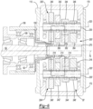
- the gear reduction module 30' may include a set of drive pinion gears 200', a first countershaft gear set 202', and a second countershaft gear set 204'.
- the set of drive pinion gears 200' may include a first gear 210, a second gear 212, and a third gear 214 as previously described.
- the set of drive pinion gears 200' may include one or more additional drive pinion gears, such as a fourth gear 216.
- the fourth gear 216 may extend around the axis 70.
- the fourth gear 216 may have a through hole that may receive the drive pinion 84, the connecting member 270, or both.
- the fourth gear 216 may have a plurality of teeth that may be arranged around and may extend away from the axis 70.
- the teeth of the fourth gear 216 may contact and may mate or mesh with teeth of a fourth countershaft gear that may be provided with the first countershaft gear set 202' and the second countershaft gear set 204' as will be discussed in more detail below.
- the fourth gear 216 may have a different diameter than the first gear 210, the second gear 212, the third gear 214, or combinations thereof.
- the fourth gear 216 may have a larger diameter than the first gear 210, the second gear 212, and the third gear 214. In at least one configuration, the fourth gear 216 may be axially positioned along the axis 70 further from the electric motor module 26 than the third gear 214.
- the first countershaft gear set 202' may include a first countershaft gear 240, a second countershaft gear 242, and a third countershaft gear 244 as previously described.
- the first countershaft gear set 202' may include one or more additional countershaft gears, such as a fourth countershaft gear 246.
- the fourth countershaft gear 246 may be fixedly disposed on the first countershaft 230 or fixedly mounted to the first countershaft 230. As such, the fourth countershaft gear 246 may rotate about the first countershaft axis 220 with the first countershaft 230 and may not be rotatable with respect to the first countershaft 230. For example, the fourth countershaft gear 246 may have a hole that may receive the first countershaft 230 and may be fixedly coupled to the first countershaft 230. The fourth countershaft gear 246 may extend around the first countershaft axis 220 and may have a plurality of teeth that may be arranged around and may extend away from the first countershaft axis 220.
- the teeth of the fourth countershaft gear 246 may contact and may mate or mesh with the teeth of the fourth gear 216.
- the fourth countershaft gear 246 may have a different diameter than the first countershaft gear 240, the second countershaft gear 242, the third countershaft gear 244, or combinations thereof.
- the fourth countershaft gear 246 may be axially positioned along the first countershaft axis 220 further from the electric motor module 26 than the third countershaft gear 244 of the first countershaft gear set 202'.
- the second countershaft gear set 204' may include a first countershaft gear 240', a second countershaft gear 242', and a third countershaft gear 244' as previously described.
- the second countershaft gear set 204' may include one or more additional countershaft gears, such as a fourth countershaft gear 246'.
- the fourth countershaft gear 246' may be fixedly disposed on the second countershaft 230' or fixedly mounted to the second countershaft 230'. As such, the fourth countershaft gear 246' may rotate about the second countershaft axis 220' with the second countershaft 230' and may not be rotatable with respect to the second countershaft 230'.
- the fourth countershaft gear 246' may have a hole that may receive the second countershaft 230' and may be fixedly coupled to the second countershaft 230'.
- the fourth countershaft gear 246' may extend around the second countershaft axis 220' and may have a plurality of teeth that may be arranged around and may extend away from the second countershaft axis 220'.
- the teeth of the fourth countershaft gear 246' may contact and may mate or mesh with the teeth of the fourth gear 216.
- the fourth countershaft gear 246' may have a different diameter than the first countershaft gear 240', the second countershaft gear 242', the third countershaft gear 244', or combinations thereof.
- the fourth countershaft gear 246' may be axially positioned along the second countershaft axis 220' further from the electric motor module 26 than the third countershaft gear 244' of the second countershaft gear set 204'.
- clutches are illustrated. These clutches may be referred to as a first clutch 260, a second clutch 262, and a third clutch 264.
- the first clutch 260 and the second clutch 262 may be the same as previously described.
- the third clutch 264 may selectively couple the fourth gear 216 to the drive pinion 84.
- the third clutch 264 may connect the fourth gear 216 to the drive pinion 84 directly or via an intervening component, such as the connecting member 270 such that the fourth gear 216 and the drive pinion 84 may be rotatable together about the axis 70 when the third clutch 264 is engaged.
- the third clutch 264 may be disengaged to permit relative rotation between the fourth gear 216 and the drive pinion 84.
- the third clutch 264 is illustrated as extending between the fourth gear 216 and the connecting member 270; however, other configurations and positioning are contemplated.
- the connecting member 270 may be omitted and the third clutch 264 may extend from the drive pinion 84.
- the first gear ratio may be a high-speed gear ratio.
- the first clutch 260 is engaged and the second clutch 262 and the third clutch 264 are disengaged.
- Torque may be transmitted from the rotor 106 to the first gear 210 such as via the rotor output flange 150, from the first gear 210 to the first countershaft gears 240, 240', from the first countershaft gears 240, 240' to the second countershaft gears 242, 242' via the first and second countershafts 230, 230', respectively, from the second countershaft gears 242, 242' to the second gear 212, and from the second gear 212 to the drive pinion 84 via the first clutch 260 and the connecting member 270, if provided.
- the first gear 210, the third gear 214, and the fourth gear 216 may be rotatable about the axis 70 with respect to the drive pinion 84 when the
- the second gear ratio may be an intermediate or mid-speed gear ratio that may differ from the first gear ratio.
- the second clutch 262 is engaged and the first clutch 260 and the third clutch 264 are disengaged.
- Torque may be transmitted from the rotor 106 to the first gear 210 such as via the rotor output flange 150, from the first gear 210 to the first countershaft gears 240, 240', from the first countershaft gears 240, 240' to the third countershaft gears 244, 244' via the first and second countershafts 230, 230', respectively, from the third countershaft gears 244, 244' to the third gear 214, and from the third gear 214 to the drive pinion 84 via the second clutch 262 and the connecting member 270, if provided.
- the first gear 210, the second gear 212, and the fourth gear 216 may be rotatable about the axis 70 with respect to the drive pinion 84 when the second gear ratio is provided.
- the third gear ratio may be a low-speed gear ratio that may differ from the first gear ratio and the second gear ratio.
- the third clutch 264 is engaged and the first clutch 260 and the second clutch 262 are disengaged.
- Torque may be transmitted from the rotor 106 to the first gear 210 such as via the rotor output flange 150, from the first gear 210 to the first countershaft gears 240, 240', from the first countershaft gears 240, 240' to the fourth countershaft gears 246, 246' via the first and second countershafts 230, 230', respectively, from the fourth countershaft gears 246, 246' to the fourth gear 216, and from the fourth gear 216 to the drive pinion 84 via the third clutch 264 and the connecting member 270, if provided.
- the first gear 210, the second gear 212, and the third gear 214 may be rotatable about the axis 70 with respect to the drive pinion 84 when the third gear ratio is provided.
- the gear reduction module 30" includes a set of drive pinion gears 200", a first countershaft gear set 202", and a second countershaft gear set 204".
- the set of drive pinion gears 200" includes a first gear 210, a second gear 212, and a third gear 214 as previously described.
- the first gear 210 is selectively connectable to the rotor 106 rather than fixedly coupled to the rotor 106.
- the first gear 210 mate or mesh with the first countershaft gears 240, 240', may be decoupled from the drive pinion 84, and may be rotatable with respect to the drive pinion 84.
- the first countershaft gear set 202" includes a first countershaft gear 240, a second countershaft gear 242, and a third countershaft gear 244 that are fixedly disposed on the first countershaft 230 as previously described.
- the second countershaft gear set 204" includes a first countershaft gear 240', a second countershaft gear 242', and a third countershaft gear 244' that are fixedly disposed on the second countershaft 230' as previously described.
- clutches are illustrated. These clutches may be referred to as a first clutch 360, a second clutch 362, a third clutch 364, and a fourth clutch 366.
- the first clutch 360 selectively connects the first gear 210 to the rotor 106.
- the first clutch 360 may connect the first gear 210 to the rotor 106 directly or via an intervening component like the rotor output flange 150 such that the first gear 210 and the rotor 106 may be rotatable together about the axis 70 when the first clutch 360 is engaged.
- the first clutch 360 may be disengaged to permit relative rotation between the first gear 210 and the rotor 106 and the rotor output flange 150, if provided.
- the first clutch 360 is illustrated as extending between the rotor output flange 150 and the first gear 210.
- the second clutch 362 may be analogous to the first clutch 260 associated with the configuration shown in Figures 3 and 4 . As such, the second clutch 362 selectively connects the second gear 212 to the drive pinion 84, either directly or via an intervening component, such as the connecting member 270.
- the second gear 212 and the drive pinion 84 may be rotatable together about the axis 70 when the second clutch 362 is engaged. Conversely, the second clutch 362 may be disengaged to permit relative rotation between the second gear 212 and the drive pinion 84.
- the third clutch 364 may be analogous to the second clutch 262 associated with the configuration shown in Figures 3 and 4 . As such, the third clutch 364 selectively connects the third gear 214 to the drive pinion 84, either directly or via an intervening component, such as the connecting member 270. The third gear 214 and the drive pinion 84 may be rotatable together about the axis 70 when the third clutch 364 is engaged. Conversely, the third clutch 364 may be disengaged to permit relative rotation between the third gear 214 and the drive pinion 84.
- the fourth clutch 366 may selectively connect the rotor 106 to the second gear 212.
- the fourth clutch 366 may connect the second gear 212 to the rotor 106 directly or via an intervening component, such as the rotor output flange 150 such that the rotor 106 and the second gear 212 may be rotatable together about the axis 70 when the fourth clutch 366 is engaged.
- the fourth clutch 366 may be disengaged to permit relative rotation between the second gear 212 and the rotor 106.
- the fourth clutch 366 is illustrated as extending between the second gear 212 and the rotor output flange 150.
- the first gear ratio may be a high-speed gear ratio.
- the first clutch 360 and the second clutch 362 are engaged and the third clutch 364 and the fourth clutch 366 are disengaged.
- Torque may be transmitted from the rotor 106 to the first gear 210 such as via the rotor output flange 150 and the first clutch 360, from the first gear 210 to the first countershaft gears 240, 240', from the first countershaft gears 240, 240' to the second countershaft gears 242, 242' via the first and second countershafts 230, 230', respectively, from the second countershaft gears 242, 242' to the second gear 212, and from the second gear 212 to the drive pinion 84 via the second clutch 362 and the connecting member 270, if provided.
- first gear 210 may be rotatable with respect to the second gear 212, and the first gear 210 and the third gear 214 may be rotatable about the axis 70 with respect to the drive pinion 84 when the first gear ratio is provided.
- the second gear ratio may be an intermediate or mid-speed gear ratio that may differ from the first gear ratio.
- the third clutch 364 and the fourth clutch 366 are engaged and the first clutch 360 and the second clutch 362 are disengaged.
- Torque may be transmitted from the rotor 106 to the second gear 212 such as via the rotor output flange 150 and the fourth clutch 366, from the second gear 212 to the second countershaft gears 242, 242', from the second countershaft gears 242, 242' to the third countershaft gears 244, 244' via the first and second countershafts 230, 230', respectively, from the third countershaft gears 244, 244' to the third gear 214, and from the third gear 214 to the drive pinion 84 via the third clutch 364 and the connecting member 270, if provided.
- the rotor 106 and the second gear 212 may rotate together about the axis 70, the first gear 210 may not drive the first countershaft gears 240, 240', and the first gear 210 and the second gear 212 may be rotatable about the axis 70 with respect to the drive pinion 84 when the second gear ratio is provided.
- the third gear ratio may be a low-speed gear ratio that may differ from the first gear ratio and the second gear ratio.
- the first clutch 360 and the third clutch 364 are engaged and the second clutch 362 and the fourth clutch 366 are disengaged.
- Torque may be transmitted from the rotor 106 to the first gear 210 such as via the rotor output flange 150 and the first clutch 360, from the first gear 210 to the first countershaft gears 240, 240', from the first countershaft gears 240, 240' to the third countershaft gears 244, 244' via the first and second countershafts 230, 230', respectively, from the third countershaft gears 244, 244' to the third gear 214, and from the third gear 214 to the drive pinion 84 via the third clutch 364 and the connecting member 270, if provided.
- the first gear 210 and the second gear 212 may be rotatable about the axis 70 with respect to each other and with respect to the drive pinion 84 when the third gear ratio is provided.
- the axle assembly 10 may optionally include an isolator support 400.
- the isolator support 400 may help support the end of the axle assembly 10 that is disposed furthest from the axle housing 40 and the differential axis 80.
- the isolator support 400 may extend from the gear reduction module housing 170 or the gear reduction module cover 172 to a cross beam 402 that may be part of the chassis of the vehicle.
- the cross beam 402 may extend in a lateral direction between two frame rails of the vehicle.
- the isolator support 400 may include a first portion 404 that may be mounted on the gear reduction module housing 170 or the gear reduction module cover 172 and a second portion 406 that may be mounted to the cross beam 402.
- the isolator support 400 may allow the first portion 404 to pivot about an isolator mount axis 408 with respect to the second portion 406 and may help limit movement and acceleration of the gear reduction module housing 170.
- a portion of the isolator support 400 may include a resilient member that may be received in a hole in the first portion 404, the second portion 406 or both.
- the first portion 404 or the second portion 406 may be configured as a shock absorber.
- the isolator support 400 may be provided with any of the configurations previously discussed.
- An axle assembly having gear set configurations as described above may provide multiple gear ratios or multiple speeds while providing a more compact package space.
- the gear set configurations may allow the difference between gear ratios to be reduced as compared to a two-speed single planetary gear configuration, which may help improve efficiency of the gear reduction unit and drivability of the vehicle.
- the configurations described above may allow each gear ratio to be a gear reduction with respect to the rotor speed, which may help reduce the rotational speed of the gear sets and helping reduce heating of the roller bearing assemblies associated with the gear sets and improve bearing life.
Landscapes
- Engineering & Computer Science (AREA)
- Mechanical Engineering (AREA)
- General Engineering & Computer Science (AREA)
- Chemical & Material Sciences (AREA)
- Combustion & Propulsion (AREA)
- Transportation (AREA)
- Gear Transmission (AREA)
- Retarders (AREA)
Claims (15)
- Achsenanordnung (10), Folgendes umfassend:einen Elektromotor (26) mit einem Rotor (106), der um eine Achse (70) drehbar ist;ein Antriebsritzel (84), das sich durch den Rotor (106) erstreckt und um die Achse (70) drehbar ist;eine Untersetzungseinheit (30"), die Folgendes umfasst:einen ersten Vorgelegewellenzahnradsatz (202"), der ein erstes, zweites und drittes Vorgelegewellenzahnrad (240, 242, 244) umfasst, die fest an einer ersten Vorgelegewelle (230) montiert sind, sodass das erste, zweite und dritte Vorgelegewellenzahnrad (240, 242, 244) mit der ersten Vorgelegewelle (230) um eine erste Vorgelegewellenachse (220) drehbar sind;einen zweiten Vorgelegewellenzahnradsatz (204"), der ein erstes, zweites und drittes Vorgelegewellenzahnrad (240, 242, 244) umfasst, die fest an einer zweiten Vorgelegewelle (230) montiert sind, sodass das erste, zweite und dritte Vorgelegewellenzahnrad des zweiten Vorgelegewellenzahnradsatzes (204") mit der zweiten Vorgelegewelle (230') um eine zweite Vorgelegewellenachse (220') drehbar sind; undeinen Satz Antriebsritzelzahnräder (200"), der ein erstes, zweites und drittes Zahnrad (210, 212, 214) umfasst, die um die Achse (70) drehbar sind und in das erste, zweite bzw. dritte Vorgelegewellenzahnrad (240, 242, 244) des ersten Vorgelegewellenzahnradsatzes (202") eingreifen und die in das erste, zweite bzw. dritte Vorgelegewellenzahnrad (240, 242, 244) des zweiten Vorgelegewellenzahnradsatzes (204") eingreifen, wobei das erste Zahnrad (210) mit dem Rotor (106) wirkverbindbar ist und das zweite und dritte Zahnrad (212, 214) mit dem Antriebsritzel (84) wirkverbindbar sind;eine erste Kupplung (360), die den Rotor (106) und das erste Zahnrad (210) selektiv miteinander verbindet;eine zweite Kupplung (362), die das zweite Zahnrad (212) und das Antriebsritzel (84) selektiv miteinander verbindet; undeine dritte Kupplung (364), die das dritte Zahnrad (214) und das Antriebsritzel (84) selektiv miteinander verbindet.
- Achsenanordnung nach Anspruch 1, wobei die zweite Kupplung (362) das zweite Zahnrad (212) und das Antriebsritzel (84) über ein Verbindungselement (270), das sich vom Antriebsritzel (84) erstreckt und mit dem Antriebsritzel (84) um die Achse (70) drehbar ist, selektiv miteinander verbindet und wobei die dritte Kupplung (364) das dritte Zahnrad (214) und das Antriebsritzel (84) über das Verbindungselement (270) selektiv miteinander verbindet.
- Achsenanordnung nach Anspruch 2, ferner umfassend eine vierte Kupplung (366), die den Rotor (106) und das zweite Zahnrad (212) selektiv miteinander verbindet.
- Achsenanordnung nach Anspruch 3, wobei die erste Kupplung (360) und die vierte Kupplung (366) nicht gleichzeitig eingreifbar sind und die zweite Kupplung (362) und die dritte Kupplung (364) nicht gleichzeitig eingreifbar sind.
- Achsenanordnung nach Anspruch 3 oder Anspruch 4, wobei ein Drehmoment zwischen dem Elektromotor (26) und dem Antriebsritzel (84) mit einem ersten Übersetzungsverhältnis übertragen wird, wenn die erste Kupplung (360) den Rotor (106) mit dem ersten Zahnrad verbindet und die zweite Kupplung (362) das zweite Zahnrad (212) mit dem Antriebsritzel (84) verbindet.
- Achsenanordnung nach Anspruch 5, wobei die dritte Kupplung (364) das dritte Zahnrad (214) und das Antriebsritzel (84) nicht miteinander verbindet und die vierte Kupplung (366) den Rotor (106) und das zweite Zahnrad (212) nicht miteinander verbindet.
- Achsenanordnung nach einem der Ansprüche 3 bis 5, wobei ein Drehmoment zwischen dem Elektromotor (26) und dem Antriebsritzel (84) mit einem zweiten Übersetzungsverhältnis übertragen wird, wenn die dritte Kupplung (364) das dritte Zahnrad (214) mit dem Antriebsritzel (84) verbindet und die vierte Kupplung (366) den Rotor (106) mit dem zweiten Zahnrad (212) verbindet.
- Achsenanordnung nach Anspruch 7, wobei die erste Kupplung (360) den Rotor (106) und das erste Zahnrad (210) nicht miteinander verbindet und die zweite Kupplung (362) das zweite Zahnrad (212) und das Antriebsritzel (84) nicht miteinander verbindet.
- Achsenanordnung nach einem der Ansprüche 3 bis 8, wobei ein Drehmoment zwischen dem Elektromotor (26) und dem Antriebsritzel (84) mit einem dritten Übersetzungsverhältnis übertragen wird, wenn die erste Kupplung (360) den Rotor (106) mit dem ersten Zahnrad (210) verbindet und die dritte Kupplung (364) das dritte Zahnrad (214) mit dem Antriebsritzel (84) verbindet.
- Achsenanordnung nach Anspruch 9, wobei die zweite Kupplung (362) das zweite Zahnrad (212) und das Antriebsritzel (84) nicht miteinander verbindet und die vierte Kupplung (366) den Rotor (106) und das zweite Zahnrad (212) nicht miteinander verbindet.
- Achsenanordnung nach Anspruch 2, wobei das Verbindungselement (270) im ersten Zahnrad (210) aufgenommen und vom ersten Zahnrad (210) beabstandet ist.
- Achsenanordnung nach Anspruch 2, wobei das erste Zahnrad (210) nicht direkt mit dem Antriebsritzel (84) oder dem Verbindungselement (270) kuppelbar ist.
- Achsenanordnung nach einem der vorstehenden Ansprüche, wobei die erste Kupplung (210) das erste Zahnrad (210) direkt mit dem Rotor (106) verbindet.
- Achsenanordnung nach einem der vorstehenden Ansprüche, wobei die erste Kupplung (210) das erste Zahnrad (210) über einen Rotorausgangsflansch (150) mit dem Rotor (106) verbindet.
- Achsenanordnung nach einem der vorstehenden Ansprüche, wobei der Elektromotor (26) axial zwischen einem Achsengehäuse (40) und dem Untersetzungsmodul (30") positioniert ist.
Priority Applications (1)
| Application Number | Priority Date | Filing Date | Title |
|---|---|---|---|
| EP23155737.2A EP4198343B1 (de) | 2021-02-18 | 2022-02-11 | Achsanordnung mit einem untersetzungsgetriebemodul mit vorgelege-getriebesätzen |
Applications Claiming Priority (1)
| Application Number | Priority Date | Filing Date | Title |
|---|---|---|---|
| US17/178,508 US11220176B1 (en) | 2021-02-18 | 2021-02-18 | Axle assembly having a gear reduction module with countershaft gear sets |
Related Child Applications (2)
| Application Number | Title | Priority Date | Filing Date |
|---|---|---|---|
| EP23155737.2A Division EP4198343B1 (de) | 2021-02-18 | 2022-02-11 | Achsanordnung mit einem untersetzungsgetriebemodul mit vorgelege-getriebesätzen |
| EP23155737.2A Division-Into EP4198343B1 (de) | 2021-02-18 | 2022-02-11 | Achsanordnung mit einem untersetzungsgetriebemodul mit vorgelege-getriebesätzen |
Publications (2)
| Publication Number | Publication Date |
|---|---|
| EP4047241A1 EP4047241A1 (de) | 2022-08-24 |
| EP4047241B1 true EP4047241B1 (de) | 2024-12-18 |
Family
ID=79169254
Family Applications (2)
| Application Number | Title | Priority Date | Filing Date |
|---|---|---|---|
| EP22156376.0A Active EP4047241B1 (de) | 2021-02-18 | 2022-02-11 | Achsanordnung mit einem untersetzungsmodul mit vorgelegegetriebesätzen |
| EP23155737.2A Active EP4198343B1 (de) | 2021-02-18 | 2022-02-11 | Achsanordnung mit einem untersetzungsgetriebemodul mit vorgelege-getriebesätzen |
Family Applications After (1)
| Application Number | Title | Priority Date | Filing Date |
|---|---|---|---|
| EP23155737.2A Active EP4198343B1 (de) | 2021-02-18 | 2022-02-11 | Achsanordnung mit einem untersetzungsgetriebemodul mit vorgelege-getriebesätzen |
Country Status (4)
| Country | Link |
|---|---|
| US (1) | US11220176B1 (de) |
| EP (2) | EP4047241B1 (de) |
| CN (1) | CN114953950B (de) |
| BR (1) | BR102022003032A2 (de) |
Families Citing this family (17)
| Publication number | Priority date | Publication date | Assignee | Title |
|---|---|---|---|---|
| US11001140B1 (en) * | 2020-01-02 | 2021-05-11 | Arvinmeritor Technology, Llc | Axle assembly having a rotor bearing assembly |
| US11679656B1 (en) * | 2022-05-23 | 2023-06-20 | Arvinmeritor Technology, Llc | Electric drive unit and drive axle system |
| US11987137B2 (en) | 2022-07-29 | 2024-05-21 | Arvinmeritor Technology, Llc | Drive axle system and method of control |
| US11976722B2 (en) | 2022-07-29 | 2024-05-07 | Arvinmeritor Technology, Llc | Axle assembly and method of control |
| US11680639B1 (en) | 2022-07-29 | 2023-06-20 | Arvinmeritor Technology, Llc | Drive axle system and method of control |
| US12454183B2 (en) * | 2022-08-22 | 2025-10-28 | Arvinmeritor Technology, Llc | Vehicle having a drive axle system and method of control |
| US12221105B2 (en) | 2022-08-22 | 2025-02-11 | Arvinmeritor Technology, Llc | System and method of controlling torque provided with an axle assembly |
| US11828353B1 (en) | 2022-09-14 | 2023-11-28 | Arvinmeritor Technology, Llc | Axle assembly having a planetary gear set |
| US12249195B2 (en) | 2022-09-21 | 2025-03-11 | Arvinmeritor Technology, Llc | Drive system and method of control |
| US12221013B2 (en) | 2022-09-22 | 2025-02-11 | Arvinmeritor Technology, Llc | Vehicle drive axle system and method of control |
| US11984832B2 (en) | 2022-09-28 | 2024-05-14 | Arvinmeritor Technology, Llc | Drive axle system and method of control |
| US11959548B1 (en) | 2023-03-07 | 2024-04-16 | Arvinmeritor Technology, Llc | Axle assembly and method of control |
| US12403762B2 (en) | 2023-04-10 | 2025-09-02 | Arvinmeritor Technology, Llc | Axle assembly having a shift mechanism |
| CN121219509A (zh) * | 2023-04-19 | 2025-12-26 | 伊顿智能动力有限公司 | 多速同心双轴变速器 |
| US11859718B1 (en) | 2023-04-24 | 2024-01-02 | Arvinmeritor Technology, Llc | Axle assembly having a shift collar |
| US11953090B1 (en) | 2023-06-07 | 2024-04-09 | Arvinmeritor Technology, Llc | Shift control device and a method of controlling an axle assembly |
| US12043099B1 (en) | 2023-10-02 | 2024-07-23 | Arvinmeritor Technology, Llc | Axle assembly having a shift mechanism |
Family Cites Families (26)
| Publication number | Priority date | Publication date | Assignee | Title |
|---|---|---|---|---|
| US1981236A (en) | 1932-12-22 | 1934-11-20 | Charles H Logue | Variable speed power transmitting mechanism |
| DE4129231A1 (de) * | 1991-09-03 | 1993-03-04 | Zahnradfabrik Friedrichshafen | Zahnraederwechselgetriebe mit leistungsteilung auf mehrere vorgelegewellen |
| US5508574A (en) * | 1994-11-23 | 1996-04-16 | Vlock; Alexander | Vehicle transmission system with variable speed drive |
| US6176146B1 (en) | 1998-11-12 | 2001-01-23 | Zf Meritor, Llc | Output shaft arrangement for manual transmission auxiliary boxes |
| DE102005020606A1 (de) | 2005-05-03 | 2006-12-14 | Daimlerchrysler Ag | Getriebe mit im Direktgang abkoppelbarer Vorgelegewelle |
| US7427252B2 (en) * | 2005-10-31 | 2008-09-23 | Gm Global Technology Operations, Inc. | Electrically variable transmission with input split mode and compound split modes |
| JP4572956B2 (ja) | 2008-06-03 | 2010-11-04 | トヨタ自動車株式会社 | 車両の駆動装置 |
| JP6278332B2 (ja) | 2013-04-22 | 2018-02-14 | スズキ株式会社 | 変速機の制御装置 |
| JP6613318B2 (ja) | 2015-05-04 | 2019-11-27 | ボルボトラックコーポレーション | デュアルクラッチトランスミッションの非活動ギアを切り離すための方法及び対応トランスミッション |
| KR101755833B1 (ko) | 2015-09-02 | 2017-07-10 | 현대자동차주식회사 | 차량용 변속기 |
| US20180015816A1 (en) | 2016-07-12 | 2018-01-18 | GM Global Technology Operations LLC | Parallel-shaft transmission assembly with selectable electrification |
| US10500941B2 (en) | 2017-08-18 | 2019-12-10 | Arvinmeritor Technology, Llc | Axle assembly having an electric motor module and a shift mechanism |
| US11273700B2 (en) | 2017-08-18 | 2022-03-15 | Arvinmeritor Technology, Llc | Axle assembly having an electric motor module |
| US10500940B2 (en) | 2017-08-18 | 2019-12-10 | Arvinmeritor Technology, Llc | Axle assembly having an electric motor module and a gear reduction module |
| US11543003B2 (en) * | 2017-12-18 | 2023-01-03 | Eaton Intelligent Power Limited | Electric axle module with 2-speed transmission for hybrid passenger vehicle |
| US10794430B2 (en) * | 2018-06-05 | 2020-10-06 | Arvinmeritor Technology, Llc | Torque transmission apparatus and a collar having concave tooth side surfaces |
| US10808830B2 (en) | 2018-11-30 | 2020-10-20 | Arvinmeritor Technology, Llc | Axle assembly with multiple lubricant chambers |
| US11038396B2 (en) | 2018-11-30 | 2021-06-15 | Arvinmeritor Technology, Llc | Axle assembly having an electric motor module and method of assembly |
| US10704597B2 (en) | 2018-11-30 | 2020-07-07 | Arvinmeritor Technology, Llc | Axle assembly having a bearing preload module |
| US10985635B2 (en) | 2018-11-30 | 2021-04-20 | Arvinmeritor Technology, Llc | Axle assembly having a resolver and a method of assembly |
| US10808834B2 (en) | 2018-11-30 | 2020-10-20 | Arvinmeritor Technology, Llc | Axle assembly and method of control |
| US10801602B2 (en) | 2018-11-30 | 2020-10-13 | Arvinmeritor Technology, Llc | Axle assembly having counterphase planet gears |
| US10935120B2 (en) | 2018-11-30 | 2021-03-02 | Arvinmeritor Technology, Llc | Axle assembly having a spigot bearing assembly |
| US11207976B2 (en) * | 2019-10-07 | 2021-12-28 | Arvinmeritor Technology, Llc | Axle assembly having a multi-speed countershaft transmission |
| CN110843516A (zh) * | 2019-11-04 | 2020-02-28 | 舍弗勒技术股份两合公司 | 车桥系统和机动车辆 |
| US11001140B1 (en) * | 2020-01-02 | 2021-05-11 | Arvinmeritor Technology, Llc | Axle assembly having a rotor bearing assembly |
-
2021
- 2021-02-18 US US17/178,508 patent/US11220176B1/en active Active
-
2022
- 2022-02-11 EP EP22156376.0A patent/EP4047241B1/de active Active
- 2022-02-11 EP EP23155737.2A patent/EP4198343B1/de active Active
- 2022-02-17 CN CN202210147436.8A patent/CN114953950B/zh active Active
- 2022-02-17 BR BR102022003032-4A patent/BR102022003032A2/pt not_active Application Discontinuation
Also Published As
| Publication number | Publication date |
|---|---|
| EP4198343A1 (de) | 2023-06-21 |
| EP4047241A1 (de) | 2022-08-24 |
| CN114953950A (zh) | 2022-08-30 |
| US11220176B1 (en) | 2022-01-11 |
| CN114953950B (zh) | 2025-10-28 |
| EP4198343B1 (de) | 2025-06-25 |
| BR102022003032A2 (pt) | 2022-09-06 |
Similar Documents
| Publication | Publication Date | Title |
|---|---|---|
| EP4047241B1 (de) | Achsanordnung mit einem untersetzungsmodul mit vorgelegegetriebesätzen | |
| EP3805604B1 (de) | Achsanordnung mit einem vorgelegewellengetriebe mit mehreren gängen | |
| EP3805012B1 (de) | Achsanordnung mit achsgehäuse | |
| EP3805605B1 (de) | Achsanordnung mit einem vorgelegewellengetriebe mit mehreren gängen | |
| US11859697B2 (en) | Axle assembly having a multi-speed transmission and a drop gear set | |
| EP3805026A1 (de) | Achsanordnung mit mehrganggetriebe | |
| EP4043746B1 (de) | Achsanordnung mit rotorlageranordnung | |
| EP4155583B1 (de) | Achsanordnung mit einem getriebemodul | |
| US11841066B2 (en) | Axle assembly having a gear reduction module with multiple gear sets | |
| EP4257390B1 (de) | Achsenanordnung mit mehreren geschwindigkeiten und einweg-freilaufkupplung | |
| US11679671B2 (en) | Axle assembly having a gear reduction module with multiple gear sets | |
| EP3798466B1 (de) | Achsanordnung mit getriebemechanismen | |
| EP3879679B1 (de) | Achsanordnung mit einem inneren schmiermittelkanal |
Legal Events
| Date | Code | Title | Description |
|---|---|---|---|
| PUAI | Public reference made under article 153(3) epc to a published international application that has entered the european phase |
Free format text: ORIGINAL CODE: 0009012 |
|
| STAA | Information on the status of an ep patent application or granted ep patent |
Free format text: STATUS: THE APPLICATION HAS BEEN PUBLISHED |
|
| AK | Designated contracting states |
Kind code of ref document: A1 Designated state(s): AL AT BE BG CH CY CZ DE DK EE ES FI FR GB GR HR HU IE IS IT LI LT LU LV MC MK MT NL NO PL PT RO RS SE SI SK SM TR |
|
| STAA | Information on the status of an ep patent application or granted ep patent |
Free format text: STATUS: REQUEST FOR EXAMINATION WAS MADE |
|
| 17P | Request for examination filed |
Effective date: 20230217 |
|
| RBV | Designated contracting states (corrected) |
Designated state(s): AL AT BE BG CH CY CZ DE DK EE ES FI FR GB GR HR HU IE IS IT LI LT LU LV MC MK MT NL NO PL PT RO RS SE SI SK SM TR |
|
| P01 | Opt-out of the competence of the unified patent court (upc) registered |
Effective date: 20230531 |
|
| RIC1 | Information provided on ipc code assigned before grant |
Ipc: F16H 57/037 20120101ALN20240521BHEP Ipc: F16H 57/02 20120101ALN20240521BHEP Ipc: B60B 35/14 20060101ALI20240521BHEP Ipc: B60B 35/12 20060101ALI20240521BHEP Ipc: B60K 1/00 20060101ALI20240521BHEP Ipc: F16H 3/097 20060101ALI20240521BHEP Ipc: F16H 3/095 20060101ALI20240521BHEP Ipc: F16H 3/093 20060101AFI20240521BHEP |
|
| GRAP | Despatch of communication of intention to grant a patent |
Free format text: ORIGINAL CODE: EPIDOSNIGR1 |
|
| STAA | Information on the status of an ep patent application or granted ep patent |
Free format text: STATUS: GRANT OF PATENT IS INTENDED |
|
| INTG | Intention to grant announced |
Effective date: 20240729 |
|
| GRAS | Grant fee paid |
Free format text: ORIGINAL CODE: EPIDOSNIGR3 |
|
| GRAA | (expected) grant |
Free format text: ORIGINAL CODE: 0009210 |
|
| STAA | Information on the status of an ep patent application or granted ep patent |
Free format text: STATUS: THE PATENT HAS BEEN GRANTED |
|
| AK | Designated contracting states |
Kind code of ref document: B1 Designated state(s): AL AT BE BG CH CY CZ DE DK EE ES FI FR GB GR HR HU IE IS IT LI LT LU LV MC MK MT NL NO PL PT RO RS SE SI SK SM TR |
|
| REG | Reference to a national code |
Ref country code: CH Ref legal event code: EP |
|
| REG | Reference to a national code |
Ref country code: DE Ref legal event code: R096 Ref document number: 602022008703 Country of ref document: DE |
|
| REG | Reference to a national code |
Ref country code: IE Ref legal event code: FG4D |
|
| REG | Reference to a national code |
Ref country code: LT Ref legal event code: MG9D |
|
| PG25 | Lapsed in a contracting state [announced via postgrant information from national office to epo] |
Ref country code: HR Free format text: LAPSE BECAUSE OF FAILURE TO SUBMIT A TRANSLATION OF THE DESCRIPTION OR TO PAY THE FEE WITHIN THE PRESCRIBED TIME-LIMIT Effective date: 20241218 |
|
| PG25 | Lapsed in a contracting state [announced via postgrant information from national office to epo] |
Ref country code: FI Free format text: LAPSE BECAUSE OF FAILURE TO SUBMIT A TRANSLATION OF THE DESCRIPTION OR TO PAY THE FEE WITHIN THE PRESCRIBED TIME-LIMIT Effective date: 20241218 |
|
| PG25 | Lapsed in a contracting state [announced via postgrant information from national office to epo] |
Ref country code: BG Free format text: LAPSE BECAUSE OF FAILURE TO SUBMIT A TRANSLATION OF THE DESCRIPTION OR TO PAY THE FEE WITHIN THE PRESCRIBED TIME-LIMIT Effective date: 20241218 |
|
| PG25 | Lapsed in a contracting state [announced via postgrant information from national office to epo] |
Ref country code: NO Free format text: LAPSE BECAUSE OF FAILURE TO SUBMIT A TRANSLATION OF THE DESCRIPTION OR TO PAY THE FEE WITHIN THE PRESCRIBED TIME-LIMIT Effective date: 20250318 |
|
| REG | Reference to a national code |
Ref country code: NL Ref legal event code: MP Effective date: 20241218 |
|
| PG25 | Lapsed in a contracting state [announced via postgrant information from national office to epo] |
Ref country code: LV Free format text: LAPSE BECAUSE OF FAILURE TO SUBMIT A TRANSLATION OF THE DESCRIPTION OR TO PAY THE FEE WITHIN THE PRESCRIBED TIME-LIMIT Effective date: 20241218 Ref country code: GR Free format text: LAPSE BECAUSE OF FAILURE TO SUBMIT A TRANSLATION OF THE DESCRIPTION OR TO PAY THE FEE WITHIN THE PRESCRIBED TIME-LIMIT Effective date: 20250319 |
|
| PG25 | Lapsed in a contracting state [announced via postgrant information from national office to epo] |
Ref country code: RS Free format text: LAPSE BECAUSE OF FAILURE TO SUBMIT A TRANSLATION OF THE DESCRIPTION OR TO PAY THE FEE WITHIN THE PRESCRIBED TIME-LIMIT Effective date: 20250318 |
|
| PG25 | Lapsed in a contracting state [announced via postgrant information from national office to epo] |
Ref country code: NL Free format text: LAPSE BECAUSE OF FAILURE TO SUBMIT A TRANSLATION OF THE DESCRIPTION OR TO PAY THE FEE WITHIN THE PRESCRIBED TIME-LIMIT Effective date: 20241218 |
|
| REG | Reference to a national code |
Ref country code: AT Ref legal event code: MK05 Ref document number: 1752449 Country of ref document: AT Kind code of ref document: T Effective date: 20241218 |
|
| PG25 | Lapsed in a contracting state [announced via postgrant information from national office to epo] |
Ref country code: SM Free format text: LAPSE BECAUSE OF FAILURE TO SUBMIT A TRANSLATION OF THE DESCRIPTION OR TO PAY THE FEE WITHIN THE PRESCRIBED TIME-LIMIT Effective date: 20241218 |
|
| PG25 | Lapsed in a contracting state [announced via postgrant information from national office to epo] |
Ref country code: PL Free format text: LAPSE BECAUSE OF FAILURE TO SUBMIT A TRANSLATION OF THE DESCRIPTION OR TO PAY THE FEE WITHIN THE PRESCRIBED TIME-LIMIT Effective date: 20241218 |
|
| PG25 | Lapsed in a contracting state [announced via postgrant information from national office to epo] |
Ref country code: ES Free format text: LAPSE BECAUSE OF FAILURE TO SUBMIT A TRANSLATION OF THE DESCRIPTION OR TO PAY THE FEE WITHIN THE PRESCRIBED TIME-LIMIT Effective date: 20241218 |
|
| PG25 | Lapsed in a contracting state [announced via postgrant information from national office to epo] |
Ref country code: IS Free format text: LAPSE BECAUSE OF FAILURE TO SUBMIT A TRANSLATION OF THE DESCRIPTION OR TO PAY THE FEE WITHIN THE PRESCRIBED TIME-LIMIT Effective date: 20250418 |
|
| PG25 | Lapsed in a contracting state [announced via postgrant information from national office to epo] |
Ref country code: PT Free format text: LAPSE BECAUSE OF FAILURE TO SUBMIT A TRANSLATION OF THE DESCRIPTION OR TO PAY THE FEE WITHIN THE PRESCRIBED TIME-LIMIT Effective date: 20250421 |
|
| PG25 | Lapsed in a contracting state [announced via postgrant information from national office to epo] |
Ref country code: EE Free format text: LAPSE BECAUSE OF FAILURE TO SUBMIT A TRANSLATION OF THE DESCRIPTION OR TO PAY THE FEE WITHIN THE PRESCRIBED TIME-LIMIT Effective date: 20241218 |
|
| PG25 | Lapsed in a contracting state [announced via postgrant information from national office to epo] |
Ref country code: AT Free format text: LAPSE BECAUSE OF FAILURE TO SUBMIT A TRANSLATION OF THE DESCRIPTION OR TO PAY THE FEE WITHIN THE PRESCRIBED TIME-LIMIT Effective date: 20241218 Ref country code: RO Free format text: LAPSE BECAUSE OF FAILURE TO SUBMIT A TRANSLATION OF THE DESCRIPTION OR TO PAY THE FEE WITHIN THE PRESCRIBED TIME-LIMIT Effective date: 20241218 |
|
| PG25 | Lapsed in a contracting state [announced via postgrant information from national office to epo] |
Ref country code: SK Free format text: LAPSE BECAUSE OF FAILURE TO SUBMIT A TRANSLATION OF THE DESCRIPTION OR TO PAY THE FEE WITHIN THE PRESCRIBED TIME-LIMIT Effective date: 20241218 |
|
| PG25 | Lapsed in a contracting state [announced via postgrant information from national office to epo] |
Ref country code: CZ Free format text: LAPSE BECAUSE OF FAILURE TO SUBMIT A TRANSLATION OF THE DESCRIPTION OR TO PAY THE FEE WITHIN THE PRESCRIBED TIME-LIMIT Effective date: 20241218 |
|
| PG25 | Lapsed in a contracting state [announced via postgrant information from national office to epo] |
Ref country code: IT Free format text: LAPSE BECAUSE OF FAILURE TO SUBMIT A TRANSLATION OF THE DESCRIPTION OR TO PAY THE FEE WITHIN THE PRESCRIBED TIME-LIMIT Effective date: 20241218 |
|
| PG25 | Lapsed in a contracting state [announced via postgrant information from national office to epo] |
Ref country code: SE Free format text: LAPSE BECAUSE OF FAILURE TO SUBMIT A TRANSLATION OF THE DESCRIPTION OR TO PAY THE FEE WITHIN THE PRESCRIBED TIME-LIMIT Effective date: 20241218 |
|
| PG25 | Lapsed in a contracting state [announced via postgrant information from national office to epo] |
Ref country code: MC Free format text: LAPSE BECAUSE OF FAILURE TO SUBMIT A TRANSLATION OF THE DESCRIPTION OR TO PAY THE FEE WITHIN THE PRESCRIBED TIME-LIMIT Effective date: 20241218 |
|
| REG | Reference to a national code |
Ref country code: DE Ref legal event code: R097 Ref document number: 602022008703 Country of ref document: DE |
|
| REG | Reference to a national code |
Ref country code: CH Ref legal event code: PL |
|
| PG25 | Lapsed in a contracting state [announced via postgrant information from national office to epo] |
Ref country code: DK Free format text: LAPSE BECAUSE OF FAILURE TO SUBMIT A TRANSLATION OF THE DESCRIPTION OR TO PAY THE FEE WITHIN THE PRESCRIBED TIME-LIMIT Effective date: 20241218 |
|
| PG25 | Lapsed in a contracting state [announced via postgrant information from national office to epo] |
Ref country code: LU Free format text: LAPSE BECAUSE OF NON-PAYMENT OF DUE FEES Effective date: 20250211 |
|
| PG25 | Lapsed in a contracting state [announced via postgrant information from national office to epo] |
Ref country code: CH Free format text: LAPSE BECAUSE OF NON-PAYMENT OF DUE FEES Effective date: 20250228 |
|
| PLBE | No opposition filed within time limit |
Free format text: ORIGINAL CODE: 0009261 |
|
| STAA | Information on the status of an ep patent application or granted ep patent |
Free format text: STATUS: NO OPPOSITION FILED WITHIN TIME LIMIT |
|
| 26N | No opposition filed |
Effective date: 20250919 |
|
| REG | Reference to a national code |
Ref country code: BE Ref legal event code: MM Effective date: 20250228 |
|
| PG25 | Lapsed in a contracting state [announced via postgrant information from national office to epo] |
Ref country code: FR Free format text: LAPSE BECAUSE OF NON-PAYMENT OF DUE FEES Effective date: 20250218 |
|
| PG25 | Lapsed in a contracting state [announced via postgrant information from national office to epo] |
Ref country code: BE Free format text: LAPSE BECAUSE OF NON-PAYMENT OF DUE FEES Effective date: 20250228 |
|
| PG25 | Lapsed in a contracting state [announced via postgrant information from national office to epo] |
Ref country code: IE Free format text: LAPSE BECAUSE OF NON-PAYMENT OF DUE FEES Effective date: 20250211 |
|
| PGFP | Annual fee paid to national office [announced via postgrant information from national office to epo] |
Ref country code: GB Payment date: 20260227 Year of fee payment: 5 |
|
| PGFP | Annual fee paid to national office [announced via postgrant information from national office to epo] |
Ref country code: DE Payment date: 20260227 Year of fee payment: 5 |