EP4155579B1 - Kettenspannervorrichtung - Google Patents
Kettenspannervorrichtung Download PDFInfo
- Publication number
- EP4155579B1 EP4155579B1 EP22382640.5A EP22382640A EP4155579B1 EP 4155579 B1 EP4155579 B1 EP 4155579B1 EP 22382640 A EP22382640 A EP 22382640A EP 4155579 B1 EP4155579 B1 EP 4155579B1
- Authority
- EP
- European Patent Office
- Prior art keywords
- bolt
- tensioner device
- chain
- chain tensioner
- plunger
- Prior art date
- Legal status (The legal status is an assumption and is not a legal conclusion. Google has not performed a legal analysis and makes no representation as to the accuracy of the status listed.)
- Active
Links
Images

Classifications
-
- F—MECHANICAL ENGINEERING; LIGHTING; HEATING; WEAPONS; BLASTING
- F16—ENGINEERING ELEMENTS AND UNITS; GENERAL MEASURES FOR PRODUCING AND MAINTAINING EFFECTIVE FUNCTIONING OF MACHINES OR INSTALLATIONS; THERMAL INSULATION IN GENERAL
- F16H—GEARING
- F16H7/00—Gearings for conveying rotary motion by endless flexible members
- F16H7/08—Means for varying tension of belts, ropes or chains
-
- B—PERFORMING OPERATIONS; TRANSPORTING
- B62—LAND VEHICLES FOR TRAVELLING OTHERWISE THAN ON RAILS
- B62M—RIDER PROPULSION OF WHEELED VEHICLES OR SLEDGES; POWERED PROPULSION OF SLEDGES OR SINGLE-TRACK CYCLES; TRANSMISSIONS SPECIALLY ADAPTED FOR SUCH VEHICLES
- B62M9/00—Transmissions characterised by use of an endless chain, belt, or the like
- B62M9/04—Transmissions characterised by use of an endless chain, belt, or the like of changeable ratio
- B62M9/06—Transmissions characterised by use of an endless chain, belt, or the like of changeable ratio using a single chain, belt, or the like
- B62M9/10—Transmissions characterised by use of an endless chain, belt, or the like of changeable ratio using a single chain, belt, or the like involving different-sized wheels, e.g. rear sprocket chain wheels selectively engaged by the chain, belt, or the like
- B62M9/12—Transmissions characterised by use of an endless chain, belt, or the like of changeable ratio using a single chain, belt, or the like involving different-sized wheels, e.g. rear sprocket chain wheels selectively engaged by the chain, belt, or the like the chain, belt, or the like being laterally shiftable, e.g. using a rear derailleur
- B62M9/121—Rear derailleurs
- B62M9/126—Chain guides; Mounting thereof
-
- B—PERFORMING OPERATIONS; TRANSPORTING
- B62—LAND VEHICLES FOR TRAVELLING OTHERWISE THAN ON RAILS
- B62M—RIDER PROPULSION OF WHEELED VEHICLES OR SLEDGES; POWERED PROPULSION OF SLEDGES OR SINGLE-TRACK CYCLES; TRANSMISSIONS SPECIALLY ADAPTED FOR SUCH VEHICLES
- B62M9/00—Transmissions characterised by use of an endless chain, belt, or the like
- B62M9/16—Tensioning or adjusting equipment for chains, belts or the like
-
- F—MECHANICAL ENGINEERING; LIGHTING; HEATING; WEAPONS; BLASTING
- F16—ENGINEERING ELEMENTS AND UNITS; GENERAL MEASURES FOR PRODUCING AND MAINTAINING EFFECTIVE FUNCTIONING OF MACHINES OR INSTALLATIONS; THERMAL INSULATION IN GENERAL
- F16H—GEARING
- F16H7/00—Gearings for conveying rotary motion by endless flexible members
- F16H7/06—Gearings for conveying rotary motion by endless flexible members with chains
-
- F—MECHANICAL ENGINEERING; LIGHTING; HEATING; WEAPONS; BLASTING
- F16—ENGINEERING ELEMENTS AND UNITS; GENERAL MEASURES FOR PRODUCING AND MAINTAINING EFFECTIVE FUNCTIONING OF MACHINES OR INSTALLATIONS; THERMAL INSULATION IN GENERAL
- F16H—GEARING
- F16H7/00—Gearings for conveying rotary motion by endless flexible members
- F16H7/08—Means for varying tension of belts, ropes or chains
- F16H2007/0876—Control or adjustment of actuators
- F16H2007/088—Manual adjustment
-
- F—MECHANICAL ENGINEERING; LIGHTING; HEATING; WEAPONS; BLASTING
- F16—ENGINEERING ELEMENTS AND UNITS; GENERAL MEASURES FOR PRODUCING AND MAINTAINING EFFECTIVE FUNCTIONING OF MACHINES OR INSTALLATIONS; THERMAL INSULATION IN GENERAL
- F16H—GEARING
- F16H7/00—Gearings for conveying rotary motion by endless flexible members
- F16H7/08—Means for varying tension of belts, ropes or chains
- F16H2007/0889—Path of movement of the finally actuated member
- F16H2007/0891—Linear path
-
- F—MECHANICAL ENGINEERING; LIGHTING; HEATING; WEAPONS; BLASTING
- F16—ENGINEERING ELEMENTS AND UNITS; GENERAL MEASURES FOR PRODUCING AND MAINTAINING EFFECTIVE FUNCTIONING OF MACHINES OR INSTALLATIONS; THERMAL INSULATION IN GENERAL
- F16H—GEARING
- F16H7/00—Gearings for conveying rotary motion by endless flexible members
- F16H7/08—Means for varying tension of belts, ropes or chains
- F16H2007/0889—Path of movement of the finally actuated member
- F16H2007/0895—Internal to external direction
Definitions
- the invention refers to a chain tensioner device contributing, to the function to which it is designed, with advantages and characteristics that are disclosed in detail thereafter and that means an improvement of the current state-of-the art.
- the object of this invention falls on a device that, applicable to the rear wheel of the motorcycles, bicycles and similar vehicles with chain gear, has the aim to allow regulating the chain tension providing the advantage of facilitating the said operation against the currently known systems for the same aim.
- the field of application of this invention is within the automotive sector, in particular focusing in the industry engaged in manufacturing accessories for motorcycles, bicycles and similar vehicles with chain gear and more concretely in the field of chain tension regulating systems.
- the chain tensioner device that the invention proposes is configurated as the suitable solution to the above stated objective, the characterizing details making it possible and that distinguish it conveniently appearing in the final claims attached to this description.
- the tensioner device of the invention comprises, the features of claim 1.
- the bolt is a headless bolt that remains completely inserted in the part integral with the wheel shaft, being provided at its base, that means, at the opposite end of the pushing tip, of a machined recess for inserting the screwing tool , for example a Torx tool, that is for a type of screw head characterized in that it is six-point star- shaped or an hex or allen type tool, the said recess remaining accessible from the rear part of the shaft, though a hole pierced in the said part to that effect.
- a machined recess for inserting the screwing tool
- a Torx tool that is for a type of screw head characterized in that it is six-point star- shaped or an hex or allen type tool, the said recess remaining accessible from the rear part of the shaft, though a hole pierced in the said part to that effect.
- the device provides the advantage that the device can be activated from the rear part using only one tool instead of two, as it occurs with the preceding nut and safety nut system. In addition, it offers full liberty to rotate the tool 360 degrees or more, without changing the position of the tool.
- Another advantage is that the user can easily make coincident the position on each side, because each full turn of the bolt presents a given number of clicks, that is created by means of the slot on the chain adjustment bolt and the ball of the spring mechanism that makes a click in the said slot.
- Last, another advantage is that only one tool has to be used and not two, because there is no longer a safety nut, because the spring ball mechanism keeps the bolt in its place.
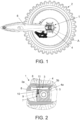
- FIG. 1 shows a side elevation view of an example of rear wheel of a motorcycle with chain gear in which an example of the chain tensioner device of the invention has been incorporated, the general arrangement of the device on one of the sides of the wheel can be seen in a sectional portion of the said area;
- the tensioner device (1) of the invention applicable to be dually incorporated on both sides of the rear wheel (2) of the motorcycle or vehicle on which it is installed, essentially comprises:
- the discretization mechanism of the gap between the first part (4) and the second part (6) comprises in the first part (4), a retractable ball (8) inserted in the end of a plunger (9) with an internal spring (10) that tends to push the said ball (8) outwards the plunger (9); and
- the discretization mechanism of the gap between the first part (4) and the second part (6) comprises
- the said discretization mechanism of the gap between the first part (4) and the second part (6) in addition to keep the bolt (3) in its place, provokes a noise of "click” each time the bolt (3) rotates and the ball (8) passes from one slot (11) to another, when it is screwed or unscrewed through a tool inserted at its base (3b), allowing that the user controls the number of "clicks” to repeat it in an identical manner on each side of the wheel (2).
- the bolt (3) is a headless bolt that remains completely inserted in the part (4) integral with the wheel shaft (5), being provided at its base (3b) with a machined recess for inserting the tool, for example a Torx or hex tool, and that is accessible from the rear part of the shaft (5), though a hole (4a) pierced in the said part (4).
Landscapes
- Engineering & Computer Science (AREA)
- Mechanical Engineering (AREA)
- General Engineering & Computer Science (AREA)
- Chemical & Material Sciences (AREA)
- Combustion & Propulsion (AREA)
- Transportation (AREA)
- Devices For Conveying Motion By Means Of Endless Flexible Members (AREA)
Claims (5)
- Kettenspannvorrichtung, die anwendbar ist, auf beiden Seiten des Hinterrades (2) des Motorrads oder des Fahrzeugs, an das sie installiert wird, doppelt angebracht zu werden, und Folgendes umfasst:- einen Gewindebolzen (3) zum Einstellen der Kette, der in ein Teil (4), das in eine Radwelle (5) integriert ist, die in einer horizontalen Position angeordnet ist, eingesteckt bleibt, derart, dass eine Spitze (3a) des Bolzens (3) gegen ein zweites Teil (6) drückt, das in ein gegenüberliegenden Ende des Zahnrads integriert ist, derart, dass ein Anziehen oder Lösen des Bolzens (3) den Spalt zwischen beiden Teilen (4, 6) zum Regulieren der Kettenspannung bestimmt, und- ein Diskretisierungsmechanismus des Spalts zwischen dem ersten Teil (4) und dem zweiten Teil (6) umfasst mindestens ein einziehbares Element (8), entweder im Bolzen (3) oder im ersten Teil (4), das einen der Reihe von Schlitzen (11), die entweder im Bolzen (3) oder im ersten Teil (4) bereitgestellt sind, berührt und in denselben eingesetzt ist, derart, dass es möglich ist, dass das bei jeder Maßnahme anwendbare Anziehen oder Lösen des Bolzens (3) bekannt ist,dadurch gekennzeichnet, dass
eine Basis (3b) des Gewindebolzens (3) vom hinteren Teil der Welle (5) durch ein Loch (4a), das in das Teil (4) gestanzt ist, erreichbar ist. - Kettenspannvorrichtung nach Anspruch 1, wobei der Diskretisierungsmechanismus des Spalts zwischen dem ersten Teil (4) und dem zweiten Teil (6) Folgendes umfasst:- im ersten Teil (4) eine einziehbare Kugel (8), die in das Ende eines Kolbens (9) eingesteckt ist, mit einer internen Feder (10), die geneigt ist, die Kugel (8) aus dem Kolben (9) zu drücken; und- im Bolzen (3) einen der Reihe von Schlitzen (11), in dem die Kugel (8) berührt und eingesetzt ist.
- Kettenspannvorrichtung nach Anspruch 1, wobei der Diskretisierungsmechanismus des Spalts zwischen dem ersten Teil (4) und dem zweiten Teil (6) Folgendes umfasst:- im Bolzen (3) zwei einziehbare Kugeln (8), die in die Enden eines Kolbens (9) eingesteckt sind, mit einer internen Feder (10), die geneigt ist, die Kugeln (8) aus dem Kolben (9) zu drücken, und- im ersten Teil (4) einen der Reihe von Schlitzen (11), in dem die Kugeln (8) berühren und eingesetzt sind.
- Kettenspannvorrichtung nach einem der vorhergehenden Ansprüche, wobei der Bolzen (3) ein kopfloser Bolzen ist, an dessen Basis (3b) eine bearbeitete Ausnehmung zum Einstecken des Werkzeugs, beispielsweise eines Torx- oder eines Sechskantwerkzeugs, bereitgestellt ist.
- Kettenspannvorrichtung nach einem der vorhergehenden Ansprüche, wobei die Spitze (3a) des Bolzens (3) flach ist.
Applications Claiming Priority (1)
| Application Number | Priority Date | Filing Date | Title |
|---|---|---|---|
| ES202131879U ES1286705Y (es) | 2021-09-22 | 2021-09-22 | Dispositivo tensor de cadena |
Publications (3)
| Publication Number | Publication Date |
|---|---|
| EP4155579A1 EP4155579A1 (de) | 2023-03-29 |
| EP4155579C0 EP4155579C0 (de) | 2024-07-24 |
| EP4155579B1 true EP4155579B1 (de) | 2024-07-24 |
Family
ID=80271588
Family Applications (1)
| Application Number | Title | Priority Date | Filing Date |
|---|---|---|---|
| EP22382640.5A Active EP4155579B1 (de) | 2021-09-22 | 2022-07-05 | Kettenspannervorrichtung |
Country Status (4)
| Country | Link |
|---|---|
| US (1) | US20230091351A1 (de) |
| EP (1) | EP4155579B1 (de) |
| CN (1) | CN115923986A (de) |
| ES (1) | ES1286705Y (de) |
Families Citing this family (1)
| Publication number | Priority date | Publication date | Assignee | Title |
|---|---|---|---|---|
| EP4497971A1 (de) * | 2023-07-28 | 2025-01-29 | BKW Holding B.V. | Kettenspannvorrichtung und schwenkarm und motorrad mit der vorrichtung |
Family Cites Families (7)
| Publication number | Priority date | Publication date | Assignee | Title |
|---|---|---|---|---|
| JP2619641B2 (ja) * | 1987-05-29 | 1997-06-11 | ヤマハ発動機株式会社 | 自動二輪車の後輪片持支持装置 |
| JPH02154847A (ja) * | 1988-12-07 | 1990-06-14 | Nhk Spring Co Ltd | チェーンやベルトなどのテンショナ |
| EP1471284A1 (de) * | 2003-04-22 | 2004-10-27 | Morse Tec Europe S.r.l. | Rückschlagventil für einen hydraulischen Kettenspanner |
| JP2006076502A (ja) * | 2004-09-10 | 2006-03-23 | Honda Motor Co Ltd | 巻き掛け伝動装置 |
| US7637830B2 (en) * | 2007-02-12 | 2009-12-29 | Greilinger John P | Low profile chain and belt tension adjuster |
| EP2998214A1 (de) * | 2014-09-18 | 2016-03-23 | Lightech Srl | Kettenspanner |
| GB201721786D0 (en) * | 2017-12-22 | 2018-02-07 | Agco Corp | Easy adjust tensioner assembly |
-
2021
- 2021-09-22 ES ES202131879U patent/ES1286705Y/es active Active
-
2022
- 2022-07-05 EP EP22382640.5A patent/EP4155579B1/de active Active
- 2022-08-24 CN CN202211020459.9A patent/CN115923986A/zh active Pending
- 2022-08-30 US US17/898,698 patent/US20230091351A1/en active Pending
Also Published As
| Publication number | Publication date |
|---|---|
| ES1286705Y (es) | 2022-05-09 |
| EP4155579A1 (de) | 2023-03-29 |
| CN115923986A (zh) | 2023-04-07 |
| US20230091351A1 (en) | 2023-03-23 |
| ES1286705U (es) | 2022-02-17 |
| EP4155579C0 (de) | 2024-07-24 |
Similar Documents
| Publication | Publication Date | Title |
|---|---|---|
| US5265312A (en) | Hook device in power driven tool | |
| EP4155579B1 (de) | Kettenspannervorrichtung | |
| US5919106A (en) | Quick release derailleur | |
| US9387905B2 (en) | Sprocket for bicycle | |
| US20200398410A1 (en) | Torque wrench | |
| US20040093745A1 (en) | Saw having an angle adjustable blade | |
| US4964762A (en) | Combination of cutter and fastener unit therefor | |
| EP3726956B1 (de) | Landwirtschaftliche maschine | |
| US6279429B1 (en) | Adjustable wrench | |
| US20130095969A1 (en) | Derailleur Guide Device | |
| US8408097B2 (en) | Screwing tool | |
| US3964330A (en) | Chain guide connector device for use in bicycle derailleurs | |
| US6293883B1 (en) | Quick release derailleur | |
| JP2006076502A (ja) | 巻き掛け伝動装置 | |
| US6789451B1 (en) | Securing apparatus of adjustable wrench to prevent movable jaw from trembling | |
| US20230271304A1 (en) | Clutch socket adapter for a tool | |
| US20240336329A1 (en) | Slidingly-engaging two-piece upper chain guide | |
| CA2422563A1 (en) | Pitch adjustment for a tillage shank assembly | |
| EP4495440B1 (de) | Drehmomentbegrenzendes befestigungselement | |
| KR100665889B1 (ko) | 렌치 | |
| KR200286610Y1 (ko) | 개량 몽키 스패너 | |
| KR200375576Y1 (ko) | 렌치 | |
| US6952865B2 (en) | Apparatus for removing heavy duty brake drum bolts | |
| CN216265675U (zh) | 一种电机风扇拆装工装 | |
| DE202006009348U1 (de) | Schraubgerät zur Einstellung von Hohlschrauben |
Legal Events
| Date | Code | Title | Description |
|---|---|---|---|
| PUAI | Public reference made under article 153(3) epc to a published international application that has entered the european phase |
Free format text: ORIGINAL CODE: 0009012 |
|
| STAA | Information on the status of an ep patent application or granted ep patent |
Free format text: STATUS: THE APPLICATION HAS BEEN PUBLISHED |
|
| AK | Designated contracting states |
Kind code of ref document: A1 Designated state(s): AL AT BE BG CH CY CZ DE DK EE ES FI FR GB GR HR HU IE IS IT LI LT LU LV MC MK MT NL NO PL PT RO RS SE SI SK SM TR |
|
| STAA | Information on the status of an ep patent application or granted ep patent |
Free format text: STATUS: REQUEST FOR EXAMINATION WAS MADE |
|
| 17P | Request for examination filed |
Effective date: 20231102 |
|
| GRAP | Despatch of communication of intention to grant a patent |
Free format text: ORIGINAL CODE: EPIDOSNIGR1 |
|
| STAA | Information on the status of an ep patent application or granted ep patent |
Free format text: STATUS: GRANT OF PATENT IS INTENDED |
|
| RIC1 | Information provided on ipc code assigned before grant |
Ipc: F16H 7/08 20060101ALI20240315BHEP Ipc: B62M 9/16 20060101ALI20240315BHEP Ipc: F16H 7/06 20060101AFI20240315BHEP |
|
| RIN1 | Information on inventor provided before grant (corrected) |
Inventor name: SOUCY, PAUL Inventor name: WASS, ANTON |
|
| INTG | Intention to grant announced |
Effective date: 20240404 |
|
| GRAS | Grant fee paid |
Free format text: ORIGINAL CODE: EPIDOSNIGR3 |
|
| GRAA | (expected) grant |
Free format text: ORIGINAL CODE: 0009210 |
|
| STAA | Information on the status of an ep patent application or granted ep patent |
Free format text: STATUS: THE PATENT HAS BEEN GRANTED |
|
| AK | Designated contracting states |
Kind code of ref document: B1 Designated state(s): AL AT BE BG CH CY CZ DE DK EE ES FI FR GB GR HR HU IE IS IT LI LT LU LV MC MK MT NL NO PL PT RO RS SE SI SK SM TR |
|
| REG | Reference to a national code |
Ref country code: GB Ref legal event code: FG4D |
|
| REG | Reference to a national code |
Ref country code: CH Ref legal event code: EP |
|
| REG | Reference to a national code |
Ref country code: IE Ref legal event code: FG4D Ref country code: DE Ref legal event code: R096 Ref document number: 602022004838 Country of ref document: DE |
|
| U01 | Request for unitary effect filed |
Effective date: 20240812 |
|
| U07 | Unitary effect registered |
Designated state(s): AT BE BG DE DK EE FI FR IT LT LU LV MT NL PT SE SI Effective date: 20240827 |
|
| PG25 | Lapsed in a contracting state [announced via postgrant information from national office to epo] |
Ref country code: NO Free format text: LAPSE BECAUSE OF FAILURE TO SUBMIT A TRANSLATION OF THE DESCRIPTION OR TO PAY THE FEE WITHIN THE PRESCRIBED TIME-LIMIT Effective date: 20241024 |
|
| PG25 | Lapsed in a contracting state [announced via postgrant information from national office to epo] |
Ref country code: GR Free format text: LAPSE BECAUSE OF FAILURE TO SUBMIT A TRANSLATION OF THE DESCRIPTION OR TO PAY THE FEE WITHIN THE PRESCRIBED TIME-LIMIT Effective date: 20241025 Ref country code: PL Free format text: LAPSE BECAUSE OF FAILURE TO SUBMIT A TRANSLATION OF THE DESCRIPTION OR TO PAY THE FEE WITHIN THE PRESCRIBED TIME-LIMIT Effective date: 20240724 |
|
| PG25 | Lapsed in a contracting state [announced via postgrant information from national office to epo] |
Ref country code: IS Free format text: LAPSE BECAUSE OF FAILURE TO SUBMIT A TRANSLATION OF THE DESCRIPTION OR TO PAY THE FEE WITHIN THE PRESCRIBED TIME-LIMIT Effective date: 20241124 |
|
| PG25 | Lapsed in a contracting state [announced via postgrant information from national office to epo] |
Ref country code: HR Free format text: LAPSE BECAUSE OF FAILURE TO SUBMIT A TRANSLATION OF THE DESCRIPTION OR TO PAY THE FEE WITHIN THE PRESCRIBED TIME-LIMIT Effective date: 20240724 |
|
| PG25 | Lapsed in a contracting state [announced via postgrant information from national office to epo] |
Ref country code: ES Free format text: LAPSE BECAUSE OF FAILURE TO SUBMIT A TRANSLATION OF THE DESCRIPTION OR TO PAY THE FEE WITHIN THE PRESCRIBED TIME-LIMIT Effective date: 20240724 Ref country code: RS Free format text: LAPSE BECAUSE OF FAILURE TO SUBMIT A TRANSLATION OF THE DESCRIPTION OR TO PAY THE FEE WITHIN THE PRESCRIBED TIME-LIMIT Effective date: 20241024 |
|
| PG25 | Lapsed in a contracting state [announced via postgrant information from national office to epo] |
Ref country code: RS Free format text: LAPSE BECAUSE OF FAILURE TO SUBMIT A TRANSLATION OF THE DESCRIPTION OR TO PAY THE FEE WITHIN THE PRESCRIBED TIME-LIMIT Effective date: 20241024 Ref country code: PL Free format text: LAPSE BECAUSE OF FAILURE TO SUBMIT A TRANSLATION OF THE DESCRIPTION OR TO PAY THE FEE WITHIN THE PRESCRIBED TIME-LIMIT Effective date: 20240724 Ref country code: NO Free format text: LAPSE BECAUSE OF FAILURE TO SUBMIT A TRANSLATION OF THE DESCRIPTION OR TO PAY THE FEE WITHIN THE PRESCRIBED TIME-LIMIT Effective date: 20241024 Ref country code: IS Free format text: LAPSE BECAUSE OF FAILURE TO SUBMIT A TRANSLATION OF THE DESCRIPTION OR TO PAY THE FEE WITHIN THE PRESCRIBED TIME-LIMIT Effective date: 20241124 Ref country code: HR Free format text: LAPSE BECAUSE OF FAILURE TO SUBMIT A TRANSLATION OF THE DESCRIPTION OR TO PAY THE FEE WITHIN THE PRESCRIBED TIME-LIMIT Effective date: 20240724 Ref country code: GR Free format text: LAPSE BECAUSE OF FAILURE TO SUBMIT A TRANSLATION OF THE DESCRIPTION OR TO PAY THE FEE WITHIN THE PRESCRIBED TIME-LIMIT Effective date: 20241025 Ref country code: ES Free format text: LAPSE BECAUSE OF FAILURE TO SUBMIT A TRANSLATION OF THE DESCRIPTION OR TO PAY THE FEE WITHIN THE PRESCRIBED TIME-LIMIT Effective date: 20240724 |
|
| PG25 | Lapsed in a contracting state [announced via postgrant information from national office to epo] |
Ref country code: SM Free format text: LAPSE BECAUSE OF FAILURE TO SUBMIT A TRANSLATION OF THE DESCRIPTION OR TO PAY THE FEE WITHIN THE PRESCRIBED TIME-LIMIT Effective date: 20240724 Ref country code: RO Free format text: LAPSE BECAUSE OF FAILURE TO SUBMIT A TRANSLATION OF THE DESCRIPTION OR TO PAY THE FEE WITHIN THE PRESCRIBED TIME-LIMIT Effective date: 20240724 |
|
| PG25 | Lapsed in a contracting state [announced via postgrant information from national office to epo] |
Ref country code: CZ Free format text: LAPSE BECAUSE OF FAILURE TO SUBMIT A TRANSLATION OF THE DESCRIPTION OR TO PAY THE FEE WITHIN THE PRESCRIBED TIME-LIMIT Effective date: 20240724 |
|
| PG25 | Lapsed in a contracting state [announced via postgrant information from national office to epo] |
Ref country code: SK Free format text: LAPSE BECAUSE OF FAILURE TO SUBMIT A TRANSLATION OF THE DESCRIPTION OR TO PAY THE FEE WITHIN THE PRESCRIBED TIME-LIMIT Effective date: 20240724 |
|
| PLBE | No opposition filed within time limit |
Free format text: ORIGINAL CODE: 0009261 |
|
| STAA | Information on the status of an ep patent application or granted ep patent |
Free format text: STATUS: NO OPPOSITION FILED WITHIN TIME LIMIT |
|
| 26N | No opposition filed |
Effective date: 20250425 |
|
| U20 | Renewal fee for the european patent with unitary effect paid |
Year of fee payment: 4 Effective date: 20250722 |