EP4155558B1 - Befestigungsanordnung zur verankerung in einem ankerloch - Google Patents
Befestigungsanordnung zur verankerung in einem ankerloch Download PDFInfo
- Publication number
- EP4155558B1 EP4155558B1 EP22193378.1A EP22193378A EP4155558B1 EP 4155558 B1 EP4155558 B1 EP 4155558B1 EP 22193378 A EP22193378 A EP 22193378A EP 4155558 B1 EP4155558 B1 EP 4155558B1
- Authority
- EP
- European Patent Office
- Prior art keywords
- anchor rod
- anchor
- centering
- fastening arrangement
- arrangement according
- Prior art date
- Legal status (The legal status is an assumption and is not a legal conclusion. Google has not performed a legal analysis and makes no representation as to the accuracy of the status listed.)
- Active
Links
Images


Classifications
-
- F—MECHANICAL ENGINEERING; LIGHTING; HEATING; WEAPONS; BLASTING
- F16—ENGINEERING ELEMENTS AND UNITS; GENERAL MEASURES FOR PRODUCING AND MAINTAINING EFFECTIVE FUNCTIONING OF MACHINES OR INSTALLATIONS; THERMAL INSULATION IN GENERAL
- F16B—DEVICES FOR FASTENING OR SECURING CONSTRUCTIONAL ELEMENTS OR MACHINE PARTS TOGETHER, e.g. NAILS, BOLTS, CIRCLIPS, CLAMPS, CLIPS OR WEDGES; JOINTS OR JOINTING
- F16B13/00—Dowels or other devices fastened in walls or the like by inserting them in holes made therein for that purpose
- F16B13/14—Non-metallic plugs or sleeves; Use of liquid, loose solid or kneadable material therefor
- F16B13/141—Fixing plugs in holes by the use of settable material
-
- F—MECHANICAL ENGINEERING; LIGHTING; HEATING; WEAPONS; BLASTING
- F16—ENGINEERING ELEMENTS AND UNITS; GENERAL MEASURES FOR PRODUCING AND MAINTAINING EFFECTIVE FUNCTIONING OF MACHINES OR INSTALLATIONS; THERMAL INSULATION IN GENERAL
- F16B—DEVICES FOR FASTENING OR SECURING CONSTRUCTIONAL ELEMENTS OR MACHINE PARTS TOGETHER, e.g. NAILS, BOLTS, CIRCLIPS, CLAMPS, CLIPS OR WEDGES; JOINTS OR JOINTING
- F16B43/00—Washers or equivalent devices; Other devices for supporting bolt-heads or nuts
- F16B43/02—Washers or equivalent devices; Other devices for supporting bolt-heads or nuts with special provisions for engaging surfaces which are not perpendicular to a bolt axis or do not surround the bolt
Definitions
- the invention relates to a fastening arrangement for anchoring in an anchor hole with the features of the preamble of claim 1.
- the disclosure document DE 32 04 417 A1 discloses a fastening arrangement with an anchor rod that is anchored in an anchor hole with a hardening mass, for example a cement mortar.
- a hardening mass for example a cement mortar.
- two centering rings are arranged on the anchor rod at a front end and at a distance from the front end, which have several diagonally protruding and radially springy spring tongues distributed over a circumference.
- the centering rings are arranged on the anchor rod in such a way that the spring tongues protrude diagonally in the direction of a rear end of the anchor rod.
- a rear of the two centering rings is arranged on the anchor rod in such a way that it is in the anchor hole when the anchor rod is introduced into the anchor hole.
- the spring tongues of the two centering rings are elastically supported radially on a hole wall of the anchor hole and thereby center the anchor rod in the anchor hole.
- the object of the invention is to reduce the risk of axial displacement of a centering ring on an anchor rod when the anchor rod is inserted into an anchor hole.
- Such axial displacement on the anchor rod can result in the centering ring not reaching the anchor hole, but being held back at an opening of the anchor hole, the borehole mouth, i.e. the outer, accessible end of the blind hole opposite the bottom of the borehole into which the anchor rod is inserted.
- the fastening arrangement according to the invention is designed for anchoring, that is to say for fastening an anchor rod in an anchor hole in an anchor base with a hardening mass such as a mortar, also a one-component or multi-component synthetic resin mortar. After hardening, the hardening mass is referred to as the "hardened mass”.
- the anchor rod is in particular a threaded rod.
- the anchor base is, for example, stone, rock, masonry or concrete, into which the anchor hole is or is drilled.
- the anchor hole extends from a borehole mouth, i.e. the rear end of the anchor hole accessible from the outside, to a borehole base, which forms the front end of the anchor hole, which can therefore also be referred to as a blind hole.
- a centering element is arranged on a front end of the anchor rod, which has at least one contact element that is intended to rest on a hole wall of the anchor hole when the anchor rod is inserted into the anchor hole with the front end with the centering element first.
- a centering ring is arranged on the anchor rod at an axial distance from the front end, the inside of which rests against the anchor rod all the way around or at least in places. If the anchor rod is a threaded rod, the centering ring rests on the outside of a thread on the anchor rod, for example.
- the centering ring is or will be arranged on the anchor rod in such a way that it is located in the anchor hole when the anchor rod is inserted into the anchor hole, preferably at a distance from the borehole mouth that is in particular at least 10% of the diameter of the anchor hole, so that a flat contact of the centering ring on the wall of the anchor hole is ensured.
- the centering ring defines an imaginary cylinder that is concentric with the anchor rod.
- the cylinder is an imaginary cylinder that is concentric with the anchor rod, which the centering ring touches at least one and preferably at several points that are evenly or unevenly distributed over a circumference, but does not penetrate radially outwards anywhere. This means that the centering ring is located completely within the cylinder.
- the points at which the centering ring touches the cylinder can be in a common radial plane or offset from one another in the axial direction.
- the centering ring can also touch the cylinder all the way around with or without interruptions.
- a diameter of the cylinder is larger than a diameter of the anchor rod and, in the case of a threaded rod as an anchor rod, larger than an outer diameter of the thread of the anchor rod or threaded rod.
- the imaginary cylinder therefore encloses the anchor rod with a circumferential annular gap which, in the case of a cylindrical anchor rod, is the same width at every circumferential point.
- the at least one contact element of the centering element or at least a part of the at least one contact element is located in the undeformed state of the centering element including the at least one contact element outside the surrounding cylinder of the centering ring.
- the at least one contact element of the centering element is - preferably elastically, but possibly also plastically - movable in the radial direction to the anchor rod so far that it is located within the surrounding cylinder of the centering ring.
- a hole wall of the anchor hole acts on the at least one contact element of the centering element, which is arranged on the anchor rod at the front end, the at least one contact element radially inward in the direction of the anchor rod such that the contact element rests on the inside of the hole wall of the anchor hole.
- the anchor rod with the centering element at its front end and the centering ring at the axial distance from the front end is inserted with the front end first into the anchor hole so deeply that the centering ring is in the anchor hole, preferably at a distance from the borehole mouth that is in particular at least 10% of the diameter of the anchor hole.
- the anchor hole has a diameter that is at least as large as the circumference of the centering ring and preferably slightly larger.
- a radius of the anchor hole is at most as large and preferably smaller than a radial distance of the part of the at least one contact element of the centering element that is radially furthest away from the longitudinal axis of the anchor rod.
- the centering element is designed in such a way that it ensures an annular gap surrounding the anchor rod in the anchor hole in order to ensure that a hardening mass with which the anchor rod is anchored in the anchor hole completely surrounds the anchor rod in the anchor hole, in particular over the entire length of the anchor rod in the anchor hole.
- the centering element is designed in such a way that it centers the anchor rod in the anchor hole, which in the case of a cylindrical anchor rod means an annular gap with a constant width over the circumference.
- the centering element preferably has at least three radially movable contact elements which, in the undeformed state, penetrate the surrounding cylinder of the centering ring and protrude radially outwards beyond the surrounding cylinder.
- the hole wall of the anchor hole acts on the at least three contact elements radially inwards in the direction of the anchor rod, whereby the contact elements rest on the inside of the hole wall of the anchor hole and center the front end of the anchor rod in the anchor hole.
- the contact elements of the centering element are preferably offset from one another by less than 180° such that at least one contact element is located outside an imaginary semicircle coaxial with the anchor rod, in which at least two other contact elements are located.
- a design of the centering element with two radially movable contact elements is also possible, which are preferably arranged opposite each other on the centering element and which center the front end of the anchor rod in the anchor hole.
- the diameter of the anchor hole into which the anchor rod is inserted with the centering element at its front end and with the centering ring arranged at an axial distance from the front end is preferably larger than the diameter of the centering ring's surrounding cylinder so that friction between the hole wall and the centering ring is low when the anchor rod is inserted into the anchor hole and the centering ring does not move axially on the anchor rod.
- a radius of the anchor hole is preferably smaller or at least not larger than the radial distance of the part of the contact element(s) of the centering element that is radially furthest away from the longitudinal axis of the anchor rod.
- One embodiment of the invention provides for anchoring the anchor rod with a hardening or hardened mass such as a synthetic resin mortar in the anchor hole.
- the hardening mass is introduced into the anchor hole in a flowable state and distributed in the annular gap surrounding the anchor rod in the anchor hole in such a way that the hardening mass or the mass hardened after hardening anchors the anchor rod in the anchor hole or in the anchor base.
- the hardening mass can be introduced into the anchor hole before or after the anchor rod, but is preferably introduced beforehand.
- the at least one contact element of the centering element preferably springs radially to a surrounding cylinder of the centering element about a tangential axis of the surrounding cylinder and to an axis parallel to the surrounding cylinder, which is referred to here as the "parallel axis".
- the tangential axis of the at least one contact element is preferably arranged outside a circumferential center of the at least one contact element and preferably on a longitudinal edge of the at least one contact element. As a result, more than half and preferably the entire contact element pivots radially inward about the tangential axis, which results in a large radial path of the contact element for a given pivot angle.
- a development of the contact element in a plane is L-shaped.
- “Development” means an expansion of the contact element in a plane, i.e. a curvature of the contact element in the circumferential direction is reduced to "zero".
- the contact element is L-shaped when viewed radially to the centering element.
- the at least one contact element has a radially inward connection into which it merges with a tangential bend, which in particular also defines the tangential axis about which the contact element can be pivoted radially inward.
- an embodiment of the invention provides axial passages for the hardening mass in a flowable state between the connections of two contact elements adjacent in the circumferential direction.
- an outer surface of the at least one contact element of the centering element facing away from the anchor rod extends obliquely outwards.
- the centering element has an axial abutment that engages over a front end of the anchor rod when the centering element is arranged on the anchor rod at the front end.
- the abutment ensures that the centering element is held axially at the front end of the anchor rod.
- the centering ring has one or preferably several inwardly projecting thread engagement elements which, when a threaded rod is used as an anchor rod, engage between threads of a thread of the anchor rod or threaded rod and improve an axial hold of the centering ring on the anchor rod.
- the thread engagement elements can be designed, for example, as ribs, teeth or the like running in a circumferential direction, which project radially inward from an inner side of the centering ring facing the anchor rod.
- one embodiment of the invention provides recesses in both front edges of the centering ring as longitudinal passages for the flowable mass.
- the recesses are preferably offset from one another; in a longitudinal direction they can overlap one another in such a way that the flowable mass can flow into the recesses at one front edge, then flow in the circumferential direction to another recess and flow out through these recesses at another front edge of the centering ring.
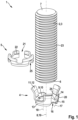
- the fastening arrangement 1 according to the invention shown in FIG. 1 has a threaded rod 2 made of steel as an anchor rod 3 and a centering element 4 which is Figures 3 and 4 shown as a single part, and a centering ring 5, which is in Figure 5 shown as a single part.
- the ends of the anchor rod 3 are referred to here as the front end 6 and the rear end 7, according to the planned direction of insertion for the anchor rod 3 into an anchor hole, with the centering element 4 being placed on the front end 6 the anchor rod 3.
- the anchor rod 3 has a longitudinal axis 8.
- the centering element 4 has a circular end plate 9 which bears against an end face on the front end 6 of the anchor rod 3 when the centering element 4 is arranged as intended on the front end 6 of the anchor rod 3.
- the end plate 9 forms an axial abutment 10 which engages over the front end 6 of the anchor rod 3 and holds the centering element 4 axially in one direction on the anchor rod 3 such that the centering element 4 cannot be displaced backwards in the direction of the rear end 7 on the anchor rod 3.
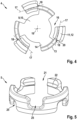
- the centering element 4 has three contact elements 11 on its circumference, which are L-shaped when viewed radially to the centering element 4.
- unfoldings of the contact elements 11 in a plane have an L-shape.
- the unfolding is an imaginary bend of the contact elements 11 curved in a circumferential direction of the centering element 4 in a plane.
- An axially parallel leg 12 of the contact elements 11 and thus also an outer surface of the contact elements 11 runs over approximately half a length of the axially parallel legs 12 obliquely at an acute angle to a central axis 19 of the centering element 4 and obliquely away from the end plate 9 radially outwards.
- the central axis 19 passes vertically through a center of the end plate 9 and coincides with the longitudinal axis 8 of the anchor rod 3 when the centering element 4 is arranged as intended with its end plate 9 resting on the front end 6 of the anchor rod 3.
- the circumferential leg 13 is connected to the end plate 9 of the centering element 4 by a radially inward connection 14, into which the circumferential leg 13 merges via a tangential bend 15.
- the connections 14, which connect the end plate 9 of the centering element 4 to the contact elements 11, protrude radially outward from the end plate 9 at three circumferential points.
- the centering element 4 including the connections 14 and the contact elements 11 is injection-molded in one piece from plastic.
- the contact elements 11 are evenly distributed over the circumference of the front disk 9 or the centering element 4, but an arrangement of the contact elements 11 distributed unevenly over the circumference or a number other than three contact elements 11 is also possible (not shown).
- the centering element 4 can have more than three or only two contact elements 11, which are then preferably arranged opposite one another.
- a design of the centering element 4 with only one contact element 11 is also conceivable (not shown).
- the invention does not exclude a production of the centering element 4 with the contact elements 11 other than from plastic or as a single piece.
- a free space extending in the circumferential direction around the end plate 9 between connections 14 of adjacent contact elements 11 forms an axial passage 16 for the passage of a flowable mass.
- the parallel axes 18 run along longitudinal edges 20 of the axially parallel legs 12 of the L-shaped contact elements 11 on the side where the axially parallel legs 12 merge into the circumferential legs 3. Viewed in the circumferential direction, the parallel axes 18 are therefore located outside the circumferential centers of the axially parallel legs 12 of the contact elements 11 on the longitudinal edges 20 of the axially parallel legs 12. Due to the elastic pivoting about the tangential axes 17 and about the parallel axes 18, the contact elements 11 spring in the radial direction towards the anchor rod 3 when the centering element 4 is arranged on the front end 6 of the anchor rod 3.
- the centering ring 5 has an axially continuous opening 21 at a circumferential point such that it can be placed not only axially but also radially on the anchor rod 3.
- a centering ring is also possible which is closed in the circumferential direction and which can only be placed axially on the anchor rod 3 (not shown).
- the centering ring 5 has first threaded engagement elements 22 which engage in a thread 23 of the threaded rod 2 forming the anchor rod 3 when the centering ring 5 is placed on the anchor rod 3.
- the first threaded engagement elements 22 are designed as ribs with a triangular cross-section running in the circumferential direction, which protrude radially inward from an inner side of the centering ring 5 facing the anchor rod 3.
- the centering element 4 has second threaded engagement elements 24 on the inner sides of the contact elements 11 facing the anchor rod 3, by means of which the centering element 4 can be screwed or clipped onto the anchor rod 3, so that it is held, especially before being inserted into an anchor hole.
- the centering ring 5 has recesses as longitudinal passages 25 for the flowable mass, which are offset from one another in the circumferential direction and in the axial direction are more than half as long as the centering ring 5 is high in the axial direction, such that the longitudinal passages 25 offset from one another in the circumferential direction overlap in the axial direction.
- This allows the flowable mass to flow from one side into the longitudinal passages 25 of the centering ring 5 and then flows between threads of the thread 23 of the threaded rod 2 forming the anchor rod 3 in the circumferential direction to a next longitudinal passage 25, where the flowable mass exits on another side of the centering ring 5.
- the centering element 4 is placed on the front end 6 of the anchor rod 3.
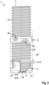
- the centering ring 5 is placed on the anchor rod 3 at an axial distance from the front end 6, which is dimensioned such that the centering ring 5 is located in the anchor hole 26, preferably at or near an opening of the anchor hole 26, i.e. the borehole mouth, when the anchor rod 3 is inserted into the anchor hole 26, in the embodiment at a distance from the borehole mouth that is slightly more than 10% of the diameter of the anchor hole ( Figure 6 ).
- the inside of the centering ring 5 rests on the anchor rod 3, in the embodiment on the outside on the thread 23 of the anchor rod 3.
- a synthetic resin mortar or another hardening mass 28 in a flowable state is introduced into the anchor hole 26 and preferably then the anchor rod 3 with its front end 6, on which the centering element 4 is arranged, is introduced into the anchor hole 26 until the centering ring 5 is also in the anchor hole 26.
- the anchor rod 3 acts on the hardening mass 28, similar to a piston, in the direction of a base of the anchor hole 26 and simultaneously and/or subsequently displaces it axially in an annular gap 29 surrounding the anchor rod 3 in the anchor hole 26 in the direction of the mouth of the anchor hole 26.
- the hardening mass flows through the axial passages 16 between the connections 14 of the contact elements 11 of the centering element 4 and is mixed in a similar way to a static mixer.
- the hardening mass 28 flows into the longitudinal passages 25 in the front edge of the centering ring 5 facing the centering element 4, from there further between the threads of the thread 23 of the anchor rod 3 in the circumferential direction to the longitudinal passages 25 in the front edge of the centering ring 5 facing away from the centering element 4 and from there further to the mouth of the anchor hole 26 such that the annular gap 29 enclosing the anchor rod 3 in the anchor hole 26 is essentially completely filled with the hardening mass 28.
- An outer diameter of the centering ring 5 is not larger and preferably slightly smaller than a hole diameter of the anchor hole 26, so that friction between the centering ring 5 and a hole wall of the anchor hole 26 is low and the centering ring 5 does not move axially on the anchor rod 3 when the anchor rod 3 is inserted into the anchor hole 26.
- the first thread engagement elements 22 engaging in the thread 23 of the anchor rod 3 improve the axial hold of the centering ring 5 on the anchor rod 3 such that the centering ring 5 does not move axially on the anchor rod 3 when the anchor rod 3 is inserted into the anchor hole 26 due to friction with the hole wall of the anchor hole 26 or due to the hardening mass that flows through the centering ring 5 through the longitudinal passages 25 and between the threads.
- the contact elements 11 of the centering element 4 penetrate an imaginary cylinder 30 of the centering ring 5, which has the same diameter as the outer diameter of the centering ring 5 and which coaxially encloses the anchor rod 3.
- parts of the contact elements 11, which run at an acute angle to the longitudinal axis 7, are located radially outside the surrounding cylinder 30.
- the contact elements 11 protrude so far radially outward from the anchor rod 3 that when they are introduced into the anchor hole 26, they are elastically bent radially inward by the anchor hole 26 in such a way that the contact elements 11 rest against the hole wall of the anchor hole 26 with a radial prestress and center the front end 6 of the anchor rod 3 in the anchor hole 26.
- the undeformed state of one of the contact elements 11 is in Figure 6 drawn with dashed lines on the right side of the centering ring 5. During the elastic, radial inward pressure, the contact elements 11 pivot about the tangential axes 17 and the parallel axes 18.
- the hardening mass 28, which is then referred to as hardened mass 28, holds, i.e. anchors, the anchor rod 3 in the anchor hole 26.
Landscapes
- Engineering & Computer Science (AREA)
- General Engineering & Computer Science (AREA)
- Mechanical Engineering (AREA)
- Joining Of Building Structures In Genera (AREA)
- Dowels (AREA)
Description
- Die Erfindung betrifft eine Befestigungsanordnung zur Verankerung in einem Ankerloch mit den Merkmalen des Oberbegriffs des Anspruchs 1.
- Die Offenlegungsschrift
DE 32 04 417 A1 offenbart eine Befestigungsanordnung mit einer Ankerstange, die mit einer aushärtenden Masse, beispielsweise einem Zementmörtel, in einem Ankerloch verankert wird. Um die Ankerstange vor einem Einbringen der aushärtenden Masse im Ankerloch zu zentrieren, werden an einem vorderen Ende und in einem Abstand von dem vorderen Ende zwei Zentrierringe auf der Ankerstange angeordnet, die über einen Umfang verteilt mehrere schräg abstehende und radial federnde Federzungen aufweisen. Die Zentrierringe werden so auf der Ankerstange angeordnet, dass die Federzungen schräg in Richtung eines hinteren Endes der Ankerstange abstehen. Ein hinterer der beiden Zentrierringe wird so auf der Ankerstange angeordnet, dass er sich beim Einbringen der Ankerstange in das Ankerloch im Ankerloch befindet. Die Federzungen der beiden Zentrierringe stützen sich elastisch radial an einer Lochwand des Ankerlochs ab und zentrieren dadurch die Ankerstange im Ankerloch. - Aufgabe der Erfindung ist, eine Gefahr eines axialen Verschiebens eines Zentrierrings auf einer Ankerstange bei einem Einbringen der Ankerstange in ein Ankerloch zu verringern. Ein solches axiales Verschieben auf der Ankerstange kann dazu führen, dass der Zentrierring nicht in das Ankerloch gelangt, sondern an einer Mündung des Ankerlochs, dem Bohrlochmund, also dem äußeren, zugänglichen und dem Bohrlochgrund gegenüberliegenden Ende der Sacklochbohrung, in die die Ankerstange eingebracht wird, rückgehalten wird.
- Diese Aufgabe wird erfindungsgemäß durch die Merkmale des Anspruchs 1 gelöst. Die erfindungsgemäße Befestigungsanordnung ist zu einer Verankerung, das heißt zu einer Befestigung einer Ankerstange in einem Ankerloch in einem Ankergrund mit einer aushärtenden Masse wie beispielsweise einem Mörtel, auch einem Einkomponenten- oder Mehrkomponenten-Kunstharzmörtel vorgesehen. Nach einem Aushärten wird die aushärtende Masse als "ausgehärtete Masse" bezeichnet. Die Ankerstange ist insbesondere eine Gewindestange. Der Ankergrund ist beispielsweise Stein, Fels, Mauerwerk oder Beton, in den das Ankerloch insbesondere gebohrt wird oder ist. Das Ankerloch erstreckt sich von einem Bohrlochmund, also dem von außen zugänglichen hinteren Ende des Ankerlochs, bis zu einem Bohrlochgrund, der das vordere Ende des Ankerlochs bildet, das somit auch als Sackloch bezeichnet werden kann.
- An einem vorderen Ende der Ankerstange ist ein Zentrierelement angeordnet, das mindestens ein Anlageelement aufweist, das zu einer Anlage an einer Lochwand des Ankerlochs vorgesehen ist, wenn die Ankerstange mit dem vorderen Ende mit dem Zentrierelement voraus in das Ankerloch eingebracht ist. In einem axialen Abstand vom vorderen Ende ist ein Zentrierring auf der Ankerstange angeordnet, der mit seiner Innenseite umlaufend oder zumindest stellenweise an der Ankerstange anliegt. Wenn die Ankerstange eine Gewindestange ist, liegt der Zentrierring beispielsweise außen an einem Gewinde der Ankerstange an. Der Zentrierring ist oder wird so auf der Ankerstange angeordnet, dass er sich in dem Ankerloch befindet, wenn die Ankerstange in das Ankerloch eingebracht ist, vorzugsweise mit einem Abstand vom Bohrlochmund, der insbesondere mindestens 10 % des Durchmessers des Ankerlochs beträgt, so dass eine flächige Anlage des Zentrierrings an der Wand des Ankerlochs gewährleistet ist.
- Der Zentrierring definiert einen gedachten, zu der Ankerstange konzentrischen Umzylinder. Entsprechend einem Umkreis in der ebenen Geometrie ist der Umzylinder ein gedachter, zu der Ankerstange konzentrischer Zylinder, den der Zentrierring an mindestens einer und vorzugsweise an mehreren Stellen, die gleichmäßig oder ungleichmäßig über einen Umfang verteilt sind, berührt, aber nirgends radial nach außen durchdringt. Das heißt, der Zentrierring befindet sich vollständig innerhalb des Umzylinders. Die Stellen, an denen der Zentrierring den Umzylinder berührt, können sich in einer gemeinsamen Radialebene befinden oder in axialer Richtung zueinander versetzt sein. Der Zentrierring kann den Umzylinder auch umlaufend mit oder ohne Unterbrechungen berühren. Ein Durchmesser des Umzylinders ist größer als ein Durchmesser der Ankerstange und im Falle einer Gewindestange als Ankerstange größer als ein Außendurchmesser des Gewindes der Ankerstange beziehungsweise Gewindestange. Der gedachte Umzylinder umschließt die Ankerstange also mit einem umlaufenden Ringspalt, der bei einer zylindrischen Ankerstange an jeder Umfangsstelle gleich breit ist.
- Das mindestens eine Anlageelement des Zentrierelements oder zumindest ein Teil des mindestens einen Anlageelements befindet sich in unverformtem Zustand des Zentrierelements einschließlich des mindestens einen Anlageelements außerhalb des Umzylinders des Zentrierrings. Das mindestens eine Anlageelement des Zentrierelements ist - vorzugsweise elastisch, eventuell aber auch plastisch - in radialer Richtung zur Ankerstange so weit beweglich, dass es sich innerhalb des Umzylinders des Zentrierrings befindet. Bei einem Einbringen der Ankerstange in das Ankerloch, dessen Durchmesser so groß wie der Durchmesser des Umkreises des Zentrierrings oder auch größer ist, dessen Radius jedoch kleiner als ein radialer Abstand eines radial am weitesten radial von der Ankerstange entfernten Teils des mindestens einen Anlageelements von einer Längsachse der Ankerstange ist, beaufschlagt eine Lochwand des Ankerlochs das mindestens eine Anlageelement des Zentrierelements, das am vorderen Ende auf der Ankerstange angeordnet ist, das mindestens eine Anlageelement radial nach innen in Richtung der Ankerstange derart, dass das Anlageelement innen an der Lochwand des Ankerlochs anliegt.
- Zur Verankerung in dem Ankerloch wird die Ankerstange mit dem Zentrierelement an ihrem vorderen Ende und dem Zentrierring in dem axialen Abstand von dem vorderen Ende mit dem vorderen Ende voraus so tief in das Ankerloch eingebracht, dass sich der Zentrierring in dem Ankerloch befindet, vorzugsweise mit einem Abstand vom Bohrlochmund, der insbesondere mindestens 10 % des Durchmessers des Ankerlochs beträgt. Das Ankerloch weist einen Durchmesser auf, der mindestens so groß wie der Umkreis des Zentrierrings und vorzugsweise etwas größer ist. Dadurch ist eine Reibung zwischen der Lochwand des Ankerlochs und dem Zentrierring sehr niedrig und der Zentrierring bewegt sich nicht axial auf der Ankerstange, sondern gelangt auf der Ankerstange in das Ankerloch. Ein Radius des Ankerlochs ist höchstens so groß und vorzugsweise kleiner als ein radialer Abstand des radial am weitesten von der Längsachse der Ankerstange entfernten Teils des mindestens einen Anlageelements des Zentrierelements. Dadurch liegt das mindestens eine Anlageelement ohne oder vorzugsweise mit einer radialen Vorspannung innen an der Lochwand des Ankerlochs an und richtet das vordere Ende der Ankerstange im Ankerloch aus.
- Vorzugsweise ist das Zentrierelement so gestaltet, dass es einen die Ankerstange im Ankerloch umschließenden Ringspalt sicherstellt, um sicherzustellen, dass eine aushärtende Masse, mit der die Ankerstange im Ankerloch verankert wird, die Ankerstange im Ankerloch vollständig umschließt, und zwar insbesondere über die gesamte Länge der Ankerstange im Ankerloch. Vorzugsweise ist das Zentrierelement so gestaltet, dass es die Ankerstange im Ankerloch zentriert, was bei einer zylindrischen Ankerstange einen Ringspalt mit konstanter Breite über den Umfang bedeutet.
- Vorzugsweise weist das Zentrierelement mindestens drei radial bewegliche Anlageelemente auf, die in unverformtem Zustand den Umzylinder des Zentrierrings durchdringen und radial nach außen über den Umzylinder überstehen. Die Lochwand des Ankerlochs beaufschlagt die mindestens drei Anlageelemente radial nach innen in Richtung der Ankerstange, wodurch die Anlageelemente innen an der Lochwand des Ankerlochs anliegen und das vordere Ende der Ankerstange im Ankerloch zentrieren. In Umfangsrichtung sind die Anlageelemente des Zentrierelement vorzugsweise um weniger als 180° zueinander versetzt derart, dass sich mindestens ein Anlageelement außerhalb eines gedachten, zur Ankerstange koaxialen Halbkreises befindet, in dem sich mindestens zwei andere Anlageelemente befinden. Möglich ist beispielsweise auch eine Ausführung des Zentrierelements mit zwei radial beweglichen Anlageelementen, die vorzugsweise gegenüber am Zentrierelement angeordnet sind und die das vordere Ende der Ankerstange im Ankerloch zentrieren.
- Der Durchmesser des Ankerlochs, in das die Ankerstange mit dem Zentrierelement an ihrem vorderen Ende und mit dem in axialem Abstand vom vorderen Ende auf ihr anliegend angeordneten Zentrierring eingebracht wird, ist vorzugsweise größer als der Durchmesser des Umzylinders des Zentrierrings, damit eine Reibung zwischen der Lochwand und dem Zentrierring beim Einbringen der Ankerstange in das Ankerloch niedrig ist und sich der Zentrierring nicht axial auf der Ankerstange verschiebt. Ein Radius des Ankerlochs ist vorzugsweise kleiner oder jedenfalls nicht größer als der radiale Abstand des radial am weitesten von der Längsachse der Ankerstange entfernten Teils des oder der Anlageelemente des Zentrierelements. Dadurch hält das mindestens eine Anlageelement das vordere Ende der Ankerstange in einem Abstand von der Lochwand des Ankerlochs und vorzugsweise zentrieren mehrere Anlageelemente das vordere Ende der Ankerstange im Ankerloch.
- Eine Ausgestaltung der Erfindung sieht eine Verankerung der Ankerstange mit einer aushärtenden beziehungsweise ausgehärteten Masse wie beispielsweise einem Kunstharzmörtel in dem Ankerloch vor. Die aushärtenden Masse wird in fließfähigem Zustand in das Ankerloch eingebracht und in dem die Ankerstange im Ankerloch umgebenden Ringspalt verteilt derart, dass die aushärtende beziehungsweise die nach dem Aushärten ausgehärtete Maß die Ankerstange im Ankerloch beziehungsweise im Ankergrund verankert. Die aushärtenden Masse kann vor oder nach der Ankerstange in das Ankerloch eingebracht werden, vorzugsweise wird sich jedoch vorher eingebracht.
- Das mindestens eine Anlageelement des Zentrierelements federt vorzugsweise radial zu einem Umzylinder des Zentrierelements um eine Tangentialachse des Umzylinders und zu einer zu dem Umzylinder parallelen Achse, die hier als "Parallelachse" bezeichnet wird.
- Dabei ist die Tangentialachse des mindestens einen Anlageelements vorzugsweise außerhalb einer Umfangsmitte des mindestens einen Anlageelements und vorzugsweise an einem Längsrand des mindestens einen Anlageelements angeordnet. Dadurch federt schwenkend mehr als eine Hälfte und vorzugsweise das ganze Anlageelement um die Tangentialachse radial nach innen, was bei einem gegebenen Schwenkwinkel einen großen radialen Weg des Anlageelements ergibt.
- Eine Abwicklung des Anlageelements in eine Ebene ist L-förmig. "Abwicklung" bedeutet eine Ausbreitung des Anlageelements in eine Ebene, das heißt eine Krümmung des Anlageelements in der Umfangsrichtung wird auf "null" verkleinert. Insbesondere ist das Anlageelement radial zum Zentrierelement gesehen L-förmig.
- Eine Weiterbildung der Erfindung sieht vor, dass das mindestens eine Anlageelement eine radial nach innen stehende Anbindung aufweist, in die es mit einer tangentialen Abwinklung übergeht, die insbesondere zugleich auch die Tangentialachse definiert, um die das Anlageelement radial nach innen schwenkbar ist.
- Bei Ausführungen des Zentrierelements mit mehr als einem Anlageelement sieht eine Ausgestaltung der Erfindung Axialdurchlässe für die aushärtenden Masse in fließfähigem Zustand zwischen den Anbindungen zweier in Umfangsrichtung benachbarter Anlageelemente vor.
- In einer Richtung von dem vorderen Ende der Ankerstange nach hinten in Richtung eines dem vorderen Ende fernen hinteren Ende der Ankerstange verläuft eine der Ankerstange abgewandte Außenfläche des mindestens einen Anlageelements des Zentrierelement schräg nach außen.
- In bevorzugter Ausgestaltung weist das Zentrierelement ein axiales Widerlager auf, das ein vorderes Stirnende der Ankerstange übergreift, wenn das Zentrierelement am vorderen Ende auf der Ankerstange angeordnet ist. Das Widerlager stellt einen axialen Halt des Zentrierelements am vorderen Ende der Ankerstange sicher. Beim Einbringen der Ankerstange in das Ankerloch bewegt sich das Zentrierelement mit der Ankerstange mit in das Ankerloch hinein und wird nicht durch Reibung mit der Lochwand des Ankerlochs rückgehalten und auf der Ankerstange vom vorderen Ende weg nach hinten verschoben.
- Eine Ausgestaltung der Erfindung sieht vor, dass der Zentrierring ein oder vorzugsweise mehrere, nach innen stehende Gewindeeingriffelemente aufweist, die bei Verwendung einer Gewindestange als Ankerstange zwischen Gewindegänge eines Gewindes der Ankerstange beziehungsweise Gewindestange greifen und einen axialen Halt des Zentrierrings auf der Ankerstange verbessern. Die Gewindeeingriffelemente können beispielsweise als in einer Umfangsrichtung verlaufende Rippen, Zähne oder dergleichen ausgeführt sein, die von einer der Ankerstange zugewandten Innenseite des Zentrierrings radial nach innen abstehen.
- Damit die aushärtende Masse, solange sie fließfähig ist, im Ankerloch in axialer Richtung an dem Zentrierring vorbei beziehungsweise durch den Zentrierring hindurchfließen kann, sieht eine Ausgestaltung der Erfindung Aussparungen in beiden Stirnrändern des Zentrierrings als Längsdurchlässe für die fließfähige Masse vor. In der Umfangsrichtung des Zentrierrings sind die Aussparungen vorzugsweise zueinander versetzt, in einer Längsrichtung können sie einander überschneiden derart, dass die fließfähige Masse an einem Stirnrand in die Aussparungen fließen, dann in Umfangsrichtung zu einer anderen Aussparung fließen und durch diese Aussparungen an einem anderen Stirnrand des Zentrierrings herausfließen kann. Es sind Ausführungen der Erfindung möglich, die nicht alle Merkmale eines abhängigen Anspruchs aufweisen. Ausführungen der Erfindung, die nicht alle Merkmale des Ausführungsbeispiels aufweisen, sind möglich. Die Erfindung wird nachfolgend anhand eines in der Zeichnung dargestellten Ausführungsbeispiels näher erläutert.
- Es zeigen:
- Figur 1
- eine perspektivische Explosionsdarstellung einer erfindungsgemäßen Befestigungsanordnung;
- Figur 2
- eine Seitenansicht der Befestigungsanordnung aus
Figur 1 ; - Figur 3
- ein Zentrierelement der Befestigungsanordnung aus
Figur 1 in einer perspektivischen Darstellung; - Figur 4
- das Zentrierelement aus
Figur 3 in einer Stirnansicht; - Figur 5
- einen Zentrierring der Befestigungsanordnung aus
Figur 1 in einer perspektivischen Darstellung; und - Figur 6
- einen Achsschnitt der in einem Ankerloch verankerten Befestigungsanordnung aus
Figur 1 gemäß der Erfindung. - Die in
Figuren 1 und2 dargestellte, erfindungsgemäße Befestigungsanordnung 1 weist eine Gewindestange 2 aus Stahl als Ankerstange 3 sowie ein Zentrierelement 4, das inFiguren 3 und4 als Einzelteil dargestellt ist, und einen Zentrierring 5, der inFigur 5 als Einzelteil dargestellt ist, auf. Enden der Ankerstange 3 werden hier als vorderes Ende 6 und als hinteres Ende 7 bezeichnet, entsprechend der planmäßigen Einbringrichtung für die Ankerstange 3 in ein Ankerloch, wobei das Zentrierelement 4 auf das vordere Ende 6 der Ankerstange 3 aufgesetzt ist. Des Weiteren weist die Ankerstange 3 eine Längsachse 8 auf. - Das Zentrierelement 4 weist eine kreisförmige Stirnscheibe 9 auf, die an einer Stirnfläche an dem vorderen Ende 6 der Ankerstange 3 anliegt, wenn das Zentrierelement 4 wie vorgesehen auf dem vorderen Ende 6 der Ankerstange 3 angeordnet ist. Die Stirnscheibe 9 bildet ein axiales Widerlager 10, das das vordere Ende 6 der Ankerstange 3 übergreift und das Zentrierelement 4 axial in einer Richtung auf der Ankerstange 3 hält derart, dass das Zentrierelement 4 nicht nach hinten in Richtung des hinteren Endes 7 auf der Ankerstange 3 verschiebbar ist.
- Das Zentrierelement 4 weist an seinem Umfang drei Anlageelemente 11 auf, die radial zum Zentrierelement 4 gesehen L-förmig sind. Anders ausgedrückt weisen Abwicklungen der Anlageelemente 11 in eine Ebene eine L-Form auf. Die Abwicklung ist eine gedachte Biegung der in einer Umfangsrichtung des Zentrierelements 4 gewölbten Anlageelemente 11 in eine Ebene. Ein achsparalleler Schenkel 12 der Anlageelemente 11 und damit auch eine Außenfläche der Anlageelemente 11 verläuft über etwa eine Hälfte einer Länge der achsparallelen Schenkel 12 schräg in einem spitzen Winkel zu einer Mittelachse 19 des Zentrierelements 4 und schräg von der Stirnscheibe 9 weg radial nach außen. Die Mittelachse 19 geht senkrecht durch eine Mitte der Stirnscheibe 9 hindurch und fällt mit der Längsachse 8 der Ankerstange 3 zusammen, wenn das Zentrierelement 4 wie vorgesehen mit seiner Stirnscheibe 9 am vorderen Ende 6 anliegend auf dem vorderen Ende 6 der Ankerstange 3 angeordnet ist.
- Ein in der Umfangsrichtung verlaufender Umfangsschenkel 13 der L-förmigen Anlageelemente 11 schließt sich auf der Seite an den achsparallelen Schenkel 12 an. Dabei bezieht sich die Bezeichnung "auf der Seite" auf die Umfangsrichtung des Zentrierelements 4. Der Umfangsschenkel 13 ist durch eine radial nach innen stehende Anbindung 14, in die der Umfangsschenkel 13 über eine tangentiale Abwinklung 15 übergeht, mit der Stirnscheibe 9 des Zentrierelements 4 verbunden. Von der Stirnscheibe 9 aus gesehen stehen die Anbindungen 14, die die Stirnscheibe 9 des Zentrierelements 4 mit den Anlageelementen 11 verbinden, an drei Umfangsstellen radial nach außen von der Stirnscheibe 9 ab.
- Im Ausführungsbeispiel ist das Zentrierelement 4 einschließlich der Anbindungen 14 und der Anlageelemente 11 einstückig aus Kunststoff gespritzt. Die Anlageelemente 11 sind gleichmäßig über den Umfang der Stirnscheibe 9 beziehungsweise des Zentrierelements 4 verteilt angeordnet, es ist allerdings auch eine ungleichmäßig über den Umfang verteilte Anordnung der Anlageelemente 11 oder eine andere Anzahl als drei Anlageelemente 11 möglich (nicht dargestellt). Beispielsweise kann das Zentrierelement 4 mehr als drei oder auch nur zwei Anlageelemente 11, die dann vorzugsweise einander gegenüber angeordnet sind, aufweisen. Denkbar ist auch eine Ausführung des Zentrierelements 4 mit nur einem Anlageelement 11 (nicht dargestellt). Die Erfindung schließt eine andere Herstellung des Zentrierelements 4 mit den Anlageelementen 11 als aus Kunststoff oder als einstückig nicht aus.
- Ein sich in der Umfangsrichtung um die Stirnscheibe 9 erstreckender Freiraum zwischen Anbindungen 14 benachbarter Anlageelemente 11 bildet einen Axialdurchlass 16 für einen Durchtritt einer fließfähigen Masse.
- Durch elastisches Biegen der Anbindungen 14, der tangentialen Abwinklungen 15 und durch elastische Torsion der Umfangsschenkel 13 federn die Anlageelemente 11 des Zentrierelements 4 um gedachte Tangentialachsen 17 und durch elastisches Biegen der Umfangsschenkel 13 federn die Anlageelemente 11 um gedachte Parallelachsen 18 derart, dass die Anlageelemente 11 radial beweglich sind. Die Richtungen "tangential", "parallel" und "radial" beziehen sich auf die Mittelachse 19 des Zentrierelements 4.
- Die Parallelachsen 18 verlaufen entlang von Längsrändern 20 der achsparallelen Schenkel 12 der L-förmigen Anlageelemente 11 auf der Seite, an denen die achsparallelen Schenkel 12 in die Umfangsschenkel 3 übergehen. In der Umfangsrichtung gesehen befinden sich die Parallelachsen 18 also außerhalb von Umfangsmitten der achsparallelen Schenkel 12 der Anlageelemente 11 an den Längsrändern 20 der achsparallelen Schenkel 12. Durch das elastische Schwenken um die Tangentialachsen 17 und um die Parallelachsen 18 federn die Anlageelemente 11 in radialer Richtung zur Ankerstange 3, wenn das Zentrierelement 4 auf dem vorderen Ende 6 der Ankerstange 3 angeordnet ist.
- Der Zentrierring 5 weist eine axial durchgehende Öffnung 21 an einer Umfangsstelle auf derart, dass er nicht nur axial, sondern auch radial auf die Ankerstange 3 aufgesetzt werden kann. Möglich ist auch ein Zentrierring, der in der Umfangsrichtung geschlossen ist und der nur axial auf die Ankerstange 3 aufgesetzt werden kann (nicht dargestellt). Um einen axialen Halt des Zentrierrings 5 auf der Ankerstange 3 zu verbessern, weist der Zentrierring 5 erste Gewindeeingriffelemente 22 auf, die in ein Gewinde 23 der die Ankerstange 3 bildende Gewindestange 2 greifen, wenn der Zentrierring 5 auf die Ankerstange 3 aufgesetzt ist. Im Ausführungsbeispiel sind die ersten Gewindeeingriffelemente 22 als in der Umfangsrichtung verlaufende Rippen mit dreiecksförmigem Querschnitt ausgeführt, die von einer der Ankerstange 3 zugewandten Innenseite des Zentrierring 5 radial nach innen abstehen. Ähnlich den ersten Gewindeeingriffelementen 22 weist das Zentrierelement 4 zweite Gewindeeingriffelemente 24 an der Ankerstange 3 zugewandten Innenseiten der Anlageelemente 11 auf, durch die das Zentrierelement 4 auf die Ankerstange 3 aufgeschraubt oder aufgeklipst werden kann, so das es vor allem vor dem Einbringen in ein Ankerloch gehalten wird.
- In beiden Stirnrändern weist der Zentrierring 5 Aussparungen als Längsdurchlässe 25 für die fließfähige Masse auf, die in der Umfangsrichtung versetzt zueinander sind und in axialer Richtung mehr als halb so lang wie der Zentrierring 5 in axialer Richtung hoch ist derart, dass sich die in der Umfangsrichtung zueinander versetzten Längsdurchlässe 25 in der axialen Richtung überschneiden. Dadurch kann die fließfähige Masse von einer Seite in die Längsdurchlässe 25 des Zentrierrings 5 fließen und fließt dann zwischen Gewindegängen des Gewindes 23 der die Ankerstange 3 bildenden Gewindestange 2 in Umfangsrichtung zu einem nächsten Längsdurchlass 25, wo die fließfähige Masse auf einer anderen Seite des Zentrierring 5 austritt.
- Zu einer Verankerung in einem beispielsweise gebohrten, zylindrischen Ankerloch 26 in einem Ankergrund 27 aus beispielsweise Beton, Mauerwerk, Stein oder Fels (
Figur 6 ) wird das Zentrierelement 4 auf das vordere Ende 6 der Ankerstange 3 aufgesetzt. Der Zentrierring 5 wird in einem axialen Abstand vom vorderen Ende 6 auf die Ankerstange 3 aufgesetzt, der so bemessen ist, dass sich der Zentrierring 5 im Ankerloch 26, vorzugsweise an oder nahe an einer Mündung des Ankerlochs 26, also dem Bohrlochmund, befindet, wenn die Ankerstange 3 in das Ankerloch 26 eingebracht ist, im Ausführungsbeispiel mit einem Abstand vom Bohrlochmund, der etwas mehr als 10 % des Durchmessers des Ankerlochs beträgt (Figur 6 ). Die Innenseite des Zentrierrings 5 liegt an der Ankerstange 3, im Ausführungsbeispiel außen am Gewinde 23 der Ankerstange 3 an. - In das Ankerloch 26 wird beispielsweise ein Kunstharzmörtel oder eine andere aushärtende Masse 28 in fließfähigem Zustand und vorzugsweise danach die Ankerstange 3 mit ihrem vorderen Ende 6, auf dem das Zentrierelement 4 angeordnet ist, voraus in das Ankerloch 26 eingebracht, bis sich auch der Zentrierring 5 in dem Ankerloch 26 befindet. Beim Einbringen in das Ankerloch 26 beaufschlagt die Ankerstange 3 die aushärtende Masse 28, ähnliche einem Kolben, in Richtung eines Grundes des Ankerlochs 26 und verdrängt sie gleichzeitig und/oder anschließend in einem die Ankerstange 3 im Ankerloch 26 umschließenden Ringspalt 29 axial in Richtung der Mündung des Ankerlochs 26. Dabei fließt die aushärtende Masse durch die Axialdurchlässe 16 zwischen den Anbindungen 14 der Anlageelemente 11 des Zentrierelements 4 hindurch und wird dabei ähnlich wie in einem Statikmischer durchmischt.
- Am Zentrierring 5 fließt die aushärtende Masse 28 in die Längsdurchlässe 25 in dem dem Zentrierelement 4 zugewandten Stirnrand des Zentrierrings 5, von dort weiter zwischen den Gewindegängen des Gewindes 23 der Ankerstange 3 in der Umfangsrichtung zu den Längsdurchlässen 25 in dem dem Zentrierelement 4 abgewandten Stirnrand des Zentrierrings 5 und von dort weiter bis zur Mündung des Ankerlochs 26 derart, dass der die Ankerstange 3 im Ankerloch 26 umschließenden Ringspalt 29 im Wesentlichen vollständig mit der aushärtenden Masse 28 ausgefüllt ist.
- Ein Außendurchmesser des Zentrierrings 5 ist nicht größer und vorzugsweise etwas kleiner als ein Lochdurchmesser des Ankerlochs 26, so dass eine Reibung zwischen dem Zentrierring 5 und einer Lochwand des Ankerlochs 26 gering ist und sich der Zentrierring 5 beim Einbringen der Ankerstange 3 in das Ankerloch 26 nicht axial auf der Ankerstange 3 verschiebt. Die in das Gewinde 23 der Ankerstange 3 greifenden ersten Gewindeeingriffelemente 22 verbessern den axialen Halt des Zentrierrings 5 auf der Ankerstange 3 derart, dass sich der Zentrierring 5 beim Einbringen der Ankerstange 3 in das Ankerloch 26 weder durch Reibung mit der Lochwand des Ankerlochs 26 noch durch die aushärtenden Masse, die den Zentrierring 5 durch die Längsdurchlässe 25 und zwischen den Gewindegängen durchströmt, axial auf der Ankerstange 3 verschiebt.
- In unverformtem, also nicht radial nach innen gefedertem Zustand durchdringen die Anlageelemente 11 des Zentrierelements 4 einen gedachten Umzylinder 30 des Zentrierrings 5, der den gleichen Durchmesser wie der Außendurchmesser des Zentrierrings 5 aufweist und der die Ankerstange 3 koaxial umschließt. Im unverformten Zustand befinden sich also Teile der schräg in einem spitzen Winkel zur Längsachse 7 verlaufenden Anlageelemente 11 radial außerhalb des Umzylinders 30. Die Anlageelemente 11 stehen im unverformten Zustand so weit radial nach außen von der Ankerstange 3 ab, dass sie beim Einbringen in das Ankerloch 26 vom Ankerloch 26 elastisch radial nach innen gebogen werden derart, dass die Anlageelemente 11 mit einer radialen Vorspannung an der Lochwand des Ankerlochs 26 anliegen und das vordere Ende 6 der Ankerstange 3 im Ankerloch 26 zentrieren. Der unverformte Zustand eines der Anlageelemente 11 ist in
Figur 6 auf der rechten Seite des Zentrierrings 5 mit Strichlinien gezeichnet. Bei dem elastischen, radialen Nachinnendrücken schwenken die Anlageelemente 11 um die Tangentialachsen 17 und um die Parallelachsen 18. - Nach ihrem Aushärten hält, das heißt verankert, die dann als ausgehärtete Masse 28 zu bezeichnende aushärtende Masse 28 die Ankerstange 3 im Ankerloch 26.
-
- 1
- Befestigungsanordnung
- 2
- Gewindestange
- 3
- Ankerstange
- 4.
- Zentrierelement
- 5
- Zentrierring
- 6
- vorderes Ende
- 7
- hinteres Ende
- 8
- Längsachse
- 9
- Stirnscheibe
- 10
- axiales Widerlager
- 11
- Anlageelement
- 12
- achsparalleler Schenkel
- 13
- Umfangsschenkel
- 14
- Anbindung
- 15
- tangentiale Abwinklung
- 16
- Axialdurchlass
- 17
- Tangentialachse
- 18
- Parallelachse
- 19
- Mittelachse
- 20
- Längsrand
- 21
- Öffnung
- 22
- erstes Gewindeeingriffelement
- 23
- Gewinde
- 24
- zweites Gewindeeingriffelement
- 25
- Längsdurchlass
- 26
- Ankerloch
- 27
- Ankergrund
- 28
- aushärtende Masse
- 29
- Ringspalt
- 30
- Umzylinder
Claims (15)
- Befestigungsanordnung zur Verankerung einer Ankerstange (3) in einem Ankerloch (26) mit einer aushärtenden Masse (28), mit der Ankerstange (3), mit einem Zentrierelement (4), das an einem vorderen Ende (6) auf der Ankerstange (3) angeordnet ist und das mindestens ein Anlageelement (11) aufweist, und mit einem Zentrierring (5), der mit axialem Abstand vom vorderen Ende (6) auf der Ankerstange (3) anliegend angeordnet ist und der einen gedachten, zur Ankerstange (3) konzentrischen Umzylinder (30) definiert, wobei in einem unverformten Zustand sich zumindest ein Teil des mindestens einen Anlageelements (11) des Zentrierelements (4) außerhalb des Umzylinders (30) des Zentrierrings (5) befindet und wobei das mindestens eine Anlageelement (11) in radialer Richtung zur Ankerstange (3) derart bewegbar ist, dass es sich vollständig innerhalb des Umzylinders (30) befindet.
- Befestigungsanordnung nach Anspruch 1, dadurch gekennzeichnet, dass die Ankerstange (3) in einem Ankerloch (26) angeordnet ist derart, dass sich das Zentrierelement (4) und der Zentrierring (5) mit Abstand vom Bohrlochmund in dem Ankerloch (26) befinden.
- Befestigungsanordnung nach Anspruch 2, dadurch gekennzeichnet, dass der Umzylinder (30) des Zentrierrings (5) einen kleineren Durchmesser aufweist als das Ankerloch (26) und dass das mindestens eine Anlageelement (11) des Zentrierelements (4) an einer Lochwand des Ankerlochs (26) anliegt.
- Befestigungsanordnung nach Anspruch 2 oder 3, dadurch gekennzeichnet, dass die Ankerstange (3) mit einer ausgehärteten Masse (28), die vor dem Aushärten in fließfähigem Zustand in das Ankerloch (26) eingebracht und in einem die Ankerstange (3) in dem Ankerloch (26) umgebenden Ringspalt (29) verteilt worden ist, im Ankerloch (26) befestigt ist.
- Befestigungsanordnung nach einem oder mehreren der vorhergehenden Ansprüche, dadurch gekennzeichnet, dass das mindestens eine Anlageelement (11) des Zentrierelements (4) um eine zu einer Mittelachse (19) des Zentrierelements (4) tangentiale Tangentialachse (17) und um eine zu der Mittelachse (19) parallele Parallelachse (18) radial federt.
- Befestigungsanordnung nach Anspruch 5, dadurch gekennzeichnet, dass die Tangentialachse (17) des mindestens einen Anlageelements (11) des Zentrierelements (4) außerhalb von einer Umfangsmitte des mindestens einen Anlageelements (11) und vorzugsweise an einem Längsrand (20) des mindestens einen Anlageelements (11) angeordnet ist.
- Befestigungsanordnung nach Anspruch 5 oder 6, dadurch gekennzeichnet, dass eine ebene Abwicklung des Anlageelements (11) L-förmig ist.
- Befestigungsanordnung nach Anspruch 7, dadurch gekennzeichnet, dass das mindestens eine Anlageelement (11) eine radial nach innen stehende Anbindung (14) aufweist, in die es mit einer tangentialen Abwinklung (15) übergeht.
- Befestigungsanordnung nach Anspruch 8, dadurch gekennzeichnet, dass das Zentrierelement (4) Axialdurchlässe (16) zwischen den Anbindungen (14) von zwei Anlageelementen (11) aufweist.
- Befestigungsanordnung nach einem oder mehreren der Ansprüche 5 bis 9, dadurch gekennzeichnet, dass der Ankerstange (3) abgewandte Außenflächen des mindestens einen radial federnden Anlageelements (11) des Zentrierelements (4) aus Richtung des vorderen Endes (6) der Ankerstange (3) in Richtung des hinteren Endes (7) der Ankerstange (3) schräg zur Ankerstange (3) nach außen verlaufen.
- Befestigungsanordnung nach einem oder mehreren der Ansprüche 5 bis 10, dadurch gekennzeichnet, dass das Zentrierelement (4) ein axiales Widerlager (10) aufweist, das, wenn das Zentrierelement (4) auf dem vorderen Ende (6) der Ankerstange (3) angeordnet ist, das vordere Ende (6) der Ankerstange (3) übergreift derart, dass das Zentrierelement (4) nicht vom vorderen Ende (6) auf der Ankerstange (3) nach hinten in Richtung eines dem vorderen Ende (6) fernen hinteren Endes (7) der Ankerstange (3) verschiebbar ist.
- Befestigungsanordnung nach einem oder mehreren der Ansprüche 5 bis 11, dadurch gekennzeichnet, dass das Zentrierelement (4) zwei Anlageelemente (11) oder mindestens drei Anlageelemente (11) aufweist.
- Befestigungsanordnung nach einem oder mehreren der Ansprüche 1 bis 4, dadurch gekennzeichnet, dass der Zentrierring (5) ein radial nach innen stehendes Gewindeeingriffelement (22) für einen Gewindeeingriff in ein Gewinde (23) der Ankerstange (3) aufweist.
- Befestigungsanordnung nach einem oder mehreren der Ansprüche 1 bis 4, dadurch gekennzeichnet, dass der Zentrierring (5) Aussparungen in einem vorderen und einem hinteren Stirnrand als Längsdurchlässe (25) für eine fließfähige Masse aufweist.
- Befestigungsanordnung nach Anspruch 14, dadurch gekennzeichnet, dass die Längsdurchlässe (25) in den beiden Stirnrändern des Zentrierrings (5) in der Umfangsrichtung zueinander versetzt sind und in der Längsrichtung einander überschneiden.
Applications Claiming Priority (2)
| Application Number | Priority Date | Filing Date | Title |
|---|---|---|---|
| DE102021124671 | 2021-09-23 | ||
| DE102022117150.7A DE102022117150A1 (de) | 2021-09-23 | 2022-07-11 | Befestigungsanordnung zur Verankerung in einem Ankerloch |
Publications (2)
| Publication Number | Publication Date |
|---|---|
| EP4155558A1 EP4155558A1 (de) | 2023-03-29 |
| EP4155558B1 true EP4155558B1 (de) | 2024-09-04 |
Family
ID=83151631
Family Applications (1)
| Application Number | Title | Priority Date | Filing Date |
|---|---|---|---|
| EP22193378.1A Active EP4155558B1 (de) | 2021-09-23 | 2022-09-01 | Befestigungsanordnung zur verankerung in einem ankerloch |
Country Status (2)
| Country | Link |
|---|---|
| EP (1) | EP4155558B1 (de) |
| CN (1) | CN115853876A (de) |
Families Citing this family (1)
| Publication number | Priority date | Publication date | Assignee | Title |
|---|---|---|---|---|
| CN119914332B (zh) * | 2025-02-07 | 2025-09-26 | 中国矿业大学 | 钻封注锚杆、钻进智能监测系统及一体化智能施工方法 |
Family Cites Families (8)
| Publication number | Priority date | Publication date | Assignee | Title |
|---|---|---|---|---|
| FR88658E (fr) * | 1965-01-25 | 1967-03-10 | Procédé et dispositif de soutènement par scellement, notamment des toits et des parements de mines | |
| DE3014078A1 (de) * | 1980-04-12 | 1981-10-15 | BBT-Holding AG, Bösingen | Ankerstab |
| DE3204417C2 (de) | 1982-02-09 | 1986-01-02 | Dyckerhoff & Widmann AG, 8000 München | Anordnung zum Setzen eines Felsnagels |
| JPS59180000A (ja) * | 1983-03-31 | 1984-10-12 | 東海ゴム工業株式会社 | 固定用カプセル |
| DE9405387U1 (de) * | 1994-03-30 | 1994-06-16 | Hochtief Ag Vorm. Gebr. Helfmann, 45128 Essen | Anordnung zum nachträglichen Verankern einer Last in einem Stahlbetonbauteil |
| DE102008001903A1 (de) * | 2008-05-21 | 2009-11-26 | Hilti Aktiengesellschaft | Befestigungselement |
| DE102011001271A1 (de) * | 2011-03-15 | 2012-09-20 | Fischerwerke Gmbh & Co. Kg | Ringförmiger Halter für eine Ankerstange, Verfahren zur Fixierung einer Ankerstange oder einer Mörtelpatrone mit dem Halter in einem Bohrloch und Anordnung einer Ankerstange mit dem Halter |
| DE102013101505A1 (de) * | 2013-02-15 | 2014-08-21 | Fischerwerke Gmbh & Co. Kg | Anker und Befestigungsanordnung |
-
2022
- 2022-09-01 EP EP22193378.1A patent/EP4155558B1/de active Active
- 2022-09-22 CN CN202211158261.7A patent/CN115853876A/zh active Pending
Also Published As
| Publication number | Publication date |
|---|---|
| EP4155558A1 (de) | 2023-03-29 |
| CN115853876A (zh) | 2023-03-28 |
Similar Documents
| Publication | Publication Date | Title |
|---|---|---|
| DE19852339A1 (de) | Gasbeton-Schraube | |
| EP3441657A1 (de) | Anschlussvorrichtung für rohrleitungen mit leckageanzeige | |
| DE102007000605A1 (de) | Schraube | |
| EP4155558B1 (de) | Befestigungsanordnung zur verankerung in einem ankerloch | |
| EP3097336B1 (de) | Spielfreie steckverbindung für rohr- und schlauchleitungen | |
| EP2148098A2 (de) | Ringscheibenförmiges Verankerungselement | |
| EP1870526B1 (de) | Sanitärarmatur | |
| DE19642914A1 (de) | Dübel | |
| DE102004034231B4 (de) | Dosierpumpe | |
| WO2003085274A1 (de) | Vorrichtung zum verspannenden verbinden von mit abstand zueinander liegenden bauteilen | |
| DE102022117150A1 (de) | Befestigungsanordnung zur Verankerung in einem Ankerloch | |
| DE20105013U1 (de) | Ankerhülse zur Injektionsbefestigung | |
| EP0187617A2 (de) | Kunststoff-Spreizdübel | |
| DE2154303A1 (de) | Spannelement, insbesondere spannhuelse oder spannbuchse | |
| DE102010037755A1 (de) | Befestigungsanordnung | |
| DE102015122766A1 (de) | "Zahnscheibe mit mehrstegigen Haltezähnen" | |
| EP0570394B1 (de) | Stabilisierungs- und abstützeinrichtung für die schwenklagerung eines kupplungshebels | |
| DE4030765A1 (de) | Armatur | |
| EP2612040B1 (de) | Spreizdübel | |
| EP2148099A1 (de) | Verankerungselement | |
| AT519878A4 (de) | Vorrichtung zum Befestigen eines Steigbügels in einer Betonwand | |
| CH691781A5 (de) | Befestigungselement mit einem Ankerbolzen und einem Klemmkeil. | |
| DE20016150U1 (de) | Vorrichtung zum Verbinden von Bauteilen | |
| EP3286442B1 (de) | Verfüllscheibe für einen stangenförmigen anker und anordnung mit einem anker und einer solchen verfüllscheibe | |
| EP2977623B1 (de) | Anker |
Legal Events
| Date | Code | Title | Description |
|---|---|---|---|
| PUAI | Public reference made under article 153(3) epc to a published international application that has entered the european phase |
Free format text: ORIGINAL CODE: 0009012 |
|
| STAA | Information on the status of an ep patent application or granted ep patent |
Free format text: STATUS: THE APPLICATION HAS BEEN PUBLISHED |
|
| AK | Designated contracting states |
Kind code of ref document: A1 Designated state(s): AL AT BE BG CH CY CZ DE DK EE ES FI FR GB GR HR HU IE IS IT LI LT LU LV MC MK MT NL NO PL PT RO RS SE SI SK SM TR |
|
| STAA | Information on the status of an ep patent application or granted ep patent |
Free format text: STATUS: REQUEST FOR EXAMINATION WAS MADE |
|
| 17P | Request for examination filed |
Effective date: 20230913 |
|
| RBV | Designated contracting states (corrected) |
Designated state(s): AL AT BE BG CH CY CZ DE DK EE ES FI FR GB GR HR HU IE IS IT LI LT LU LV MC MK MT NL NO PL PT RO RS SE SI SK SM TR |
|
| GRAP | Despatch of communication of intention to grant a patent |
Free format text: ORIGINAL CODE: EPIDOSNIGR1 |
|
| STAA | Information on the status of an ep patent application or granted ep patent |
Free format text: STATUS: GRANT OF PATENT IS INTENDED |
|
| INTG | Intention to grant announced |
Effective date: 20240507 |
|
| GRAS | Grant fee paid |
Free format text: ORIGINAL CODE: EPIDOSNIGR3 |
|
| GRAA | (expected) grant |
Free format text: ORIGINAL CODE: 0009210 |
|
| STAA | Information on the status of an ep patent application or granted ep patent |
Free format text: STATUS: THE PATENT HAS BEEN GRANTED |
|
| AK | Designated contracting states |
Kind code of ref document: B1 Designated state(s): AL AT BE BG CH CY CZ DE DK EE ES FI FR GB GR HR HU IE IS IT LI LT LU LV MC MK MT NL NO PL PT RO RS SE SI SK SM TR |
|
| REG | Reference to a national code |
Ref country code: GB Ref legal event code: FG4D Free format text: NOT ENGLISH |
|
| REG | Reference to a national code |
Ref country code: CH Ref legal event code: EP |
|
| REG | Reference to a national code |
Ref country code: IE Ref legal event code: FG4D Free format text: LANGUAGE OF EP DOCUMENT: GERMAN |
|
| REG | Reference to a national code |
Ref country code: DE Ref legal event code: R096 Ref document number: 502022001606 Country of ref document: DE |
|
| REG | Reference to a national code |
Ref country code: LT Ref legal event code: MG9D |
|
| REG | Reference to a national code |
Ref country code: NL Ref legal event code: MP Effective date: 20240904 |
|
| PG25 | Lapsed in a contracting state [announced via postgrant information from national office to epo] |
Ref country code: NO Free format text: LAPSE BECAUSE OF FAILURE TO SUBMIT A TRANSLATION OF THE DESCRIPTION OR TO PAY THE FEE WITHIN THE PRESCRIBED TIME-LIMIT Effective date: 20241204 |
|
| PG25 | Lapsed in a contracting state [announced via postgrant information from national office to epo] |
Ref country code: GR Free format text: LAPSE BECAUSE OF FAILURE TO SUBMIT A TRANSLATION OF THE DESCRIPTION OR TO PAY THE FEE WITHIN THE PRESCRIBED TIME-LIMIT Effective date: 20241205 Ref country code: FI Free format text: LAPSE BECAUSE OF FAILURE TO SUBMIT A TRANSLATION OF THE DESCRIPTION OR TO PAY THE FEE WITHIN THE PRESCRIBED TIME-LIMIT Effective date: 20240904 |
|
| PG25 | Lapsed in a contracting state [announced via postgrant information from national office to epo] |
Ref country code: BG Free format text: LAPSE BECAUSE OF FAILURE TO SUBMIT A TRANSLATION OF THE DESCRIPTION OR TO PAY THE FEE WITHIN THE PRESCRIBED TIME-LIMIT Effective date: 20240904 |
|
| PG25 | Lapsed in a contracting state [announced via postgrant information from national office to epo] |
Ref country code: LV Free format text: LAPSE BECAUSE OF FAILURE TO SUBMIT A TRANSLATION OF THE DESCRIPTION OR TO PAY THE FEE WITHIN THE PRESCRIBED TIME-LIMIT Effective date: 20240904 |
|
| PG25 | Lapsed in a contracting state [announced via postgrant information from national office to epo] |
Ref country code: HR Free format text: LAPSE BECAUSE OF FAILURE TO SUBMIT A TRANSLATION OF THE DESCRIPTION OR TO PAY THE FEE WITHIN THE PRESCRIBED TIME-LIMIT Effective date: 20240904 |
|
| PG25 | Lapsed in a contracting state [announced via postgrant information from national office to epo] |
Ref country code: ES Free format text: LAPSE BECAUSE OF FAILURE TO SUBMIT A TRANSLATION OF THE DESCRIPTION OR TO PAY THE FEE WITHIN THE PRESCRIBED TIME-LIMIT Effective date: 20240904 Ref country code: RS Free format text: LAPSE BECAUSE OF FAILURE TO SUBMIT A TRANSLATION OF THE DESCRIPTION OR TO PAY THE FEE WITHIN THE PRESCRIBED TIME-LIMIT Effective date: 20241204 |
|
| PG25 | Lapsed in a contracting state [announced via postgrant information from national office to epo] |
Ref country code: RS Free format text: LAPSE BECAUSE OF FAILURE TO SUBMIT A TRANSLATION OF THE DESCRIPTION OR TO PAY THE FEE WITHIN THE PRESCRIBED TIME-LIMIT Effective date: 20241204 Ref country code: NO Free format text: LAPSE BECAUSE OF FAILURE TO SUBMIT A TRANSLATION OF THE DESCRIPTION OR TO PAY THE FEE WITHIN THE PRESCRIBED TIME-LIMIT Effective date: 20241204 Ref country code: LV Free format text: LAPSE BECAUSE OF FAILURE TO SUBMIT A TRANSLATION OF THE DESCRIPTION OR TO PAY THE FEE WITHIN THE PRESCRIBED TIME-LIMIT Effective date: 20240904 Ref country code: HR Free format text: LAPSE BECAUSE OF FAILURE TO SUBMIT A TRANSLATION OF THE DESCRIPTION OR TO PAY THE FEE WITHIN THE PRESCRIBED TIME-LIMIT Effective date: 20240904 Ref country code: GR Free format text: LAPSE BECAUSE OF FAILURE TO SUBMIT A TRANSLATION OF THE DESCRIPTION OR TO PAY THE FEE WITHIN THE PRESCRIBED TIME-LIMIT Effective date: 20241205 Ref country code: FI Free format text: LAPSE BECAUSE OF FAILURE TO SUBMIT A TRANSLATION OF THE DESCRIPTION OR TO PAY THE FEE WITHIN THE PRESCRIBED TIME-LIMIT Effective date: 20240904 Ref country code: ES Free format text: LAPSE BECAUSE OF FAILURE TO SUBMIT A TRANSLATION OF THE DESCRIPTION OR TO PAY THE FEE WITHIN THE PRESCRIBED TIME-LIMIT Effective date: 20240904 Ref country code: BG Free format text: LAPSE BECAUSE OF FAILURE TO SUBMIT A TRANSLATION OF THE DESCRIPTION OR TO PAY THE FEE WITHIN THE PRESCRIBED TIME-LIMIT Effective date: 20240904 |
|
| PG25 | Lapsed in a contracting state [announced via postgrant information from national office to epo] |
Ref country code: NL Free format text: LAPSE BECAUSE OF FAILURE TO SUBMIT A TRANSLATION OF THE DESCRIPTION OR TO PAY THE FEE WITHIN THE PRESCRIBED TIME-LIMIT Effective date: 20240904 |
|
| PG25 | Lapsed in a contracting state [announced via postgrant information from national office to epo] |
Ref country code: IS Free format text: LAPSE BECAUSE OF FAILURE TO SUBMIT A TRANSLATION OF THE DESCRIPTION OR TO PAY THE FEE WITHIN THE PRESCRIBED TIME-LIMIT Effective date: 20250104 Ref country code: PT Free format text: LAPSE BECAUSE OF FAILURE TO SUBMIT A TRANSLATION OF THE DESCRIPTION OR TO PAY THE FEE WITHIN THE PRESCRIBED TIME-LIMIT Effective date: 20250106 |
|
| PG25 | Lapsed in a contracting state [announced via postgrant information from national office to epo] |
Ref country code: RO Free format text: LAPSE BECAUSE OF FAILURE TO SUBMIT A TRANSLATION OF THE DESCRIPTION OR TO PAY THE FEE WITHIN THE PRESCRIBED TIME-LIMIT Effective date: 20240904 Ref country code: SM Free format text: LAPSE BECAUSE OF FAILURE TO SUBMIT A TRANSLATION OF THE DESCRIPTION OR TO PAY THE FEE WITHIN THE PRESCRIBED TIME-LIMIT Effective date: 20240904 |
|
| PG25 | Lapsed in a contracting state [announced via postgrant information from national office to epo] |
Ref country code: EE Free format text: LAPSE BECAUSE OF FAILURE TO SUBMIT A TRANSLATION OF THE DESCRIPTION OR TO PAY THE FEE WITHIN THE PRESCRIBED TIME-LIMIT Effective date: 20240904 |
|
| PG25 | Lapsed in a contracting state [announced via postgrant information from national office to epo] |
Ref country code: PL Free format text: LAPSE BECAUSE OF FAILURE TO SUBMIT A TRANSLATION OF THE DESCRIPTION OR TO PAY THE FEE WITHIN THE PRESCRIBED TIME-LIMIT Effective date: 20240904 Ref country code: CZ Free format text: LAPSE BECAUSE OF FAILURE TO SUBMIT A TRANSLATION OF THE DESCRIPTION OR TO PAY THE FEE WITHIN THE PRESCRIBED TIME-LIMIT Effective date: 20240904 |
|
| PG25 | Lapsed in a contracting state [announced via postgrant information from national office to epo] |
Ref country code: SK Free format text: LAPSE BECAUSE OF FAILURE TO SUBMIT A TRANSLATION OF THE DESCRIPTION OR TO PAY THE FEE WITHIN THE PRESCRIBED TIME-LIMIT Effective date: 20240904 |
|
| REG | Reference to a national code |
Ref country code: DE Ref legal event code: R097 Ref document number: 502022001606 Country of ref document: DE |
|
| PG25 | Lapsed in a contracting state [announced via postgrant information from national office to epo] |
Ref country code: DK Free format text: LAPSE BECAUSE OF FAILURE TO SUBMIT A TRANSLATION OF THE DESCRIPTION OR TO PAY THE FEE WITHIN THE PRESCRIBED TIME-LIMIT Effective date: 20240904 |
|
| PLBE | No opposition filed within time limit |
Free format text: ORIGINAL CODE: 0009261 |
|
| STAA | Information on the status of an ep patent application or granted ep patent |
Free format text: STATUS: NO OPPOSITION FILED WITHIN TIME LIMIT |
|
| 26N | No opposition filed |
Effective date: 20250605 |
|
| PG25 | Lapsed in a contracting state [announced via postgrant information from national office to epo] |
Ref country code: SE Free format text: LAPSE BECAUSE OF FAILURE TO SUBMIT A TRANSLATION OF THE DESCRIPTION OR TO PAY THE FEE WITHIN THE PRESCRIBED TIME-LIMIT Effective date: 20240904 |
|
| PGFP | Annual fee paid to national office [announced via postgrant information from national office to epo] |
Ref country code: AT Payment date: 20251020 Year of fee payment: 4 |
|
| PGFP | Annual fee paid to national office [announced via postgrant information from national office to epo] |
Ref country code: IT Payment date: 20250930 Year of fee payment: 4 |