EP4155529A1 - Fuel pump - Google Patents
Fuel pump Download PDFInfo
- Publication number
- EP4155529A1 EP4155529A1 EP21809678.2A EP21809678A EP4155529A1 EP 4155529 A1 EP4155529 A1 EP 4155529A1 EP 21809678 A EP21809678 A EP 21809678A EP 4155529 A1 EP4155529 A1 EP 4155529A1
- Authority
- EP
- European Patent Office
- Prior art keywords
- valve mechanism
- fuel
- discharge
- chamber
- plunger
- Prior art date
- Legal status (The legal status is an assumption and is not a legal conclusion. Google has not performed a legal analysis and makes no representation as to the accuracy of the status listed.)
- Granted
Links
Images




Classifications
-
- F—MECHANICAL ENGINEERING; LIGHTING; HEATING; WEAPONS; BLASTING
- F04—POSITIVE - DISPLACEMENT MACHINES FOR LIQUIDS; PUMPS FOR LIQUIDS OR ELASTIC FLUIDS
- F04B—POSITIVE-DISPLACEMENT MACHINES FOR LIQUIDS; PUMPS
- F04B49/00—Control, e.g. of pump delivery, or pump pressure of, or safety measures for, machines, pumps, or pumping installations, not otherwise provided for, or of interest apart from, groups F04B1/00 - F04B47/00
- F04B49/02—Stopping, starting, unloading or idling control
- F04B49/03—Stopping, starting, unloading or idling control by means of valves
-
- F—MECHANICAL ENGINEERING; LIGHTING; HEATING; WEAPONS; BLASTING
- F02—COMBUSTION ENGINES; HOT-GAS OR COMBUSTION-PRODUCT ENGINE PLANTS
- F02M—SUPPLYING COMBUSTION ENGINES IN GENERAL WITH COMBUSTIBLE MIXTURES OR CONSTITUENTS THEREOF
- F02M59/00—Pumps specially adapted for fuel-injection and not provided for in groups F02M39/00 -F02M57/00, e.g. rotary cylinder-block type of pumps
- F02M59/44—Details, components parts, or accessories not provided for in, or of interest apart from, the apparatus of groups F02M59/02 - F02M59/42; Pumps having transducers, e.g. to measure displacement of pump rack or piston
- F02M59/46—Valves
-
- F—MECHANICAL ENGINEERING; LIGHTING; HEATING; WEAPONS; BLASTING
- F02—COMBUSTION ENGINES; HOT-GAS OR COMBUSTION-PRODUCT ENGINE PLANTS
- F02M—SUPPLYING COMBUSTION ENGINES IN GENERAL WITH COMBUSTIBLE MIXTURES OR CONSTITUENTS THEREOF
- F02M61/00—Fuel-injectors not provided for in groups F02M39/00 - F02M57/00 or F02M67/00
- F02M61/16—Details not provided for in, or of interest apart from, the apparatus of groups F02M61/02 - F02M61/14
-
- F—MECHANICAL ENGINEERING; LIGHTING; HEATING; WEAPONS; BLASTING
- F04—POSITIVE - DISPLACEMENT MACHINES FOR LIQUIDS; PUMPS FOR LIQUIDS OR ELASTIC FLUIDS
- F04B—POSITIVE-DISPLACEMENT MACHINES FOR LIQUIDS; PUMPS
- F04B1/00—Multi-cylinder machines or pumps characterised by number or arrangement of cylinders
- F04B1/04—Multi-cylinder machines or pumps characterised by number or arrangement of cylinders having cylinders in star- or fan-arrangement
- F04B1/053—Multi-cylinder machines or pumps characterised by number or arrangement of cylinders having cylinders in star- or fan-arrangement with actuating or actuated elements at the inner ends of the cylinders
-
- F—MECHANICAL ENGINEERING; LIGHTING; HEATING; WEAPONS; BLASTING
- F04—POSITIVE - DISPLACEMENT MACHINES FOR LIQUIDS; PUMPS FOR LIQUIDS OR ELASTIC FLUIDS
- F04B—POSITIVE-DISPLACEMENT MACHINES FOR LIQUIDS; PUMPS
- F04B53/00—Component parts, details or accessories not provided for in, or of interest apart from, groups F04B1/00 - F04B23/00 or F04B39/00 - F04B47/00
- F04B53/10—Valves; Arrangement of valves
- F04B53/102—Disc valves
- F04B53/1032—Spring-actuated disc valves
Definitions
- the present invention relates to a fuel pump that supplies fuel to an engine after pressurizing the fuel to a high pressure.
- the high-pressure fuel supply pump described in PTL 1 includes a housing, an intake valve, a discharge valve, and a relief valve.
- the housing has a cylinder in which a stepped cylindrical space is formed where a cylinder liner that slidably holds a plunger is accommodated and a pressurizing chamber is formed
- the intake valve is opened in a state where a current is not supplied to an electromagnetic solenoid, and when the current is supplied to the electromagnetic solenoid, the intake valve is opened so that a fuel is sucked into the pressurizing chamber.
- the discharge valve is assembled to a discharge valve accommodating portion of the housing, and the discharge valve accommodating portion communicates with a pressurizing chamber through a fuel discharge hole.
- the high-pressure fuel obtained by pressurizing fuel in the pressurizing chamber is supplied to the discharge valve.
- the discharge valve is opened when the pressure of the supplied fuel becomes equal to or higher than a predetermined pressure, and the fuel that has passed through the discharge valve is pressure-fed to an accumulator.
- a relief valve is assembled in a relief valve accommodating portion of the housing.
- the relief valve accommodating portion communicates with a high-pressure region on a downstream side of the discharge valve, and communicates with the pressurizing chamber through a communication passage.
- the relief valve is opened when the pressure of the fuel in the high-pressure region becomes equal to or higher than a specific pressure, and returns the high-pressure fuel to the pressurizing chamber.
- the present invention has been made in view of the above-mentioned problems, and it is an object of the present invention to provide a fuel pump capable of enhancing volumetric efficiency.
- a fuel pump of the present invention includes: a pump body in which a pressurizing chamber is formed; a plunger that reciprocates in the pressurizing chamber; a discharge valve mechanism that discharges fuel in the pressurizing chamber to a discharge chamber; and a relief valve mechanism.
- the relief valve mechanism opens when a difference between a pressure of the fuel in the discharge chamber and a pressure of the fuel in the pressurizing chamber exceeds a set value, and returns the fuel in the discharge chamber to the pressurizing chamber.
- the discharge valve mechanism and the relief valve mechanism are disposed in a direction where moving directions of the valves intersect with each other.
- the relief valve mechanism is disposed at a position where the relief valve overlaps with the pressurizing chamber in the axial direction of the plunger.
- a fuel supply system that uses a high-pressure fuel supply pump (fuel pump) according to a first embodiment will be described with reference to FIG. 1 .
- FIG. 1 is a view illustrating an overall configuration of the fuel supply system that uses the high-pressure fuel supply pump according to the first embodiment of the present invention.
- the fuel supply system includes a high-pressure fuel supply pump (fuel pump) 100, an engine control unit (ECU) 101, a fuel tank 103, a common rail 106, and a plurality of injectors 107.
- fuel pump fuel pump
- ECU engine control unit
- fuel tank 103
- common rail common rail
- injectors injectors
- Fuel in the fuel tank 103 is pumped up by a feed pump 102 that is driven in response to a signal from the ECU 101.
- the pumped-up fuel is pressurized to an appropriate pressure by a pressure regulator (not illustrated) and is supplied to a low-pressure fuel intake port 51 of the high-pressure fuel supply pump 100 through a low-pressure pipe 104.
- the high-pressure fuel supply pump 100 pressurizes the fuel supplied from the fuel tank 103, and pressure-feeds the fuel to the common rail 106.
- a plurality of injectors 107 and a fuel pressure sensor 105 are mounted on the common rail 106.
- the plurality of injectors 107 are mounted corresponding to the number of cylinders (combustion chambers), and inject fuel in response to a drive current outputted from the ECU 101.
- the fuel supply system of the present embodiment is a so-called direct injection engine system where each injector 107 directly injects fuel into each cylinder of the engine.
- the fuel pressure sensor 105 outputs detected pressure data to the ECU 101.
- the ECU 101 calculates an appropriate injection fuel amount (target injection fuel length), an appropriate fuel pressure (target fuel pressure), and the like based on quantities of states of the engine (for example, a crank rotation angle, a throttle opening, an engine rotational speed, a fuel pressure, and the like) obtained from various sensors.
- the ECU 101 controls driving of the high-pressure fuel supply pump 100 and driving of the plurality of injectors 107 on the basis of a calculation result of a fuel pressure (target fuel pressure) and the like. That is, the ECU 101 includes: a pump control unit that controls the high-pressure fuel supply pump 100; and an injector control unit that controls the injector 107.
- the high-pressure fuel supply pump 100 includes a pressure pulsation reduction mechanism 9, an electromagnetic intake valve mechanism 3 that is a variable capacity mechanism, a relief valve mechanism 4 (see FIG. 2 ), and a discharge valve mechanism 8.
- the fuel that flows from the low-pressure fuel intake port 51 reaches an intake port 31b of the electromagnetic intake valve mechanism 3 through the pressure pulsation reduction mechanism 9 and the intake passage 10b.
- the fuel that flows into the electromagnetic intake valve mechanism 3 passes through a valve element 32, flows through an intake passage 1d formed in the pump body 1, and then flows into a pressurizing chamber 11.
- a plunger 2 is inserted into the pressurizing chamber 11 in a reciprocating manner. Power is transmitted to the plunger 2 by way of a cam (not illustrated) of the engine, and the plunger 2 reciprocates.
- the pressurizing chamber 11 fuel is sucked from the electromagnetic intake valve mechanism 3 in a downward stroke of the plunger 2, and the fuel is pressurized in an upward stroke.
- the discharge valve mechanism 8 is opened, and the high-pressure fuel is pressure-fed to the common rail 106 through a discharge passage 12a.
- the discharge of the fuel by the high-pressure fuel supply pump 100 is operated by opening and closing the electromagnetic intake valve mechanism 3.
- the opening and closing of the electromagnetic intake valve mechanism 3 is controlled by the ECU 101.
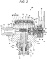
- FIG. 2 is a longitudinal cross-sectional view (part 1) of the high-pressure fuel supply pump 100 as viewed in cross section orthogonal to the horizontal direction.
- FIG. 3 is a longitudinal cross-sectional view (part 2) of the high-pressure fuel supply pump 100 as viewed in cross section orthogonal to the horizontal direction.
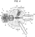
- FIG. 4 is a horizontal-direction cross-sectional view of the high-pressure fuel supply pump 100 as viewed in cross section orthogonal to a vertical direction of the high-pressure fuel supply pump 100.
- FIG. 5 is a perspective cross-sectional view with a part broken away of the high-pressure fuel supply pump 100.
- a pump body 1 of the high-pressure fuel supply pump 100 is formed in a substantially circular columnar shape. As illustrated in FIG. 2 and FIG. 3 , the pump body 1 includes a first chamber 1a, a second chamber 1b, a third chamber 1c, and an intake passage 1d.
- the first chamber 1a is a circular columnar space portion formed in the pump body 1.
- a center line 1A of the first chamber 1a agrees with a center line of the pump body 1.
- One end portion of the plunger 2 is inserted into the first chamber 1a.
- the plunger 2 reciprocates in the first chamber 1a.
- the first chamber 1a and one end of the plunger 2 form a pressurizing chamber 11.
- the second chamber 1b is a circular columnar space portion formed in the pump body 1, and a center line of the second chamber 1b is orthogonal to the center line of the pump body 1 (first chamber 1a).
- the relief valve mechanism 4 is disposed in the second chamber 1b. Therefore, the second chamber 1b illustrates a specific example of a relief chamber according to the present invention.
- a diameter of the second chamber 1b is smaller than a diameter of the first chamber 1a.
- a diameter of the communication hole 1e is equal to the diameter of the first chamber 1a.
- the communication hole 1e is formed by extending one end of the first chamber 1a.
- a diameter of the communication hole 1e is larger than an outer diameter of the plunger 2.
- a center line 1A of the communication hole 1e agrees with the center line of the pump body 1.
- the center line of the communication hole 1e is orthogonal to the center line of the second chamber 1b. As illustrated in FIG. 3 , a diameter of the communication hole 1e is larger than a diameter of the second chamber 1b.
- a third chamber 1c is a circular columnar space portion formed in the pump body 1.
- the third chamber 1c is continuously formed with the other end of the first chamber 1a.
- a center line 1A of the third chamber 1c agrees with the center line 1A of the first chamber 1a and the center line of the pump body 1.
- a diameter of the third chamber 1c is larger than the diameter of the first chamber 1a.
- a cylinder 6 that guides the reciprocation of the plunger 2 is disposed in the third chamber 1c.
- the cylinder 6 is formed in a cylindrical shape, and an outer peripheral side of the cylinder 6 is press-fitted into the third chamber 1c of the pump body 1. One end of the cylinder 6 is brought into contact with a top surface of the third chamber 1c (step portion formed between the first chamber 1a and the third chamber 1c).
- the plunger 2 is in brought into contact with an inner peripheral surface of the cylinder 6 in a slidable manner. The plunger 2 is guided by the cylinder 6 and reciprocates in the axial direction.
- An O-ring 93 that illustrates a specific example of a seat member is interposed between a fuel pump mounting portion (not shown) and the pump body 1.
- the O-ring 93 prevents engine oil from leaking to the outside of an engine (internal combustion engine) through between the fuel pump mounting portion and the pump body 1.
- a tappet (not illustrated) is mounted on a lower end of the plunger 2.
- the tappet converts a rotational motion of a cam mounted on a cam shaft of the engine into a vertical motion and transmits the vertical motion to the plunger 2.
- the plunger 2 is biased toward a cam (not illustrated) side by a spring 16 by way of a retainer 15.
- the tappet reciprocates due to the rotation of the cam.
- the plunger 2 reciprocates together with the tappet.
- a volume of the pressurizing chamber 11 changes.
- a seal holder 17 is disposed between the cylinder 6 and the retainer 15.
- the seal holder 17 is formed in a cylindrical shape so as to allow the insertion of the plunger 2 into the seal holder 17.
- An auxiliary chamber 17a is formed in an upper end portion of the seal holder 17 on a cylinder 6 side.
- the seal holder 17 holds a plunger seal 18 at a lower end portion of the seal holder 17 on a retainer 15 side.
- the plunger seal 18 is brought into contact with an outer periphery of the plunger 2 in a slidable manner.
- the plunger seal 18 seals fuel in the auxiliary chamber 17a. With such a configuration, when the plunger 2 reciprocates, it is possible to prevent the fuel in the auxiliary chamber 17a from flowing into the engine.
- the plunger seal 18 also prevents lubricating oil (including engine oil) that lubricates sliding portions in the engine from flowing into the pump body 1.
- the plunger 2 reciprocates in the vertical direction.
- the volume of the pressurizing chamber 11 is increased, and when the plunger 2 ascends, the volume of the pressurizing chamber 11 is decreased. That is, the plunger 2 is disposed so as to reciprocate in directions of enlarging and reducing the volume of the pressurizing chamber 11.
- the plunger 2 has a large diameter portion 2a and a small diameter portion 2b.
- the large diameter portion 2a and the small diameter portion 2b are positioned in the auxiliary chamber 17a. Accordingly, the volume in the auxiliary chamber 17a is increased or decreased by the reciprocation of the plunger 2.
- the auxiliary chamber 17a communicates with a low-pressure fuel chamber 10 through a fuel passage 10c (see FIG. 3 ).
- a fuel passage 10c see FIG. 3 .
- an intake joint 5 is mounted on a side surface portion of the pump body 1.
- the intake joint 5 is connected to the low-pressure pipe 104 through which fuel supplied from the fuel tank 103 (see FIG. 1 ) passes.
- the fuel in the fuel tank 103 is supplied from the intake joint 5 to the inside of the pump body 1.
- the intake joint 5 includes: the low-pressure fuel intake port 51 that is connected to the low-pressure pipe 104; and an intake flow passage 52 that communicates with the low-pressure fuel intake port 51.
- the fuel that has passed through the intake flow passage 52 passes through an intake filter 53 disposed in the pump body 1 and is supplied to the low-pressure fuel chamber 10.
- the intake filter 53 removes foreign substances present in the fuel thus preventing the foreign substances from entering the high-pressure fuel supply pump 100.
- the low-pressure fuel chamber 10 is formed on an upper portion of the pump body 1 of the high-pressure fuel supply pump 100.
- the low-pressure fuel chamber 10 includes a low-pressure fuel flow passage 10a and an intake passage 10b (see FIG. 2 ).
- the low-pressure fuel flow passage 10a includes the pressure pulsation reduction mechanism 9.
- the pressure pulsation reduction mechanism 9 reduces the propagation of the pressure pulsation generated in the high-pressure fuel supply pump 100 to the low-pressure pipe 104.
- the pressure pulsation reduction mechanism 9 is formed of a metal diaphragm damper in which an inert gas such as argon is filled.
- the metal diaphragm damper is formed by laminating outer peripheries of two corrugated disk-shaped metal plates to each other.
- the metal diaphragm damper of the pressure pulsation reduction mechanism 9 expands and contracts so as to absorb or reduce the pressure pulsation.
- the intake passage 10b communicates with the intake port 31b (see FIG. 2 ) of the electromagnetic intake valve mechanism 3, and fuel that passes through the low-pressure fuel flow passage 10a reaches the intake port 31b of the electromagnetic intake valve mechanism 3 through the intake passage 10b.
- the electromagnetic intake valve mechanism 3 is inserted into a lateral hole formed in the pump body 1.
- the electromagnetic intake valve mechanism 3 includes: an intake valve seat 31 that is press-fitted into a lateral hole formed in the pump body 1; a valve element 32; a rod 33; a rod biasing spring 34; an electromagnetic coil 35; and an anchor 36.
- the intake valve seat 31 is formed in a cylindrical shape, and a seating portion 31a is formed on an inner peripheral portion.
- An intake port 31b that reaches an inner peripheral portion from an outer peripheral portion is also formed in the intake valve seat 31.
- the intake port 31b communicates with the intake passage 10b in the low-pressure fuel chamber 10 described above.
- a stopper 37 that faces the seating portion 31a of the intake valve seat 31 is disposed in the lateral hole formed in the pump body 1.
- the valve element 32 is disposed between the stopper 37 and the seating portion 31a.
- a valve biasing spring 38 is interposed between the stopper 37 and the valve element 32. The valve biasing spring 38 biases the valve element 32 toward a seating portion 31a side.
- valve element 32 When the valve element 32 is brought into contact with the seating portion 31a, the valve element 32 closes a communicating portion formed between the intake port 31b and the pressurizing chamber 11. As a result, the electromagnetic intake valve mechanism 3 assumes a valve closing state. On the other hand, when the valve element 32 is brought into contact with the stopper 37, the valve element 32 opens the communicating portion formed between the intake port 31b and the pressurizing chamber 11. As a result, the electromagnetic intake valve mechanism 3 assumes a valve open state.
- the rod 33 penetrates a cylinder hole of the intake valve seat 31. One end of the rod 33 is brought into contact with the valve element 32.
- the rod biasing spring 34 biases the valve element 32 in the valve opening direction which is a stopper 37 side by way of the rod 33.
- One end of the rod biasing spring 34 engages with the other end of the rod 33.
- the other end of the rod biasing spring 34 engages with a magnetic core 39 disposed so as to surround the rod biasing spring 34.
- the anchor 36 faces an end surface of the magnetic core 39.
- the anchor 36 also engages with a flange mounted on an intermediate portion of the rod 33.
- the electromagnetic coil 35 is disposed around the whole circumference of the magnetic core 39.
- a terminal member 40 is electrically connected to the electromagnetic coil 35, and a current flows to the electromagnetic coil 35 through the terminal member 40.
- the rod 33 In a non-energized state where a current is not supplied to the electromagnetic coil 35, the rod 33 is biased in a valve opening direction by a biasing force of the rod biasing spring 34. As a result, the rod 33 pushes the valve element 32 in the valve opening direction. As a result, the valve element 32 is separated from the seating portion 31a and is brought into contact with the stopper 37 and hence, the electromagnetic intake valve mechanism 3 assumes a valve open state. That is, the electromagnetic intake valve mechanism 3 is a normally open type valve that opens in a non-energized state.
- the anchor 36 When a current is supplied to the electromagnetic coil 35, the anchor 36 is attracted in a valve closing direction by a magnetic attractive force of the magnetic core 39. As a result, the anchor 36 moves against a biasing force of the rod biasing spring 34, and is brought into contact with the magnetic core 39. When the anchor 36 moves in the valve closing direction on a magnetic core 39 side, the rod 33 moves together with the anchor 36. As a result, the valve element 32 is released from a biasing force in the valve opening direction, and moves in the valve closing direction by a biasing force of the valve biasing spring 38.
- the discharge valve mechanism 8 is connected to an outlet side (downstream side) of the pressurizing chamber 11.
- the discharge valve mechanism 8 includes: a discharge valve seat 81 that communicates with the pressurizing chamber 11, a valve element 82 that is brought into contact with and is separable from the discharge valve seat 81; a discharge valve spring 83 that biases the valve element 82 toward a discharge valve seat 81 side; and a discharge valve stopper 84 that determines a stroke (moving distance) of the valve element 82.
- the discharge valve seat 81 is formed in a substantially cylindrical shape.
- the discharge valve seat 81 has a seat passage 8a which is a shaft hole.
- the seat passage 8a forms a passage on a pressurizing chamber 11 side in the discharge valve mechanism 8.
- a discharge valve inlet passage 1f that allows the pressurizing chamber 11 and the seat passage 8a to communicate with each other is formed in the pump body 1.
- the discharge valve inlet passage 1f also communicates with the second chamber 1b (relief chamber) besides the pressurizing chamber 11.
- the valve element 82 faces an end surface of the discharge valve seat 81 on a side opposite to a pressurizing chamber 11 side.
- the valve element 82 is biased toward a discharge valve seat 81 side and is pressed against the discharge valve seat 81 by the discharge valve spring 83.
- the valve element 82 is separated from the discharge valve seat 81, fuel in the pressurizing chamber 11 can pass through between the valve element 82 and the discharge valve seat 81.
- the discharge valve mechanism 8 assumes a valve open state.
- the discharge valve mechanism 8 includes a plug 85 that blocks leakage of fuel to the outside.
- the discharge valve stopper 84 is press-fitted into the plug 85.
- the plug 85 is joined to the pump body 1 by welding at a welded portion 86.
- the discharge valve mechanism 8 communicates with a discharge chamber 87 that is opened and closed by the valve element 82.
- the discharge chamber 87 is formed in the pump body 1.
- a lateral hole that communicates with the second chamber 1b (see FIG. 2 ) is formed in the pump body 1, and a discharge joint 12 is inserted into the lateral hole.
- the discharge joint 12 includes: the above discharge passage 12a that communicates with the lateral hole formed in the pump body 1 and the discharge chamber 87; and a fuel discharge port 12b that forms one end of the discharge passage 12a.
- the fuel discharge port 12b of the discharge joint 12 communicates with the common rail 106.
- the discharge joint 12 is fixed to the pump body 1 by welding by a welded portion 12c.
- the valve element 82 In a state where there is no difference in fuel pressure (fuel differential pressure) between the pressurizing chamber 11 and the discharge chamber 87, the valve element 82 is brought into pressure contact with the discharge valve seat 81 by a biasing force of the discharge valve spring 83. As a result, the discharge valve mechanism 8 assumes a valve closing state. When the fuel pressure in the pressurizing chamber 11 becomes larger than the fuel pressure in the discharge chamber 87, the valve element 82 moves against the biasing force of the discharge valve spring 83. As a result, the discharge valve mechanism 8 assumes a valve open state.
- the moving direction of the valve element 82 in the discharge valve mechanism 8 is orthogonal to the direction that the plunger 2 reciprocates.
- the direction that the plunger 2 reciprocates corresponds to the first direction according to the present invention.
- the moving direction of the valve element 82 in the discharge valve mechanism 8 corresponds to the third direction according to the present invention.
- the discharge valve mechanism 8 When the discharge valve mechanism 8 is brought into a valve closed state, the (high-pressure) fuel in the pressurizing chamber 11 passes through the discharge valve mechanism 8, and reaches the discharge chamber 87. Then, the fuel that has reached the discharge chamber 87 is discharged to the common rail 106 (see FIG. 1 ) through the fuel discharge port 12b of the discharge joint 12.
- the discharge valve mechanism 8 functions as a check valve that restricts the flowing direction of the fuel.
- the relief valve mechanism 4 illustrated in FIG. 2 is operated so as to return the fuel in the discharge passage 12a to the pressurizing chamber 11.
- the relief valve mechanism 4 is disposed at the position higher than the discharge valve mechanism 8 (see FIG. 5 ) in the direction (vertical direction) that the plunger 2 reciprocates.
- the relief valve mechanism 4 includes a relief spring 41, a relief valve holder 42, a valve element 43, and a seat member 44.
- the relief valve mechanism 4 is inserted into the pump body 1 from the discharge joint 12 and is disposed in the second chamber 1b.
- One end portion of the relief spring 41 is brought into contact with the pump body 1 (one end of the second chamber 1b), and the other end portion of the relief valve 41 is brought into contact with the relief valve holder 42.
- the relief valve holder 42 engages with the valve element 43.
- a biasing force of the relief spring 41 acts on the valve element 43 by way of the relief valve holder 42.
- the valve element 43 is pressed by the biasing force of the relief spring 41 so that the valve element 43 closes the fuel passage in the seat member 44.
- the moving direction of the valve element 43 (relief valve holder 42) is orthogonal to the direction that the plunger 2 reciprocates.
- the center line of the relief valve mechanism 4 (the center line of the relief valve holder 42) is orthogonal to the center line of the plunger 2.
- the moving direction of the valve element 43 in the relief valve mechanism 4 corresponds to the second direction according to the present invention.
- the seat member 44 has a fuel passage that faces the valve element 43. A portion of the fuel passage formed in the seat member 44 on a side opposite to the valve element 43 communicates with the discharge passage 12a. The valve element 43 is brought into contact (close contact) with the seat member 44 so as to close the fuel passage. With such a configuration, the movement of fuel between the pressurizing chamber 11 (upstream side) and the seat member 44 (downstream side) is blocked.
- the moving direction of the valve element 43 (see FIG. 5 ) in the relief valve mechanism 4 differs from the moving direction of the valve element 82 in the discharge valve mechanism 8. That is, as viewed from the direction that the plunger 2 reciprocates, the moving direction of the valve element 43 in the relief valve mechanism 4 intersects with the moving direction of the valve element 82 in the discharge valve mechanism 8.
- the discharge valve mechanism 8 and the relief valve mechanism 4 can be disposed at positions that do not overlap with each other in the direction that the plunger 2 reciprocates. Accordingly, downsizing of the pump body 1 can be realized by effectively making use of the space in the pump body 1.
- the moving direction of the valve element 82 in the discharge valve mechanism 8 is the first radial direction of the pump body 1
- the moving direction of the valve element 43 in the relief valve mechanism 4 is the second radial direction that differs from the first radial direction of the pump body 1.
- An angle at which the first radial direction and the second radial direction illustrated in FIG. 4 intersect with each other is smaller than 90 degrees. However, the angle at which the first radial direction and the second radial direction intersect with each other may be approximately 90 degrees.
- the discharge valve mechanism 8 and the relief valve mechanism 4 are disposed in a direction where the moving direction of the valve element 82 and the moving direction of the valve element 43 intersect with each other.
- the relief valve mechanism 4 is disposed at the position that overlaps with the pressurizing chamber 11 in the reciprocating direction of the plunger 2 and the moving direction of the valve element 43 of the relief valve mechanism 4.
- the volumetric efficiency is a ratio of a discharge amount of fuel discharged from the discharge valve mechanism 8 with respect to a moving distance from a bottom dead center of the plunger 2 where a volume of the pressurizing chamber 11 becomes the largest to a top dead center of the plunger 2 where the volume of the pressurizing chamber 11 becomes the smallest.
- the bottom dead center of the plunger 2 is the position where the plunger 2 is at the lowermost end (cam side of the engine).
- the top dead center of the plunger is the position where the plunger 2 is at the uppermost end.
- the relief valve mechanism 4 overlaps with the entire region of the pressurizing chamber 11 parallel to the moving direction of the valve element 43 of the relief valve mechanism 4. With such a configuration, fuel that passes through the relief valve mechanism 4 can be efficiently returned to the pressurizing chamber 11.
- the discharge valve mechanism 8 is disposed at the position that overlaps with the relief valve mechanism 4 as viewed in the moving direction of the valve element 82 of the discharge valve mechanism 8.
- a lower end L1 of the second chamber 1b (relief chamber) in which the relief valve mechanism 4 is disposed is arranged at a position closer to the plunger 2 in the reciprocating direction of the plunger 2 than the upper end L2 of the seat passage 8a in the discharge valve mechanism 8. Further, an upper end of the seat passage 8a in the discharge valve mechanism 8 is higher than an upper surface of the plunger 2 (see FIG. 6 ) that is positioned at the top dead center.
- an upper end of the relief valve mechanism 4 is disposed at a position remoter from the plunger 2 than an upper end of the discharge valve mechanism 8 in the reciprocating direction of the plunger 2. Further, as illustrated in FIG. 3 , the relief valve mechanism 4 is disposed at the position that overlaps with the discharge valve mechanism 8 as viewed in the horizontal direction orthogonal to the reciprocating direction of the plunger 2. With such a configuration, a length of the pump body 1 in the direction that the plunger 2 reciprocates (a length of the pump body 1 in the axial direction) can be shortened. Accordingly, downsizing of the pump body 1 can be realized.
- the first chamber 1a and the second chamber 1b formed in the pump body 1 partially overlap with each other.
- the discharge valve inlet passage 8a directly communicates with the first chamber 1a and the second chamber 1b.
- the discharge valve inlet passage communicates only with the first chamber.
- the plunger that is positioned at the top dead center blocks the discharge valve inlet passage, a sufficient amount of fuel does not flow into the discharge valve mechanism. Therefore, conventionally, it is necessary to secure a space in the pump body in the direction that the plunger reciprocates, and to dispose the discharge valve inlet passage at the position where the discharge valve inlet passage is not closed by the plunger located at the top dead center.
- the discharge valve inlet passage 8a communicates with not only the first chamber 1a but also the second chamber 1b. Accordingly, even if a space is not secured in the direction that the plunger 2 reciprocates in the pump body 1, it is possible to allow a sufficient amount of fuel to flow into the discharge valve mechanism.
- the configuration of the passage that communicates with the first chamber 1a can be simplified and hence, a working cost can be reduced.
- the discharge valve inlet passage 8a can be formed with a large diameter, a pressure loss is reduced. Accordingly, this configuration can also contribute to the enhancement of performance.
- the diameter of the communication hole 1e is equal to the diameter of the first chamber 1a. Therefore, the working of the communication hole 1e can be performed easily, and the protrusions (burrs) can be easily removed.
- the productivity of the pump body 1 and the high-pressure fuel supply pump 100 can be improved, and a cost can be reduced.
- the hole (passage) can be easily worked and, at the same time, the burrs can be easily removed. As a result, the quality of the high-pressure fuel supply pump 100 can be improved.
- the diameter of the communication hole 1e is equal to the diameter of the first chamber 1a. Accordingly, it is possible to allow the fuel to easily flow from the relief valve 4 into the pressurizing chamber 11 and hence, the relief performance can be improved. Furthermore, the relief valve is directly incorporated in the second chamber 1b formed in the pump body 1. Accordingly, a housing (seat member) for housing components that form the relief valve can be omitted and hence, the number of components can be reduced whereby a cost can be reduced.
- the electromagnetic intake valve mechanism 3 when the electromagnetic intake valve mechanism 3 is closed during the rising stroke, the fuel sucked into the pressurizing chamber 11 is pressurized during the intake stroke. As a result, the discharge valve mechanism 8 is opened, and the fuel in the pressurizing chamber 11 is discharged to a common rail 106 side. On the other hand, when the electromagnetic intake valve mechanism 3 is opened during the rising stroke, the fuel in the pressurizing chamber 11 is pushed back toward an intake passage 1d side. Therefore, the fuel in the pressurizing chamber 11 is not discharged to the common rail 106 side. In this manner, the discharge of the fuel by the high-pressure fuel supply pump 100 is operated by opening and closing the electromagnetic intake valve mechanism 3. The opening and closing of the electromagnetic intake valve mechanism 3 is controlled by the ECU 101.
- a fluid differential pressure between the intake port 31b and the pressurizing chamber 11 (hereinafter, referred to as a "fluid differential pressure before and after the valve element 32") is decreased.
- the biasing force of the rod biasing spring 34 becomes larger than the fluid differential pressure before and after the valve element 32, the rod 33 moves in the valve opening direction. Then, the valve element 32 is separated from the seating portion 31a of the intake valve seat 31, and the electromagnetic intake valve mechanism 3 assumes a valve open state.
- valve open state fuel in the intake port 31b passes between the valve element 32 and the seating portion 31a, and flows into the pressurizing chamber 11 after passing through a plurality of fuel passing holes (not illustrated) formed in the stopper 37.
- a valve open state of the electromagnetic intake valve mechanism 3 the valve element 32 is brought into contact with the stopper 37 and hence, the position of the valve element 32 in the valve opening direction is restricted.
- a gap existing between the valve element 32 and the seating portion 31a in a valve open state of the electromagnetic intake valve mechanism 3 is a movable range of the valve element 32. This movable range is referred to as a valve open stroke.
- the process proceeds to the rising stroke.
- the electromagnetic coil 35 remains in a non-energized state and hence, a magnetic attractive force does not act between the anchor 36 and the magnetic core 39.
- a biasing force in the valve opening direction corresponding to a difference in biasing force between the rod biasing spring 34 and the valve biasing spring 38, and a pressing force in the valve closing direction by a fluid force generated when the fuel flows back from the pressurizing chamber 11 to the low-pressure fuel flow passage 10a act.
- the difference between the biasing force of the rod biasing spring 34 and the biasing force of the valve biasing spring 38 is set larger than the fluid force.
- the volume of the pressurizing chamber 11 decreases as the plunger 2 ascends. Therefore, the fuel sucked into the pressurizing chamber 11 passes again between the valve element 32 and the seating portion 31a and is returned to the intake port 31b. Accordingly, there is no possibility that the pressure in the pressurizing chamber 11 is increased. This stroke is referred to as a return stroke.
- valve element 32 When the anchor 36 (rod 33) moves in the valve closing direction, the valve element 32 is released from a biasing force in the valve opening direction. As a result, the valve element 32 moves in the valve closing direction by a biasing force of the valve biasing spring 38 and a fluid force generated by the fuel that flows into the intake passage 10b. Then, when the valve element 32 is brought into contact with the seating portion 31a of the intake valve seat 31 (when the valve element 32 is seated on the seating portion 31a), the electromagnetic intake valve mechanism 3 assumes a valve closing state.
- the fuel in the pressurizing chamber 11 is pressurized as the plunger 2 ascends.
- the fuel in the pressurizing chamber 11 reaches or exceeds a predetermined pressure
- the fuel passes through the discharge valve mechanism 8 and is discharged to the common rail 106 (see FIG. 1 ).
- This stroke is referred to as a discharge stroke. That is, the upward stroke from the bottom dead center to the top dead center of the plunger 2 includes a return stroke and a discharge stroke.
- the timing of energizing the electromagnetic coil 35 is made earlier, the ratio of the return stroke during the rising stroke becomes smaller, and the ratio of the discharge stroke becomes larger. As a result, an amount of fuel returned to the intake passage 10b is decreased, and an amount of fuel discharged at a high pressure is increased. On the other hand, if the timing of energizing the electromagnetic coil 35 is delayed, a ratio of the return stroke during the rising stroke is increased, and a ratio of the discharge stroke is decreased. As a result, an amount of fuel that is returned to the intake passage 10b is increased, and an amount of fuel discharged at a high pressure is decreased. By controlling the timing of energizing the electromagnetic coil 35, an amount of fuel to be discharged at a high pressure can be controlled to an amount that an engine (internal combustion engine) requires.
- a high-pressure fuel supply pump according to a second embodiment of the present invention is described hereinafter.
- a point that makes the high-pressure fuel supply pump according to the second embodiment differ from the high-pressure fuel supply pump 100 according to the first embodiment is the position at which a discharge valve mechanism 8 is disposed. Therefore, in the description made hereinafter, the position of the discharge valve mechanism 8 is described, and the description of the configurations and the manner of operation common to the high-pressure fuel supply pump 100 according to the first embodiment is omitted.
- FIG. 6 is a longitudinal cross-sectional view of the high-pressure fuel supply pump according to the second embodiment as viewed in cross section orthogonal to the horizontal direction.
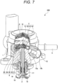
- FIG. 7 is a perspective cross-sectional view with a part broken away of the high-pressure fuel supply pump according to the second embodiment.
- the high-pressure fuel supply pump 200 according to the second embodiment has the same configuration as the high-pressure fuel supply pump 100 according to the first embodiment.
- the moving direction of a valve element 43 in a relief valve mechanism 4 differs from the moving direction of a valve element 82 in a discharge valve mechanism 8. That is, as viewed from the direction that the plunger 2 reciprocates, the moving direction of the valve element 43 in the relief valve mechanism 4 intersects with the moving direction of the valve element 82 in the discharge valve mechanism 8.
- the relief valve mechanism 4 is disposed at the position that overlaps with the pressurizing chamber 11 in the reciprocating direction of the plunger 2 and the moving direction of the valve element 43 of the relief valve mechanism 4.
- the discharge valve mechanism 8 is disposed at the position that overlaps with the relief valve mechanism 4 as viewed in the moving direction of the valve element 82 of the discharge valve mechanism 8.
- a lower end L1 of the second chamber 1b (relief chamber) in which the relief valve mechanism 4 is disposed is arranged at a position closer to the plunger 2 in the reciprocating direction of the plunger 2 than the upper end L2 of the seat passage 8a in the discharge valve mechanism 8. Further, an upper end of the seat passage 8a in the discharge valve mechanism 8 is higher than an upper surface of the plunger 2 (see FIG. 6 ) that is positioned at the top dead center.
- an upper end of the relief valve mechanism 4 and an upper end of the discharge valve mechanism 8 are set substantially at the same height in the reciprocating direction of the plunger 2. Further, as illustrated in FIG. 6 , the relief valve mechanism 4 is disposed at the position that overlaps with the discharge valve mechanism 8 as viewed in the horizontal direction orthogonal to the reciprocating direction of the plunger 2.
- the discharge valve mechanism 8 overlaps with an entire region of the relief valve mechanism 4 in a direction that the plunger 2 reciprocates.
- the high-pressure fuel supply pump (fuel pump) according to the above-described embodiments includes: the pump body 1 (pump body) that has the pressurizing chamber 11 (pressurizing chamber) and the discharge chamber 87 (discharge chamber); the plunger 2 (plunger) that reciprocates in the pressurizing chamber 11; and the discharge valve mechanism 8 (discharge valve mechanism) that discharges the fuel in the pressurizing chamber 11 to the discharge chamber 87.
- the high-pressure fuel supply pump includes a relief valve mechanism 4 (relief valve mechanism) that opens when a difference between a pressure of fuel in the discharge chamber 87 and a pressure of fuel in the pressurizing chamber 11 exceeds a predetermined value, and returns the fuel in the discharge chamber 87 to the pressurizing chamber 11.
- the discharge valve mechanism 8 and the relief valve mechanism 4 are disposed in a direction where the moving directions of the respective valve elements 82, 43 (valves) intersect with each other.
- the relief valve mechanism 4 is disposed at the position that overlaps with the pressurizing chamber 11 in the first direction and in the second direction that is the moving direction of the valve element 43 of the relief valve mechanism 4.
- the discharge valve mechanism 8 and the relief valve mechanism 4 can be disposed at positions that do not overlap with each other in the first direction.
- the space in the pump body 1 can be effectively used, and the downsizing of the pump body 1 can be realized.
- a dead volume of the pressurizing chamber 11 can be reduced compared with a case where a passage for making the relief valve mechanism 4 and the pressurizing chamber 11 communicate with each other is provided. Accordingly, the volumetric efficiency of the pressurizing chamber 11 can be improved.
- the discharge valve mechanism 8 is disposed at the position that overlaps with the relief valve mechanism 4 (relief valve mechanism) as viewed from the third direction that is the moving direction of the valve element 82 (valve) in the discharge valve mechanism 8 (discharge valve mechanism).
- the lower end L1 of the second chamber 1b (relief chamber) in which the relief valve mechanism 4 (relief valve mechanism) is disposed is disposed at the position closer to the plunger 2 (plunger) in the first direction than the upper end L2 of the seat passage 8a (passage on the pressurizing chamber side) in the discharge valve mechanism 8 (discharge valve mechanism).
- the discharge valve mechanism 8 discharge valve mechanism
- the relief valve mechanism 4 relieve valve mechanism
- the discharge valve mechanism 8 and the relief valve mechanism 4 can be disposed such that the moving directions of the respective valve elements 82, 43 (valves) are disposed approximately orthogonal to each other as viewed from the first direction.
- the discharge valve mechanism 8 and the relief valve mechanism 4 can be disposed in a spaced-apart manner from each other thus preventing the interference between the discharge valve mechanism 8 and the relief valve mechanism 4
- the space in the pump body 1 can be effectively used and hence, the downsizing of the pump body 1 can be realized.
- the relief valve mechanism 4 (relief valve mechanism) is disposed at the position that overlaps with the discharge valve mechanism 8 ( discharge valve mechanism) as viewed from the horizontal direction orthogonal to the first direction.
- the discharge valve mechanism 8 overlaps with the entire region of the relief valve mechanism 4 (relief valve mechanism) in the first direction as viewed from the second direction.
- a length of the pump body 1 in the first direction (a length of the pump body 1 in the axial direction) can be more shortened than the length of the pump body 1 in the first embodiment. Accordingly, downsizing of the pump body 1 can be realized.
- the upper end of the relief valve mechanism 4 (relief valve mechanism) is disposed remoter from the plunger (2) (plunger) than the upper end of the discharge valve mechanism 8 (discharge valve mechanism) in the first direction.
- the discharge valve mechanism 8 is disposed closer to the plunger 2 side in the first direction than the relief valve mechanism 4. It is necessary to set the relief valve mechanism 4 at the position higher than the top dead center of the plunger 2 in order to avoid the interference between the relief valve mechanism 4 and the plunger 2. Therefore, by disposing the discharge valve mechanism 8 on the plunger 2 side in the first direction than the relief valve mechanism 4, it is possible to suppress the pump body 1 from becoming elongated in the first direction.
- the relief valve mechanism 4 overlaps with the entire region of the pressurizing chamber 11 (pressurizing chamber) in the second direction as viewed from the direction orthogonal to the first direction and the second direction. With such a configuration, fuel that passes through the relief valve mechanism 4 can be efficiently returned to the pressurizing chamber 11.
- the upper end of the seat passage 8a (passage on the pressurizing chamber side) in the discharge valve mechanism 8 is higher than the upper surface of the plunger 2 positioned at the top dead center.
- the moving direction of the valve element 32 in the electromagnetic intake valve mechanism 3 is set to the second radial direction that is equal to the moving direction of the valve element 43 in the relief valve mechanism 4 (see FIG. 2 ).
- the moving direction of the valve element in the relief valve according to the present invention may be different from the moving direction of the valve element in the electromagnetic intake valve.
- the moving direction of the valve element in the relief valve, the moving direction of the valve element in the electromagnetic intake valve, and the moving direction of the valve element in the discharge valve may all be set different from each other.
- valve elements 82 of the discharge valve mechanism 8 and the valve element 43 of the relief valve mechanism 4 move in directions perpendicular to the direction (first direction) that the plunger 2 reciprocates.
- the directions that the valve of the discharge valve mechanism and the valve of the relief valve mechanism according to the present invention move may be inclined with respect to the directions perpendicular to the direction (first direction) that the plunger 2 reciprocates. That is, the discharge valve mechanism and the relief valve mechanism may be obliquely connected to the pressurizing chamber.
Landscapes
- Engineering & Computer Science (AREA)
- Mechanical Engineering (AREA)
- General Engineering & Computer Science (AREA)
- Chemical & Material Sciences (AREA)
- Combustion & Propulsion (AREA)
- Fuel-Injection Apparatus (AREA)
- Details Of Reciprocating Pumps (AREA)
Abstract
Description
- The present invention relates to a fuel pump that supplies fuel to an engine after pressurizing the fuel to a high pressure.
- As a fuel pump, there has been known a fuel pump described in
PTL 1, for example. The high-pressure fuel supply pump described inPTL 1 includes a housing, an intake valve, a discharge valve, and a relief valve. - The housing has a cylinder in which a stepped cylindrical space is formed where a cylinder liner that slidably holds a plunger is accommodated and a pressurizing chamber is formed The intake valve is opened in a state where a current is not supplied to an electromagnetic solenoid, and when the current is supplied to the electromagnetic solenoid, the intake valve is opened so that a fuel is sucked into the pressurizing chamber.
- The discharge valve is assembled to a discharge valve accommodating portion of the housing, and the discharge valve accommodating portion communicates with a pressurizing chamber through a fuel discharge hole. The high-pressure fuel obtained by pressurizing fuel in the pressurizing chamber is supplied to the discharge valve. The discharge valve is opened when the pressure of the supplied fuel becomes equal to or higher than a predetermined pressure, and the fuel that has passed through the discharge valve is pressure-fed to an accumulator.
- A relief valve is assembled in a relief valve accommodating portion of the housing. The relief valve accommodating portion communicates with a high-pressure region on a downstream side of the discharge valve, and communicates with the pressurizing chamber through a communication passage. The relief valve is opened when the pressure of the fuel in the high-pressure region becomes equal to or higher than a specific pressure, and returns the high-pressure fuel to the pressurizing chamber.
- PTL 1:
JP 2018-523778 A - However, in the high-pressure fuel supply pump described in
PTL 1, a communication passage for making the discharge valve and the pressurizing chamber communicate with each other and a communication passage for making the relief valve and the pressurizing chamber communicate with each other are independently provided. As a result, in the high-pressure fuel supply pump described inPTL 1, a dead volume when the pressurizing chamber is filled with the fuel is increased and hence, volumetric efficiency of the pump is lowered. - The present invention has been made in view of the above-mentioned problems, and it is an object of the present invention to provide a fuel pump capable of enhancing volumetric efficiency.
- In order to solve the above problems and to achieve the object of the present invention, a fuel pump of the present invention includes: a pump body in which a pressurizing chamber is formed; a plunger that reciprocates in the pressurizing chamber; a discharge valve mechanism that discharges fuel in the pressurizing chamber to a discharge chamber; and a relief valve mechanism. The relief valve mechanism opens when a difference between a pressure of the fuel in the discharge chamber and a pressure of the fuel in the pressurizing chamber exceeds a set value, and returns the fuel in the discharge chamber to the pressurizing chamber. As viewed from an axial direction of the plunger, the discharge valve mechanism and the relief valve mechanism are disposed in a direction where moving directions of the valves intersect with each other. The relief valve mechanism is disposed at a position where the relief valve overlaps with the pressurizing chamber in the axial direction of the plunger.
- According to the fuel pump having the above configuration, volumetric efficiency can be improved.
- Problems, configurations, and advantageous effects other than those described above will be clarified by the following description of embodiments.
-
- [
FIG. 1] FIG. 1 is a view illustrating an overall configuration of a fuel supply system that uses a high-pressure fuel supply pump according to a first embodiment of the present invention. - [
FIG. 2] FIG. 2 is a longitudinal cross-sectional view (part 1) of the high-pressure fuel supply pump according to the first embodiment of the present invention. - [
FIG. 3] FIG. 3 is a longitudinal cross-sectional view (part 2) of the high-pressure fuel supply pump according to the first embodiment of the present invention. - [
FIG. 4] FIG. 4 is a horizontal cross-sectional view of the high-pressure fuel supply pump according to the first embodiment of the present invention as viewed from above. - [
FIG. 5] FIG. 5 is a perspective cross-sectional view with a part broken away of the high-pressure fuel supply pump according to the first embodiment of the present invention. - [
FIG. 6] FIG. 6 is a longitudinal cross-sectional view of a high-pressure fuel supply pump according to a second embodiment of the present invention. - [
FIG. 7] FIG. 7 is a perspective cross-sectional view with a part broken away of the high-pressure fuel supply pump according to the second embodiment of the present invention. - A high-pressure fuel supply pump according to a first embodiment of the present invention is described hereinafter. In the respective drawings, the identical members are denoted by the same reference numerals.
- A fuel supply system that uses a high-pressure fuel supply pump (fuel pump) according to a first embodiment will be described with reference to
FIG. 1 . -
FIG. 1 is a view illustrating an overall configuration of the fuel supply system that uses the high-pressure fuel supply pump according to the first embodiment of the present invention. - As illustrated in
FIG. 1 , the fuel supply system includes a high-pressure fuel supply pump (fuel pump) 100, an engine control unit (ECU) 101, afuel tank 103, acommon rail 106, and a plurality ofinjectors 107. Components of the high-pressurefuel supply pump 100 are integrally incorporated in thepump body 1. - Fuel in the
fuel tank 103 is pumped up by afeed pump 102 that is driven in response to a signal from the ECU 101. The pumped-up fuel is pressurized to an appropriate pressure by a pressure regulator (not illustrated) and is supplied to a low-pressurefuel intake port 51 of the high-pressurefuel supply pump 100 through a low-pressure pipe 104. - The high-pressure
fuel supply pump 100 pressurizes the fuel supplied from thefuel tank 103, and pressure-feeds the fuel to thecommon rail 106. A plurality ofinjectors 107 and afuel pressure sensor 105 are mounted on thecommon rail 106. The plurality ofinjectors 107 are mounted corresponding to the number of cylinders (combustion chambers), and inject fuel in response to a drive current outputted from theECU 101. The fuel supply system of the present embodiment is a so-called direct injection engine system where eachinjector 107 directly injects fuel into each cylinder of the engine. - The
fuel pressure sensor 105 outputs detected pressure data to theECU 101. The ECU 101 calculates an appropriate injection fuel amount (target injection fuel length), an appropriate fuel pressure (target fuel pressure), and the like based on quantities of states of the engine (for example, a crank rotation angle, a throttle opening, an engine rotational speed, a fuel pressure, and the like) obtained from various sensors. - In addition, the ECU 101 controls driving of the high-pressure
fuel supply pump 100 and driving of the plurality ofinjectors 107 on the basis of a calculation result of a fuel pressure (target fuel pressure) and the like. That is, the ECU 101 includes: a pump control unit that controls the high-pressurefuel supply pump 100; and an injector control unit that controls theinjector 107. - The high-pressure
fuel supply pump 100 includes a pressurepulsation reduction mechanism 9, an electromagneticintake valve mechanism 3 that is a variable capacity mechanism, a relief valve mechanism 4 (seeFIG. 2 ), and adischarge valve mechanism 8. The fuel that flows from the low-pressurefuel intake port 51 reaches anintake port 31b of the electromagneticintake valve mechanism 3 through the pressurepulsation reduction mechanism 9 and theintake passage 10b. - The fuel that flows into the electromagnetic
intake valve mechanism 3 passes through avalve element 32, flows through anintake passage 1d formed in thepump body 1, and then flows into a pressurizingchamber 11. Aplunger 2 is inserted into the pressurizingchamber 11 in a reciprocating manner. Power is transmitted to theplunger 2 by way of a cam (not illustrated) of the engine, and theplunger 2 reciprocates. - In the pressurizing
chamber 11, fuel is sucked from the electromagneticintake valve mechanism 3 in a downward stroke of theplunger 2, and the fuel is pressurized in an upward stroke. When the fuel pressure in the pressurizingchamber 11 exceeds a predetermined value, thedischarge valve mechanism 8 is opened, and the high-pressure fuel is pressure-fed to thecommon rail 106 through adischarge passage 12a. The discharge of the fuel by the high-pressurefuel supply pump 100 is operated by opening and closing the electromagneticintake valve mechanism 3. The opening and closing of the electromagneticintake valve mechanism 3 is controlled by theECU 101. - Next, the configuration of the high-pressure
fuel supply pump 100 will be described with reference toFIG. 2 to FIG. 5 . -
FIG. 2 is a longitudinal cross-sectional view (part 1) of the high-pressurefuel supply pump 100 as viewed in cross section orthogonal to the horizontal direction.FIG. 3 is a longitudinal cross-sectional view (part 2) of the high-pressurefuel supply pump 100 as viewed in cross section orthogonal to the horizontal direction.FIG. 4 is a horizontal-direction cross-sectional view of the high-pressurefuel supply pump 100 as viewed in cross section orthogonal to a vertical direction of the high-pressurefuel supply pump 100.FIG. 5 is a perspective cross-sectional view with a part broken away of the high-pressurefuel supply pump 100. - As illustrated in
FIG. 2 to FIG. 5 , apump body 1 of the high-pressurefuel supply pump 100 is formed in a substantially circular columnar shape. As illustrated inFIG. 2 andFIG. 3 , thepump body 1 includes afirst chamber 1a, asecond chamber 1b, a third chamber 1c, and anintake passage 1d. - The
first chamber 1a is a circular columnar space portion formed in thepump body 1. Acenter line 1A of thefirst chamber 1a agrees with a center line of thepump body 1. One end portion of theplunger 2 is inserted into thefirst chamber 1a. Theplunger 2 reciprocates in thefirst chamber 1a. Thefirst chamber 1a and one end of theplunger 2 form a pressurizingchamber 11. - The
second chamber 1b is a circular columnar space portion formed in thepump body 1, and a center line of thesecond chamber 1b is orthogonal to the center line of the pump body 1 (first chamber 1a). Therelief valve mechanism 4 is disposed in thesecond chamber 1b. Therefore, thesecond chamber 1b illustrates a specific example of a relief chamber according to the present invention. A diameter of thesecond chamber 1b is smaller than a diameter of thefirst chamber 1a. - The
first chamber 1a and thesecond chamber 1b communicate with each other through acircular communication hole 1e. A diameter of thecommunication hole 1e is equal to the diameter of thefirst chamber 1a. Thecommunication hole 1e is formed by extending one end of thefirst chamber 1a. A diameter of thecommunication hole 1e is larger than an outer diameter of theplunger 2. Acenter line 1A of thecommunication hole 1e agrees with the center line of thepump body 1. The center line of thecommunication hole 1e is orthogonal to the center line of thesecond chamber 1b. As illustrated inFIG. 3 , a diameter of thecommunication hole 1e is larger than a diameter of thesecond chamber 1b. - A third chamber 1c is a circular columnar space portion formed in the
pump body 1. The third chamber 1c is continuously formed with the other end of thefirst chamber 1a. Acenter line 1A of the third chamber 1c agrees with thecenter line 1A of thefirst chamber 1a and the center line of thepump body 1. A diameter of the third chamber 1c is larger than the diameter of thefirst chamber 1a. Acylinder 6 that guides the reciprocation of theplunger 2 is disposed in the third chamber 1c. - The
cylinder 6 is formed in a cylindrical shape, and an outer peripheral side of thecylinder 6 is press-fitted into the third chamber 1c of thepump body 1. One end of thecylinder 6 is brought into contact with a top surface of the third chamber 1c (step portion formed between thefirst chamber 1a and the third chamber 1c). Theplunger 2 is in brought into contact with an inner peripheral surface of thecylinder 6 in a slidable manner. Theplunger 2 is guided by thecylinder 6 and reciprocates in the axial direction. - An O-
ring 93 that illustrates a specific example of a seat member is interposed between a fuel pump mounting portion (not shown) and thepump body 1. The O-ring 93 prevents engine oil from leaking to the outside of an engine (internal combustion engine) through between the fuel pump mounting portion and thepump body 1. - A tappet (not illustrated) is mounted on a lower end of the
plunger 2. The tappet converts a rotational motion of a cam mounted on a cam shaft of the engine into a vertical motion and transmits the vertical motion to theplunger 2. Theplunger 2 is biased toward a cam (not illustrated) side by aspring 16 by way of aretainer 15. The tappet reciprocates due to the rotation of the cam. Theplunger 2 reciprocates together with the tappet. As a result of the reciprocation of the plunger, a volume of the pressurizingchamber 11 changes. - A
seal holder 17 is disposed between thecylinder 6 and theretainer 15. Theseal holder 17 is formed in a cylindrical shape so as to allow the insertion of theplunger 2 into theseal holder 17. Anauxiliary chamber 17a is formed in an upper end portion of theseal holder 17 on acylinder 6 side. In addition, theseal holder 17 holds aplunger seal 18 at a lower end portion of theseal holder 17 on aretainer 15 side. - The
plunger seal 18 is brought into contact with an outer periphery of theplunger 2 in a slidable manner. Theplunger seal 18 seals fuel in theauxiliary chamber 17a. With such a configuration, when theplunger 2 reciprocates, it is possible to prevent the fuel in theauxiliary chamber 17a from flowing into the engine. In addition, theplunger seal 18 also prevents lubricating oil (including engine oil) that lubricates sliding portions in the engine from flowing into thepump body 1. - In
FIG. 2 andFIG. 3 , theplunger 2 reciprocates in the vertical direction. When theplunger 2 descends, the volume of the pressurizingchamber 11 is increased, and when theplunger 2 ascends, the volume of the pressurizingchamber 11 is decreased. That is, theplunger 2 is disposed so as to reciprocate in directions of enlarging and reducing the volume of the pressurizingchamber 11. - The
plunger 2 has alarge diameter portion 2a and asmall diameter portion 2b. When theplunger 2 reciprocates, thelarge diameter portion 2a and thesmall diameter portion 2b are positioned in theauxiliary chamber 17a. Accordingly, the volume in theauxiliary chamber 17a is increased or decreased by the reciprocation of theplunger 2. - The
auxiliary chamber 17a communicates with a low-pressure fuel chamber 10 through afuel passage 10c (seeFIG. 3 ). When theplunger 2 descends, fuel flows from theauxiliary chamber 17a to the low-pressure fuel chamber 10, and when theplunger 2 ascends, fuel flows from the low-pressure fuel chamber 10 to theauxiliary chamber 17a. As a result, in an intake stroke or a return stroke of the high-pressurefuel supply pump 100, a flow rate of fuel into and out of the pump can be reduced and hence, the pressure pulsation generated in the high-pressurefuel supply pump 100 can be reduced. - As illustrated in
FIG. 4 , anintake joint 5 is mounted on a side surface portion of thepump body 1. Theintake joint 5 is connected to the low-pressure pipe 104 through which fuel supplied from the fuel tank 103 (seeFIG. 1 ) passes. The fuel in thefuel tank 103 is supplied from the intake joint 5 to the inside of thepump body 1. - The
intake joint 5 includes: the low-pressurefuel intake port 51 that is connected to the low-pressure pipe 104; and anintake flow passage 52 that communicates with the low-pressurefuel intake port 51. The fuel that has passed through theintake flow passage 52 passes through anintake filter 53 disposed in thepump body 1 and is supplied to the low-pressure fuel chamber 10. Theintake filter 53 removes foreign substances present in the fuel thus preventing the foreign substances from entering the high-pressurefuel supply pump 100. - As illustrated in
FIG. 2 andFIG. 3 , the low-pressure fuel chamber 10 is formed on an upper portion of thepump body 1 of the high-pressurefuel supply pump 100. The low-pressure fuel chamber 10 includes a low-pressurefuel flow passage 10a and anintake passage 10b (seeFIG. 2 ). The low-pressurefuel flow passage 10a includes the pressurepulsation reduction mechanism 9. When the fuel that flows into the pressurizingchamber 11 is again returned to theintake passage 10b through the electromagneticintake valve mechanism 3 in a valve open state, the pressure pulsation occurs in the low-pressure fuel chamber 10. The pressurepulsation reduction mechanism 9 reduces the propagation of the pressure pulsation generated in the high-pressurefuel supply pump 100 to the low-pressure pipe 104. - The pressure
pulsation reduction mechanism 9 is formed of a metal diaphragm damper in which an inert gas such as argon is filled. The metal diaphragm damper is formed by laminating outer peripheries of two corrugated disk-shaped metal plates to each other. The metal diaphragm damper of the pressurepulsation reduction mechanism 9 expands and contracts so as to absorb or reduce the pressure pulsation. - The
intake passage 10b communicates with theintake port 31b (seeFIG. 2 ) of the electromagneticintake valve mechanism 3, and fuel that passes through the low-pressurefuel flow passage 10a reaches theintake port 31b of the electromagneticintake valve mechanism 3 through theintake passage 10b. - As illustrated in
FIG. 2 andFIG. 4 , the electromagneticintake valve mechanism 3 is inserted into a lateral hole formed in thepump body 1. The electromagneticintake valve mechanism 3 includes: anintake valve seat 31 that is press-fitted into a lateral hole formed in thepump body 1; avalve element 32; arod 33; arod biasing spring 34; anelectromagnetic coil 35; and ananchor 36. - The
intake valve seat 31 is formed in a cylindrical shape, and aseating portion 31a is formed on an inner peripheral portion. Anintake port 31b that reaches an inner peripheral portion from an outer peripheral portion is also formed in theintake valve seat 31. Theintake port 31b communicates with theintake passage 10b in the low-pressure fuel chamber 10 described above. - A
stopper 37 that faces theseating portion 31a of theintake valve seat 31 is disposed in the lateral hole formed in thepump body 1. Thevalve element 32 is disposed between thestopper 37 and theseating portion 31a. Avalve biasing spring 38 is interposed between thestopper 37 and thevalve element 32. Thevalve biasing spring 38 biases thevalve element 32 toward aseating portion 31a side. - When the
valve element 32 is brought into contact with theseating portion 31a, thevalve element 32 closes a communicating portion formed between theintake port 31b and the pressurizingchamber 11. As a result, the electromagneticintake valve mechanism 3 assumes a valve closing state. On the other hand, when thevalve element 32 is brought into contact with thestopper 37, thevalve element 32 opens the communicating portion formed between theintake port 31b and the pressurizingchamber 11. As a result, the electromagneticintake valve mechanism 3 assumes a valve open state. - The
rod 33 penetrates a cylinder hole of theintake valve seat 31. One end of therod 33 is brought into contact with thevalve element 32. Therod biasing spring 34 biases thevalve element 32 in the valve opening direction which is astopper 37 side by way of therod 33. One end of therod biasing spring 34 engages with the other end of therod 33. The other end of therod biasing spring 34 engages with amagnetic core 39 disposed so as to surround therod biasing spring 34. - The
anchor 36 faces an end surface of themagnetic core 39. Theanchor 36 also engages with a flange mounted on an intermediate portion of therod 33. Theelectromagnetic coil 35 is disposed around the whole circumference of themagnetic core 39. Aterminal member 40 is electrically connected to theelectromagnetic coil 35, and a current flows to theelectromagnetic coil 35 through theterminal member 40. - In a non-energized state where a current is not supplied to the
electromagnetic coil 35, therod 33 is biased in a valve opening direction by a biasing force of therod biasing spring 34. As a result, therod 33 pushes thevalve element 32 in the valve opening direction. As a result, thevalve element 32 is separated from theseating portion 31a and is brought into contact with thestopper 37 and hence, the electromagneticintake valve mechanism 3 assumes a valve open state. That is, the electromagneticintake valve mechanism 3 is a normally open type valve that opens in a non-energized state. - When the electromagnetic
intake valve mechanism 3 is in a valve open state, fuel in theintake port 31b passes between thevalve element 32 and theseating portion 31a, and flows into the pressurizingchamber 11 passing through a plurality of fuel passing holes (not illustrated) formed in thestopper 37 and theintake passage 1d. In the valve open state of the electromagneticintake valve mechanism 3, thevalve element 32 comes into contact with thestopper 37, so that the position of thevalve element 32 in the valve opening direction is restricted. In a valve open state of the electromagneticintake valve mechanism 3, a gap existing between thevalve element 32 and theseating portion 31a is a movable range of thevalve element 32. That is, in a valve open state of the electromagneticintake valve mechanism 3, the gap existing between thevalve element 32 and theseating portion 31a is a valve opening stroke. - When a current is supplied to the
electromagnetic coil 35, theanchor 36 is attracted in a valve closing direction by a magnetic attractive force of themagnetic core 39. As a result, theanchor 36 moves against a biasing force of therod biasing spring 34, and is brought into contact with themagnetic core 39. When theanchor 36 moves in the valve closing direction on amagnetic core 39 side, therod 33 moves together with theanchor 36. As a result, thevalve element 32 is released from a biasing force in the valve opening direction, and moves in the valve closing direction by a biasing force of thevalve biasing spring 38. - Then, when the
valve element 32 is brought into contact with theseating portion 31a of theintake valve seat 31, the electromagneticintake valve mechanism 3 assumes a valve closing state. - As illustrated in
FIG. 3 andFIG. 4 , thedischarge valve mechanism 8 is connected to an outlet side (downstream side) of the pressurizingchamber 11. Thedischarge valve mechanism 8 includes: adischarge valve seat 81 that communicates with the pressurizingchamber 11, avalve element 82 that is brought into contact with and is separable from thedischarge valve seat 81; adischarge valve spring 83 that biases thevalve element 82 toward adischarge valve seat 81 side; and adischarge valve stopper 84 that determines a stroke (moving distance) of thevalve element 82. - The
discharge valve seat 81 is formed in a substantially cylindrical shape. Thedischarge valve seat 81 has aseat passage 8a which is a shaft hole. Theseat passage 8a forms a passage on a pressurizingchamber 11 side in thedischarge valve mechanism 8. A dischargevalve inlet passage 1f that allows the pressurizingchamber 11 and theseat passage 8a to communicate with each other is formed in thepump body 1. The dischargevalve inlet passage 1f also communicates with thesecond chamber 1b (relief chamber) besides the pressurizingchamber 11. - The
valve element 82 faces an end surface of thedischarge valve seat 81 on a side opposite to a pressurizingchamber 11 side. - The
valve element 82 is biased toward adischarge valve seat 81 side and is pressed against thedischarge valve seat 81 by thedischarge valve spring 83. When thevalve element 82 is separated from thedischarge valve seat 81, fuel in the pressurizingchamber 11 can pass through between thevalve element 82 and thedischarge valve seat 81. As a result, thedischarge valve mechanism 8 assumes a valve open state. - The
discharge valve mechanism 8 includes aplug 85 that blocks leakage of fuel to the outside. Thedischarge valve stopper 84 is press-fitted into theplug 85. Theplug 85 is joined to thepump body 1 by welding at a weldedportion 86. As illustrated inFIG. 4 , thedischarge valve mechanism 8 communicates with adischarge chamber 87 that is opened and closed by thevalve element 82. Thedischarge chamber 87 is formed in thepump body 1. - A lateral hole that communicates with the
second chamber 1b (seeFIG. 2 ) is formed in thepump body 1, and a discharge joint 12 is inserted into the lateral hole. The discharge joint 12 includes: theabove discharge passage 12a that communicates with the lateral hole formed in thepump body 1 and thedischarge chamber 87; and afuel discharge port 12b that forms one end of thedischarge passage 12a. Thefuel discharge port 12b of the discharge joint 12 communicates with thecommon rail 106. The discharge joint 12 is fixed to thepump body 1 by welding by a weldedportion 12c. - In a state where there is no difference in fuel pressure (fuel differential pressure) between the pressurizing
chamber 11 and thedischarge chamber 87, thevalve element 82 is brought into pressure contact with thedischarge valve seat 81 by a biasing force of thedischarge valve spring 83. As a result, thedischarge valve mechanism 8 assumes a valve closing state. When the fuel pressure in the pressurizingchamber 11 becomes larger than the fuel pressure in thedischarge chamber 87, thevalve element 82 moves against the biasing force of thedischarge valve spring 83. As a result, thedischarge valve mechanism 8 assumes a valve open state. - The moving direction of the
valve element 82 in thedischarge valve mechanism 8 is orthogonal to the direction that theplunger 2 reciprocates. The direction that theplunger 2 reciprocates corresponds to the first direction according to the present invention. The moving direction of thevalve element 82 in thedischarge valve mechanism 8 corresponds to the third direction according to the present invention. - When the
discharge valve mechanism 8 is brought into a valve closed state, the (high-pressure) fuel in the pressurizingchamber 11 passes through thedischarge valve mechanism 8, and reaches thedischarge chamber 87. Then, the fuel that has reached thedischarge chamber 87 is discharged to the common rail 106 (seeFIG. 1 ) through thefuel discharge port 12b of the discharge joint 12. With the above configuration, thedischarge valve mechanism 8 functions as a check valve that restricts the flowing direction of the fuel. - When any problem occurs in the
common rail 106 or a member succeeding to thecommon rail 106 so that the pressure in thecommon rail 106 becomes higher than a predetermined pressure, therelief valve mechanism 4 illustrated inFIG. 2 is operated so as to return the fuel in thedischarge passage 12a to the pressurizingchamber 11. As described inFIG. 5 , therelief valve mechanism 4 is disposed at the position higher than the discharge valve mechanism 8 (seeFIG. 5 ) in the direction (vertical direction) that theplunger 2 reciprocates. - As illustrated in
FIG. 2 , therelief valve mechanism 4 includes arelief spring 41, arelief valve holder 42, avalve element 43, and aseat member 44. Therelief valve mechanism 4 is inserted into thepump body 1 from the discharge joint 12 and is disposed in thesecond chamber 1b. One end portion of therelief spring 41 is brought into contact with the pump body 1 (one end of thesecond chamber 1b), and the other end portion of therelief valve 41 is brought into contact with therelief valve holder 42. - The
relief valve holder 42 engages with thevalve element 43. A biasing force of therelief spring 41 acts on thevalve element 43 by way of therelief valve holder 42. - The
valve element 43 is pressed by the biasing force of therelief spring 41 so that thevalve element 43 closes the fuel passage in theseat member 44. The moving direction of the valve element 43 (relief valve holder 42) is orthogonal to the direction that theplunger 2 reciprocates. The center line of the relief valve mechanism 4 (the center line of the relief valve holder 42) is orthogonal to the center line of theplunger 2. The moving direction of thevalve element 43 in therelief valve mechanism 4 corresponds to the second direction according to the present invention. - The
seat member 44 has a fuel passage that faces thevalve element 43. A portion of the fuel passage formed in theseat member 44 on a side opposite to thevalve element 43 communicates with thedischarge passage 12a. Thevalve element 43 is brought into contact (close contact) with theseat member 44 so as to close the fuel passage. With such a configuration, the movement of fuel between the pressurizing chamber 11 (upstream side) and the seat member 44 (downstream side) is blocked. - When the pressure in the
common rail 106 or a member succeeding to thecommon rail 106 is increased, a difference between a pressure of the fuel on aseat member 44 side (discharge chamber 87) and a pressure of the fuel in the pressurizingchamber 11 exceeds a set value. Accordingly, the fuel on theseat member 44 side presses thevalve element 43, and moves thevalve element 43 against a biasing force of therelief spring 41. As a result, therelief valve mechanism 4 is opened so that the fuel in thedischarge chamber 87 and thedischarge passage 12a returns to the pressurizingchamber 11 through the fuel passage formed in theseat member 44. In this manner, the pressure for opening thevalve element 43 is determined based on a biasing force of therelief spring 41. - Next, the positional relationship among the
relief valve mechanism 4, thedischarge valve mechanism 8, and the pressurizingchamber 11 will be described. - As illustrated in
FIG. 4 andFIG. 5 , as viewed from the direction that theplunger 2 reciprocates, the moving direction of the valve element 43 (seeFIG. 5 ) in therelief valve mechanism 4 differs from the moving direction of thevalve element 82 in thedischarge valve mechanism 8. That is, as viewed from the direction that theplunger 2 reciprocates, the moving direction of thevalve element 43 in therelief valve mechanism 4 intersects with the moving direction of thevalve element 82 in thedischarge valve mechanism 8. As a result, thedischarge valve mechanism 8 and therelief valve mechanism 4 can be disposed at positions that do not overlap with each other in the direction that theplunger 2 reciprocates. Accordingly, downsizing of thepump body 1 can be realized by effectively making use of the space in thepump body 1. - As illustrated in
FIG. 4 , the moving direction of thevalve element 82 in thedischarge valve mechanism 8 is the first radial direction of thepump body 1, and the moving direction of thevalve element 43 in therelief valve mechanism 4 is the second radial direction that differs from the first radial direction of thepump body 1. An angle at which the first radial direction and the second radial direction illustrated inFIG. 4 intersect with each other is smaller than 90 degrees. However, the angle at which the first radial direction and the second radial direction intersect with each other may be approximately 90 degrees. As viewed from the direction along which theplunger 2 reciprocates, thedischarge valve mechanism 8 and therelief valve mechanism 4 are disposed in a direction where the moving direction of thevalve element 82 and the moving direction of thevalve element 43 intersect with each other. - As illustrated in
FIG. 2 andFIG. 4 , therelief valve mechanism 4 is disposed at the position that overlaps with the pressurizingchamber 11 in the reciprocating direction of theplunger 2 and the moving direction of thevalve element 43 of therelief valve mechanism 4. With such a configuration, it is unnecessary to form a passage for making therelief valve mechanism 4 and the pressurizingchamber 11 communicate with each other. As a result, a dead volume of the pressurizingchamber 11 can be reduced compared with a case where it is necessary to form a passage for making therelief valve mechanism 4 and the pressurizingchamber 11 communicate with each other. Accordingly, the volumetric efficiency of the pressurizingchamber 11 can be improved. - The volumetric efficiency is a ratio of a discharge amount of fuel discharged from the
discharge valve mechanism 8 with respect to a moving distance from a bottom dead center of theplunger 2 where a volume of the pressurizingchamber 11 becomes the largest to a top dead center of theplunger 2 where the volume of the pressurizingchamber 11 becomes the smallest. The bottom dead center of theplunger 2 is the position where theplunger 2 is at the lowermost end (cam side of the engine). The top dead center of the plunger is the position where theplunger 2 is at the uppermost end. - As illustrated in
FIG. 2 , as viewed from the direction that theplunger 2 reciprocates and the direction that is orthogonal to the moving direction of thevalve element 43 of therelief valve mechanism 4, therelief valve mechanism 4 overlaps with the entire region of the pressurizingchamber 11 parallel to the moving direction of thevalve element 43 of therelief valve mechanism 4. With such a configuration, fuel that passes through therelief valve mechanism 4 can be efficiently returned to the pressurizingchamber 11. - As illustrated in
FIG. 3 andFIG. 5 , thedischarge valve mechanism 8 is disposed at the position that overlaps with therelief valve mechanism 4 as viewed in the moving direction of thevalve element 82 of thedischarge valve mechanism 8. With such a configuration, a length of thepump body 1 in the direction that theplunger 2 reciprocates (a length of thepump body 1 in the axial direction) can be shortened. Accordingly, downsizing of thepump body 1 can be realized. - Further, a lower end L1 of the
second chamber 1b (relief chamber) in which therelief valve mechanism 4 is disposed is arranged at a position closer to theplunger 2 in the reciprocating direction of theplunger 2 than the upper end L2 of theseat passage 8a in thedischarge valve mechanism 8. Further, an upper end of theseat passage 8a in thedischarge valve mechanism 8 is higher than an upper surface of the plunger 2 (seeFIG. 6 ) that is positioned at the top dead center. - As illustrated in
FIG. 5 , an upper end of therelief valve mechanism 4 is disposed at a position remoter from theplunger 2 than an upper end of thedischarge valve mechanism 8 in the reciprocating direction of theplunger 2. Further, as illustrated inFIG. 3 , therelief valve mechanism 4 is disposed at the position that overlaps with thedischarge valve mechanism 8 as viewed in the horizontal direction orthogonal to the reciprocating direction of theplunger 2. With such a configuration, a length of thepump body 1 in the direction that theplunger 2 reciprocates (a length of thepump body 1 in the axial direction) can be shortened. Accordingly, downsizing of thepump body 1 can be realized. - In the present embodiment, the
first chamber 1a and thesecond chamber 1b formed in thepump body 1 partially overlap with each other. The dischargevalve inlet passage 8a directly communicates with thefirst chamber 1a and thesecond chamber 1b. As a result, the dead volume of the pressurizingchamber 11 can be reduced, and the downsizing of thepump body 1 can be realized. - Conventionally, the discharge valve inlet passage communicates only with the first chamber. In this case, if the plunger that is positioned at the top dead center blocks the discharge valve inlet passage, a sufficient amount of fuel does not flow into the discharge valve mechanism. Therefore, conventionally, it is necessary to secure a space in the pump body in the direction that the plunger reciprocates, and to dispose the discharge valve inlet passage at the position where the discharge valve inlet passage is not closed by the plunger located at the top dead center.
- On the other hand, in the high-pressure
fuel supply pump 100 according to the present embodiment, the dischargevalve inlet passage 8a communicates with not only thefirst chamber 1a but also thesecond chamber 1b. Accordingly, even if a space is not secured in the direction that theplunger 2 reciprocates in thepump body 1, it is possible to allow a sufficient amount of fuel to flow into the discharge valve mechanism. In addition, the configuration of the passage that communicates with thefirst chamber 1a can be simplified and hence, a working cost can be reduced. Furthermore, the dischargevalve inlet passage 8a can be formed with a large diameter, a pressure loss is reduced. Accordingly, this configuration can also contribute to the enhancement of performance. - When holes such as the
first chamber 1a, thesecond chamber 1b, thecommunication hole 1e and the like are formed in thepump body 1 by working, undesired protrusions (burrs) are formed on worked surfaces. If the protrusions (burrs) are left as it is, a dimensional error occurs with respect to the holes and hence, adverse effects such as a defect that a component cannot be mounted or an operator is injured when the operator touches the protrusion (burr). Therefore, it is necessary to remove the protrusions (burrs). In the above-described embodiment, the diameter of thecommunication hole 1e is equal to the diameter of thefirst chamber 1a. Therefore, the working of thecommunication hole 1e can be performed easily, and the protrusions (burrs) can be easily removed. In addition, it is possible to prevent the shape of thepump body 1 from becoming complicated. Therefore, the productivity of thepump body 1 and the high-pressurefuel supply pump 100 can be improved, and a cost can be reduced. By increasing the diameter of the dischargevalve inlet passage 8a, the hole (passage) can be easily worked and, at the same time, the burrs can be easily removed. As a result, the quality of the high-pressurefuel supply pump 100 can be improved. - The diameter of the
communication hole 1e is equal to the diameter of thefirst chamber 1a. Accordingly, it is possible to allow the fuel to easily flow from therelief valve 4 into the pressurizingchamber 11 and hence, the relief performance can be improved. Furthermore, the relief valve is directly incorporated in thesecond chamber 1b formed in thepump body 1. Accordingly, a housing (seat member) for housing components that form the relief valve can be omitted and hence, the number of components can be reduced whereby a cost can be reduced. - Next, the manner of operation of the high-pressure fuel pump according to the present embodiment will be described with reference to
FIG. 2 andFIG. 4 . - In
FIG. 2 , when theplunger 2 descends and the electromagneticintake valve mechanism 3 is opened, the fuel flows from theintake passage 1d into the pressurizingchamber 11. Hereinafter, a stroke in which theplunger 2 descends is referred to as an intake stroke. On the other hand, when theplunger 2 ascends and the electromagneticintake valve mechanism 3 is closed, the fuel in the pressurizingchamber 11 is pressurized, passes through thedischarge valve mechanism 8, and is pressure-fed to the common rail 106 (seeFIG. 1 ). Hereinafter, a stroke in which theplunger 2 ascends is referred to as a rising stroke. - As described above, when the electromagnetic
intake valve mechanism 3 is closed during the rising stroke, the fuel sucked into the pressurizingchamber 11 is pressurized during the intake stroke. As a result, thedischarge valve mechanism 8 is opened, and the fuel in the pressurizingchamber 11 is discharged to acommon rail 106 side. On the other hand, when the electromagneticintake valve mechanism 3 is opened during the rising stroke, the fuel in the pressurizingchamber 11 is pushed back toward anintake passage 1d side. Therefore, the fuel in the pressurizingchamber 11 is not discharged to thecommon rail 106 side. In this manner, the discharge of the fuel by the high-pressurefuel supply pump 100 is operated by opening and closing the electromagneticintake valve mechanism 3. The opening and closing of the electromagneticintake valve mechanism 3 is controlled by theECU 101. - In the intake stroke, the volume of the pressurizing
chamber 11 is increased, and the fuel pressure in the pressurizingchamber 11 is decreased. As a result, a fluid differential pressure between theintake port 31b and the pressurizing chamber 11 (hereinafter, referred to as a "fluid differential pressure before and after thevalve element 32") is decreased. When the biasing force of therod biasing spring 34 becomes larger than the fluid differential pressure before and after thevalve element 32, therod 33 moves in the valve opening direction. Then, thevalve element 32 is separated from theseating portion 31a of theintake valve seat 31, and the electromagneticintake valve mechanism 3 assumes a valve open state. - When the electromagnetic
intake valve mechanism 3 assumes a valve open state, fuel in theintake port 31b passes between thevalve element 32 and theseating portion 31a, and flows into the pressurizingchamber 11 after passing through a plurality of fuel passing holes (not illustrated) formed in thestopper 37. In a valve open state of the electromagneticintake valve mechanism 3, thevalve element 32 is brought into contact with thestopper 37 and hence, the position of thevalve element 32 in the valve opening direction is restricted. A gap existing between thevalve element 32 and theseating portion 31a in a valve open state of the electromagneticintake valve mechanism 3 is a movable range of thevalve element 32. This movable range is referred to as a valve open stroke. - After the intake stroke is completed, the process proceeds to the rising stroke. At this stage of the operation, the
electromagnetic coil 35 remains in a non-energized state and hence, a magnetic attractive force does not act between theanchor 36 and themagnetic core 39. To thevalve element 32, a biasing force in the valve opening direction corresponding to a difference in biasing force between therod biasing spring 34 and thevalve biasing spring 38, and a pressing force in the valve closing direction by a fluid force generated when the fuel flows back from the pressurizingchamber 11 to the low-pressurefuel flow passage 10a act. - In this state, in order to allow the electromagnetic
intake valve mechanism 3 to maintain a valve open state, the difference between the biasing force of therod biasing spring 34 and the biasing force of thevalve biasing spring 38 is set larger than the fluid force. The volume of the pressurizingchamber 11 decreases as theplunger 2 ascends. Therefore, the fuel sucked into the pressurizingchamber 11 passes again between thevalve element 32 and theseating portion 31a and is returned to theintake port 31b. Accordingly, there is no possibility that the pressure in the pressurizingchamber 11 is increased. This stroke is referred to as a return stroke. - In the return stroke, when a control signal from the ECU 101 (see
FIG. 1 ) is applied to the electromagneticintake valve mechanism 3, a current flows into theelectromagnetic coil 35 via theterminal member 40. When a current flows into theelectromagnetic coil 35, a magnetic attractive force acts between themagnetic core 39 and theanchor 36, and the anchor 36 (rod 33) is attracted to themagnetic core 39. As a result, the anchor 36 (rod 33) moves in the valve closing direction (direction away from the valve element 32) against a biasing force of therod biasing spring 34. - When the anchor 36 (rod 33) moves in the valve closing direction, the
valve element 32 is released from a biasing force in the valve opening direction. As a result, thevalve element 32 moves in the valve closing direction by a biasing force of thevalve biasing spring 38 and a fluid force generated by the fuel that flows into theintake passage 10b. Then, when thevalve element 32 is brought into contact with theseating portion 31a of the intake valve seat 31 (when thevalve element 32 is seated on theseating portion 31a), the electromagneticintake valve mechanism 3 assumes a valve closing state. - After the electromagnetic
intake valve mechanism 3 assumes a valve closing state, the fuel in the pressurizingchamber 11 is pressurized as theplunger 2 ascends. When the fuel in the pressurizingchamber 11 reaches or exceeds a predetermined pressure, the fuel passes through thedischarge valve mechanism 8 and is discharged to the common rail 106 (seeFIG. 1 ). This stroke is referred to as a discharge stroke. That is, the upward stroke from the bottom dead center to the top dead center of theplunger 2 includes a return stroke and a discharge stroke. By controlling the timing of energizing theelectromagnetic coil 35 of the electromagneticintake valve mechanism 3, an amount of high-pressure fuel to be discharged can be controlled. - If the timing of energizing the
electromagnetic coil 35 is made earlier, the ratio of the return stroke during the rising stroke becomes smaller, and the ratio of the discharge stroke becomes larger. As a result, an amount of fuel returned to theintake passage 10b is decreased, and an amount of fuel discharged at a high pressure is increased. On the other hand, if the timing of energizing theelectromagnetic coil 35 is delayed, a ratio of the return stroke during the rising stroke is increased, and a ratio of the discharge stroke is decreased. As a result, an amount of fuel that is returned to theintake passage 10b is increased, and an amount of fuel discharged at a high pressure is decreased. By controlling the timing of energizing theelectromagnetic coil 35, an amount of fuel to be discharged at a high pressure can be controlled to an amount that an engine (internal combustion engine) requires. - A high-pressure fuel supply pump according to a second embodiment of the present invention is described hereinafter. A point that makes the high-pressure fuel supply pump according to the second embodiment differ from the high-pressure
fuel supply pump 100 according to the first embodiment is the position at which adischarge valve mechanism 8 is disposed. Therefore, in the description made hereinafter, the position of thedischarge valve mechanism 8 is described, and the description of the configurations and the manner of operation common to the high-pressurefuel supply pump 100 according to the first embodiment is omitted. - Next, the positional relationship among a
relief valve mechanism 4, adischarge valve mechanism 8, and a pressurizingchamber 11 is described with reference toFIG. 6 andFIG. 7 .FIG. 6 is a longitudinal cross-sectional view of the high-pressure fuel supply pump according to the second embodiment as viewed in cross section orthogonal to the horizontal direction.FIG. 7 is a perspective cross-sectional view with a part broken away of the high-pressure fuel supply pump according to the second embodiment. - The high-pressure
fuel supply pump 200 according to the second embodiment has the same configuration as the high-pressurefuel supply pump 100 according to the first embodiment. As illustrated inFIG. 7 , as viewed from the direction that aplunger 2 reciprocates, the moving direction of avalve element 43 in arelief valve mechanism 4 differs from the moving direction of avalve element 82 in adischarge valve mechanism 8. That is, as viewed from the direction that theplunger 2 reciprocates, the moving direction of thevalve element 43 in therelief valve mechanism 4 intersects with the moving direction of thevalve element 82 in thedischarge valve mechanism 8. - As illustrated in
FIG. 7 , therelief valve mechanism 4 is disposed at the position that overlaps with the pressurizingchamber 11 in the reciprocating direction of theplunger 2 and the moving direction of thevalve element 43 of therelief valve mechanism 4. As illustrated inFIG. 6 andFIG. 7 , thedischarge valve mechanism 8 is disposed at the position that overlaps with therelief valve mechanism 4 as viewed in the moving direction of thevalve element 82 of thedischarge valve mechanism 8. - Further, a lower end L1 of the
second chamber 1b (relief chamber) in which therelief valve mechanism 4 is disposed is arranged at a position closer to theplunger 2 in the reciprocating direction of theplunger 2 than the upper end L2 of theseat passage 8a in thedischarge valve mechanism 8. Further, an upper end of theseat passage 8a in thedischarge valve mechanism 8 is higher than an upper surface of the plunger 2 (seeFIG. 6 ) that is positioned at the top dead center. - As illustrated in
FIG. 7 , an upper end of therelief valve mechanism 4 and an upper end of thedischarge valve mechanism 8 are set substantially at the same height in the reciprocating direction of theplunger 2. Further, as illustrated inFIG. 6 , therelief valve mechanism 4 is disposed at the position that overlaps with thedischarge valve mechanism 8 as viewed in the horizontal direction orthogonal to the reciprocating direction of theplunger 2. - Further, as viewed from the moving direction of the
valve element 43 of therelief valve mechanism 4, thedischarge valve mechanism 8 overlaps with an entire region of therelief valve mechanism 4 in a direction that theplunger 2 reciprocates. With such a configuration, a length of thepump body 1 in the direction that theplunger 2 reciprocates (a length of thepump body 1 in the axial direction) can be more shortened than the length of thepump body 1 in the first embodiment. Accordingly, downsizing of thepump body 1 can be realized. - As described above, the high-pressure fuel supply pump (fuel pump) according to the above-described embodiments includes: the pump body 1 (pump body) that has the pressurizing chamber 11 (pressurizing chamber) and the discharge chamber 87 (discharge chamber); the plunger 2 (plunger) that reciprocates in the pressurizing
chamber 11; and the discharge valve mechanism 8 (discharge valve mechanism) that discharges the fuel in the pressurizingchamber 11 to thedischarge chamber 87. Further, the high-pressure fuel supply pump includes a relief valve mechanism 4 (relief valve mechanism) that opens when a difference between a pressure of fuel in thedischarge chamber 87 and a pressure of fuel in the pressurizingchamber 11 exceeds a predetermined value, and returns the fuel in thedischarge chamber 87 to the pressurizingchamber 11. As viewed from the first direction along which theplunger 2 reciprocates, thedischarge valve mechanism 8 and therelief valve mechanism 4 are disposed in a direction where the moving directions of therespective valve elements 82, 43 (valves) intersect with each other. - The
relief valve mechanism 4 is disposed at the position that overlaps with the pressurizingchamber 11 in the first direction and in the second direction that is the moving direction of thevalve element 43 of therelief valve mechanism 4. - As a result, the
discharge valve mechanism 8 and therelief valve mechanism 4 can be disposed at positions that do not overlap with each other in the first direction. As a result, the space in thepump body 1 can be effectively used, and the downsizing of thepump body 1 can be realized. Further, it is unnecessary to form a passage for making therelief valve mechanism 4 and the pressurizingchamber 11 communicate with each other. As a result, a dead volume of the pressurizingchamber 11 can be reduced compared with a case where a passage for making therelief valve mechanism 4 and the pressurizingchamber 11 communicate with each other is provided. Accordingly, the volumetric efficiency of the pressurizingchamber 11 can be improved. - In the high-pressure fuel supply pumps (fuel pumps) according to the above-described embodiments, the
discharge valve mechanism 8 is disposed at the position that overlaps with the relief valve mechanism 4 (relief valve mechanism) as viewed from the third direction that is the moving direction of the valve element 82 (valve) in the discharge valve mechanism 8 (discharge valve mechanism). With such a configuration, a length of the pump body 1 (pump body) in the first direction (a length of thepump body 1 in the axial direction) can be shortened. Accordingly, downsizing of thepump body 1 can be realized. - In the high-pressure fuel supply pump (fuel pump) according to the above-described embodiment, the lower end L1 of the
second chamber 1b (relief chamber) in which the relief valve mechanism 4 (relief valve mechanism) is disposed is disposed at the position closer to the plunger 2 (plunger) in the first direction than the upper end L2 of theseat passage 8a (passage on the pressurizing chamber side) in the discharge valve mechanism 8 (discharge valve mechanism). With such a configuration, a length of the pump body 1 (pump body) in the first direction (a length of thepump body 1 in the axial direction) can be shortened. Accordingly, downsizing of thepump body 1 can be realized. - In the high-pressure fuel supply pump (fuel pumps) according to the above-described embodiments, the discharge valve mechanism 8 (discharge valve mechanism) and the relief valve mechanism 4 (relief valve mechanism) may be disposed such that the moving directions of the
respective valve elements 82, 43 (valves) are disposed approximately orthogonal to each other as viewed from the first direction. As a result, thedischarge valve mechanism 8 and therelief valve mechanism 4 can be disposed in a spaced-apart manner from each other thus preventing the interference between thedischarge valve mechanism 8 and therelief valve mechanism 4 As a result, the space in thepump body 1 can be effectively used and hence, the downsizing of thepump body 1 can be realized. - In the high-pressure fuel supply pumps (fuel pumps) according to the above-described embodiments, the relief valve mechanism 4 (relief valve mechanism) is disposed at the position that overlaps with the discharge valve mechanism 8 ( discharge valve mechanism) as viewed from the horizontal direction orthogonal to the first direction. With such a configuration, a length of the pump body 1 (pump body) in the first direction (a length of the
pump body 1 in the axial direction) can be shortened. Accordingly, downsizing of thepump body 1 can be realized. - In the high-pressure fuel supply pump (fuel pump) according to the above-described second embodiment, the discharge valve mechanism 8 ( discharge valve mechanism) overlaps with the entire region of the relief valve mechanism 4 (relief valve mechanism) in the first direction as viewed from the second direction. With such a configuration, a length of the
pump body 1 in the first direction (a length of thepump body 1 in the axial direction) can be more shortened than the length of thepump body 1 in the first embodiment. Accordingly, downsizing of thepump body 1 can be realized. - In the high-pressure fuel supply pump (fuel pump) according to the above-described first embodiment, the upper end of the relief valve mechanism 4 (relief valve mechanism) is disposed remoter from the plunger (2) (plunger) than the upper end of the discharge valve mechanism 8 (discharge valve mechanism) in the first direction. As a result, the
discharge valve mechanism 8 is disposed closer to theplunger 2 side in the first direction than therelief valve mechanism 4. It is necessary to set therelief valve mechanism 4 at the position higher than the top dead center of theplunger 2 in order to avoid the interference between therelief valve mechanism 4 and theplunger 2. Therefore, by disposing thedischarge valve mechanism 8 on theplunger 2 side in the first direction than therelief valve mechanism 4, it is possible to suppress thepump body 1 from becoming elongated in the first direction. - In the high-pressure fuel supply pumps (fuel pumps) according to the above-described embodiments, the relief valve mechanism 4 (relief valve mechanism) overlaps with the entire region of the pressurizing chamber 11 (pressurizing chamber) in the second direction as viewed from the direction orthogonal to the first direction and the second direction. With such a configuration, fuel that passes through the
relief valve mechanism 4 can be efficiently returned to the pressurizingchamber 11. - In the high-pressure fuel supply pump (fuel pump) according to the above-described embodiment, the upper end of the
seat passage 8a (passage on the pressurizing chamber side) in the discharge valve mechanism 8 (discharge valve mechanism) is higher than the upper surface of theplunger 2 positioned at the top dead center. With such a configuration, it is possible to prevent theplunger 2 positioned at the top dead center from clogging theseat passage 8a. As a result, it is possible to prevent theplunger 2 from blocking the discharge of the fuel by thedischarge valve mechanism 8. - The embodiments of the fuel pump of the present invention have been described above including the manners of operation and the advantageous effects. However, the fuel pump of the present invention is not limited to the above-described embodiments, and various modifications can be made without departing from the gist of the invention described in the claims. Further, the above-described embodiments have been described in detail for facilitating the understanding of the present invention. However, the embodiments are not necessarily limited to the fuel pump that includes all configurations described above.
- For example, in the above-described embodiment, the moving direction of the
valve element 32 in the electromagneticintake valve mechanism 3 is set to the second radial direction that is equal to the moving direction of thevalve element 43 in the relief valve mechanism 4 (seeFIG. 2 ). However, the moving direction of the valve element in the relief valve according to the present invention may be different from the moving direction of the valve element in the electromagnetic intake valve. For example, in the fuel pump according to the present invention, the moving direction of the valve element in the relief valve, the moving direction of the valve element in the electromagnetic intake valve, and the moving direction of the valve element in the discharge valve may all be set different from each other. - In the embodiment described above, the
valve elements 82 of thedischarge valve mechanism 8 and thevalve element 43 of therelief valve mechanism 4 move in directions perpendicular to the direction (first direction) that theplunger 2 reciprocates. However, the directions that the valve of the discharge valve mechanism and the valve of the relief valve mechanism according to the present invention move may be inclined with respect to the directions perpendicular to the direction (first direction) that theplunger 2 reciprocates. That is, the discharge valve mechanism and the relief valve mechanism may be obliquely connected to the pressurizing chamber. -
- 1
- pump body
- 1a
- first chamber
- 1b
- second chamber (relief chamber)
- 1c
- third chamber
- 1d
- intake passage
- 1e
- communication hole
- If
- discharge valve inlet passage
- 2
- plunger
- 3
- electromagnetic intake valve mechanism
- 4
- relief valve mechanism
- 5
- intake joint
- 6
- cylinder
- 8
- discharge valve mechanism
- 8a
- seat passage
- 9
- pressure pulsation reduction mechanism
- 10
- low-pressure fuel chamber
- 11
- pressurizing chamber
- 12
- discharge joint
- 41
- relief spring
- 42
- relief valve holder
- 43
- valve element
- 44
- seat member
- 81
- discharge valve seat
- 82
- valve element
- 83
- discharge valve spring
- 84
- discharge valve stopper
- 85
- plug
- 87
- discharge chamber
- 100, 200
- high-pressure fuel supply pump
- 101
- ECU
- 102
- feed pump
- 103
- fuel tank
- 104
- low-pressure pipe
- 105
- fuel pressure sensor
- 106
- common rail
- 107
- Injector
Claims (9)
- A fuel pump comprising:a pump body including a pressurizing chamber and a discharge chamber;a plunger that reciprocates in the pressurizing chamber;a discharge valve mechanism that discharges fuel in the pressurizing chamber to the discharge chamber; anda relief valve mechanism that opens and returns fuel in the discharge chamber to the pressurizing chamber when a difference between a pressure of the fuel in the discharge chamber and a pressure of the fuel in the pressurizing chamber exceeds a set value, whereinthe discharge valve mechanism and the relief valve mechanism are arranged in a direction that moving directions of a valve of the discharge valve mechanism and a valve of the relief valve mechanism intersect with each other as viewed from a first direction that is a direction in which the plunger reciprocates, andthe relief valve mechanism is disposed at a position that overlaps with the pressurizing chamber in the first direction and in a second direction that is a moving direction of the valve in the relief valve mechanism.
- The fuel pump according to claim 1, wherein
the discharge valve mechanism is disposed at a position that overlaps with the relief valve mechanism as viewed from a third direction that is a moving direction of the valve in the discharge valve mechanism. - The fuel pump according to claim 1, wherein
a lower end of a relief chamber in which the relief valve mechanism is disposed is disposed at a position closer to the plunger in the first direction than an upper end of a passage in the discharge valve mechanism on a pressurizing chamber side. - The fuel pump according to claim 1, wherein
the discharge valve mechanism and the relief valve mechanism are disposed such that moving directions of the respective valves are approximately orthogonal to each other as viewed from the first direction. - The fuel pump according to claim 1, wherein
the relief valve mechanism is disposed at a position that overlaps with the discharge valve mechanism as viewed from a horizontal direction orthogonal to the first direction. - The fuel pump according to claim 5, wherein
the discharge valve mechanism overlaps with an entire region of the relief valve mechanism in the first direction as viewed from the second direction. - The fuel pump according to claim 1, wherein
an upper end of the relief valve mechanism is disposed at a position remoter from the plunger in the first direction than an upper end of the discharge valve mechanism. - The fuel pump according to claim 1, wherein
the relief valve mechanism overlaps with an entire region of the pressurizing chamber parallel to the second direction as viewed from a direction orthogonal to the first direction and the second direction. - The fuel pump according to claim 1, wherein
an upper end of a passage of the discharge valve mechanism on a pressurizing chamber side is set higher than an upper surface of the plunger positioned at a top dead center.
Applications Claiming Priority (2)
| Application Number | Priority Date | Filing Date | Title |
|---|---|---|---|
| JP2020088872 | 2020-05-21 | ||
| PCT/JP2021/004252 WO2021235019A1 (en) | 2020-05-21 | 2021-02-05 | Fuel pump |
Publications (4)
| Publication Number | Publication Date |
|---|---|
| EP4155529A1 true EP4155529A1 (en) | 2023-03-29 |
| EP4155529A4 EP4155529A4 (en) | 2024-06-26 |
| EP4155529B1 EP4155529B1 (en) | 2025-07-23 |
| EP4155529B8 EP4155529B8 (en) | 2025-09-17 |
Family
ID=78708842
Family Applications (1)
| Application Number | Title | Priority Date | Filing Date |
|---|---|---|---|
| EP21809678.2A Active EP4155529B8 (en) | 2020-05-21 | 2021-02-05 | Fuel pump |
Country Status (4)
| Country | Link |
|---|---|
| EP (1) | EP4155529B8 (en) |
| JP (1) | JP7385750B2 (en) |
| CN (1) | CN115398091A (en) |
| WO (1) | WO2021235019A1 (en) |
Family Cites Families (23)
| Publication number | Priority date | Publication date | Assignee | Title |
|---|---|---|---|---|
| JP4945504B2 (en) * | 2008-04-17 | 2012-06-06 | 日立オートモティブシステムズ株式会社 | High pressure fuel supply pump |
| US9683559B2 (en) | 2011-08-01 | 2017-06-20 | Toyota Jidosha Kabushiki Kaisha | Fuel pump |
| JP5678838B2 (en) | 2011-08-10 | 2015-03-04 | トヨタ自動車株式会社 | Fuel pumping device and fuel supply system |
| US10294906B2 (en) | 2013-03-05 | 2019-05-21 | Stanadyne Llc | Electronically controlled inlet metered single piston fuel pump |
| US9399976B2 (en) * | 2013-07-18 | 2016-07-26 | Denso International America, Inc. | Fuel delivery system containing high pressure pump with isolation valves |
| JPWO2016056333A1 (en) * | 2014-10-09 | 2017-06-01 | 日立オートモティブシステムズ株式会社 | High pressure fuel supply pump |
| EP3358175A4 (en) * | 2015-09-30 | 2019-05-15 | Hitachi Automotive Systems, Ltd. | HIGH PRESSURE FUEL PUMP AND CONTROL DEVICE |
| JP6569589B2 (en) * | 2016-04-28 | 2019-09-04 | 株式会社デンソー | High pressure pump |
| EP3467297B1 (en) * | 2016-05-27 | 2021-01-13 | Hitachi Automotive Systems, Ltd. | High-pressure fuel feeding pump |
| DE102016212458A1 (en) | 2016-07-08 | 2018-01-11 | Robert Bosch Gmbh | High-pressure fuel pump |
| WO2018012211A1 (en) * | 2016-07-13 | 2018-01-18 | 日立オートモティブシステムズ株式会社 | High-pressure fuel supply pump |
| JP6766699B2 (en) * | 2017-03-07 | 2020-10-14 | 株式会社デンソー | High pressure pump |
| JP6817117B2 (en) | 2017-03-15 | 2021-01-20 | 日立オートモティブシステムズ株式会社 | Relief valve mechanism and fuel supply pump equipped with it |
| JP2019090365A (en) * | 2017-11-15 | 2019-06-13 | 日立オートモティブシステムズ株式会社 | Fuel supply pump |
| JP2019100268A (en) | 2017-12-05 | 2019-06-24 | 日立オートモティブシステムズ株式会社 | Fuel supply pump |
| JP6902627B2 (en) * | 2017-12-26 | 2021-07-14 | 日立Astemo株式会社 | Fuel supply pump |
| JP2019143562A (en) * | 2018-02-22 | 2019-08-29 | 日立オートモティブシステムズ株式会社 | Discharge valve mechanism and fuel supply pump having the same |
| JP2019203437A (en) * | 2018-05-23 | 2019-11-28 | 日立オートモティブシステムズ株式会社 | High-pressure fuel supply pump |
| CN109488552B (en) * | 2018-11-14 | 2021-06-08 | 湖北超星液压自动化有限公司 | High-reliability manual hydraulic pump |
| WO2021049247A1 (en) * | 2019-09-11 | 2021-03-18 | 日立オートモティブシステムズ株式会社 | Fuel pump |
| DE112020003215B4 (en) * | 2019-09-19 | 2025-07-24 | Hitachi Astemo, Ltd. | Electromagnetic inlet valve and high-pressure fuel supply pump |
| WO2021210243A1 (en) * | 2020-04-14 | 2021-10-21 | 日立Astemo株式会社 | High-pressure fuel supply pump and manufacturing method |
| CN115552109B (en) * | 2020-05-18 | 2025-02-18 | 日立安斯泰莫株式会社 | High-pressure fuel supply pump |
-
2021
- 2021-02-05 WO PCT/JP2021/004252 patent/WO2021235019A1/en not_active Ceased
- 2021-02-05 JP JP2022524885A patent/JP7385750B2/en active Active
- 2021-02-05 EP EP21809678.2A patent/EP4155529B8/en active Active
- 2021-02-05 CN CN202180029009.3A patent/CN115398091A/en active Pending
Also Published As
| Publication number | Publication date |
|---|---|
| EP4155529B8 (en) | 2025-09-17 |
| EP4155529A4 (en) | 2024-06-26 |
| WO2021235019A1 (en) | 2021-11-25 |
| JP7385750B2 (en) | 2023-11-22 |
| CN115398091A (en) | 2022-11-25 |
| EP4155529B1 (en) | 2025-07-23 |
| JPWO2021235019A1 (en) | 2021-11-25 |
Similar Documents
| Publication | Publication Date | Title |
|---|---|---|
| CN112065625B (en) | High-pressure fuel pump and method for manufacturing same | |
| JP7295337B2 (en) | High pressure fuel supply pump and manufacturing method | |
| EP3653867B1 (en) | High-pressure fuel pump | |
| EP4155529B1 (en) | Fuel pump | |
| JP7178504B2 (en) | Fuel pump | |
| US12480465B2 (en) | Fuel pump | |
| JP7316466B2 (en) | Fuel pump | |
| EP4286718A1 (en) | Fuel pump | |
| JP7397729B2 (en) | Fuel pump | |
| JP2018105274A (en) | High pressure fuel supply pump | |
| JP7644684B2 (en) | Fuel Pump | |
| JP7470212B2 (en) | Fuel pump | |
| WO2023209949A1 (en) | Fuel pump | |
| EP4663938A1 (en) | Valve mechanism and fuel pump | |
| EP3786442B1 (en) | Fuel supply pump and method for manufacturing fuel supply pump | |
| EP4394219A1 (en) | Electromagnetic suction valve and fuel supply pump | |
| WO2023203761A1 (en) | Electromagnetic valve mechanism and fuel supply pump | |
| WO2025197059A1 (en) | Fuel pump | |
| JP2023169731A (en) | Fuel pump | |
| WO2023058287A1 (en) | Electromagnetic intake valve mechanism and fuel pump |
Legal Events
| Date | Code | Title | Description |
|---|---|---|---|
| STAA | Information on the status of an ep patent application or granted ep patent |
Free format text: STATUS: THE INTERNATIONAL PUBLICATION HAS BEEN MADE |
|
| PUAI | Public reference made under article 153(3) epc to a published international application that has entered the european phase |
Free format text: ORIGINAL CODE: 0009012 |
|
| STAA | Information on the status of an ep patent application or granted ep patent |
Free format text: STATUS: REQUEST FOR EXAMINATION WAS MADE |
|
| 17P | Request for examination filed |
Effective date: 20221117 |
|
| AK | Designated contracting states |
Kind code of ref document: A1 Designated state(s): AL AT BE BG CH CY CZ DE DK EE ES FI FR GB GR HR HU IE IS IT LI LT LU LV MC MK MT NL NO PL PT RO RS SE SI SK SM TR |
|
| DAV | Request for validation of the european patent (deleted) | ||
| DAX | Request for extension of the european patent (deleted) | ||
| A4 | Supplementary search report drawn up and despatched |
Effective date: 20240527 |
|
| RIC1 | Information provided on ipc code assigned before grant |
Ipc: F04B 53/10 20060101ALI20240521BHEP Ipc: F02M 59/46 20060101AFI20240521BHEP |
|
| GRAP | Despatch of communication of intention to grant a patent |
Free format text: ORIGINAL CODE: EPIDOSNIGR1 |
|
| STAA | Information on the status of an ep patent application or granted ep patent |
Free format text: STATUS: GRANT OF PATENT IS INTENDED |
|
| INTG | Intention to grant announced |
Effective date: 20250508 |
|
| GRAS | Grant fee paid |
Free format text: ORIGINAL CODE: EPIDOSNIGR3 |
|
| GRAA | (expected) grant |
Free format text: ORIGINAL CODE: 0009210 |
|
| STAA | Information on the status of an ep patent application or granted ep patent |
Free format text: STATUS: THE PATENT HAS BEEN GRANTED |
|
| AK | Designated contracting states |
Kind code of ref document: B1 Designated state(s): AL AT BE BG CH CY CZ DE DK EE ES FI FR GB GR HR HU IE IS IT LI LT LU LV MC MK MT NL NO PL PT RO RS SE SI SK SM TR |
|
| REG | Reference to a national code |
Ref country code: GB Ref legal event code: FG4D |
|
| REG | Reference to a national code |
Ref country code: CH Ref legal event code: EP |
|
| REG | Reference to a national code |
Ref country code: DE Ref legal event code: R096 Ref document number: 602021034747 Country of ref document: DE |
|
| REG | Reference to a national code |
Ref country code: IE Ref legal event code: FG4D |
|
| REG | Reference to a national code |
Ref country code: DE Ref legal event code: R081 Ref document number: 602021034747 Country of ref document: DE Owner name: ASTEMO, LTD., JP Free format text: FORMER OWNER: HITACHI ASTEMO, LTD., HITACHINAKA-SHI, IBARAKI, JP |
|
| REG | Reference to a national code |
Ref country code: CH Ref legal event code: PK Free format text: BERICHTIGUNG B8 |
|
| RAP4 | Party data changed (patent owner data changed or rights of a patent transferred) |
Owner name: ASTEMO, LTD. |
|
| REG | Reference to a national code |
Ref country code: NL Ref legal event code: MP Effective date: 20250723 |
|
| PG25 | Lapsed in a contracting state [announced via postgrant information from national office to epo] |
Ref country code: PT Free format text: LAPSE BECAUSE OF FAILURE TO SUBMIT A TRANSLATION OF THE DESCRIPTION OR TO PAY THE FEE WITHIN THE PRESCRIBED TIME-LIMIT Effective date: 20251124 |
|
| PG25 | Lapsed in a contracting state [announced via postgrant information from national office to epo] |
Ref country code: NL Free format text: LAPSE BECAUSE OF FAILURE TO SUBMIT A TRANSLATION OF THE DESCRIPTION OR TO PAY THE FEE WITHIN THE PRESCRIBED TIME-LIMIT Effective date: 20250723 |
|
| REG | Reference to a national code |
Ref country code: AT Ref legal event code: MK05 Ref document number: 1816632 Country of ref document: AT Kind code of ref document: T Effective date: 20250723 |
|
| PG25 | Lapsed in a contracting state [announced via postgrant information from national office to epo] |
Ref country code: IS Free format text: LAPSE BECAUSE OF FAILURE TO SUBMIT A TRANSLATION OF THE DESCRIPTION OR TO PAY THE FEE WITHIN THE PRESCRIBED TIME-LIMIT Effective date: 20251123 |
|
| PG25 | Lapsed in a contracting state [announced via postgrant information from national office to epo] |
Ref country code: NO Free format text: LAPSE BECAUSE OF FAILURE TO SUBMIT A TRANSLATION OF THE DESCRIPTION OR TO PAY THE FEE WITHIN THE PRESCRIBED TIME-LIMIT Effective date: 20251023 |
|
| REG | Reference to a national code |
Ref country code: LT Ref legal event code: MG9D |
|
| PG25 | Lapsed in a contracting state [announced via postgrant information from national office to epo] |
Ref country code: AT Free format text: LAPSE BECAUSE OF FAILURE TO SUBMIT A TRANSLATION OF THE DESCRIPTION OR TO PAY THE FEE WITHIN THE PRESCRIBED TIME-LIMIT Effective date: 20250723 |
|
| PG25 | Lapsed in a contracting state [announced via postgrant information from national office to epo] |
Ref country code: FI Free format text: LAPSE BECAUSE OF FAILURE TO SUBMIT A TRANSLATION OF THE DESCRIPTION OR TO PAY THE FEE WITHIN THE PRESCRIBED TIME-LIMIT Effective date: 20250723 |
|
| PG25 | Lapsed in a contracting state [announced via postgrant information from national office to epo] |
Ref country code: HR Free format text: LAPSE BECAUSE OF FAILURE TO SUBMIT A TRANSLATION OF THE DESCRIPTION OR TO PAY THE FEE WITHIN THE PRESCRIBED TIME-LIMIT Effective date: 20250723 |
|
| PG25 | Lapsed in a contracting state [announced via postgrant information from national office to epo] |
Ref country code: GR Free format text: LAPSE BECAUSE OF FAILURE TO SUBMIT A TRANSLATION OF THE DESCRIPTION OR TO PAY THE FEE WITHIN THE PRESCRIBED TIME-LIMIT Effective date: 20251024 |
|
| PG25 | Lapsed in a contracting state [announced via postgrant information from national office to epo] |
Ref country code: SE Free format text: LAPSE BECAUSE OF FAILURE TO SUBMIT A TRANSLATION OF THE DESCRIPTION OR TO PAY THE FEE WITHIN THE PRESCRIBED TIME-LIMIT Effective date: 20250723 |
|
| PG25 | Lapsed in a contracting state [announced via postgrant information from national office to epo] |
Ref country code: LV Free format text: LAPSE BECAUSE OF FAILURE TO SUBMIT A TRANSLATION OF THE DESCRIPTION OR TO PAY THE FEE WITHIN THE PRESCRIBED TIME-LIMIT Effective date: 20250723 |
|
| PG25 | Lapsed in a contracting state [announced via postgrant information from national office to epo] |
Ref country code: PL Free format text: LAPSE BECAUSE OF FAILURE TO SUBMIT A TRANSLATION OF THE DESCRIPTION OR TO PAY THE FEE WITHIN THE PRESCRIBED TIME-LIMIT Effective date: 20250723 Ref country code: BG Free format text: LAPSE BECAUSE OF FAILURE TO SUBMIT A TRANSLATION OF THE DESCRIPTION OR TO PAY THE FEE WITHIN THE PRESCRIBED TIME-LIMIT Effective date: 20250723 |
|
| PG25 | Lapsed in a contracting state [announced via postgrant information from national office to epo] |
Ref country code: RS Free format text: LAPSE BECAUSE OF FAILURE TO SUBMIT A TRANSLATION OF THE DESCRIPTION OR TO PAY THE FEE WITHIN THE PRESCRIBED TIME-LIMIT Effective date: 20251023 |
|
| PG25 | Lapsed in a contracting state [announced via postgrant information from national office to epo] |
Ref country code: ES Free format text: LAPSE BECAUSE OF FAILURE TO SUBMIT A TRANSLATION OF THE DESCRIPTION OR TO PAY THE FEE WITHIN THE PRESCRIBED TIME-LIMIT Effective date: 20250723 |
|
| PG25 | Lapsed in a contracting state [announced via postgrant information from national office to epo] |
Ref country code: SM Free format text: LAPSE BECAUSE OF FAILURE TO SUBMIT A TRANSLATION OF THE DESCRIPTION OR TO PAY THE FEE WITHIN THE PRESCRIBED TIME-LIMIT Effective date: 20250723 |
|
| PG25 | Lapsed in a contracting state [announced via postgrant information from national office to epo] |
Ref country code: DK Free format text: LAPSE BECAUSE OF FAILURE TO SUBMIT A TRANSLATION OF THE DESCRIPTION OR TO PAY THE FEE WITHIN THE PRESCRIBED TIME-LIMIT Effective date: 20250723 |
|
| PGFP | Annual fee paid to national office [announced via postgrant information from national office to epo] |
Ref country code: DE Payment date: 20251230 Year of fee payment: 6 |
|
| PG25 | Lapsed in a contracting state [announced via postgrant information from national office to epo] |
Ref country code: IT Free format text: LAPSE BECAUSE OF FAILURE TO SUBMIT A TRANSLATION OF THE DESCRIPTION OR TO PAY THE FEE WITHIN THE PRESCRIBED TIME-LIMIT Effective date: 20250723 |
|
| PG25 | Lapsed in a contracting state [announced via postgrant information from national office to epo] |
Ref country code: CZ Free format text: LAPSE BECAUSE OF FAILURE TO SUBMIT A TRANSLATION OF THE DESCRIPTION OR TO PAY THE FEE WITHIN THE PRESCRIBED TIME-LIMIT Effective date: 20250723 |
|
| PG25 | Lapsed in a contracting state [announced via postgrant information from national office to epo] |
Ref country code: SK Free format text: LAPSE BECAUSE OF FAILURE TO SUBMIT A TRANSLATION OF THE DESCRIPTION OR TO PAY THE FEE WITHIN THE PRESCRIBED TIME-LIMIT Effective date: 20250723 |