EP4155527A2 - Brennkraftmaschine - Google Patents
Brennkraftmaschine Download PDFInfo
- Publication number
- EP4155527A2 EP4155527A2 EP22197298.7A EP22197298A EP4155527A2 EP 4155527 A2 EP4155527 A2 EP 4155527A2 EP 22197298 A EP22197298 A EP 22197298A EP 4155527 A2 EP4155527 A2 EP 4155527A2
- Authority
- EP
- European Patent Office
- Prior art keywords
- inlet
- cylinder head
- outlet
- cylinder
- internal combustion
- Prior art date
- Legal status (The legal status is an assumption and is not a legal conclusion. Google has not performed a legal analysis and makes no representation as to the accuracy of the status listed.)
- Granted
Links
Images


Classifications
-
- F—MECHANICAL ENGINEERING; LIGHTING; HEATING; WEAPONS; BLASTING
- F02—COMBUSTION ENGINES; HOT-GAS OR COMBUSTION-PRODUCT ENGINE PLANTS
- F02M—SUPPLYING COMBUSTION ENGINES IN GENERAL WITH COMBUSTIBLE MIXTURES OR CONSTITUENTS THEREOF
- F02M61/00—Fuel-injectors not provided for in groups F02M39/00 - F02M57/00 or F02M67/00
- F02M61/14—Arrangements of injectors with respect to engines; Mounting of injectors
-
- F—MECHANICAL ENGINEERING; LIGHTING; HEATING; WEAPONS; BLASTING
- F02—COMBUSTION ENGINES; HOT-GAS OR COMBUSTION-PRODUCT ENGINE PLANTS
- F02B—INTERNAL-COMBUSTION PISTON ENGINES; COMBUSTION ENGINES IN GENERAL
- F02B43/00—Engines characterised by operating on gaseous fuels; Plants including such engines
- F02B43/10—Engines or plants characterised by use of other specific gases, e.g. acetylene, oxyhydrogen
-
- F—MECHANICAL ENGINEERING; LIGHTING; HEATING; WEAPONS; BLASTING
- F02—COMBUSTION ENGINES; HOT-GAS OR COMBUSTION-PRODUCT ENGINE PLANTS
- F02B—INTERNAL-COMBUSTION PISTON ENGINES; COMBUSTION ENGINES IN GENERAL
- F02B5/00—Engines characterised by positive ignition
-
- F—MECHANICAL ENGINEERING; LIGHTING; HEATING; WEAPONS; BLASTING
- F02—COMBUSTION ENGINES; HOT-GAS OR COMBUSTION-PRODUCT ENGINE PLANTS
- F02F—CYLINDERS, PISTONS OR CASINGS, FOR COMBUSTION ENGINES; ARRANGEMENTS OF SEALINGS IN COMBUSTION ENGINES
- F02F1/00—Cylinders; Cylinder heads
- F02F1/24—Cylinder heads
- F02F1/242—Arrangement of spark plugs or injectors
-
- F—MECHANICAL ENGINEERING; LIGHTING; HEATING; WEAPONS; BLASTING
- F02—COMBUSTION ENGINES; HOT-GAS OR COMBUSTION-PRODUCT ENGINE PLANTS
- F02M—SUPPLYING COMBUSTION ENGINES IN GENERAL WITH COMBUSTIBLE MIXTURES OR CONSTITUENTS THEREOF
- F02M21/00—Apparatus for supplying engines with non-liquid fuels, e.g. gaseous fuels stored in liquid form
- F02M21/02—Apparatus for supplying engines with non-liquid fuels, e.g. gaseous fuels stored in liquid form for gaseous fuels
- F02M21/0203—Apparatus for supplying engines with non-liquid fuels, e.g. gaseous fuels stored in liquid form for gaseous fuels characterised by the type of gaseous fuel
- F02M21/0206—Non-hydrocarbon fuels, e.g. hydrogen, ammonia or carbon monoxide
-
- F—MECHANICAL ENGINEERING; LIGHTING; HEATING; WEAPONS; BLASTING
- F02—COMBUSTION ENGINES; HOT-GAS OR COMBUSTION-PRODUCT ENGINE PLANTS
- F02B—INTERNAL-COMBUSTION PISTON ENGINES; COMBUSTION ENGINES IN GENERAL
- F02B43/00—Engines characterised by operating on gaseous fuels; Plants including such engines
- F02B43/10—Engines or plants characterised by use of other specific gases, e.g. acetylene, oxyhydrogen
- F02B2043/106—Hydrogen obtained by electrolysis
-
- F—MECHANICAL ENGINEERING; LIGHTING; HEATING; WEAPONS; BLASTING
- F02—COMBUSTION ENGINES; HOT-GAS OR COMBUSTION-PRODUCT ENGINE PLANTS
- F02B—INTERNAL-COMBUSTION PISTON ENGINES; COMBUSTION ENGINES IN GENERAL
- F02B2201/00—Fuels
- F02B2201/04—Gas
-
- F—MECHANICAL ENGINEERING; LIGHTING; HEATING; WEAPONS; BLASTING
- F02—COMBUSTION ENGINES; HOT-GAS OR COMBUSTION-PRODUCT ENGINE PLANTS
- F02F—CYLINDERS, PISTONS OR CASINGS, FOR COMBUSTION ENGINES; ARRANGEMENTS OF SEALINGS IN COMBUSTION ENGINES
- F02F1/00—Cylinders; Cylinder heads
- F02F1/24—Cylinder heads
- F02F2001/244—Arrangement of valve stems in cylinder heads
- F02F2001/245—Arrangement of valve stems in cylinder heads the valve stems being orientated at an angle with the cylinder axis
-
- Y—GENERAL TAGGING OF NEW TECHNOLOGICAL DEVELOPMENTS; GENERAL TAGGING OF CROSS-SECTIONAL TECHNOLOGIES SPANNING OVER SEVERAL SECTIONS OF THE IPC; TECHNICAL SUBJECTS COVERED BY FORMER USPC CROSS-REFERENCE ART COLLECTIONS [XRACs] AND DIGESTS
- Y02—TECHNOLOGIES OR APPLICATIONS FOR MITIGATION OR ADAPTATION AGAINST CLIMATE CHANGE
- Y02T—CLIMATE CHANGE MITIGATION TECHNOLOGIES RELATED TO TRANSPORTATION
- Y02T10/00—Road transport of goods or passengers
- Y02T10/10—Internal combustion engine [ICE] based vehicles
- Y02T10/12—Improving ICE efficiencies
-
- Y—GENERAL TAGGING OF NEW TECHNOLOGICAL DEVELOPMENTS; GENERAL TAGGING OF CROSS-SECTIONAL TECHNOLOGIES SPANNING OVER SEVERAL SECTIONS OF THE IPC; TECHNICAL SUBJECTS COVERED BY FORMER USPC CROSS-REFERENCE ART COLLECTIONS [XRACs] AND DIGESTS
- Y02—TECHNOLOGIES OR APPLICATIONS FOR MITIGATION OR ADAPTATION AGAINST CLIMATE CHANGE
- Y02T—CLIMATE CHANGE MITIGATION TECHNOLOGIES RELATED TO TRANSPORTATION
- Y02T10/00—Road transport of goods or passengers
- Y02T10/10—Internal combustion engine [ICE] based vehicles
- Y02T10/30—Use of alternative fuels, e.g. biofuels
Definitions
- the present invention relates to an internal combustion engine suitable for use with a hydrogen-based fuel.
- heavy vehicles may operate for a full working day or over successive shifts with limited downtime, and may be required to carry a heavy payload over a significant distance, such as line haul/freight trucks, or carry out a working operation, such as construction or agricultural machinery.
- line haul/freight trucks or carry out a working operation, such as construction or agricultural machinery.
- the low energy density, cost and recharging time of batteries means they represent a less attractive option because their required mass may restrict the available payload in the case of trucks and in all cases the cost and recharging time may make their use uneconomic and impractical.
- Hydrogen based fuel has been proposed as a solution to these issues as it can be produced in a renewable manner, has a greater energy density than lithium ion batteries, and refuelling can be carried out as quickly as for gasoline and diesel.
- fuel cells are proposed as a means of "cleanly" converting hydrogen to electricity on a vehicle. The electricity is used in powering electric motors for traction and/or to drive hydraulic pumps that in turn power working arms of working machines such as excavators, materials handlers or the like.
- fuel cells are currently expensive and fragile, so their implementation faces practical challenges.
- the present invention seeks to overcome or at least mitigate the problems described above. However, that is not to say it is limited to these situations, and more generally seeks to provide an internal combustion engine suitable for use with a hydrogen-based fuel, regardless of its intended application.
- a first aspect of the teachings provides an internal combustion engine for use with hydrogen fuel, the engine having at least one cylinder assembly, each cylinder assembly comprising a combustion chamber comprising a cylinder, a cylinder head and a reciprocating piston assembly; two inlet ports within the cylinder head, the inlet ports being selectively closable by a corresponding inlet valve; at least one outlet port within the cylinder head, the at least one outlet port being selectively closable by a corresponding outlet valve; at least one spark plug mounted to the cylinder head; and a piston assembly comprising a piston and a crankshaft; further comprising a line passing through a centre of one of the inlet ports and a centre of a corresponding at least one outlet port; wherein the line is arranged at a non-zero angle to an axis of rotation of the crankshaft; wherein the line is at a non-right angle to the axis of rotation of the crankshaft; and further wherein the cylinder head is secured by six fasteners, such as six
- the line being arranged at such a non-zero, non-right angle allows for the inlets to be routed around the other engine components.
- the angle also acts to generate "swirl” (rotation of the air-fuel mixture with the combustion chamber around an axis of the piston of the engine).
- This swirl provides better mixing resulting in a more even and efficient combustion.
- Six bolt heads are used for heavy duty diesel engines and such compression ignition engines utilise inlet ports that create a "swirl" motion about a vertical axis to mix the fuel and air, which provides for more efficient and cleaner compression ignition.
- Each cylinder assembly may further comprise an inlet runner bifurcating into a first section and a second section, the two sections each being connected to different inlet ports.
- the inlets can be routed around the other components surrounding the cylinder head, especially the six bolts. This arrangement also allows for other features to promote swirl and tumble.
- the cylinder head may be substantially planar and substantially normal an axis of the piston.
- At least one of the first and second sections of the inlet runner may enter the corresponding inlet port at an angle greater than 32° with respect to a plane transverse an axis of the cylinder.
- the angle may be in the range of 32° to 36° and is preferably 36°.
- the inlets are sufficiently angled to generate "tumble" (rotation of the air-fuel mixture with the combustion chamber around a horizontal axis of a crank shaft of the engine). This tumble provides better mixing resulting in a more even and efficient combustion, even in combination with a degree of swirl.
- the first and second sections of the inlet runner may have non-equal lengths.
- This arrangement further ensures an even and linear air flow to enhance the fuel-air mixture.
- the angle between the line and the axis of rotation of the crankshaft may be in the range of 45° to 55° and is preferably 50°.
- This range of angles provides for suitable mixing of hydrogen and air, whilst also allowing the components, in particular a fuel injector to be packaged with the required coolant galleries etc.
- At least one of the valves may be located, when closed, in the corresponding port in a recessed position from an inner surface of the cylinder head.
- This arrangement produces a better gas inflow/outflow and a reduction of soiling around the valve ports, leading to a more efficient and cleaner combustion cycle.
- At least one of the inlet ports may have a larger diameter than the diameter of the at least one outlet port.
- This arrangement produces a better gas inflow/outflow and a reduction of soiling around the valve ports, leading to a more efficient and cleaner combustion cycle.
- Each cylinder assembly may further comprise a fuel injector arranged to inject hydrogen fuel through the cylinder head at an injection point.
- the fuel injector may be arranged so that the injection point is located intermediate one of the inlet ports and one of the at least one outlet ports, and optionally further arranged radially outward of a centre of one of the inlet ports.
- the injector may be located adjacent a perimeter of the cylinder head.
- the fuel injector may be arranged such that a longitudinal axis of the fuel injector is at an angle in the range of 3 ° to 8° with respect to a first vertical plane and 11° to 21° with respect to a second vertical plane normal to the first vertical plane, preferably at angles of 3° and 16° respectively to these planes.
- the fuel injector may be arranged so that the injection point is located intermediate the two inlet ports
- Each cylinder assembly may further comprise an inlet runner, wherein a body of the fuel injector is arranged between the cylinder head and a lower wall of the inlet runner.
- This arrangement allows for better routing of the components surrounding the cylinder head can be achieved, as well as a more optimal fuel injection for better mixing.
- the cylinder head may comprise two outlet ports and the spark plug is located in a region intermediate the inlet and outlet ports, optionally the spark plug being located substantially at a centre of the cylinder, optionally the spark plug being a M14 spark plug.
- the fuel injector may be arranged so that the injection point is located in a region intermediate the inlet and outlet ports, optionally the injection point being located proximate a centre of the cylinder.
- the cylinder head may further comprise two outlet ports and each inlet port may have a centre and each outlet port has a centre and the centres of the outlet ports are arranged in an asymmetrical fashion with respect to the centres of each inlet ports.
- This arrangement provides more space to accommodate both a spark plug and injector intermediate the inlet and outlet ports at a centre of the cylinder.
- Each cylinder assembly may further comprise at least one rocker arm, the or each rocker arm rotating about a rocker arm shaft, each rocker arm receiving drive from a pushrod and drivingly connected to at least one inlet valve or at least one outlet valve to open and close each inlet valve or each outlet valve.
- Each combustion chamber may have an inlet rocker arm and an outlet rocker arm, the inlet rocker arm rotating about an inlet rocker arm axis and the outlet rocker arm rotating about an outlet rocker arm axis, the inlet rocker arm axis and outlet arm axis being distinct axes.
- the inlet rocker arm axis and outer rocker arm axis may be parallel.
- the inlet rocker arm axis and outer rocker arm axis may be co-axial.
- the inlet rocker arm axis and outer rocker arm axis may be non-parallel to the cam shaft.
- the internal combustion engine may further comprise at least two cylinders and the cylinder head of each cylinder assembly may be formed of a single piece of material.
- the internal combustion engine may further comprise a valve train comprising a cam shaft arranged in an engine block and a series of pushrods and rockers arranged to open and close the inlet and outlet valves.
- a method of operating the above described internal combustion engine comprising steps of (a) drawing air into the cylinder of the internal combustion engine by opening the inlet ports and moving the piston to expand the combustion chamber volume; (b) closing the at least one inlet port; (c) injecting fuel into the combustion chamber volume via the fuel injector to form an air-fuel mixture within the combustion chamber volume; (d) compressing the air-fuel mixture being moving the piston to reduce the combustion chamber volume; (e) operating the spark plug to ignite the air-fuel mixture to expand the combustion chamber volume by exerting force on the piston; and (f) repeating steps (b) to (e) in a repeating fashion; wherein the fuel is hydrogen gas.
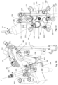
- an internal combustion engine for use with hydrogen fuel is generally indicated at 10.
- the internal combustion engine 10 has an engine block 12 and a cylinder head 14.
- the engine block 12 and the cylinder head 14 define a series of cylinders 16.
- Each cylinder 16 defines a cylinder longitudinal axis A, as shown in Figure 1 .
- Each cylinder 16 forms part of a cylinder assembly 23.
- Each cylinder assembly 23 has a piston assembly 20.
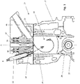
- Figure 1 shows a cross sectional view through a single cylinder assembly 23. The remaining cylinder assemblies (not shown) of the internal combustion engine 10 are substantially identical to the cylinder assembly 23 shown.
- the internal combustion engine 10 is a straight four cylinder engine, with four cylinders 16 arranged parallel to one another in a linear formation, and four piston assemblies 20 along a common crankshaft 18.
- the internal combustion engine has some other known cylinder arrangement, e.g. a straight six or V6.
- a piston head 28 of the piston assembly 20 is arranged to move in a reciprocating manner along axis A and generate rotating drive to the crankshaft 18 as is well known per se in internal combustion engines.
- the cylinder head 14 is formed within a cylinder head block 15.
- Each cylinder head 14 comprises two inlet ports 32 for air to be introduced into a combustion chamber 24 defined by the cylinder 16 and the piston assembly 20 and two outlet ports 34 for exhaust gases to be expelled.
- a spark plug 36 to ignite the hydrogen-air mixture.
- a single cylinder head block 15 is provided for all four cylinders heads 14 of the internal combustion engine 10, but in other embodiments a separate block may be provided for each cylinder head.
- the internal combustion engine 10 is of the direct injection type in this embodiment.
- the cylinder assembly 23 includes a fuel injector 22 mounted to a fuel injection port 54 for injecting fuel directly into the combustion chamber 24.
- the fuel injector 22 has a longitudinal axis B. The fuel injector is supported within the cylinder head 14.
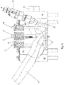
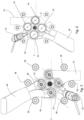
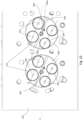
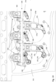
- Each cylinder head 14 is secured by six bolts 38 to the engine block 12, as best seen in Figures 2 and 5 .
- the bolts 38 are arranged symmetrically about a plane defined by a rotating axis C of the crankshaft 18 and the axis A of the cylinder 16.
- the angle between an adjacent two of the six bolts 38 is 46°.
- two sets of three bolts 38 are provided either side of the crank axis with an angle of 88° between the outermost bolts 38 of each set.
- Other angles in the range of 36° to 60° are also envisaged between bolts 38 on each side of the crank axis, which are set by the restraints of the cylinder head 14.
- Compression ignition engines are commonly used in heavy duty applications where their high torque output at low rpm is beneficial for the hauling of heavy loads, providing power to hydraulic pumps driving actuators of working arms of excavators or materials handling vehicles, or driving power take-offs to working implements such as agricultural machinery.
- hydrogen When utilising hydrogen as a fuel in such applications, it is also desirable to maintain similar torque characteristics despite the change in fuel and the need to ignite the fuel using a spark.
- Each inlet port 32 is selectably closable by a corresponding inlet valve 42, whilst each outlet port 34 is closable via a corresponding outlet valve 44.
- These inlet valves 42 and outlet valves 44 are part of a valve train 40.
- the inlet and outlet valves 42, 44 are located, when closed, in the corresponding port 32, 34 in a recessed position from an inner surface 64 of the cylinder head 14.
- the inlet ports 32 have a larger diameter than that of the outlet ports 34 in order to optimise the airflow into the combustion chamber and achieve an optimised air-hydrogen mixture for lean combustion.
- the inlet and outlet valves 42, 44 are arranged to be actuated parallel to axis A, i.e. vertically as depicted (although in certain machine installations the axis may not be vertical).
- rocker arms (not shown) for the inlet and outlet valves 42, 44 to pivot about common axes, or at least parallel axes, potentially on a single rocker shaft (not shown) extending the length of the cylinders 16.
- the engine 10 further comprises inlet runners 46 arranged to feed into the inlet ports 32 of each cylinder head 14 from an inlet manifold (not shown). As best seen in Figures 3 and 5 , the inlet runners 46 bifurcate into a first section 48 and a second section 50, the two sections 48, 50 being connected to different inlet ports 32. The first and second sections 48, 50 have non-equal lengths. The inlet runners 46 extend between two of the six bolts 38. In this way, the inlet runner 46 leaves more space available to locate components such at the spark plug 36 and fuel injector 22.
- outlet runners 47 connect the outlet ports 34 of each cylinder 16 with an exhaust manifold (not shown) and are bifurcated where they connect to each port and merge before connecting to the manifold, and extend between two of the six bolts 38 on the opposite side of the cylinder head 14.
- the inlet ports 32 and outlet ports 34 have centres that are arranged in a symmetrical fashion with respect to one another.
- the centre of each inlet port 32 is arranged in a symmetrical fashion with respect to the centre of a corresponding outlet port 34.
- the line of symmetry is a diameter bisecting the cylinder head 14.
- the inlet runner 46 is inclined with respect to a lower face of the cylinder head 14 at a relatively steep angle, which in this embodiment is approximately 36°, but may be in the range of 32° to 36°. This angle generates the tumble motion, with the upper end of the range being constrained by the packaging of other components such as the fuel injector 22, and minimising the height of the cylinder head.
- spark plug 36 is also vertically located in the centre of the cylinder head 14 intermediate the inlet and outlet ports 32, 34 to promote even combustion in the combustion chamber 24.
- spark plug 36 is an M14 diameter spark plug which has been found to be more durable that smaller diameter spark plugs when used to ignite hydrogen-air mixtures.
- the fuel injector 22 is arranged so that the injection port 54 is located intermediate one of the inlet ports 32 and one of the outlet ports 34. In this embodiment, the fuel injector 22 is arranged radially outward of a centre of one of the inlet ports 32. To permit it to be mounted within the cylinder head block 15, avoiding the bolts 38 and other features such as galleries for circulation of coolant (not shown), the injector 22 is arranged at a non-zero angle to the axis A. In this embodiment the angle is a compound angle, being 3° from the vertical of a plane defined by axes A and I or O (with a potential range of 3° to 8°) and 16° in a plane normal to A-I and A-O planes (with a potential range 11° to 21°).
- This angle may also allow the hydrogen to be injected in a direction where it better mixes with the tumbling and swirling air to further improve the homogeneity of the mixture.
- the fuel injector 22 may instead be located above the inlet runner 46 so as to inject via a port (not shown) located between the inlet ports 32 and the spark plug 36.
- the fuel injector 22 may be located below the inlet runner 46 to inject via a port (not shown) that is intermediate the two inlet ports 32 and radially outward of their centres.
- the engine 10 of the first embodiment therefore enables a compression ignition internal combustion of a configuration typically used for generating high torque at low engine speeds to achieve similar characteristics with spark ignition of hydrogen based fuels, whilst ensuring low emissions.
- an existing diesel compression ignition engine block may be utilised without adaptation. Only adaptations are required to the cylinder head 14 and in terms of core engine castings. As a result, the investment required to retool is minimised and existing supply chains may be utilised manufacture revised components. As a result a zero or low carbon prime mover may be provided at lower cost and with a shorter development time than alternatives such as hydrogen fuel cells.
- FIG. 7 to 12 A second embodiment is shown in Figures 7 to 12 .
- similar parts are denoted by the same reference numerals to the first embodiment, but with the prefix "1". Only parts which differ from the first embodiment are discussed in detail.
- each cylinder head 114 comprises a first face 158 and a second face 160 which define the flame face of the combustion chamber (that portion of the cylinder head 114 that forms a wall of the combustion chamber).
- the first face 158 and the second face 160 are generally planar and inclined relative to one another and meet at an apex 162. This is commonly referred to as a "pent roof”.
- the first face 158 is angled with respect to a plane transverse axis A by 13.5°, however, other angles in the range of 12.5° to 14.5° are also envisaged.
- the second face 160 is angled with respect to plane transverse axis A by 11.5°, however, angles in the range of 10.5° to 12.5° are also envisaged.
- These ranges of angles optimise the tumble motion of the inlet and exhaust mixtures (see curved arrow of Figure 8 ), whilst being suitable for the required packaging of components around the cylinder head 114. Any total angle greater than the range of 23° to 27° would result in problems with excessive recesses on the inner surface 164 of the cylinder head 114, impacting air-fuel mixture motion.
- the angle of the faces with respect to the plane transverse axis A differ, such that the apex 162 is offset from a centre of the flame face and the first face 158 has a smaller projected area than the second face 160.
- the apex 162 has a curved transition from the first face 158 to the second face 160.
- the two inlet ports 132 are located within the first face 158 and the two outlet ports 134 are located within the second face 160. These are fed by inlet and outlet runners 146, 147 respectively, the inlet runner 146 bifurcating into a first section 148 and a second section 150.
- the inlet ports 132 are larger than the outlet ports 134, such that in this embodiment the inlet ports 132 extend into the apex 162.
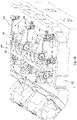
- imaginary lines I and O are arranged at a non-zero, non-right angle to the axis of rotation C of the crankshaft 118, as best seen in Figures 10 and 12 .
- the apex 162 is also arranged at a non-zero, non-right angle to the axis of rotation C of the crankshaft 118, at the same angle as that of the imaginary lines I and O.
- this skew angle is lower, being approximately 23°, which is substantially the same angle formed by a line projecting from the centres of adjacent pairs of bolts 138 intersecting with axis C.
- angles in the range of 22° to 24° are also envisioned, however this angle range is limited by needing to provide a cooling jacket around the nozzle of the fuel injector 22 located between the inlet ports 132. This allows the inlet runner 146 to extend between the bolts 138 normal to this line, and for the bifurcation being such that the first section 148 and second section 150 are of identical length and are shaped as identical mirror images.
- an axis of movement of the inlet valves 142 and outlet valves 144 are arranged substantially perpendicularly to the first face 158 and second face 160 respectively. So as to further enhance the tumble motion at least the inlet valves 142 are recessed into their respective ports 132.
- the axis of operation of the inlet valves 142 are arranged perpendicularly to the first face 158, however angles in the range of 12° to 13.5° with respect to a plane transverse axis A are also envisioned.
- the axis of operation of the outlet valves 144 are arranged perpendicularly to the second face 160.
- angles in the range of 10° to 11.5° with respect to a plane transverse axis A are also envisaged. These angles ensure that the inlet and outlet mixture flows do not soil the inner surface 164 of the cylinder head 114.
- each cylinder head 114 further comprises a channel 166 located on the inner surface 164 of the cylinder head 114.
- the channel 166 extends along the inner surface 164 in a radial orientation and is aligned with axis B of the fuel injector 122. This channel 166 prevents soiling of the inner surface 164 of the cylinder head 114 that would occur due to the angle of the fuel injector 122 and allows the hydrogen based fuel to mix effectively with the air during the inlet and compression stroke. This promotes a cleaner and more efficient combustion cycle.
- the fuel injector 122 is arranged so that the injection port 154 is located intermediate the two inlet ports 132 such that axis B of the fuel injector 122 is at an angle of 21° with respect to the plane of axis C.
- axis B of the fuel injector 122 is at an angle of 21° with respect to the plane of axis C.
- variants of this embodiment with other angles in the range of 19° to 23° are also envisioned, in order to take into account thickness constraints of the cylinder head 114 and water jacket, and to package the fuel injector 122 around the proximate components, in particular the inlet runner 146.
- the body 56 of the fuel injector 122 is located between the cylinder head 114 and a lower wall of the inlet runner 146.
- the spark plug 136 is centrally located co-axial with axis A, and is offset from the apex 162.
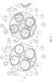
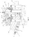
- FIG. 13 to 16 A third embodiment is shown in Figures 13 to 16 .
- similar parts are denoted by the same reference numerals to the second embodiment, but with the prefix "2" rather than "1". Only parts which differ from the first embodiment are discussed in detail.
- an internal combustion engine for use with hydrogen fuel is generally indicated at 210.
- a "pent roof” is provided by angled first and second faces 258, 260 meeting at apex 162.
- the apex 262 and imaginary lines I and O are arranged at non-zero, non-right angles to the axis of rotation C of the crankshaft 218, as best seen in Figure 14 .
- the inlet and outlet ports 232, 234 are fed by inlet and outlet runners 246, 247 respectively.
- the inlet ports 232 and outlet ports 234 have centres that are arranged in an asymmetrical fashion with respect to one another.
- the imaginary lines I and O are non-parallel in their arrangement.
- imaginary line I is parallel to the apex 262
- the imaginary line O is at a similar but non-equal angle. This difference in angle is 5.8°, however variants of this embodiment with angles in the range of 5.3° to 6.3° are also envisioned.
- This angle range is defined by valve seat inserts of the inlet ports 232 needing to be a minimum of 9mm away from each other at their closest points and the need to achieve a minimum wall thickness of 5mm around a bore of the nozzle of the fuel injector 222. This asymmetry provides additional space for mounting the injector 222 as discussed below.
- FIGS 13, 14 and 17 show two fuel injectors 222, however this is for illustrative purposes only as possible mounting locations. In use, only one fuel injector 222 is present in a selected one of these two locations.
- the fuel injector 222 is located in a port 254a that is adjacent the spark plug 236 in the space intermediate the inlet and outlet ports 232, 234. It will be appreciated that the pent roof arrangement further enables positioning at this location since the stems and return springs of the inlet and outlet valves 242, 244 are inclined away from each other. This allows for a suitable separation of the injector 222, spark plug 236 and valves, with suitably strong mountings for each, and space for coolant galleries therebetween as required.
- the injector 222 is inclined at an angle of 3° with respect to axis A in a radially outward direction to separate the injector 222 from the spark plug 236, and further to inject the hydrogen towards the centre of incoming air during the intake stroke for improved mixing.
- this embodiment with other angles in the range of 3° to 8° are also envisaged to provide for suitable targeting of the fuel, whilst not impinging on space required for the outlet ports 232 and spark plug 236.
- the injector is angled at 16 degrees to vertical axis A (i.e the angle is a compound angle) with a possible range of 11° to 21°. This range of angles allows for targeting the injected fuel flow into the mid-section of the tumble motion in the cylinder 16 with acceptable inclination and packaging of the spark plug 236.
- the fuel injector 222 may be located as in the second embodiment at an angle of 21° with respect to the plane of axis C (with other angles in the range of 19° to 23° possible).
- FIGs 13, 14 and 17 show aspects of the valve train 240 associated with this embodiment.
- the valve train comprises a cam shaft (not shown) arranged in the engine block 212 and a series of push rods 270 and rockers 272. These are arranged to open and close the inlet and outlet valves 242, 244.
- the rockers 272 comprise inlet rockers 278 and outlet rockers 280, each connected to an inlet valve 242 or outlet valve 244 respectively.
- the inlet rockers 278 rotate about an inlet rocker axis 282, whilst the outlet rockers 280 rotate about an outlet rocker axis 284.
- the arrangement allows for the valve train 240 to clear, in particular, the inlet runner whilst having the rocker shaft axes parallel with axis C.
- FIGS 18 and 19 illustrate a variant valve train 340 that may be used to actuate the inlet and outlet valves 142, 242, 144, 244 of the second and third embodiments.
- similar parts are denoted by the same reference numerals to the third embodiment, but with the prefix "3" rather than "2". Only parts which differ from the first embodiment are discussed in detail.
- the valve train 340 comprises a cam shaft (not shown) arranged in the engine block 12 and a series of push rods 370 and rockers 372. These are arranged to open and close the inlet and outlet valves 142, 242, 144, 244.
- the rockers 372 comprise inlet rockers 378 and outlet rockers 380, each connected to an inlet valve 142, 242 or outlet valve 144, 244 respectively.
- the inlet rockers 378 rotate about an inlet rocker axis 382, whilst the outlet rocker 380 rotate about an outlet rocker axis 384.
- the inlet rocker axis 382 and the outlet rocker axis 384 are distinct axes.
- the inlet rocker arm axis 382 and the outlet rocker axis 384 are parallel to each other and parallel to the cam shaft.
- the rockers 378 are formed as two arms 376a and 376b that are spaced to allow the rockers to pivot on a shaft mounted to the cylinder head 214 via a central pedestal 386, but which meet at their ends where the rockers interface with the respective pushrods 370 and bridges to actuate the valves 342, 344. This arrangement simplifies the mounting of the arms.
Landscapes
- Engineering & Computer Science (AREA)
- Chemical & Material Sciences (AREA)
- Combustion & Propulsion (AREA)
- Mechanical Engineering (AREA)
- General Engineering & Computer Science (AREA)
- Chemical Kinetics & Catalysis (AREA)
- General Chemical & Material Sciences (AREA)
- Oil, Petroleum & Natural Gas (AREA)
- Cylinder Crankcases Of Internal Combustion Engines (AREA)
Applications Claiming Priority (1)
| Application Number | Priority Date | Filing Date | Title |
|---|---|---|---|
| GB2113871.4A GB2611102A (en) | 2021-09-28 | 2021-09-28 | Internal combustion engine |
Publications (4)
| Publication Number | Publication Date |
|---|---|
| EP4155527A2 true EP4155527A2 (de) | 2023-03-29 |
| EP4155527A3 EP4155527A3 (de) | 2023-04-12 |
| EP4155527B1 EP4155527B1 (de) | 2026-01-28 |
| EP4155527C0 EP4155527C0 (de) | 2026-01-28 |
Family
ID=78399521
Family Applications (1)
| Application Number | Title | Priority Date | Filing Date |
|---|---|---|---|
| EP22197298.7A Active EP4155527B1 (de) | 2021-09-28 | 2022-09-23 | Brennkraftmaschine |
Country Status (6)
| Country | Link |
|---|---|
| US (1) | US12480436B2 (de) |
| EP (1) | EP4155527B1 (de) |
| AU (1) | AU2022241465A1 (de) |
| BR (1) | BR102022019600A2 (de) |
| CA (1) | CA3175726A1 (de) |
| GB (1) | GB2611102A (de) |
Cited By (1)
| Publication number | Priority date | Publication date | Assignee | Title |
|---|---|---|---|---|
| WO2024260945A1 (de) * | 2023-06-20 | 2024-12-26 | Alstom Holdings | Fahrzeug und entsprechendes verfahren |
Families Citing this family (2)
| Publication number | Priority date | Publication date | Assignee | Title |
|---|---|---|---|---|
| US12404802B2 (en) * | 2023-04-13 | 2025-09-02 | Saudi Arabian Oil Company | Combustion chamber for high performance H2 direct injection engine |
| CN116658294B (zh) * | 2023-06-21 | 2025-08-26 | 重庆长安汽车股份有限公司 | 一种适用于氢燃料发动机的超稀薄燃烧系统、分区燃烧控制方法及车辆 |
Family Cites Families (20)
| Publication number | Priority date | Publication date | Assignee | Title |
|---|---|---|---|---|
| DE1258654B (de) * | 1965-12-10 | 1968-01-11 | Maybach Mercedes Benz Motorenb | Fluessigkeitsgekuehlter Zylinderkopf fuer Brennkraftmaschinen |
| AT326422B (de) * | 1971-08-03 | 1975-12-10 | List Hans | Zylinderkopf für eine brennkraftmaschine |
| SE401239B (sv) * | 1972-05-10 | 1978-04-24 | List Hans | Forbrenningsmotor av insprutningstyp |
| JPS62159729A (ja) * | 1986-01-08 | 1987-07-15 | Fuji Heavy Ind Ltd | 内燃機関の吸気ポ−ト |
| US4958604A (en) * | 1988-02-10 | 1990-09-25 | Toyota Jidosha Kabushiki Kaisha | Direct fuel injection type spark ignition internal combustion engine |
| AT402433B (de) * | 1989-04-11 | 1997-05-26 | Avl Verbrennungskraft Messtech | Zylinderkopf für eine brennkraftmaschine |
| SE470267B (sv) * | 1992-12-23 | 1993-12-20 | Saab Scania Ab | Cylinderhuvud för förbränningsmotor |
| US5429086A (en) * | 1994-02-14 | 1995-07-04 | Cummins Engine Company, Inc. | Shared runner intake ports for I.C. engine |
| JPH108971A (ja) * | 1996-06-19 | 1998-01-13 | Yamaha Motor Co Ltd | 筒内燃料噴射式エンジン |
| US5873331A (en) * | 1997-03-29 | 1999-02-23 | Daimler-Benz A.G. | Cylinder head for a multi-cylinder internal combustion engine |
| DE10035239B4 (de) * | 2000-07-20 | 2011-04-21 | Daimler Ag | Brennkraftmaschine |
| JP2004076679A (ja) * | 2002-08-21 | 2004-03-11 | Toyota Motor Corp | 内燃機関の気体燃料添加方法及び気体燃料添加装置 |
| JP4680828B2 (ja) * | 2006-05-11 | 2011-05-11 | 本田技研工業株式会社 | エンジンの吸気ポ−ト構造 |
| US7980220B2 (en) * | 2007-10-04 | 2011-07-19 | Ford Global Technologies, Llc | Staggered intake valve opening with bifurcated port to eliminate hydrogen intake backfire |
| WO2009130777A1 (ja) * | 2008-04-24 | 2009-10-29 | トヨタ自動車株式会社 | 多種燃料内燃機関 |
| US8899207B2 (en) * | 2009-10-14 | 2014-12-02 | Southwest Research Institute | Cylinder head for an engine |
| KR102058755B1 (ko) * | 2012-12-26 | 2020-01-22 | 두산인프라코어 주식회사 | 엔진의 흡기구 구조 |
| JP6051133B2 (ja) * | 2013-09-25 | 2016-12-27 | 株式会社クボタ | エンジンの吸気装置 |
| CN204060916U (zh) * | 2014-02-26 | 2014-12-31 | 西港能源有限公司 | 用于气体燃料内燃发动机的进气道和阀座的配置 |
| GB2553821B (en) * | 2016-09-15 | 2020-04-01 | Perkins Engines Co Ltd | Cylinder head with helical inlet passage |
-
2021
- 2021-09-28 GB GB2113871.4A patent/GB2611102A/en active Pending
-
2022
- 2022-09-21 CA CA3175726A patent/CA3175726A1/en active Pending
- 2022-09-23 EP EP22197298.7A patent/EP4155527B1/de active Active
- 2022-09-26 AU AU2022241465A patent/AU2022241465A1/en active Pending
- 2022-09-28 US US17/955,527 patent/US12480436B2/en active Active
- 2022-09-28 BR BR102022019600-1A patent/BR102022019600A2/pt unknown
Cited By (1)
| Publication number | Priority date | Publication date | Assignee | Title |
|---|---|---|---|---|
| WO2024260945A1 (de) * | 2023-06-20 | 2024-12-26 | Alstom Holdings | Fahrzeug und entsprechendes verfahren |
Also Published As
| Publication number | Publication date |
|---|---|
| AU2022241465A1 (en) | 2023-04-13 |
| EP4155527B1 (de) | 2026-01-28 |
| BR102022019600A2 (pt) | 2023-04-11 |
| US12480436B2 (en) | 2025-11-25 |
| US20230100541A1 (en) | 2023-03-30 |
| CA3175726A1 (en) | 2023-03-28 |
| GB2611102A (en) | 2023-03-29 |
| EP4155527C0 (de) | 2026-01-28 |
| GB202113871D0 (en) | 2021-11-10 |
| EP4155527A3 (de) | 2023-04-12 |
Similar Documents
| Publication | Publication Date | Title |
|---|---|---|
| EP4155527B1 (de) | Brennkraftmaschine | |
| CN113482763B (zh) | 用于供给有气体燃料的内燃发动机的燃烧装置 | |
| US9695723B2 (en) | Combustion system including a piston crown and fuel injector | |
| JP5741594B2 (ja) | 燃焼エンジンシリンダ内で往復移動するように配置されたピストン | |
| US20090194065A1 (en) | Rotary Piston Type Internal Combustion Engine | |
| US12486795B2 (en) | Internal combustion engine | |
| US11143094B2 (en) | Gas inlet device with intersection of the inlet duct and the valve calibration inclined with respect to the fire face | |
| CN117967444A (zh) | 内燃发动机 | |
| CN117967443A (zh) | 内燃发动机 | |
| US10738729B2 (en) | Direct-injection internal combustion engine with two valves per cylinder | |
| GB2636876A (en) | Internal combustion engine | |
| GB2623804A (en) | An engine | |
| EP4579068A1 (de) | Zylinderkopf und verbrennungsmotorsystem | |
| GB2642798A (en) | Coolant jacket | |
| CN116490679A (zh) | 适用于气体空气动力学运动的内燃机活塞 | |
| Ghetti | Optimization of powertrain layout to maximize benefits of an H2 internal combustion engine | |
| JPH09324633A (ja) | 筒内直噴式内燃機関 | |
| JPH03182618A (ja) | 多弁式エンジンの燃焼室構造 |
Legal Events
| Date | Code | Title | Description |
|---|---|---|---|
| PUAI | Public reference made under article 153(3) epc to a published international application that has entered the european phase |
Free format text: ORIGINAL CODE: 0009012 |
|
| STAA | Information on the status of an ep patent application or granted ep patent |
Free format text: STATUS: REQUEST FOR EXAMINATION WAS MADE |
|
| PUAL | Search report despatched |
Free format text: ORIGINAL CODE: 0009013 |
|
| 17P | Request for examination filed |
Effective date: 20220926 |
|
| AK | Designated contracting states |
Kind code of ref document: A2 Designated state(s): AL AT BE BG CH CY CZ DE DK EE ES FI FR GB GR HR HU IE IS IT LI LT LU LV MC MK MT NL NO PL PT RO RS SE SI SK SM TR |
|
| AK | Designated contracting states |
Kind code of ref document: A3 Designated state(s): AL AT BE BG CH CY CZ DE DK EE ES FI FR GB GR HR HU IE IS IT LI LT LU LV MC MK MT NL NO PL PT RO RS SE SI SK SM TR |
|
| RIC1 | Information provided on ipc code assigned before grant |
Ipc: F02F 1/24 20060101ALI20230308BHEP Ipc: F02M 39/00 20060101AFI20230308BHEP |
|
| STAA | Information on the status of an ep patent application or granted ep patent |
Free format text: STATUS: EXAMINATION IS IN PROGRESS |
|
| 17Q | First examination report despatched |
Effective date: 20240702 |
|
| P01 | Opt-out of the competence of the unified patent court (upc) registered |
Free format text: CASE NUMBER: APP_46/2025 Effective date: 20250102 |
|
| REG | Reference to a national code |
Ref country code: DE Ref legal event code: R079 Ref document number: 602022029172 Country of ref document: DE Free format text: PREVIOUS MAIN CLASS: F02M0039000000 Ipc: F02M0061140000 |
|
| RIC1 | Information provided on ipc code assigned before grant |
Ipc: F02M 61/14 20060101AFI20250625BHEP Ipc: F02F 1/24 20060101ALI20250625BHEP |
|
| GRAP | Despatch of communication of intention to grant a patent |
Free format text: ORIGINAL CODE: EPIDOSNIGR1 |
|
| STAA | Information on the status of an ep patent application or granted ep patent |
Free format text: STATUS: GRANT OF PATENT IS INTENDED |
|
| INTG | Intention to grant announced |
Effective date: 20250826 |
|
| GRAS | Grant fee paid |
Free format text: ORIGINAL CODE: EPIDOSNIGR3 |
|
| GRAA | (expected) grant |
Free format text: ORIGINAL CODE: 0009210 |
|
| STAA | Information on the status of an ep patent application or granted ep patent |
Free format text: STATUS: THE PATENT HAS BEEN GRANTED |
|
| AK | Designated contracting states |
Kind code of ref document: B1 Designated state(s): AL AT BE BG CH CY CZ DE DK EE ES FI FR GB GR HR HU IE IS IT LI LT LU LV MC MK MT NL NO PL PT RO RS SE SI SK SM TR |
|
| REG | Reference to a national code |
Ref country code: CH Ref legal event code: F10 Free format text: ST27 STATUS EVENT CODE: U-0-0-F10-F00 (AS PROVIDED BY THE NATIONAL OFFICE) Effective date: 20260128 Ref country code: GB Ref legal event code: FG4D |
|
| REG | Reference to a national code |
Ref country code: DE Ref legal event code: R096 Ref document number: 602022029172 Country of ref document: DE |
|
| REG | Reference to a national code |
Ref country code: IE Ref legal event code: FG4D |
|
| U01 | Request for unitary effect filed |
Effective date: 20260225 |
|
| P04 | Withdrawal of opt-out of the competence of the unified patent court (upc) registered |
Free format text: CASE NUMBER: APP_46_1/2025 Effective date: 20260304 |
|
| U07 | Unitary effect registered |
Designated state(s): AT BE BG DE DK EE FI FR IT LT LU LV MT NL PT RO SE SI Effective date: 20260304 |