EP4155259A1 - Method for producing synthesis gas with reduced steam export - Google Patents
Method for producing synthesis gas with reduced steam export Download PDFInfo
- Publication number
- EP4155259A1 EP4155259A1 EP21020475.6A EP21020475A EP4155259A1 EP 4155259 A1 EP4155259 A1 EP 4155259A1 EP 21020475 A EP21020475 A EP 21020475A EP 4155259 A1 EP4155259 A1 EP 4155259A1
- Authority
- EP
- European Patent Office
- Prior art keywords
- steam
- reformer
- tube
- mol
- tubes
- Prior art date
- Legal status (The legal status is an assumption and is not a legal conclusion. Google has not performed a legal analysis and makes no representation as to the accuracy of the status listed.)
- Pending
Links
- 230000015572 biosynthetic process Effects 0.000 title claims abstract description 34
- 238000003786 synthesis reaction Methods 0.000 title claims abstract description 34
- 230000002829 reductive effect Effects 0.000 title claims abstract description 22
- 238000004519 manufacturing process Methods 0.000 title description 13
- 239000003054 catalyst Substances 0.000 claims abstract description 122
- 239000007789 gas Substances 0.000 claims abstract description 99
- 238000000629 steam reforming Methods 0.000 claims abstract description 56
- 238000000034 method Methods 0.000 claims abstract description 53
- 229910052739 hydrogen Inorganic materials 0.000 claims abstract description 33
- 239000001257 hydrogen Substances 0.000 claims abstract description 33
- UFHFLCQGNIYNRP-UHFFFAOYSA-N Hydrogen Chemical compound [H][H] UFHFLCQGNIYNRP-UHFFFAOYSA-N 0.000 claims abstract description 29
- UGFAIRIUMAVXCW-UHFFFAOYSA-N Carbon monoxide Chemical compound [O+]#[C-] UGFAIRIUMAVXCW-UHFFFAOYSA-N 0.000 claims abstract description 18
- 239000003546 flue gas Substances 0.000 claims abstract description 6
- VNWKTOKETHGBQD-UHFFFAOYSA-N methane Chemical compound C VNWKTOKETHGBQD-UHFFFAOYSA-N 0.000 claims description 60
- 238000002407 reforming Methods 0.000 claims description 37
- 230000008569 process Effects 0.000 claims description 31
- 238000006243 chemical reaction Methods 0.000 claims description 28
- 238000012856 packing Methods 0.000 claims description 20
- 239000003345 natural gas Substances 0.000 claims description 19
- 229930195733 hydrocarbon Natural products 0.000 claims description 17
- 150000002430 hydrocarbons Chemical class 0.000 claims description 17
- 229910052799 carbon Inorganic materials 0.000 claims description 13
- 239000004215 Carbon black (E152) Substances 0.000 claims description 8
- CURLTUGMZLYLDI-UHFFFAOYSA-N Carbon dioxide Chemical compound O=C=O CURLTUGMZLYLDI-UHFFFAOYSA-N 0.000 claims description 8
- 241000282326 Felis catus Species 0.000 claims description 7
- 229910002090 carbon oxide Inorganic materials 0.000 claims description 6
- 230000003197 catalytic effect Effects 0.000 claims description 6
- 239000000463 material Substances 0.000 claims description 6
- 239000000919 ceramic Substances 0.000 claims description 5
- 239000012530 fluid Substances 0.000 claims description 5
- 241000264877 Hippospongia communis Species 0.000 claims description 4
- 229910002092 carbon dioxide Inorganic materials 0.000 claims description 4
- 239000001569 carbon dioxide Substances 0.000 claims description 4
- 238000001193 catalytic steam reforming Methods 0.000 claims description 2
- 239000006260 foam Substances 0.000 claims description 2
- 238000007599 discharging Methods 0.000 claims 2
- 101100173048 Mus musculus Mcat gene Proteins 0.000 claims 1
- 238000001816 cooling Methods 0.000 claims 1
- 239000000498 cooling water Substances 0.000 claims 1
- 230000002195 synergetic effect Effects 0.000 abstract description 2
- 239000000047 product Substances 0.000 description 21
- 238000012546 transfer Methods 0.000 description 18
- 239000008188 pellet Substances 0.000 description 15
- 230000008901 benefit Effects 0.000 description 10
- 238000013461 design Methods 0.000 description 10
- 238000005260 corrosion Methods 0.000 description 9
- OKTJSMMVPCPJKN-UHFFFAOYSA-N Carbon Chemical compound [C] OKTJSMMVPCPJKN-UHFFFAOYSA-N 0.000 description 8
- 229910002091 carbon monoxide Inorganic materials 0.000 description 7
- 230000007797 corrosion Effects 0.000 description 7
- PXHVJJICTQNCMI-UHFFFAOYSA-N Nickel Chemical compound [Ni] PXHVJJICTQNCMI-UHFFFAOYSA-N 0.000 description 6
- 229910052751 metal Inorganic materials 0.000 description 6
- 239000002184 metal Substances 0.000 description 6
- 230000000694 effects Effects 0.000 description 5
- 238000010410 dusting Methods 0.000 description 4
- 238000010438 heat treatment Methods 0.000 description 4
- 150000002431 hydrogen Chemical class 0.000 description 4
- 238000011084 recovery Methods 0.000 description 4
- 230000009467 reduction Effects 0.000 description 4
- OKKJLVBELUTLKV-UHFFFAOYSA-N Methanol Chemical compound OC OKKJLVBELUTLKV-UHFFFAOYSA-N 0.000 description 3
- 244000089486 Phragmites australis subsp australis Species 0.000 description 3
- 229910052782 aluminium Inorganic materials 0.000 description 3
- XAGFODPZIPBFFR-UHFFFAOYSA-N aluminium Chemical compound [Al] XAGFODPZIPBFFR-UHFFFAOYSA-N 0.000 description 3
- 239000011248 coating agent Substances 0.000 description 3
- 238000000576 coating method Methods 0.000 description 3
- 239000012043 crude product Substances 0.000 description 3
- 230000004907 flux Effects 0.000 description 3
- 239000011810 insulating material Substances 0.000 description 3
- 238000011835 investigation Methods 0.000 description 3
- 239000000203 mixture Substances 0.000 description 3
- 229910052759 nickel Inorganic materials 0.000 description 3
- 230000036961 partial effect Effects 0.000 description 3
- 239000002245 particle Substances 0.000 description 3
- 239000002918 waste heat Substances 0.000 description 3
- QGZKDVFQNNGYKY-UHFFFAOYSA-N Ammonia Chemical compound N QGZKDVFQNNGYKY-UHFFFAOYSA-N 0.000 description 2
- 229910045601 alloy Inorganic materials 0.000 description 2
- 239000000956 alloy Substances 0.000 description 2
- 238000013459 approach Methods 0.000 description 2
- 238000011161 development Methods 0.000 description 2
- 230000018109 developmental process Effects 0.000 description 2
- 238000009792 diffusion process Methods 0.000 description 2
- 238000009826 distribution Methods 0.000 description 2
- 230000002349 favourable effect Effects 0.000 description 2
- 239000007769 metal material Substances 0.000 description 2
- 238000012986 modification Methods 0.000 description 2
- 230000004048 modification Effects 0.000 description 2
- 238000005457 optimization Methods 0.000 description 2
- 230000005855 radiation Effects 0.000 description 2
- RYGMFSIKBFXOCR-UHFFFAOYSA-N Copper Chemical compound [Cu] RYGMFSIKBFXOCR-UHFFFAOYSA-N 0.000 description 1
- 229910000990 Ni alloy Inorganic materials 0.000 description 1
- 229910018487 Ni—Cr Inorganic materials 0.000 description 1
- NPXOKRUENSOPAO-UHFFFAOYSA-N Raney nickel Chemical compound [Al].[Ni] NPXOKRUENSOPAO-UHFFFAOYSA-N 0.000 description 1
- 229910000831 Steel Inorganic materials 0.000 description 1
- 239000006096 absorbing agent Substances 0.000 description 1
- 239000011149 active material Substances 0.000 description 1
- 230000002411 adverse Effects 0.000 description 1
- 229910021529 ammonia Inorganic materials 0.000 description 1
- 238000006555 catalytic reaction Methods 0.000 description 1
- 229910010293 ceramic material Inorganic materials 0.000 description 1
- VNNRSPGTAMTISX-UHFFFAOYSA-N chromium nickel Chemical compound [Cr].[Ni] VNNRSPGTAMTISX-UHFFFAOYSA-N 0.000 description 1
- 238000002485 combustion reaction Methods 0.000 description 1
- 230000006835 compression Effects 0.000 description 1
- 238000007906 compression Methods 0.000 description 1
- 230000003750 conditioning effect Effects 0.000 description 1
- 238000010276 construction Methods 0.000 description 1
- 229910052802 copper Inorganic materials 0.000 description 1
- 239000010949 copper Substances 0.000 description 1
- 230000003247 decreasing effect Effects 0.000 description 1
- 230000001419 dependent effect Effects 0.000 description 1
- 230000004069 differentiation Effects 0.000 description 1
- 238000004821 distillation Methods 0.000 description 1
- 238000011143 downstream manufacturing Methods 0.000 description 1
- 238000005516 engineering process Methods 0.000 description 1
- 239000000835 fiber Substances 0.000 description 1
- 238000011049 filling Methods 0.000 description 1
- 238000005243 fluidization Methods 0.000 description 1
- 239000011888 foil Substances 0.000 description 1
- 230000006870 function Effects 0.000 description 1
- 238000002309 gasification Methods 0.000 description 1
- 230000001771 impaired effect Effects 0.000 description 1
- 230000006872 improvement Effects 0.000 description 1
- 238000007689 inspection Methods 0.000 description 1
- 238000009434 installation Methods 0.000 description 1
- 230000000670 limiting effect Effects 0.000 description 1
- 230000007246 mechanism Effects 0.000 description 1
- 238000000465 moulding Methods 0.000 description 1
- -1 naphtha Chemical class 0.000 description 1
- CLDVQCMGOSGNIW-UHFFFAOYSA-N nickel tin Chemical compound [Ni].[Sn] CLDVQCMGOSGNIW-UHFFFAOYSA-N 0.000 description 1
- 238000013021 overheating Methods 0.000 description 1
- 238000004806 packaging method and process Methods 0.000 description 1
- 238000012545 processing Methods 0.000 description 1
- 239000011819 refractory material Substances 0.000 description 1
- 238000005201 scrubbing Methods 0.000 description 1
- 239000011949 solid catalyst Substances 0.000 description 1
- 210000002023 somite Anatomy 0.000 description 1
- 238000001179 sorption measurement Methods 0.000 description 1
- 239000007858 starting material Substances 0.000 description 1
- 238000001991 steam methane reforming Methods 0.000 description 1
- 239000010959 steel Substances 0.000 description 1
- 239000000126 substance Substances 0.000 description 1
- 230000007306 turnover Effects 0.000 description 1
- 239000011800 void material Substances 0.000 description 1
- XLYOFNOQVPJJNP-UHFFFAOYSA-N water Substances O XLYOFNOQVPJJNP-UHFFFAOYSA-N 0.000 description 1
- 238000010626 work up procedure Methods 0.000 description 1
Images
Classifications
-
- C—CHEMISTRY; METALLURGY
- C01—INORGANIC CHEMISTRY
- C01B—NON-METALLIC ELEMENTS; COMPOUNDS THEREOF; METALLOIDS OR COMPOUNDS THEREOF NOT COVERED BY SUBCLASS C01C
- C01B3/00—Hydrogen; Gaseous mixtures containing hydrogen; Separation of hydrogen from mixtures containing it; Purification of hydrogen
- C01B3/02—Production of hydrogen or of gaseous mixtures containing a substantial proportion of hydrogen
- C01B3/32—Production of hydrogen or of gaseous mixtures containing a substantial proportion of hydrogen by reaction of gaseous or liquid organic compounds with gasifying agents, e.g. water, carbon dioxide, air
- C01B3/34—Production of hydrogen or of gaseous mixtures containing a substantial proportion of hydrogen by reaction of gaseous or liquid organic compounds with gasifying agents, e.g. water, carbon dioxide, air by reaction of hydrocarbons with gasifying agents
- C01B3/38—Production of hydrogen or of gaseous mixtures containing a substantial proportion of hydrogen by reaction of gaseous or liquid organic compounds with gasifying agents, e.g. water, carbon dioxide, air by reaction of hydrocarbons with gasifying agents using catalysts
- C01B3/388—Production of hydrogen or of gaseous mixtures containing a substantial proportion of hydrogen by reaction of gaseous or liquid organic compounds with gasifying agents, e.g. water, carbon dioxide, air by reaction of hydrocarbons with gasifying agents using catalysts the heat being generated by superheated steam
-
- C—CHEMISTRY; METALLURGY
- C01—INORGANIC CHEMISTRY
- C01B—NON-METALLIC ELEMENTS; COMPOUNDS THEREOF; METALLOIDS OR COMPOUNDS THEREOF NOT COVERED BY SUBCLASS C01C
- C01B3/00—Hydrogen; Gaseous mixtures containing hydrogen; Separation of hydrogen from mixtures containing it; Purification of hydrogen
- C01B3/02—Production of hydrogen or of gaseous mixtures containing a substantial proportion of hydrogen
- C01B3/32—Production of hydrogen or of gaseous mixtures containing a substantial proportion of hydrogen by reaction of gaseous or liquid organic compounds with gasifying agents, e.g. water, carbon dioxide, air
- C01B3/34—Production of hydrogen or of gaseous mixtures containing a substantial proportion of hydrogen by reaction of gaseous or liquid organic compounds with gasifying agents, e.g. water, carbon dioxide, air by reaction of hydrocarbons with gasifying agents
- C01B3/38—Production of hydrogen or of gaseous mixtures containing a substantial proportion of hydrogen by reaction of gaseous or liquid organic compounds with gasifying agents, e.g. water, carbon dioxide, air by reaction of hydrocarbons with gasifying agents using catalysts
- C01B3/384—Production of hydrogen or of gaseous mixtures containing a substantial proportion of hydrogen by reaction of gaseous or liquid organic compounds with gasifying agents, e.g. water, carbon dioxide, air by reaction of hydrocarbons with gasifying agents using catalysts the catalyst being continuously externally heated
-
- B—PERFORMING OPERATIONS; TRANSPORTING
- B01—PHYSICAL OR CHEMICAL PROCESSES OR APPARATUS IN GENERAL
- B01J—CHEMICAL OR PHYSICAL PROCESSES, e.g. CATALYSIS OR COLLOID CHEMISTRY; THEIR RELEVANT APPARATUS
- B01J19/00—Chemical, physical or physico-chemical processes in general; Their relevant apparatus
- B01J19/24—Stationary reactors without moving elements inside
- B01J19/2455—Stationary reactors without moving elements inside provoking a loop type movement of the reactants
- B01J19/246—Stationary reactors without moving elements inside provoking a loop type movement of the reactants internally, i.e. the mixture circulating inside the vessel such that the upward stream is separated physically from the downward stream(s)
-
- B—PERFORMING OPERATIONS; TRANSPORTING
- B01—PHYSICAL OR CHEMICAL PROCESSES OR APPARATUS IN GENERAL
- B01J—CHEMICAL OR PHYSICAL PROCESSES, e.g. CATALYSIS OR COLLOID CHEMISTRY; THEIR RELEVANT APPARATUS
- B01J19/00—Chemical, physical or physico-chemical processes in general; Their relevant apparatus
- B01J19/24—Stationary reactors without moving elements inside
- B01J19/248—Reactors comprising multiple separated flow channels
- B01J19/2485—Monolithic reactors
-
- B—PERFORMING OPERATIONS; TRANSPORTING
- B01—PHYSICAL OR CHEMICAL PROCESSES OR APPARATUS IN GENERAL
- B01J—CHEMICAL OR PHYSICAL PROCESSES, e.g. CATALYSIS OR COLLOID CHEMISTRY; THEIR RELEVANT APPARATUS
- B01J19/00—Chemical, physical or physico-chemical processes in general; Their relevant apparatus
- B01J19/32—Packing elements in the form of grids or built-up elements for forming a unit or module inside the apparatus for mass or heat transfer
-
- B—PERFORMING OPERATIONS; TRANSPORTING
- B01—PHYSICAL OR CHEMICAL PROCESSES OR APPARATUS IN GENERAL
- B01J—CHEMICAL OR PHYSICAL PROCESSES, e.g. CATALYSIS OR COLLOID CHEMISTRY; THEIR RELEVANT APPARATUS
- B01J8/00—Chemical or physical processes in general, conducted in the presence of fluids and solid particles; Apparatus for such processes
- B01J8/02—Chemical or physical processes in general, conducted in the presence of fluids and solid particles; Apparatus for such processes with stationary particles, e.g. in fixed beds
- B01J8/06—Chemical or physical processes in general, conducted in the presence of fluids and solid particles; Apparatus for such processes with stationary particles, e.g. in fixed beds in tube reactors; the solid particles being arranged in tubes
- B01J8/062—Chemical or physical processes in general, conducted in the presence of fluids and solid particles; Apparatus for such processes with stationary particles, e.g. in fixed beds in tube reactors; the solid particles being arranged in tubes being installed in a furnace
-
- B—PERFORMING OPERATIONS; TRANSPORTING
- B01—PHYSICAL OR CHEMICAL PROCESSES OR APPARATUS IN GENERAL
- B01J—CHEMICAL OR PHYSICAL PROCESSES, e.g. CATALYSIS OR COLLOID CHEMISTRY; THEIR RELEVANT APPARATUS
- B01J2219/00—Chemical, physical or physico-chemical processes in general; Their relevant apparatus
- B01J2219/32—Details relating to packing elements in the form of grids or built-up elements for forming a unit of module inside the apparatus for mass or heat transfer
- B01J2219/324—Composition or microstructure of the elements
- B01J2219/32466—Composition or microstructure of the elements comprising catalytically active material
- B01J2219/32475—Composition or microstructure of the elements comprising catalytically active material involving heat exchange
-
- C—CHEMISTRY; METALLURGY
- C01—INORGANIC CHEMISTRY
- C01B—NON-METALLIC ELEMENTS; COMPOUNDS THEREOF; METALLOIDS OR COMPOUNDS THEREOF NOT COVERED BY SUBCLASS C01C
- C01B2203/00—Integrated processes for the production of hydrogen or synthesis gas
- C01B2203/02—Processes for making hydrogen or synthesis gas
- C01B2203/0205—Processes for making hydrogen or synthesis gas containing a reforming step
- C01B2203/0227—Processes for making hydrogen or synthesis gas containing a reforming step containing a catalytic reforming step
- C01B2203/0233—Processes for making hydrogen or synthesis gas containing a reforming step containing a catalytic reforming step the reforming step being a steam reforming step
-
- C—CHEMISTRY; METALLURGY
- C01—INORGANIC CHEMISTRY
- C01B—NON-METALLIC ELEMENTS; COMPOUNDS THEREOF; METALLOIDS OR COMPOUNDS THEREOF NOT COVERED BY SUBCLASS C01C
- C01B2203/00—Integrated processes for the production of hydrogen or synthesis gas
- C01B2203/02—Processes for making hydrogen or synthesis gas
- C01B2203/0283—Processes for making hydrogen or synthesis gas containing a CO-shift step, i.e. a water gas shift step
-
- C—CHEMISTRY; METALLURGY
- C01—INORGANIC CHEMISTRY
- C01B—NON-METALLIC ELEMENTS; COMPOUNDS THEREOF; METALLOIDS OR COMPOUNDS THEREOF NOT COVERED BY SUBCLASS C01C
- C01B2203/00—Integrated processes for the production of hydrogen or synthesis gas
- C01B2203/04—Integrated processes for the production of hydrogen or synthesis gas containing a purification step for the hydrogen or the synthesis gas
- C01B2203/0415—Purification by absorption in liquids
-
- C—CHEMISTRY; METALLURGY
- C01—INORGANIC CHEMISTRY
- C01B—NON-METALLIC ELEMENTS; COMPOUNDS THEREOF; METALLOIDS OR COMPOUNDS THEREOF NOT COVERED BY SUBCLASS C01C
- C01B2203/00—Integrated processes for the production of hydrogen or synthesis gas
- C01B2203/04—Integrated processes for the production of hydrogen or synthesis gas containing a purification step for the hydrogen or the synthesis gas
- C01B2203/042—Purification by adsorption on solids
- C01B2203/043—Regenerative adsorption process in two or more beds, one for adsorption, the other for regeneration
-
- C—CHEMISTRY; METALLURGY
- C01—INORGANIC CHEMISTRY
- C01B—NON-METALLIC ELEMENTS; COMPOUNDS THEREOF; METALLOIDS OR COMPOUNDS THEREOF NOT COVERED BY SUBCLASS C01C
- C01B2203/00—Integrated processes for the production of hydrogen or synthesis gas
- C01B2203/08—Methods of heating or cooling
- C01B2203/0805—Methods of heating the process for making hydrogen or synthesis gas
- C01B2203/0811—Methods of heating the process for making hydrogen or synthesis gas by combustion of fuel
- C01B2203/0816—Heating by flames
-
- C—CHEMISTRY; METALLURGY
- C01—INORGANIC CHEMISTRY
- C01B—NON-METALLIC ELEMENTS; COMPOUNDS THEREOF; METALLOIDS OR COMPOUNDS THEREOF NOT COVERED BY SUBCLASS C01C
- C01B2203/00—Integrated processes for the production of hydrogen or synthesis gas
- C01B2203/08—Methods of heating or cooling
- C01B2203/0805—Methods of heating the process for making hydrogen or synthesis gas
- C01B2203/0866—Methods of heating the process for making hydrogen or synthesis gas by combination of different heating methods
-
- C—CHEMISTRY; METALLURGY
- C01—INORGANIC CHEMISTRY
- C01B—NON-METALLIC ELEMENTS; COMPOUNDS THEREOF; METALLOIDS OR COMPOUNDS THEREOF NOT COVERED BY SUBCLASS C01C
- C01B2203/00—Integrated processes for the production of hydrogen or synthesis gas
- C01B2203/08—Methods of heating or cooling
- C01B2203/0872—Methods of cooling
- C01B2203/0883—Methods of cooling by indirect heat exchange
-
- C—CHEMISTRY; METALLURGY
- C01—INORGANIC CHEMISTRY
- C01B—NON-METALLIC ELEMENTS; COMPOUNDS THEREOF; METALLOIDS OR COMPOUNDS THEREOF NOT COVERED BY SUBCLASS C01C
- C01B2203/00—Integrated processes for the production of hydrogen or synthesis gas
- C01B2203/08—Methods of heating or cooling
- C01B2203/0872—Methods of cooling
- C01B2203/0888—Methods of cooling by evaporation of a fluid
- C01B2203/0894—Generation of steam
-
- C—CHEMISTRY; METALLURGY
- C01—INORGANIC CHEMISTRY
- C01B—NON-METALLIC ELEMENTS; COMPOUNDS THEREOF; METALLOIDS OR COMPOUNDS THEREOF NOT COVERED BY SUBCLASS C01C
- C01B2203/00—Integrated processes for the production of hydrogen or synthesis gas
- C01B2203/10—Catalysts for performing the hydrogen forming reactions
- C01B2203/1005—Arrangement or shape of catalyst
- C01B2203/1011—Packed bed of catalytic structures, e.g. particles, packing elements
- C01B2203/1017—Packed bed of catalytic structures, e.g. particles, packing elements characterised by the form of the structure
-
- C—CHEMISTRY; METALLURGY
- C01—INORGANIC CHEMISTRY
- C01B—NON-METALLIC ELEMENTS; COMPOUNDS THEREOF; METALLOIDS OR COMPOUNDS THEREOF NOT COVERED BY SUBCLASS C01C
- C01B2203/00—Integrated processes for the production of hydrogen or synthesis gas
- C01B2203/10—Catalysts for performing the hydrogen forming reactions
- C01B2203/1005—Arrangement or shape of catalyst
- C01B2203/1023—Catalysts in the form of a monolith or honeycomb
-
- C—CHEMISTRY; METALLURGY
- C01—INORGANIC CHEMISTRY
- C01B—NON-METALLIC ELEMENTS; COMPOUNDS THEREOF; METALLOIDS OR COMPOUNDS THEREOF NOT COVERED BY SUBCLASS C01C
- C01B2203/00—Integrated processes for the production of hydrogen or synthesis gas
- C01B2203/10—Catalysts for performing the hydrogen forming reactions
- C01B2203/1005—Arrangement or shape of catalyst
- C01B2203/1029—Catalysts in the form of a foam
-
- C—CHEMISTRY; METALLURGY
- C01—INORGANIC CHEMISTRY
- C01B—NON-METALLIC ELEMENTS; COMPOUNDS THEREOF; METALLOIDS OR COMPOUNDS THEREOF NOT COVERED BY SUBCLASS C01C
- C01B2203/00—Integrated processes for the production of hydrogen or synthesis gas
- C01B2203/10—Catalysts for performing the hydrogen forming reactions
- C01B2203/1041—Composition of the catalyst
- C01B2203/1047—Group VIII metal catalysts
- C01B2203/1052—Nickel or cobalt catalysts
- C01B2203/1058—Nickel catalysts
-
- C—CHEMISTRY; METALLURGY
- C01—INORGANIC CHEMISTRY
- C01B—NON-METALLIC ELEMENTS; COMPOUNDS THEREOF; METALLOIDS OR COMPOUNDS THEREOF NOT COVERED BY SUBCLASS C01C
- C01B2203/00—Integrated processes for the production of hydrogen or synthesis gas
- C01B2203/12—Feeding the process for making hydrogen or synthesis gas
- C01B2203/1205—Composition of the feed
- C01B2203/1211—Organic compounds or organic mixtures used in the process for making hydrogen or synthesis gas
- C01B2203/1235—Hydrocarbons
- C01B2203/1241—Natural gas or methane
-
- C—CHEMISTRY; METALLURGY
- C01—INORGANIC CHEMISTRY
- C01B—NON-METALLIC ELEMENTS; COMPOUNDS THEREOF; METALLOIDS OR COMPOUNDS THEREOF NOT COVERED BY SUBCLASS C01C
- C01B2203/00—Integrated processes for the production of hydrogen or synthesis gas
- C01B2203/16—Controlling the process
- C01B2203/1614—Controlling the temperature
-
- C—CHEMISTRY; METALLURGY
- C01—INORGANIC CHEMISTRY
- C01B—NON-METALLIC ELEMENTS; COMPOUNDS THEREOF; METALLOIDS OR COMPOUNDS THEREOF NOT COVERED BY SUBCLASS C01C
- C01B2203/00—Integrated processes for the production of hydrogen or synthesis gas
- C01B2203/16—Controlling the process
- C01B2203/169—Controlling the feed
Definitions
- the invention relates to a method for producing a synthesis gas containing hydrogen and carbon oxides with reduced steam export by catalytic steam reforming of a hydrocarbon-containing feed gas, preferably natural gas, with steam under steam reforming conditions in a plurality of reformer tubes in a burner-heated reformer furnace to form a steam reforming flue gas.
- Hydrocarbons can be catalytically converted with steam to synthesis gas, i.e. mixtures of hydrogen (H 2 ) and carbon monoxide (CO).
- synthesis gas i.e. mixtures of hydrogen (H 2 ) and carbon monoxide (CO).
- H 2 hydrogen
- CO carbon monoxide
- this so-called steam reforming is the method most commonly used to date for the production of synthesis gas, which can subsequently be converted into other important basic chemicals such as methanol or ammonia.
- different hydrocarbons such as naphtha, LPG or refinery gases can be converted, the steam reforming of methane-containing natural gas is dominant.
- the steam reforming of natural gas is highly endothermic. It is therefore carried out in a reformer furnace in which numerous reformer tubes containing catalyst are arranged in parallel, in which the steam reforming reaction takes place.
- the outer walls of the reformer furnace, as well as its ceiling and floor, are lined or lined with several layers of refractory material that can withstand temperatures of up to 1200 °C.
- the reformer tubes are mostly fired by means of burners which are attached to the top or bottom or to the side walls of the reformer furnace and directly fire the space between the reformer tubes. The heat is transferred to the reformer tubes by thermal radiation and convective heat transfer from the hot flue gases.
- the hydrocarbon-steam mixture After preheating by heat exchangers or fired heaters to at least approx. 500 °C, the hydrocarbon-steam mixture enters the reformer tubes after final heating to approx. 500 to 1000 °C and is converted there to carbon monoxide and hydrogen at the reforming catalyst.
- Nickel-based reforming catalysts are widespread. While higher hydrocarbons are completely converted into carbon monoxide and hydrogen, in the case of methane, partial conversion usually takes place.
- the composition of the product gas is determined by the reaction equilibrium; the product gas therefore contains not only carbon monoxide and hydrogen but also carbon dioxide, unreacted methane and water vapour.
- a so-called pre-reformer can be used after the preheater for pre-splitting or pre-reforming of the feedstock.
- the pre-split feedstock is then heated in another heater to the desired reformer tube inlet temperature.
- the hot synthesis gas product gas is partially cooled in one or more heat exchangers.
- the partially cooled synthesis gas product gas then runs through further conditioning steps that depend on the type of product desired or the downstream process.
- structured catalysts for example in the form of structured packings containing a reforming catalyst, resulting in structured catalysts.
- structured packing to be - in Differentiation from unstructured packings or particle beds - specially designed vessel installations, such as those used in absorber columns, distillation columns and fixed-bed reactors.
- Structured packing often consists of thin, corrugated and perforated metal plates or wire mesh.
- ceramic bodies can be produced, which are then referred to as honeycomb bodies or honeycombs.
- the structured packings are designed to maximize their specific surface area and thus ensure optimal exchange between the different phases with minimal pressure resistance or pressure loss.
- a structured catalyst is accordingly understood to mean a structured packing which contains a catalyst, for example by applying it as a coating to the surface of the structured packing or embedding it in the form of small particles in the structural elements of the structured packing.
- the US patent application US 2012/0195801 A1 describes the construction of structured catalysts in connection with steam reforming.
- Stackable packaging modules or segments arranged around a central guide rod are taught there.
- the packing segments have a fan or zigzag shape and are supported on their underside by an annular support element.
- the packing segments are made of metal foils and coated with a catalytically active material, for example nickel, which is active for steam reforming.
- the fan shape forms radial flow channels and thus increases the dwell time of the feed gas in the structured packing.
- the reactor tube is filled with these by stacking individual packing segments on top of one another.
- structured catalysts are known to offer several advantages compared to traditional catalyst pellets. Structured catalysts have a higher heat transfer coefficient and a larger geometric surface area than catalyst pellets. Both lead to improved reaction kinetics and higher turnover rates for a given catalyst volume. In addition, structured catalysts have a higher void fraction, which results in a lower pressure drop at a given mass flow rate.
- the use of a structured catalyst can improve the internal heat transfer from the inner wall of the reformer tube to the process gas in two ways.
- the high intrinsic heat transfer coefficient of the structured catalyst increases the amount of heat transferred to the process fluid and hence the reaction rate and degree of conversion.
- the low pressure drop of the structured catalyst enables higher flow rates. Since the internal heat transfer is also driven by convection, it is therefore of interest to increase the mass flow as much as possible.
- a structured catalyst steam methane reformer can bring benefits by increasing reformer efficiency to reduce natural gas consumption or by reducing the number of tubes to achieve capital cost savings, such as in EP 0 025 308 B1 disclosed.
- the object of the present invention is therefore to specify a method for the steam reforming of hydrocarbons with variable, in particular with reduced steam export, which uses the properties of structured catalysts which are arranged in particular in reformer tubes with internal heat exchange.
- this object is achieved in a general manner by a method having the features of claim 1 . Further aspects of the invention result from the dependent claims. With the further aspects of the invention, the invention is solved in a special way, partially in a preferred way.
- Fluid connection between two sections of the reformer tube is understood to mean any type of connection that allows a fluid, for example the feed gas stream or the synthesis gas product stream, to flow from one to the other of the two sections, regardless of any intervening sections or components.
- the heat exchange relationship means the possibility of heat exchange or heat transfer between two areas of the reformer tube, with all mechanisms of heat exchange or heat transfer such as heat conduction, heat radiation or convective heat transport being able to come into play.
- Steam reforming conditions are to be understood as meaning the process conditions known per se to those skilled in the art, in particular temperature, pressure and residence time, as mentioned above by way of example and discussed in detail in the relevant literature and in which at least a partial conversion, but preferably technically relevant conversions, of the starting materials into synthesis gas products such as CO and hydrogen.
- a catalyst which is active for steam reforming is understood as meaning a catalyst which brings about precisely such conversions under steam reforming conditions.
- structured packing and “structured catalyst” are familiar to those skilled in the art and are used in the literature. For this purpose, reference is made to the essay by M. Grünewald and U. Kunz, "Structured catalysts as building blocks of multifunctional reactors", Chemie Ingenieurtechnik 2007, 79, no. 9 , referenced.
- reformer tubes with internal heat exchange are designed in such a way that there is a tube-in-tube arrangement in which an inner tube with a smaller diameter (heat exchanger tube) is preferably centrally arranged in an outer tube (jacket tube).
- the resulting annular gap is at least partially filled with catalyst, preferably with structured catalyst in the present invention.
- the educts of the steam reforming ie a preheated feed stream containing hydrocarbons and steam, enter the casing tube via a gas inlet and are converted or at least partially converted on the catalyst arranged in the annular gap.
- the gaseous crude product of the steam reforming flows through the heat exchanger tube preferably in countercurrent relative to the gas flow through the catalyst bed.
- the raw synthesis gas product produced flows through the heat exchanger tube arranged inside the structured catalyst to the gas outlet and gives off part of its sensible heat in countercurrent to the structured catalyst, the feed gas stream flowing through it and thus to the steam reforming process taking place at the catalyst. In particular, this improves the radial heat transport in the reformer tube.
- the heat exchanger tube can simultaneously have supporting and carrying functions for the structured catalyst or for the individual packing segments.
- bayonet reformer tube is also used as an alternative designation for such reformer tubes with internal heat exchange, in particular when the gas inlet and gas outlet are arranged at the same tube end and the other tube end is closed.
- a process for producing a synthesis gas containing hydrogen and carbon oxides with variable steam export is understood to mean that the specific amount of export steam, measured in kg of steam per m N 3 of hydrogen produced, is increased by the changes in the process conditions according to the invention in an intended and reproducible manner compared to a non-inventive, conventional one Operation of the method is varied.
- a process for producing a synthesis gas containing hydrogen and carbon oxides with reduced steam export is understood to mean that the specific amount of export steam, measured in kg of steam per m N 3 of hydrogen produced, is increased in an intended and reproducible manner by the changes according to the invention in the process conditions compared to a non-inventive, conventional operation of the process is reduced.
- the reforming temperature T ref is understood to mean the temperature of the crude steam reforming product after exiting the catalyst bed or the structured catalyst. It is measured by appropriate temperature measuring devices installed at this location.
- the normalized space velocity of the feed gas stream at the entry into the reformer tubes is given in terms of the volume of the structured catalyst in the unit m N 3 /(s * m cat 3 ).
- the reformer efficiency (synonymous with reformer efficiency) is the percentage of heat generated by the burners that is transferred to the process gas.
- the process is characterized in that the steam reforming conditions include a reforming temperature T ref of at least 920°C, a steam to carbon ratio S/C of at most 2.7 mol/mol and a normalized space velocity of the feed gas stream at the inlet in the reformer tubes comprise between 2.5 and 3.0 m N 3 /(s * m cat 3 ) and that the specific export steam quantity is zero.
- the process is characterized in that the steam reforming conditions include a reforming temperature T ref of at least 930°C, a steam/carbon ratio S/C of at most 2.7 mol/mol, preferably at most 2.4 mol /mol and a normalized space velocity of the feed gas flow at the entry into the reformer tubes between 3.5 and 4.0 m N 3 /(s * m cat 3 ) and that the specific export steam quantity between 0 and 0.3 kg steam per m N 3 generated hydrogen is.
- Investigations have shown that the invention is solved in a special way with the selection of the mentioned steam reforming conditions, so that the generation of a small amount of export steam is made possible.
- the method is characterized in that the steam reforming conditions include a reforming temperature T ref of at least 930°C, a steam-to-carbon ratio S/C of at most 2.7 mol/mol, preferably at most 2.4 mol / mol, most preferably not more than 2.1 mol / mol and a normalized space velocity of the feed gas stream at the entrance to the reformer tubes between 3.0 and 3.5 m N 3 / (s * m cat 3 ) and that the specific amount of export steam between 0.3 and 0.8 kg of steam per m N 3 of hydrogen produced.
- Investigations have shown that the selection of the steam reforming conditions mentioned solves the invention in a special way, so that the generation of an average amount of export steam is made possible.
- the method is characterized in that the jacket tube and the heat exchanger tube have a circular cross section and the structured catalyst has an annular cross section and that the jacket tube, the structured catalyst and the heat exchanger tube are arranged coaxially and concentrically, the structured catalyst is arranged in a substantially gas-tight manner between the inner wall of the jacket tube and the outer wall of the heat exchanger tube, so that short-circuit flows along the inner wall of the jacket tube and thus past the structured packing are minimized.
- the method is characterized in that the heat flow density between the outer wall and the inner wall of the jacket tubes is between 50 and 200 kW/m 2 averaged over the length of the jacket pipes. Investigations have shown that the invention is solved in a special way with the selection of said heat flow density, so that the generation of export steam quantities between zero and a medium range of the export steam quantity is made possible.
- the process is characterized in that the inlet for the feed gas stream and the outlet for the raw synthesis gas product stream are located at the same end of the mandrel.
- the so-called bayonet design of the reformer tubes is thus obtained. This facilitates the assembly and disassembly of the reformer tubes in a reformer furnace, since only one end or one side of the reformer furnace needs to be accessible.
- the method is characterized in that the reformer tubes are arranged standing on a floor of the reformer furnace or hanging from a ceiling of the reformer furnace in the reformer furnace and the end of the jacket tube at which the inlet for the feed gas stream and the outlet for located in the raw synthesis gas product stream, protrudes from the reformer furnace, with the opposite end of the mandrel located inside the reformer furnace.
- the method is characterized in that a plurality of reformer tubes and burners are arranged in an inner space of the reformer furnace and that the longitudinal axes of the flames generated by the burners are aligned parallel to the longitudinal axes of the reformer tubes, the burners being arranged on the ceiling of the reformer furnace and/or on the bottom of the reformer furnace.
- the burners being arranged on the ceiling of the reformer furnace and/or on the bottom of the reformer furnace.
- the method is characterized in that at least 50% of the feedstock is catalytically converted under steam reforming conditions in the reformer tubes to form the raw synthesis gas product, based on the hydrocarbons contained in the feedstock.
- the method is characterized in that at least one of the reformer tubes contains more than one type of structured catalyst, the type of structured catalyst referring to its physical, structural or textural nature and/or its specific catalytic activity.
- the type of structured catalyst referring to its physical, structural or textural nature and/or its specific catalytic activity.
- a configuration with a structured catalyst with a higher heat transfer coefficient but also a higher pressure drop near the gas inlet into the reformer tube and with a structured catalyst with a lower heat transfer coefficient but also lower pressure drop near the gas outlet from the reformer tube would be advantageous, since in the Near the gas outlet from the reformer tube, the temperatures and the gas flow rates are higher than near the gas inlet into the reformer tube. A favorable compromise between high heat transfer and low pressure loss is thus obtained.
- a structured catalyst in the form of a structured packing is preferred.
- This type of structured catalyst offers good heat transfer and pressure drop characteristics and can be designed to preferentially direct the flow toward the inner or outer wall of the reformer tube to further enhance heat transfer.
- the support structure of the structured catalyst consists of metallic material, since this provides advantages in terms of the more uniform thermal expansion compared to the jacket tube and thermal-mechanical stresses between the jacket tube and the structured catalyst are reduced.
- preference is given to the surface of the parts of the system that are in the working area critical for metal dusting corrosion for example in the temperature range between 400 and 800 °C are provided with a corrosion protection, such as an aluminum layer.
- a corrosion protection such as an aluminum layer.
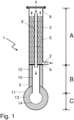
- inventive reformer tube 1 is divided into sections A (reaction chamber), B (outlet chamber) and C (manifold).
- Desulfurized natural gas together with reforming steam, enters the reaction chamber A arranged in the upper part of a casing tube 3 via an inlet line 2 .
- the jacket tube consists of a nickel-chromium steel, for example of the type G-X45NiCrNbTi3525.
- the inlet temperature of the feed gas is 600° C., and the space velocity, based on the catalyst volume, is typically 4000 to 5000 m N 3 /(m 3 h).
- the reformer tube is arranged in a vertical position with the open tube end of the casing tube 3 in the upper position and is heated from the outside by means of burners (not shown in 1 ).
- a closure device 4 for example a flanged-on cover, which can be opened for inspection processes and for filling or emptying the catalytic converter.
- the natural gas and the reforming steam After entering the jacket tube, the natural gas and the reforming steam enter a structured catalyst 5, which is composed of individual packing segments and, in terms of its structure, corresponds to that in FIG US 2012/0195801 A1 corresponds to the structured catalyst described. It has a specific surface area of 1100 m 2 /m 3 and is equipped with a nickel-containing active layer that is catalytically active for steam reforming.
- the structured catalyst is also designed such that a significant portion of the gas flow is deflected radially. As a result, part of the gas flow hits the inner wall of the reaction tube, which improves the radial heat transfer. However, the effect is limited, so that a further improvement in the radial heat transfer, as is achieved with the reformer tube according to the invention, is advantageous.
- the feeds then flow up through the structured catalyst where the endothermic steam reforming reaction takes place.
- the partially converted natural gas which also contains unreacted methane in addition to carbon oxides and hydrogen, enters a free space 8 after leaving the structured catalyst, which is attached to the closed one Pipe end 4 of the jacket pipe is arranged.
- the partially converted feed gas stream then enters the inlet end of a straight heat exchanger tube 9 which is arranged within the catalyst bed. The gas stream flowing through the heat exchanger tube 9 gives off part of its sensible heat in countercurrent to the catalyst bed and the feed gas stream flowing through it.
- the heat exchanger tubes are made of materials with good resistance to metal dusting corrosion such as Alloy 601, 602 CA, 617, 690, 692, 693, HR 160, HR 214, alloys containing copper or so-called multilayer materials in which the tubes are coated with tin Nickel or aluminium-nickel alloys are coated.
- the exit ends of the heat exchanger tube are provided with an anti-corrosion layer on the inside and on the parts that pass through the separating plate on the outside as well. In the present example, this is an aluminum diffusion layer.
- the synthesis gas product stream After passing through the heat exchanger tube, the synthesis gas product stream enters exit chamber B.
- the outlet end of the heat exchanger tube 9 is passed through a separating plate 6 and fixed in this way. It then opens out into an inner tube 10 on the outlet side, which represents the connection between the heat exchanger tube 9 and a collecting line 11 .
- the inner tube is also made from one of the above-mentioned metallic materials and its inner wall and preferably also its outer wall are equipped with an aluminum diffusion layer as an anti-corrosion layer.
- an inner tube made of a ceramic material can also be used.
- a gas-permeable insulating material 12 is attached between the outer wall of the inner tube and the inner wall of the jacket tube.
- Fiber-based insulating materials but also inherently dimensionally stable ceramic moldings can be used for this. The latter are particularly advantageous because they can be assembled and disassembled particularly easily. Due to their dimensional stability, they can be easily placed in the annular space between the jacket pipe and the inner pipe during assembly without the need for special fasteners.
- the inside of the collecting line 11 is provided with insulating material 13 and/or a corrosion-resistant, for example ceramic, coating 14 which has increased resistance to metal dusting corrosion.
- the synthesis gas product stream is discharged from the reformer tube 1 via the collecting line and is fed to further processing. Depending on the intended use of the synthesis gas product, this can include carbon monoxide conversion, gas scrubbing to remove carbon dioxide, pressure swing adsorption to remove hydrogen and other work-up stages.
- the examples according to the invention are based on configurations of the reformer with bayonet tubes with a structured catalyst.
- the steam export is between 0 and 0.8 kg of steam per m N 3 of hydrogen produced.
- the reforming temperature is above 900.degree.
- the reformer tubes should be equipped as normal tubes with a straight passage, ie without internal heat recovery, and with catalyst pellets or with a structured catalyst.
- the state of the art recommends, for example according to the patent publications EP 1944269 B1 or US7501078B2 , a design with a reduced number of reformer tubes to achieve savings.
- Embodiments of steam reforming processes according to the invention without steam export or with low steam export (0 to 0.3 kg export steam per m N 3 of hydrogen produced) have the following features, which aim to increase the reformer efficiency and the reforming temperature as much as possible:
- the tube diameter is reduced and the number of reformer tubes is increased in order to overcome mechanical limitations. This allows the reforming temperature to be increased beyond 900 °C.
- the reduction of the tube diameter is possible thanks to the use of the structured catalyst, which can be adapted to the small diameter and annulus.
- the increased reforming temperature shifts the reaction equilibrium in the direction of higher hydrocarbon conversion in the reformer, at the same time increasing the efficiency of the reformer (reformer efficiency) and reducing the total natural gas consumption, although the exchange area for heat exchange has decreased compared to the reference case in column 2.
- the cases shown in columns 2 and 3 are limited in terms of the maximum achievable reforming temperature due to the high tube thickness of the reformer tubes.
Abstract
Es wird ein Verfahren zum Herstellen von Synthesegas mit reduziertem Dampfexport durch katalytisches Dampfreformieren eines kohlenwasserstoffhaltigen Einsatzgases mit Dampf in einer Vielzahl von Reformerrohren in einem durch Brenner beheizten Reformerofen unter Bildung eines Dampfreformierungsrauchgases vorgeschlagen. Das Verfahren umfasst dabei eine Ausgestaltung der Reformerrohre als Reformerrohre mit internem Wärmeaustausch und die Verwendung eines strukturierten Katalysators. Für Exportdampfmengen zwischen 0 und 0,8 kg Exportdampf pro m<sub>N</sub><sup>3</sup> erzeugten Wasserstoffs wirken diese Merkmale in synergistischer Weise zusammen, wenn bestimmte Dampfreformierungsbedingungen ausgewählt werden.A method is proposed for producing synthesis gas with reduced steam export by catalytically steam reforming a hydrocarbonaceous feed gas with steam in a plurality of reformer tubes in a burner heated reformer furnace to form a steam reforming flue gas. The method includes an embodiment of the reformer tubes as reformer tubes with internal heat exchange and the use of a structured catalyst. For export steam amounts between 0 and 0.8 kg of export steam per m<sub>N</sub><sup>3</sup> of hydrogen produced, these features work together in a synergistic way when certain steam reforming conditions are selected.
Description
Die Erfindung betrifft ein Verfahren zum Herstellen eines Wasserstoff und Kohlenoxide enthaltenden Synthesegases mit reduziertem Dampfexport durch katalytisches Dampfreformieren eines kohlenwasserstoffhaltigen Einsatzgases, bevorzugt Erdgas, mit Dampf unter Dampfreformierungsbedingungen in einer Vielzahl von Reformerrohren in einem durch Brenner beheizten Reformerofen unter Bildung eines Dampfreformierungsrauchgases.The invention relates to a method for producing a synthesis gas containing hydrogen and carbon oxides with reduced steam export by catalytic steam reforming of a hydrocarbon-containing feed gas, preferably natural gas, with steam under steam reforming conditions in a plurality of reformer tubes in a burner-heated reformer furnace to form a steam reforming flue gas.
Kohlenwasserstoffe können mit Dampf katalytisch zu Synthesegas, also Mischungen von Wasserstoff (H2) und Kohlenmonoxid (CO), umgesetzt werden. Wie in
Die Dampfreformierung von Erdgas verläuft stark endotherm. Sie wird daher in einem Reformerofen durchgeführt, in dem zahlreiche, Katalysator enthaltende Reformerrohre parallel angeordnet sind, in denen die Dampfreformierungsreaktion abläuft. Die Außenwände des Reformerofens sowie seine Decke und sein Boden sind dabei mit mehreren Schichten aus feuerfestem Material ausgekleidet oder zugestellt, das Temperaturen bis zu 1200 °C standhält. Die Reformerrohre werden zumeist mittels Brennern befeuert, die an der Oberseite oder Unterseite oder an den Seitenwänden des Reformerofens angebracht sind und direkt den Zwischenraum zwischen den Reformerrohren befeuern. Dabei erfolgt der Wärmeübergang auf die Reformerrohre durch Wärmestrahlung und konvektive Wärmeübertragung von den heißen Rauchgasen.The steam reforming of natural gas is highly endothermic. It is therefore carried out in a reformer furnace in which numerous reformer tubes containing catalyst are arranged in parallel, in which the steam reforming reaction takes place. The outer walls of the reformer furnace, as well as its ceiling and floor, are lined or lined with several layers of refractory material that can withstand temperatures of up to 1200 °C. The reformer tubes are mostly fired by means of burners which are attached to the top or bottom or to the side walls of the reformer furnace and directly fire the space between the reformer tubes. The heat is transferred to the reformer tubes by thermal radiation and convective heat transfer from the hot flue gases.
Nach Vorerhitzung durch Wärmetauscher oder befeuerte Heizer auf mindestens ca. 500 °C tritt das Kohlenwasserstoff-Dampf-Gemisch nach Enderhitzung auf ca. 500 bis 1000 °C in die Reformerrohre ein und wird dort am Reformierungskatalysator zu Kohlenmonoxid und Wasserstoff umgesetzt. Verbreitet sind Reformierungskatalysatoren auf Nickelbasis. Während höhere Kohlenwasserstoffe vollständig zu Kohlenmonoxid und Wasserstoff umgesetzt werden, erfolgt im Falle des Methans üblicherweise ein Teilumsatz. Die Zusammensetzung des Produktgases wird dabei vom Reaktionsgleichgewicht bestimmt; das Produktgas enthält daher neben Kohlenmonoxid und Wasserstoff auch noch Kohlendioxid, nicht umgesetztes Methan sowie Wasserdampf. Zur Energieoptimierung oder bei Einsatzstoffen mit höheren Kohlenwasserstoffen kann nach dem Vorerhitzer ein sogenannter Prereformer zur Vorspaltung bzw. Vorreformierung des Einsatzstoffes eingesetzt werden. Der vorgespaltene Einsatzstoff wird dann in einem weiteren Erhitzer auf die gewünschte Reformerrohreintrittstemperatur erhitzt.After preheating by heat exchangers or fired heaters to at least approx. 500 °C, the hydrocarbon-steam mixture enters the reformer tubes after final heating to approx. 500 to 1000 °C and is converted there to carbon monoxide and hydrogen at the reforming catalyst. Nickel-based reforming catalysts are widespread. While higher hydrocarbons are completely converted into carbon monoxide and hydrogen, in the case of methane, partial conversion usually takes place. The composition of the product gas is determined by the reaction equilibrium; the product gas therefore contains not only carbon monoxide and hydrogen but also carbon dioxide, unreacted methane and water vapour. For energy optimization or in the case of feedstocks with higher hydrocarbons, a so-called pre-reformer can be used after the preheater for pre-splitting or pre-reforming of the feedstock. The pre-split feedstock is then heated in another heater to the desired reformer tube inlet temperature.
Das heiße Synthesegas-Produktgas wird nach Verlassen des Reformerofens in einem oder mehreren Wärmetauschern teilabgekühlt. Das teilabgekühlte Synthesegas-Produktgas durchläuft anschließend noch weitere Konditionierungsschritte, die von der Art des gewünschten Produktes oder des nachgeschalteten Verfahrens anhängig sind.After leaving the reformer furnace, the hot synthesis gas product gas is partially cooled in one or more heat exchangers. The partially cooled synthesis gas product gas then runs through further conditioning steps that depend on the type of product desired or the downstream process.
Die Dampfreformierung von Erdgas zeichnet sich durch ihren hohen Energiebedarf aus. Im Stand der Technik finden sich daher bereits Vorschläge, bei denen durch optimierte Verfahrensgestaltung, beispielsweise durch Energierückgewinnung, versucht werden soll, den Bedarf an Fremdenergie zu minimieren. So wurde von Higman bei der EURO-GAS-90-Konferenz, Trondheim, Juni 1990, veröffentlicht auch unter http://www.higman.de/gasification/papers/eurogas.pdf (Abruf am 27.09.2011), ein sogenanntes HCT-Reformerrohr mit internem Wärmeaustausch vorgestellt. Dieses umfasst ein äußeres, mit Katalysator gefülltes und von außen beheiztes Reformerrohr, bei dem das Katalysatorbett von dem Einsatzgas von oben nach unten durchströmt wird. Im Inneren des Katalysatorbettes befinden sich zwei gewendelte, als Doppelhelix angeordnete Wärmetauscherrohre aus einem geeigneten Material, durch die das teilreformierte Gas nach Verlassen des Katalysatorbettes strömt und dabei einen Teil seiner fühlbaren Wärme an den am Katalysator ablaufenden Dampfreformierungsprozess abgibt. Nachteilig ist hierbei allerdings der höhere Druckverlust aufgrund der längeren Leitungsstrecke des Gases durch die wendelförmig ausgestalteten Wärmetauscherrohre. Ein auf dieser Grundlage weiterentwickeltes Reformerrohr mit internem Wärmeaustausch wird auch in der internationalen Patentanmeldung
Bei der Weiterentwicklung der Dampfreformierungstechnologie besteht neben der Optimierung des Wärmehaushalts des Reformerrohrs eine weitere Zielrichtung in der Minimierung des Druckverlusts, die aufgrund der Reduzierung der benötigten Verdichtungsarbeit wirtschaftliche Vorteile erbringt.In the further development of steam reforming technology, in addition to optimizing the heat balance of the reformer tube, another goal is minimizing the pressure loss, which brings economic advantages due to the reduction in the required compression work.
Diese beiden Themengebiete wirken insofern zusammen, da konstruktive Maßnahmen, die auf die Verbesserung des Wärmehaushalts im Reformerrohr abzielen, oftmals den Druckverlust über das Reformerrohr in unerwünschter Weise erhöhen. Soll der Gesamtdruckverlust über das Reformerrohr daher konstant gehalten oder sogar reduziert werden, verbleibt als wesentliche Einflussgröße eine Reduzierung des Druckverlustes über den vorhandenen Reformierungskatalysator.These two subject areas interact to the extent that constructive measures aimed at improving the heat balance in the reformer tube often increase the pressure drop across the reformer tube in an undesirable manner. If the total pressure loss over the reformer tube is to be kept constant or even reduced, a reduction in the pressure loss over the existing reforming catalyst remains as a significant influencing variable.
Eine Möglichkeit zur Reduzierung des Druckverlustes über den Reformierungskatalysator besteht in der Verwendung strukturierter Katalysatoren, beispielsweise in Form strukturierter Packungen, die einen Reformierungskatalysator enthalten, wodurch strukturierte Katalysatoren entstehen. Unter einer strukturierten Packung versteht der Fachmann - in Abgrenzung von unstrukturierten Packungen bzw. Partikelschüttungen - speziell entworfene Behältereinbauten, wie sie beispielsweise in Absorberkolonnen, Destillationskolonnen und Festbettreaktoren eingesetzt werden. Eine strukturierte Packung besteht oft aus dünnen, gewellten und gelochten Metallplatten bzw. Drahtnetzen. Ferner können keramische Körper hergestellt werden, die dann als Wabenkörper oder Honeycombs bezeichnet werden. Das Design der strukturierten Packungen soll ihre spezifische Oberfläche maximieren und somit einen optimalen Austausch zwischen den unterschiedlichen Phasen bei minimalem Druckwiderstand oder Druckverlust gewährleisten. Bei einer heterogen katalysierten Reaktion wie der Dampfreformierung soll mithin die Austauschfläche zwischen dem strukturierten Katalysator und der Gasphase maximiert werden. Unter einem strukturiertem Katalysator wird demgemäß eine strukturierte Packung verstanden, die einen Katalysator enthält, indem dieser beispielsweise als Beschichtung auf die Oberfläche der strukturierten Packung aufgebracht oder in Form kleiner Partikel in die Strukturelemente der strukturierten Packung eingebettet wird.One way to reduce the pressure drop across the reforming catalyst is to use structured catalysts, for example in the form of structured packings containing a reforming catalyst, resulting in structured catalysts. The person skilled in the art understands structured packing to be - in Differentiation from unstructured packings or particle beds - specially designed vessel installations, such as those used in absorber columns, distillation columns and fixed-bed reactors. Structured packing often consists of thin, corrugated and perforated metal plates or wire mesh. Furthermore, ceramic bodies can be produced, which are then referred to as honeycomb bodies or honeycombs. The structured packings are designed to maximize their specific surface area and thus ensure optimal exchange between the different phases with minimal pressure resistance or pressure loss. In a heterogeneously catalyzed reaction such as steam reforming, the exchange surface between the structured catalyst and the gas phase should therefore be maximized. A structured catalyst is accordingly understood to mean a structured packing which contains a catalyst, for example by applying it as a coating to the surface of the structured packing or embedding it in the form of small particles in the structural elements of the structured packing.
Die Verwendung strukturierter Katalysatoren für die Dampfreformierung von Kohlenwasserstoffen ist an sich bekannt und wird beispielsweise in den Patentveröffentlichungen
Die US-Patentanmeldung
Bei endothermen Prozessen sind strukturierte Katalysatoren dafür bekannt, dass sie im Vergleich zu herkömmlichen Katalysatorpellets mehrere Vorteile bieten. Strukturierte Katalysatoren weisen einen höheren Wärmeübergangskoeffizienten und eine größere geometrische Oberfläche auf als Katalysatorpellets. Beides führt zu einer verbesserten Reaktionskinetik und höheren Umsatzraten für ein gegebenes Katalysatorvolumen. Außerdem weisen strukturierte Katalysatoren einen höheren Hohlraumanteil auf, was zu einem geringeren Druckabfall bei einem gegebenen Massenstrom führt.In endothermic processes, structured catalysts are known to offer several advantages compared to traditional catalyst pellets. Structured catalysts have a higher heat transfer coefficient and a larger geometric surface area than catalyst pellets. Both lead to improved reaction kinetics and higher turnover rates for a given catalyst volume. In addition, structured catalysts have a higher void fraction, which results in a lower pressure drop at a given mass flow rate.
Bei der Reformierung von Methan mit Dampf oder Kohlendioxid kann die Verwendung eines strukturierten Katalysators den internen Wärmeübergang von der Innenwand des Reformerrohrs auf das Prozessgas auf zwei Arten verbessern. Erstens erhöht der hohe intrinsische Wärmeübergangskoeffizient des strukturierten Katalysators die dem Prozessfluid zugeführte Wärmemenge und damit die Reaktionsgeschwindigkeit und den Umwandlungsgrad. Zweitens ermöglicht der geringe Druckabfall des strukturierten Katalysators höhere Durchflussraten. Da der interne Wärmeübergang auch durch Konvektion angetrieben wird, ist es daher von Interesse, den Massenstrom so weit wie möglich zu erhöhen.When reforming methane with steam or carbon dioxide, the use of a structured catalyst can improve the internal heat transfer from the inner wall of the reformer tube to the process gas in two ways. First, the high intrinsic heat transfer coefficient of the structured catalyst increases the amount of heat transferred to the process fluid and hence the reaction rate and degree of conversion. Second, the low pressure drop of the structured catalyst enables higher flow rates. Since the internal heat transfer is also driven by convection, it is therefore of interest to increase the mass flow as much as possible.
Eine Erhöhung des Massenstroms bedeutet auch eine Verringerung der Verweilzeit, mit der Folge, dass die Methanumsetzung beeinträchtigt werden könnte. Strukturierte Katalysatoren weisen jedoch eine viel größere verfügbare Oberfläche für die Reaktion auf, was die verringerte Verweilzeit bei höheren Flussraten ausgleicht.An increase in mass flow also means a reduction in residence time, with the result that methane conversion could be impaired. However, structured catalysts have a much larger available surface area for reaction, which offsets the reduced residence time at higher flow rates.
Ähnlich wie bei einem Aufbau mit Rohren mit Rippen kann ein Dampf-Methan-Reformer mit strukturiertem Katalysator Vorteile durch einen höheren Reformerwirkungsgrad bringen, um den Erdgasverbrauch zu senken, oder durch die Reduzierung der Anzahl der Rohre, um Einsparungen bei den Investitionskosten zu erzielen, wie in
In
In der
Die Verwendung strukturierter Katalysatoren statt von Schüttungen fester Katalysatorpartikel eröffnet demnach Möglichkeiten zur weiteren Optimierung des Dampfreformierungsverfahrens, insbesondere für besondere Betriebsweisen wie der Erzeugung begrenzter Mengen von Exportdampf. Dampfreformierungsanlagen erzeugen in effizienter Weise zwei Hauptprodukte, nämlich Synthesegas und einen unter Umständen aus mehreren Teildampfströmen bestehenden Produktdampfstrom, der ganz oder teilweise als Exportdampf abgegeben wird. Dabei sind die Verbraucher des Synthesegas-Produktes oft nicht identisch mit den Abnehmern des Exportdampfes. Nachteilig ist dabei, dass daher Diskrepanzen zwischen der Synthesegas-Produktion und der Abnahme des Exportdampfes auftreten können, da die Produktionsraten der beiden Produkte Synthesegas und Produktdampf aneinander gekoppelt sind und die Produktionsrate des Exportdampfes nur in sehr geringem Maße angepasst werden kann. Es besteht daher weiterer Bedarf an Dampfreformierungsverfahren, die es ermöglichen, die Produktionsraten von Synthesegas und von Dampf voneinander zu entkoppeln, wobei die vorteilhaften Eigenschaften strukturierter Katalysatoren genutzt werden sollen.The use of structured catalysts instead of beds of solid catalyst particles therefore opens up possibilities for further optimization of the steam reforming process, in particular for special operating modes such as the generation of limited amounts of export steam. Steam reforming plants efficiently produce two main products, namely synthesis gas and a product steam stream, which may consist of several partial steam streams, which is discharged in whole or in part as export steam. The consumers of the synthesis gas product are often not identical with the buyers of the export steam. The disadvantage here is that discrepancies can therefore arise between the synthesis gas production and the purchase of the export steam, since the production rates of the two products, synthesis gas and product steam, are coupled to one another and the production rate of the export steam can only be adjusted to a very small extent. There is therefore a further need for steam reforming processes that enable the production rates of synthesis gas and steam to be decoupled from one another while taking advantage of the advantageous properties of structured catalysts.
Die Aufgabe der vorliegenden Erfindung besteht daher darin, ein Verfahren zur Dampfreformierung von Kohlenwasserstoffen mit variablem, insbesondere mit reduziertem Dampfexport anzugeben, das die Eigenschaften strukturierter Katalysatoren nutzt, die insbesondere in Reformerrohren mit internem Wärmeaustausch angeordnet sind.The object of the present invention is therefore to specify a method for the steam reforming of hydrocarbons with variable, in particular with reduced steam export, which uses the properties of structured catalysts which are arranged in particular in reformer tubes with internal heat exchange.
Diese Aufgabe wird in einem ersten Aspekt der Erfindung durch ein Verfahren mit den Merkmalen des Anspruchs 1 in allgemeiner Weise gelöst. Weitere Aspekte der Erfindung ergeben sich aus den Unteransprüchen. Mit den weiteren Aspekten der Erfindung wird die Erfindung in besonderer Weise, teilweise in bevorzugter Weise gelöst.In a first aspect of the invention, this object is achieved in a general manner by a method having the features of claim 1 . Further aspects of the invention result from the dependent claims. With the further aspects of the invention, the invention is solved in a special way, partially in a preferred way.
Unter Fluidverbindung zwischen zwei Bereichen des Reformerrohres wird dabei jegliche Art von Verbindung verstanden, die es ermöglicht, dass ein Fluid, beispielsweise der Einsatzgasstrom oder der Synthesegasproduktstrom, von dem einen zu dem anderen der beiden Bereiche strömen kann, unbeachtlich etwaiger zwischengeschalteter Bereiche oder Bauteile.Fluid connection between two sections of the reformer tube is understood to mean any type of connection that allows a fluid, for example the feed gas stream or the synthesis gas product stream, to flow from one to the other of the two sections, regardless of any intervening sections or components.
Mit Wärmeaustauschbeziehung ist die Möglichkeit des Wärmeaustauschs oder der Wärmeübertragung zwischen zwei Bereichen des Reformerrohres gemeint, wobei alle Mechanismen des Wärmeaustauschs oder der Wärmeübertragung wie Wärmeleitung, Wärmestrahlung oder konvektiver Wärmetransport zum Tragen kommen können.The heat exchange relationship means the possibility of heat exchange or heat transfer between two areas of the reformer tube, with all mechanisms of heat exchange or heat transfer such as heat conduction, heat radiation or convective heat transport being able to come into play.
Unter Dampfreformierungsbedingungen sind die dem Fachmann an sich bekannten Verfahrensbedingungen, insbesondere von Temperatur, Druck und Verweilzeit, zu verstehen, wie sie oben beispielhaft genannt und detailliert im einschlägigen Schrifttum erörtert werden und bei denen mindestens ein Teilumsatz, bevorzugt allerdings technisch relevante Umsätze der Edukte in Synthesegasprodukte wie CO und Wasserstoff erfolgt. Entsprechend wird unter einem für die Dampfreformierung aktiven Katalysator ein Katalysator verstanden, der unter Dampfreformierungsbedingungen eben solche Umsätze bewirkt.Steam reforming conditions are to be understood as meaning the process conditions known per se to those skilled in the art, in particular temperature, pressure and residence time, as mentioned above by way of example and discussed in detail in the relevant literature and in which at least a partial conversion, but preferably technically relevant conversions, of the starting materials into synthesis gas products such as CO and hydrogen. Correspondingly, a catalyst which is active for steam reforming is understood as meaning a catalyst which brings about precisely such conversions under steam reforming conditions.
Die Begriffe "strukturierte Packung" und "strukturierter Katalysator" sind dem Fachmann vertraut und werden im Schrifttum verwendet. Es wird hierzu beispielhaft auf den Aufsatz
Reformerrohre mit internem Wärmeaustausch sind im Rahmen der vorliegenden Erfindung so ausgestaltet, dass eine Rohr-in-Rohr-Anordnung vorliegt, bei der ein Innenrohr mit kleinerem Durchmesser (Wärmetauscherrohr) in einem äußeren Rohr (Mantelrohr) vorzugsweise zentral angeordnet ist. Der sich hierdurch ergebende Ringspalt wird mindestens teilweise mit Katalysator ausgefüllt, bei der vorliegenden Erfindung vorzugsweise mit strukturiertem Katalysator. Die Edukte der Dampfreformierung, also ein vorerhitzter, kohlenwasserstoffhaltiger Einsatzstrom und Dampf, treten über einen Gaseintritt am Mantelrohr in dieses ein und werden an dem im Ringspalt angeordneten Katalysator umgesetzt oder zumindest teilumgesetzt. Nach Verlassen des Katalysators durchströmt das gasförmige Rohprodukt der Dampfreformierung das Wärmetauscherrohr bevorzugt im Gegenstrom relativ zu der Gasströmung durch das Katalysatorbett. Wesentlich ist, dass hierbei ein Wärmeübergang des noch heißen Dampfreformierungs-Rohprodukts durch die Wand des Wärmetauscherrohrs auf den Katalysator und/oder den durch ihn strömenden Einsatzstrom bzw. bereits teilumgesetzten Gasstrom erfolgt. Hierdurch wird der Wärmehaushalt bereits innerhalb eines Reformerrohrs verbessert, so dass weniger Abwärme durch Dampferzeugung abgeführt werden muss.In the context of the present invention, reformer tubes with internal heat exchange are designed in such a way that there is a tube-in-tube arrangement in which an inner tube with a smaller diameter (heat exchanger tube) is preferably centrally arranged in an outer tube (jacket tube). The resulting annular gap is at least partially filled with catalyst, preferably with structured catalyst in the present invention. The educts of the steam reforming, ie a preheated feed stream containing hydrocarbons and steam, enter the casing tube via a gas inlet and are converted or at least partially converted on the catalyst arranged in the annular gap. After leaving the catalyst, the gaseous crude product of the steam reforming flows through the heat exchanger tube preferably in countercurrent relative to the gas flow through the catalyst bed. What is important is that heat is transferred from the still hot steam reforming crude product through the wall of the heat exchanger tube to the catalyst and/or the feed stream flowing through it or the gas stream that has already been partially converted. As a result, the heat balance is already improved within a reformer tube, so that less waste heat has to be dissipated through steam generation.
Durch das im Inneren des strukturierten Katalysators angeordnete Wärmetauscherrohr strömt das erzeugte Rohsynthesegasprodukt zum Gasaustritt und gibt dabei einen Teil seiner fühlbaren Wärme im Gegenstrom an den strukturierten Katalysator, den durch ihn strömenden Einsatzgasstrom und somit an den am Katalysator ablaufenden Dampfreformierungsprozess ab. Dies verbessert insbesondere den radialen Wärmetransport im Reformerrohr. In einem Beispiel kann das Wärmetauscherrohr gleichzeitig Stütz- und Tragefunktionen für den strukturierten Katalysator bzw. für die einzelnen Packungssegmente aufweisen.The raw synthesis gas product produced flows through the heat exchanger tube arranged inside the structured catalyst to the gas outlet and gives off part of its sensible heat in countercurrent to the structured catalyst, the feed gas stream flowing through it and thus to the steam reforming process taking place at the catalyst. In particular, this improves the radial heat transport in the reformer tube. In one example, the heat exchanger tube can simultaneously have supporting and carrying functions for the structured catalyst or for the individual packing segments.
Als alternative Bezeichnung für solche Reformerrohre mit internem Wärmeaustausch wird auch der Begriff des Bajonett-Reformerrohrs verwendet, insbesondere dann, wenn der Gaseintritt und Gasaustritt an demselben Rohrende angeordnet sind und das andere Rohrende verschlossen ist.The term bayonet reformer tube is also used as an alternative designation for such reformer tubes with internal heat exchange, in particular when the gas inlet and gas outlet are arranged at the same tube end and the other tube end is closed.
Unter einem Verfahren zum Herstellen eines Wasserstoff und Kohlenoxide enthaltenden Synthesegases mit variablem Dampfexport wird verstanden, dass die spezifische Exportdampfmenge, gemessen in kg Dampf pro mN 3 erzeugten Wasserstoffs, durch die erfindungsgemäßen Änderungen der Verfahrensbedingungen in beabsichtigter und reproduzierbarer Weise gegenüber einer nicht erfindungsgemäßen, herkömmlichen Betriebsweise des Verfahrens variiert wird. Insbesondere wird unter einem Verfahren zum Herstellen eines Wasserstoff und Kohlenoxide enthaltenden Synthesegases mit reduziertem Dampfexport verstanden, dass die spezifische Exportdampfmenge, gemessen in kg Dampf pro mN 3 erzeugten Wasserstoffs, durch die erfindungsgemäßen Änderungen der Verfahrensbedingungen in beabsichtigter und reproduzierbarer Weise gegenüber einer nicht erfindungsgemäßen, herkömmlichen Betriebsweise des Verfahrens vermindert wird.A process for producing a synthesis gas containing hydrogen and carbon oxides with variable steam export is understood to mean that the specific amount of export steam, measured in kg of steam per m N 3 of hydrogen produced, is increased by the changes in the process conditions according to the invention in an intended and reproducible manner compared to a non-inventive, conventional one Operation of the method is varied. In particular, a process for producing a synthesis gas containing hydrogen and carbon oxides with reduced steam export is understood to mean that the specific amount of export steam, measured in kg of steam per m N 3 of hydrogen produced, is increased in an intended and reproducible manner by the changes according to the invention in the process conditions compared to a non-inventive, conventional operation of the process is reduced.
Unter der Reformierungstemperatur Tref wird die Temperatur des Dampfreformierungs-Rohprodukts nach Austritt aus dem Katalysatorbett bzw. aus dem strukturieren Katalysator verstanden. Sie wird durch entsprechende, an diesem Ort angebrachte Temperaturmessvorrichtungen gemessen.The reforming temperature T ref is understood to mean the temperature of the crude steam reforming product after exiting the catalyst bed or the structured catalyst. It is measured by appropriate temperature measuring devices installed at this location.
Die normierte Raumgeschwindigkeit des Einsatzgasstroms am Eintritt in die Reformerrohre wird bezogen auf das Volumen des strukturierten Katalysators in der Einheit mN 3/(s*mKat 3) angegeben.The normalized space velocity of the feed gas stream at the entry into the reformer tubes is given in terms of the volume of the structured catalyst in the unit m N 3 /(s * m cat 3 ).
Unter der Reformereffizienz (synonym Reformerwirkungsgrad) wird der prozentuale Anteil der von den Brennern erzeugten Wärmemenge verstanden, die auf das Prozessgas übertragen wird.The reformer efficiency (synonymous with reformer efficiency) is the percentage of heat generated by the burners that is transferred to the process gas.
Der Erfindung liegt die Erkenntnis zugrunde, dass mit den allgemeinen und den besonderen Aspekten der Erfindung die zugrunde liegende Aufgabe vorteilhaft gelöst werden kann. Dabei wirken folgende Teilelemente bzw. Merkmale zusammen:
- (1) Die Ausgestaltung des Reformerrohrs als Reformerrohr mit internem Wärmeaustausch ermöglicht eine verbesserte Wärmenutzung bereits innerhalb eines Reformerrohrs verbessert, so dass weniger Abwärme durch Dampferzeugung abgeführt werden muss.
- (2) Die Verwendung eines strukturierten Katalysators ermöglicht höhere Gas-Strömungsgeschwindigkeiten durch das Reformerrohr und führt somit zu einem besseren Wärmeübergang von dem Dampfreformierungs-Rohproduktstrom auf den Katalysator und/oder den durch ihn strömenden Einsatzstrom bzw. bereits teilumgesetzten Gasstrom.
- (3) Für vorgegebene Zielbereiche der Exportdampfmenge, nämlich:
- Exportdampfmenge null,
- niedrige Exportdampfmenge, zwischen 0 und 0,3 kg Exportdampf pro mN 3 erzeugten Wasserstoffs,
- mittlere Exportdampfmenge,
zwischen 0,3und 0,8 kg Exportdampf pro mN 3 erzeugten Wasserstoffs,
- (1) The configuration of the reformer tube as a reformer tube with internal heat exchange enables improved heat utilization already within a reformer tube, so that less waste heat has to be dissipated by steam generation.
- (2) The use of a structured catalyst enables higher gas flow rates through the reformer tube and thus leads to better heat transfer from the steam reforming crude product stream to the catalyst and/or the feed stream flowing through it or the gas stream that has already been partially converted.
- (3) For given target ranges of export steam volume, namely:
- export vapor quantity zero,
- low amount of export steam, between 0 and 0.3 kg export steam per m N 3 of hydrogen produced,
- average amount of export steam, between 0.3 and 0.8 kg export steam per m N 3 of hydrogen produced,
In einem zweiten Aspekt der Erfindung ist das Verfahren dadurch gekennzeichnet, dass die Dampfreformierungsbedingungen eine Reformierungstemperatur Tref von mindestens 920 °C, ein Dampf-Kohlenstoff-Verhältnis S/C von höchstens 2,7 mol/mol und eine normierte Raumgeschwindigkeit des Einsatzgasstroms am Eintritt in die Reformerrohre zwischen 2,5 und 3,0 mN 3/(s*mKat 3) umfassen und dass die spezifische Exportdampfmenge null ist. Untersuchungen haben gezeigt, dass mit der Auswahl der genannten Dampfreformierungsbedingungen die Erfindung in besonderer Weise gelöst wird, so dass die Erzeugung von Exportdampf vollständig unterbunden werden kann.In a second aspect of the invention the process is characterized in that the steam reforming conditions include a reforming temperature T ref of at least 920°C, a steam to carbon ratio S/C of at most 2.7 mol/mol and a normalized space velocity of the feed gas stream at the inlet in the reformer tubes comprise between 2.5 and 3.0 m N 3 /(s * m cat 3 ) and that the specific export steam quantity is zero. Studies have shown that the selection of the steam reforming conditions mentioned solves the invention in a special way, so that the generation of export steam can be completely suppressed.
In einem dritten Aspekt der Erfindung ist das Verfahren dadurch gekennzeichnet, dass die Dampfreformierungsbedingungen eine Reformierungstemperatur Tref von mindestens 930 °C, ein Dampf-Kohlenstoff-Verhältnis S/C von höchstens 2,7 mol/mol, bevorzugt von höchstens 2,4 mol/mol und eine normierte Raumgeschwindigkeit des Einsatzgasstroms am Eintritt in die Reformerrohre zwischen 3,5 und 4,0 mN 3/(s*mKat 3) umfassen und dass die spezifische Exportdampfmenge zwischen 0 und 0,3 kg Dampf pro mN 3 erzeugten Wasserstoffs beträgt. Untersuchungen haben gezeigt, dass mit der Auswahl der genannten Dampfreformierungsbedingungen die Erfindung in besonderer Weise gelöst wird, so dass die Erzeugung einer niedrigen Exportdampfmenge ermöglicht wird.In a third aspect of the invention, the process is characterized in that the steam reforming conditions include a reforming temperature T ref of at least 930°C, a steam/carbon ratio S/C of at most 2.7 mol/mol, preferably at most 2.4 mol /mol and a normalized space velocity of the feed gas flow at the entry into the reformer tubes between 3.5 and 4.0 m N 3 /(s * m cat 3 ) and that the specific export steam quantity between 0 and 0.3 kg steam per m N 3 generated hydrogen is. Investigations have shown that the invention is solved in a special way with the selection of the mentioned steam reforming conditions, so that the generation of a small amount of export steam is made possible.
In einem vierten Aspekt der Erfindung ist das Verfahren dadurch gekennzeichnet, dass die Dampfreformierungsbedingungen eine Reformierungstemperatur Tref von mindestens 930 °C, ein Dampf-Kohlenstoff-Verhältnis S/C von höchstens 2,7 mol/mol, bevorzugt von höchstens 2,4 mol/mol, meist bevorzugt von höchstens 2,1 mol/mol und eine normierte Raumgeschwindigkeit des Einsatzgasstroms am Eintritt in die Reformerrohre zwischen 3,0 und 3,5 mN 3/(s*mKat 3) umfassen und dass die spezifische Exportdampfmenge zwischen 0,3 und 0,8 kg Dampf pro mN 3 erzeugten Wasserstoffs beträgt. Untersuchungen haben gezeigt, dass mit der Auswahl der genannten Dampfreformierungsbedingungen die Erfindung in besonderer Weise gelöst wird, so dass die Erzeugung einer mittleren Exportdampfmenge ermöglicht wird.In a fourth aspect of the invention, the method is characterized in that the steam reforming conditions include a reforming temperature T ref of at least 930°C, a steam-to-carbon ratio S/C of at most 2.7 mol/mol, preferably at most 2.4 mol / mol, most preferably not more than 2.1 mol / mol and a normalized space velocity of the feed gas stream at the entrance to the reformer tubes between 3.0 and 3.5 m N 3 / (s * m cat 3 ) and that the specific amount of export steam between 0.3 and 0.8 kg of steam per m N 3 of hydrogen produced. Investigations have shown that the selection of the steam reforming conditions mentioned solves the invention in a special way, so that the generation of an average amount of export steam is made possible.
In einem fünften Aspekt der Erfindung ist das Verfahren dadurch gekennzeichnet, dass das Mantelrohr und das Wärmetauscherrohr einen kreisförmigen Querschnitt und der strukturierten Katalysator einen kreisringförmigen Querschnitt hat und dass das Mantelrohr, der strukturierte Katalysator und das Wärmetauscherrohr koaxial und konzentrisch angeordnet sind, wobei der strukturierte Katalysator im Wesentlichen gasdicht abschließend zwischen der Innenwand des Mantelrohrs und der Außenwand des Wärmetauscherrohrs angeordnet ist, so dass Kurzschlussströmungen an der Innenwand des Mantelrohrs entlang und somit an der strukturierten Packung vorbei minimiert werden.In a fifth aspect of the invention, the method is characterized in that the jacket tube and the heat exchanger tube have a circular cross section and the structured catalyst has an annular cross section and that the jacket tube, the structured catalyst and the heat exchanger tube are arranged coaxially and concentrically, the structured catalyst is arranged in a substantially gas-tight manner between the inner wall of the jacket tube and the outer wall of the heat exchanger tube, so that short-circuit flows along the inner wall of the jacket tube and thus past the structured packing are minimized.
In einem sechsten Aspekt der Erfindung ist das Verfahren dadurch gekennzeichnet, dass die Wärmestromdichte zwischen der Außenwand und der Innenwand der Mantelrohre zwischen 50 und 200 kW/m2 beträgt, gemittelt über die Länge der Mantelrohre. Untersuchungen haben gezeigt, dass mit der Auswahl der genannten Wärmestromdichte die Erfindung in besonderer Weise gelöst wird, so dass die Erzeugung von Exportdampfmengen zwischen null und einem mittleren Bereich der Exportdampfmenge ermöglicht wird.In a sixth aspect of the invention, the method is characterized in that the heat flow density between the outer wall and the inner wall of the jacket tubes is between 50 and 200 kW/m 2 averaged over the length of the jacket pipes. Investigations have shown that the invention is solved in a special way with the selection of said heat flow density, so that the generation of export steam quantities between zero and a medium range of the export steam quantity is made possible.
In einem siebten Aspekt der Erfindung ist das Verfahren dadurch gekennzeichnet, dass der Eintritt für den Einsatzgasstrom und der Austritt für den Rohsynthesegasproduktstrom an demselben Ende des Mantelrohrs angeordnet sind. Es wird somit die sogenannte Bajonett-Bauweise der Reformerrohre erhalten. Dies erleichtert die Montage und Demontage der Reformerrohre in einem Reformerofen, da hierbei nur ein Ende bzw. eine Seite des Reformerofen zugänglich sein muss.In a seventh aspect of the invention, the process is characterized in that the inlet for the feed gas stream and the outlet for the raw synthesis gas product stream are located at the same end of the mandrel. The so-called bayonet design of the reformer tubes is thus obtained. This facilitates the assembly and disassembly of the reformer tubes in a reformer furnace, since only one end or one side of the reformer furnace needs to be accessible.
In einem achten Aspekt der Erfindung ist das Verfahren dadurch gekennzeichnet, dass die Reformerrohre auf einem Boden des Reformerofens stehend oder von einer Decke des Reformerofens hängend in dem Reformerofen angeordnet sind und das Ende des Mantelrohrs, an dem der Eintritt für den Einsatzgasstrom und der Austritt für den Rohsynthesegasproduktstrom angeordnet sind, aus dem Reformerofen herausragt, wobei das entgegengesetzte Ende des Mantelrohrs im Inneren des Reformerofens angeordnet ist. Dies ist besonders günstig, da auf diese Weise thermisch-mechanische Spannungen zwischen dem Eintritt für den Einsatzgasstrom und dem Austritt für den Synthesegasproduktstrom vermieden werden, die aufgrund der beträchtlichen Temperaturunterschiede bei den aus dem Stand der Technik bekannten Reformerrohren entstehen, bei denen jeweils das Eintrittsende und das Austrittsende aus dem Reformerofen herausragen. Bei letzteren werden daher aufwändige Maßnahmen, wie beispielsweise die Verwendung von Gegengewichtsystemen, Spannungskompensatoren (sog. Pigtails) oder von Seilzügen, eingesetzt, um die auftretenden Spannungen und deren negative Auswirkungen, beispielsweise eine Verformung des Reformerrohrs, zu kompensieren. Dies ist bei einer hängenden oder stehenden Anordnung des Reformerrohrs nicht mehr notwendig.In an eighth aspect of the invention, the method is characterized in that the reformer tubes are arranged standing on a floor of the reformer furnace or hanging from a ceiling of the reformer furnace in the reformer furnace and the end of the jacket tube at which the inlet for the feed gas stream and the outlet for located in the raw synthesis gas product stream, protrudes from the reformer furnace, with the opposite end of the mandrel located inside the reformer furnace. This is particularly favorable because in this way thermal-mechanical stresses between the inlet for the feed gas stream and the outlet for the synthesis gas product stream are avoided, which arise due to the considerable temperature differences in the reformer tubes known from the prior art, in which the inlet end and the outlet end sticking out of the reformer furnace. In the case of the latter, complex measures, such as the use of counterweight systems, tension compensators (so-called pigtails) or cable pulls, are therefore used in order to compensate for the tensions that occur and their negative effects, for example deformation of the reformer tube. This is no longer necessary with a hanging or standing arrangement of the reformer tube.
In einem neunten Aspekt der Erfindung ist das Verfahren dadurch gekennzeichnet, dass eine Vielzahl von Reformerrohren und Brennern in einem Innenraum des Reformerofens angeordnet sind und dass die Längsachsen der durch die Brenner erzeugten Flammen parallel zu den Längsachsen der Reformerrohre ausgerichtet sind, wobei die Brenner an der Decke des Reformerofens und/oder am Boden des Reformerofens angeordnet sind. Auf diese Weise kann sichergestellt werden, dass durch einen Brenner die um ihn angeordneten Reformerrohre gleichmäßig beheizt werden. Ferner wird den Reformerrohren durch die parallel verlaufenden Flammenachsen auf einer längeren Strecke Strahlungswärme zugeführt und eine lokale Überhitzung der Außenseiten der Reformerrohre vermieden.In a ninth aspect of the invention, the method is characterized in that a plurality of reformer tubes and burners are arranged in an inner space of the reformer furnace and that the longitudinal axes of the flames generated by the burners are aligned parallel to the longitudinal axes of the reformer tubes, the burners being arranged on the ceiling of the reformer furnace and/or on the bottom of the reformer furnace. In this way it can be ensured that the reformer tubes arranged around it are evenly heated by a burner. Furthermore, radiant heat is supplied to the reformer tubes over a longer distance by the parallel flame axes and local overheating of the outsides of the reformer tubes is avoided.
In einem zehnten Aspekt der Erfindung ist das Verfahren dadurch gekennzeichnet, dass das mindestens teilweise katalytische Umsetzen des Einsatzstoffes unter Dampfreformierungsbedingungen in den Reformerrohren zu dem Rohsynthesegasprodukt zu mindestens 50 % erfolgt, bezogen auf die im Einsatzstoff enthaltenen Kohlenwasserstoffe.In a tenth aspect of the invention, the method is characterized in that at least 50% of the feedstock is catalytically converted under steam reforming conditions in the reformer tubes to form the raw synthesis gas product, based on the hydrocarbons contained in the feedstock.
In einem elften Aspekt der Erfindung ist das Verfahren dadurch gekennzeichnet, dass mindestens eines der Reformerrohre mehr als eine Art eines strukturierten Katalysators enthält, wobei sich die Art des strukturierten Katalysators bezieht auf dessen materielle, strukturelle oder texturelle Beschaffenheit und/oder seine spezifische katalytische Aktivität. Vorteilhaft wäre beispielsweise eine Konfiguration mit einem strukturierten Katalysator mit höherem Wärmeübergangskoeffizient, aber auch höherem Druckverlust in der Nähe des Gaseintritts in das Reformerrohr und mit einem strukturierten Katalysator mit geringerem Wärmeübergangskoeffizient, aber auch geringerem Druckverlust in der Nähe des Gasaustritts aus dem Reformerrohr, da in der Nähe des Gasaustritts aus dem Reformerrohr die Temperaturen und die Gasvolumenströme höher sind als in der Nähe des Gaseintritts in das Reformerrohr. Somit wird ein günstiger Kompromiss zwischen hohem Wärmeübergang und niedrigem Druckverlust erhalten.In an eleventh aspect of the invention, the method is characterized in that at least one of the reformer tubes contains more than one type of structured catalyst, the type of structured catalyst referring to its physical, structural or textural nature and/or its specific catalytic activity. For example, a configuration with a structured catalyst with a higher heat transfer coefficient but also a higher pressure drop near the gas inlet into the reformer tube and with a structured catalyst with a lower heat transfer coefficient but also lower pressure drop near the gas outlet from the reformer tube would be advantageous, since in the Near the gas outlet from the reformer tube, the temperatures and the gas flow rates are higher than near the gas inlet into the reformer tube. A favorable compromise between high heat transfer and low pressure loss is thus obtained.
In einem zwölften Aspekt der Erfindung ist das Verfahren dadurch gekennzeichnet, dass der oder die strukturierten Katalysatoren mindestens ein Element umfassen, das ausgewählt ist aus der Gruppe:
- Strukturierte Packungen, Monolithe, Wabenkörper, offenzellige metallische, glasartige oder keramische Schäume, gestapelte Drahtnetze;
- wobei die Elemente jeweils katalytische Aktivität für die Dampfreformierung aufweisen.
- Structured packings, monoliths, honeycombs, open-cell metallic, glassy or ceramic foams, stacked wire mesh;
- the elements each having catalytic activity for steam reforming.
Bevorzugt wird dabei ein strukturierter Katalysator in Form einer strukturierten Packung. Diese Art von strukturiertem Katalysator bietet gute Wärmeübertragungs- und Druckverlusteigenschaften und kann so gestaltet werden, dass die Strömung bevorzugt auf die Innen- oder Außenwand des Reformerrohrs gerichtet wird, um die Wärmeübertragung weiter zu verbessern. Die Trägerstruktur des strukturierten Katalysators besteht in einem Beispiel aus metallischem Material, da hierdurch Vorteile hinsichtlich der gegenüber dem Mantelrohr gleichmäßigeren Wärmeausdehnung erhalten werden und thermisch-mechanische Spannungen zwischen Mantelrohr und strukturiertem Katalysator reduziert werden. Um die Korrosion der gasberührten Materialien mittels der Metal-Dusting-Korrosion möglichst gering zu halten, wird bevorzugt die Oberfläche der Teile der Anlage, die sich in dem für die Metal-Dusting-Korrosion kritischen Arbeitsbereich, beispielsweise im Temperaturbereich zwischen 400 und 800 °C befinden, mit einem Korrosionsschutz, beispielsweise einer Aluminiumschicht versehen. Erfahrungsgemäß sind dies im Wesentlichen die Bereiche zwischen (in Strömungsrichtung) dem Innenrohr des Reformerrohrs und dem Abhitzekessel zur Dampferzeugung.A structured catalyst in the form of a structured packing is preferred. This type of structured catalyst offers good heat transfer and pressure drop characteristics and can be designed to preferentially direct the flow toward the inner or outer wall of the reformer tube to further enhance heat transfer. In one example, the support structure of the structured catalyst consists of metallic material, since this provides advantages in terms of the more uniform thermal expansion compared to the jacket tube and thermal-mechanical stresses between the jacket tube and the structured catalyst are reduced. In order to keep the corrosion of the materials in contact with the gas by means of metal dusting corrosion as low as possible, preference is given to the surface of the parts of the system that are in the working area critical for metal dusting corrosion, for example in the temperature range between 400 and 800 °C are provided with a corrosion protection, such as an aluminum layer. Experience has shown that these are essentially the areas between (in flow direction) the inner tube of the reformer tube and the waste heat boiler for steam generation.
Weiterbildungen, Vorteile und Anwendungsmöglichkeiten der Erfindung ergeben sich auch aus der nachfolgenden Beschreibung von Ausführungs- und Zahlenbeispielen und der Zeichnungen. Dabei bilden alle beschriebenen und/oder bildlich dargestellten Merkmale für sich oder in beliebiger Kombination die Erfindung, unabhängig von ihrer Zusammenfassung in den Ansprüchen oder deren Rückbeziehung.Further developments, advantages and possible applications of the invention also result from the following description of exemplary embodiments and numerical examples and the drawings. All of the features described and/or illustrated form the invention, either alone or in any combination, regardless of how they are summarized in the claims or how they relate back to them.
Es zeigt die einzige Figur:
- Fig. 1
- eine beispielhafte Ausgestaltung eines Reformerrohrs mit internem Wärmeaustausch und strukturiertem Katalysator zur Durchführung des erfindungsgemäßen Verfahrens.
- 1
- an exemplary embodiment of a reformer tube with internal heat exchange and structured catalyst for carrying out the method according to the invention.
Das in
Über eine Eintrittsleitung 2 tritt entschwefeltes Erdgas gemeinsam mit Reformierungsdampf in die im oberen Teil eines Mantelrohrs 3 angeordnete Reaktionskammer A ein. Das Mantelrohr besteht aus einem Nickel-Chrom-Stahl, beispielsweise des Typs G-X45NiCrNbTi3525. Die Eintrittstemperatur des Einsatzgases beträgt 600 °C, die auf das Katalysatorvolumen bezogene Raumgeschwindigkeit beträgt typischerweise 4000 bis 5000 mN 3/(m3 h).Desulfurized natural gas, together with reforming steam, enters the reaction chamber A arranged in the upper part of a
Im vorliegenden Ausführungsbeispiel ist das Reformerrohr senkrecht stehend mit dem offenen Rohrende des Mantelrohrs 3 in oberer Position angeordnet und wird von außen mittels Brennern beheizt (nicht dargestellt in
Das Erdgas und der Reformierungsdampf treten nach dem Eintritt in das Mantelrohr in einen strukturierten Katalysator 5 ein, der aus einzelnen Packungssegmenten zusammengesetzt ist und hinsichtlich seines Aufbaus dem in der
Die Einsatzstoffe strömen sodann aufwärts durch den strukturierten Katalysator, wobei die endotherme Dampfreformierungsreaktion stattfindet. Das teilumgesetzte Erdgas, das neben Kohlenoxiden und Wasserstoff auch noch nicht umgesetztes Methan enthält, tritt nach Verlassen des strukturierten Katalysators in einen Freiraum 8 ein, der an dem verschlossenen Rohrende 4 des Mantelrohres angeordnet ist. Anschließend tritt der teilumgesetzte Einsatzgasstrom in das Eintrittsende eines innerhalb der Katalysatorschüttung angeordneten, gerade verlaufenden Wärmetauscherrohrs 9 ein. Der durch das Wärmetauscherrohr 9 strömende Gasstrom gibt einen Teil seiner fühlbaren Wärme im Gegenstrom an die Katalysatorschüttung und den durch sie strömenden Einsatzgasstrom ab. Das Wärmetauscherrohr bestehen aus Werkstoffen mit guter Beständigkeit gegen die Metal Dusting-Korrosion wie z.B. Alloy 601, 602 CA, 617, 690, 692, 693, HR 160, HR 214, Kupfer enthaltende Legierungen oder sogenannte Mehrschichtmaterialien, bei denen die Rohre mit Zinn-Nickel- oder Aluminium-Nickel-Legierungen beschichtet sind. Alternativ oder zusätzlich sind die Austrittsenden des Wärmetauscherrohrs auf der Innenseite und an den durch den Trennboden durchgeführten Anteilen auch auf der Außenseite mit einer Korrosionsschutzschicht ausgestattet. Im vorliegenden Beispiel ist dies eine Aluminium-Diffusionsschicht.The feeds then flow up through the structured catalyst where the endothermic steam reforming reaction takes place. The partially converted natural gas, which also contains unreacted methane in addition to carbon oxides and hydrogen, enters a
Nach Durchströmen des Wärmetauscherrohrs tritt der Synthesegasproduktstrom in die Austrittskammer B ein. Dazu wird das Austrittsende des Wärmetauscherrohrs 9 durch einen Trennboden 6 durchgeführt und auf diese Weise fixiert. Es mündet dann austrittsseitig in ein Innenrohr 10 ein, das die Verbindung zwischen dem Wärmetauscherrohr 9 und einer Sammelleitung 11 darstellt. Das Innenrohr ist ebenfalls aus einem der oben genannten, metallischen Werkstoffe gefertigt und seine Innenwand und bevorzugt auch seine Außenwand mit einer Aluminium-Diffusionsschicht als Korrosionsschutzschicht ausgestattet. Alternativ kann auch ein aus einem keramischen Werkstoff hergestelltes Innenrohr verwendet werden.After passing through the heat exchanger tube, the synthesis gas product stream enters exit chamber B. For this purpose, the outlet end of the
Zwischen der Außenwand des Innenrohrs und der Innenwand des Mantelrohrs ist ein gasdurchlässiges Isoliermaterial 12 angebracht. Hierfür können faserbasierte Isoliermaterialien, aber auch in sich formstabile keramische Formkörper verwendet werden. Letztere sind besonders vorteilhaft, da sie besonders einfach montiert und demontiert werden können. Aufgrund ihrer Formstabilität können sie bei der Montage einfach in den Ringraum zwischen Mantelrohr und Innenrohr hineingestellt werden, ohne dass es besonderer Befestigungsmittel bedarf.A gas-permeable
Die Sammelleitung 11 ist auf ihrer Innenseite mit Isoliermaterial 13 und/oder einer korrosionsresistenten, beispielsweise keramischen Beschichtung 14 versehen, die eine erhöhte Beständigkeit gegen die Metal Dusting-Korrosion aufweisen. Über die Sammelleitung wird der Synthesegasproduktstrom aus dem Reformerrohr 1 ausgeleitet und wird der weiteren Aufarbeitung zugeführt. Diese kann je nach Verwendungszweck des Synthesegasproduktes eine Kohlenmonoxid-Konvertierung, eine Gaswäsche zur Abtrennung von Kohlendioxid, eine Druckwechseladsorption zur Wasserstoffabtrennung sowie weitere Aufarbeitungsstufen umfassen.The inside of the collecting
Den in den nachfolgenden Tabellen gezeigten Beispielen liegt eine gleiche Produktionskapazität an Wasserstoff und Dampf zugrunde. Alle Beispiele gehen von "End of Run"-Bedingungen (Ende eines Katalysatorzyklus) hinsichtlich der Katalysatoraktivität aus.The examples shown in the tables below are based on an equal production capacity of hydrogen and steam. All examples are based on "end of run" conditions (end of a catalyst cycle) in terms of catalyst activity.
Den erfindungsgemäßen Beispielen liegen Ausgestaltungen des Reformers mit Bajonettrohren mit strukturiertem Katalysator zugrunde. Der Dampfexport liegt zwischen 0 und 0,8 kg Dampf pro mN 3 erzeugten Wasserstoffs. Die Reformierungstemperatur liegt erfindungsgemäß oberhalb von 900 °C. Mit der Erfindung werden einige oder alle der folgenden Vorteile im Vergleich zu Verfahren gemäß Stand der Technik erhalten: Höherer Kohlenwasserstoff-Umsatz, höherer Reformerwirkungsgrad, geringerer Gesamt-Erdgas-Verbrauch, geringeres S/C-Verhältnis.The examples according to the invention are based on configurations of the reformer with bayonet tubes with a structured catalyst. The steam export is between 0 and 0.8 kg of steam per m N 3 of hydrogen produced. According to the invention, the reforming temperature is above 900.degree. Some or all of the following advantages are obtained with the invention compared to prior art processes: Higher hydrocarbon conversion, higher reformer efficiency, lower total natural gas consumption, lower S/C ratio.
Gemäß des Stands der Technik wird empfohlen, für Ausgestaltungen einer Reformeranlage mit Bajonettrohren und strukturiertem Katalysator eine reduzierte Anzahl von Reformerrohren vorzusehen, um die Investitionskosten zu senken.According to the prior art, it is recommended that a reduced number of reformer tubes be provided for configurations of a reformer system with bayonet tubes and structured catalyst, in order to reduce the investment costs.
Bei einer Reformeranlage ohne Dampfexport werden jedoch die Gesamt-Wasserstoff-Produktionskosten im Wesentlichen durch den Erdgasverbrauch dominiert, dagegen weniger durch die Investitionskosten. In Tabelle 1 werden daher für den Fall einer Reformeranlage ohne Dampfexport verschiedene Ausführungsformen mit Bajonettrohren verglichen.In a reformer plant without steam export, however, the total hydrogen production costs are essentially dominated by natural gas consumption, but less so through the investment costs. Table 1 therefore compares various embodiments with bayonet tubes for the case of a reformer system without steam export.
Die in Tabelle 1, Spalte 2 gezeigte Ausgestaltung zeigt ein Design gemäß Stand der Technik mit Bajonettrohren und Katalysatorpellets. Diese Ausgestaltung weist folgende Nachteile auf:
- (1) Um eine Fluidisierung zu verhindern, darf ein bestimmter Einsatzgas-Massenstrom nicht überschritten werden, was eine hohe Anzahl von Reformerrohren und/oder einen hohen Rohrdurchmesser erfordert. Damit steigt der Investitionsaufwand und der geringere Massenstrom pro Reformerrohr verringert den Wärmeübergangskoeffizienten.
- (2) Katalysatorpellet-Schüttungen erfordern ein Mindestverhältnis von Pellet-Durchmesser zu Ringraum, um eine akzeptable Bettporosität zu erhalten und einen Bypass am Katalysatorbett vorbei zu vermeiden. Dies führt zu einem höheren Rohrdurchmesser, der thermisch-mechanische Spannungen erhöht, so dass die maximal zulässige Rohrdicke bei einer niedrigeren Reformierungstemperatur erreicht wird, wodurch die Reformerleistungen, beispielweise der Kohlenwasserstoff-Umsatz oder die Reformereffizienz, begrenzt werden.
- (1) In order to prevent fluidization, a certain feed gas mass flow must not be exceeded, which requires a large number of reformer tubes and/or a large tube diameter. This increases the investment costs and the lower mass flow per reformer tube reduces the heat transfer coefficient.
- (2) Catalyst pellet beds require a minimum pellet diameter to annulus ratio to obtain acceptable bed porosity and avoid bypassing past the catalyst bed. This leads to a larger tube diameter, which increases thermal-mechanical stresses, so that the maximum allowable tube thickness is reached at a lower reforming temperature, thereby limiting the reformer performance, e.g. hydrocarbon conversion or reformer efficiency.
Die in Tabelle 1, Spalte 3 gezeigte Ausgestaltung beinhaltet Bajonettrohre mit strukturiertem Katalysator, in der vom Stand der Technik vorgeschlagenen Konfiguration mit weniger Rohren als im Fall der Spalte 2. Es werden jedoch verschiedene nachteilige Effekte beobachtet, wenn die Anzahl der Rohre verringert wird:
- (1) Der höhere Einsatzgas-Massenstrom pro Reformerrohr führt zu einer niedrigeren Verweilzeit, was durch die größere geometrische Oberfläche des strukturierten Katalysators etwas abgemildert wird. Die Annäherung an das Reaktionsgleichgewicht nimmt folglich zu, was zu einem höheren Erdgas-Verbrauch für eine gegebene Wasserstoff-Produktion führt.
- (2) Bei gegebener Reformerleistung und reduzierter Anzahl der Reformerrohre steigt die maximale Wandtemperatur, was sich negativ auf die Lebensdauer der Reformerrohre auswirken kann.
- (3) Die hohe maximale Wandtemperatur führt zu einer maximal zulässigen Rohrwandstärke, was eine weitere Erhöhung der Reformierungstemperatur ausschließt.
- (4) Die reduzierte Anzahl der Reformerrohre führt nicht zu signifikanten Einsparungen bei den Investitionskosten, da der strukturierte Katalysator im Vergleich zu Katalysatorpellets sehr teuer ist
- (1) The higher feed gas mass flow per reformer tube leads to a lower residence time, which is somewhat mitigated by the larger geometric surface area of the structured catalyst. The approach to reaction equilibrium consequently increases, leading to higher natural gas consumption for a given hydrogen production.
- (2) With a given reformer output and a reduced number of reformer tubes, the maximum wall temperature increases, which can have a negative effect on the service life of the reformer tubes.
- (3) The high maximum wall temperature leads to a maximum allowable tube wall thickness, which precludes a further increase in the reforming temperature.
- (4) The reduced number of reformer tubes does not result in significant capital cost savings because the structured catalyst is very expensive compared to catalyst pellets
Auch bei einer Reformeranlage mit niedrigem Dampfexport (0 bis 0,3 kg Exportdampf pro mN 3 erzeugten Wasserstoffs) werden die Gesamt-Wasserstoff-Produktionskosten im Wesentlichen durch den Erdgasverbrauch dominiert, dagegen weniger durch die Investitionskosten. In Tabelle 2 werden für den Fall einer Reformeranlage mit niedrigem Dampfexport verschiedene Ausführungsformen mit Bajonettrohren verglichen.Even in the case of a reformer plant with low steam export (0 to 0.3 kg of export steam per m N 3 of hydrogen produced), the total hydrogen production costs are essentially dominated by the natural gas consumption and less by the investment costs. Table 2 compares various embodiments with bayonet tubes for the case of a reformer system with low steam export.
Bei den in Tabelle 2, Spalte 2 und Spalte 3 gezeigten Fällen handelt es sich um Ausgestaltungen mit Katalysatorpellets bzw. mit strukturiertem Katalysator, wobei im Fall der Spalte 3 versucht wird, mit einer reduzierten Anzahl von Reformerrohren Einsparungen zu erzielen. Während die Investitionskosten in Ausgestaltungen mit niedrigem Dampfexport die Wirtschaftlichkeit etwas mehr beeinflussen als im Beispiel ohne Dampfexport, sind die Nachteile der in Spalte 2 und Spalte 3 gezeigten Fälle im Wesentlichen die gleichen wie in den Fällen der Tabelle 1, Spalte 2 und Spalte 3.The cases shown in Table 2,
Gemäß des Stands der Technik wird vorgeschlagen, bei einem Dampfreformierungsverfahren mit mittlerem Dampfexport die Reformerrohre als Normalrohre mit geradem Durchgang, also ohne interne Wärmerückgewinnung, und mit Katalysatorpellets oder mit strukturiertem Katalysator auszustatten. Im letzteren Fall empfiehlt der Stand der Technik, beispielsweise laut der Patentveröffentlichungen
Bei einer Anlage mit mittlerem Dampf-Export haben die Investitionskosten einen größeren Anteil an den Gesamtkosten für die Wasserstoff-Produktion als bei einem Szenario ohne Dampfexport oder mit niedrigem Dampfexport, aber die Gesamtwirtschaftlichkeit wird immer noch eindeutig durch den Erdgasverbrauch bestimmt.In a medium steam export plant, capital costs account for a larger proportion of the total cost of hydrogen production than in a no steam export or low steam export scenario, but the overall economics are still clearly determined by natural gas consumption.
In Tabelle 3 werden für den Fall einer Reformeranlage mit mittlerem Dampfexport verschiedene Ausführungsformen mit Normalrohren mit Pelletschüttung oder strukturiertem Katalysator und mit Bajonettrohren mit strukturiertem Katalysator verglichen. Dabei weist der in Spalte 2 gezeigte Fall folgende Limitierungen auf:
- (1) Aufgrund der begrenzten Reformereffizienz einer Ausgestaltung mit Normalrohren wird die angestrebte Exportdampfmenge bereits bei einer moderaten Reformierungstemperatur erreicht. Da andere Betriebsparameter, wie beispielweise die Verbrennungsluft-Vorwärmtemperatur, bereits an ihren jeweiligen oberen Grenzwerten angelangt sind, kann die Reformierungstemperatur nicht weiter erhöht werden, ohne mehr Dampf zu erzeugen, was den thermischen Gesamtwirkungsgrad des Reformierungsverfahrens verringern würde.
- (1) Due to the limited reformer efficiency of a design with normal tubes, the desired amount of export steam is already achieved at a moderate reforming temperature. Because other operating parameters, such as combustion air preheat temperature, are already at their respective upper limits, the reforming temperature cannot be increased further without producing more steam, which would reduce the overall thermal efficiency of the reforming process.
Der in Tabelle 3, Spalte 3 gezeigte Fall beinhaltet eine Ausgestaltung mit Normalrohren mit geradem Durchgang ohne Wärmerückgewinnung mit strukturiertem Katalysator und einer reduzierten Anzahl von Reformerrohren. Diese Ausgestaltung führt jedoch zu verschiedenen Nachteilen:
- (1) Die Reformierungstemperatur kann nicht erhöht werden, ohne überschüssigen Dampf zu erzeugen, wodurch der thermische Gesamtwirkungsgrad des Reformierungsverfahrens reduziert wird.
- (2) Die reduzierte Anzahl von Reformerrohren führt nicht zu signifikanten Einsparungen bei den Investitionskosten, da der strukturierte Katalysator im Vergleich zu Katalysatorpellets sehr teuer ist.
- (1) The reforming temperature cannot be increased without generating excess steam, thereby reducing the overall thermal efficiency of the reforming process.
- (2) The reduced number of reformer tubes does not lead to significant savings in capital costs because the structured catalyst is very expensive compared to catalyst pellets.
Erfindungsgemäße Ausgestaltungen von Dampfreformierungsverfahren ohne Dampfexport bzw. mit niedrigem Dampfexport (0 bis 0,3 kg Exportdampf pro mN 3 erzeugten Wasserstoffs) weisen die folgenden Merkmale auf, die darauf abzielen, die Reformereffizienz und die Reformierungstemperatur so weit wie möglich zu erhöhen:
In der in Tabelle 1 gezeigten, erfindungsgemäßen Ausgestaltung in Spalte 4 wird der Rohrdurchmesser verringert und die Anzahl der Reformerrohre erhöht, um mechanische Limitierungen zu überwinden. Dies erlaubt es, die Reformiertemperatur über 900 °C hinaus zu erhöhen. Die Verringerung des Rohrdurchmessers ist dank der Verwendung des strukturierten Katalysators möglich, der an den kleinen Durchmesser und Ringraum angepasst werden kann.Embodiments of steam reforming processes according to the invention without steam export or with low steam export (0 to 0.3 kg export steam per m N 3 of hydrogen produced) have the following features, which aim to increase the reformer efficiency and the reforming temperature as much as possible:
In the configuration according to the invention shown in Table 1 in
Die erhöhte Reformierungstemperatur verschiebt das Reaktionsgleichgewicht in Richtung eines höheren Kohlenwasserstoff-Umsatzes im Reformer, erhöht gleichzeitig den Wirkungsgrad des Reformers (Reformereffizienz) und reduziert den Gesamt-Erdgas-Verbrauch, obwohl die Austauschfläche für den Wärmeaustausch im Vergleich zum Referenzfall in Spalte 2 abgenommen hat. Die in den Spalten 2 und 3 gezeigten Fälle sind aufgrund der hohen Rohrdicke der Reformerrohre bezüglich der maximal erreichbaren Reformierungstemperatur eingeschränkt.The increased reforming temperature shifts the reaction equilibrium in the direction of higher hydrocarbon conversion in the reformer, at the same time increasing the efficiency of the reformer (reformer efficiency) and reducing the total natural gas consumption, although the exchange area for heat exchange has decreased compared to the reference case in
Bei erfindungsgemäßen Ausgestaltungen von Dampfreformierungsverfahren mit mittlerem Dampfexport (0,3 bis 0,8 kg Exportdampf pro mN 3 erzeugten Wasserstoffs) wäre es wenig praktikabel, ein Bajonettrohr mit Katalysatorpellets vorzusehen, da die Grenzwerte für verschiedene Verfahrensparameter bereits bei niedrigeren Dampfexportwerten erreicht würden. Dies gilt insbesondere für die Reformierungstemperatur, die ihrerseits durch die maximale Rohrwandstärke eingeschränkt ist. Durch die Verwendung strukturierten Katalysators können jedoch auch für mittleren Dampfexport Bajonettrohre statt Normalrohren verwendet werden, wodurch folgende Vorteile erzielt werden:
- (1) Die wesentlich höhere Reformierungstemperatur im erfindungsgemäßen
Fall der Tabelle 3,Spalte 4 führt zu einem höheren Kohlenwasserstoff-Umsatz, einer höheren Reformereffizienz und einem geringeren Gesamt-Erdgas-Verbrauch als in den Fällen mit Normalrohren,Spalten 2 und 3, ohne dass dank der internen Wärmerückgewinnung ein Überschuss an Dampf entsteht. - (2) Aufgrund der Nutzung der fühlbaren Wärme des erzeugten Rohsynthesegases kann dieser hohe Kohlenwasserstoff-Umsatz und eine höhere Reformereffizienz ohne Erhöhung des durchschnittlichen externen Wärmestroms von den Brennern auf die Reformerrohren und mit einer reduzierten Anzahl von Reformerrohren im Vergleich zu den in
den Tabelle 3,Spalten 2 und 3 gezeigten Fällen erreicht werden. - (3) Ferner kann hierdurch das S/C-Verhältnis bei der Dampfreformierung abgesenkt werden, was in Bezug auf Investitions- und Betriebskosten von Vorteil ist.
- (1) The significantly higher reforming temperature in the case of Table 3,
column 4 according to the invention leads to a higher hydrocarbon conversion, a higher reformer efficiency and a lower total natural gas consumption than in the cases with normal tubes,columns - (2) Due to the utilization of the sensible heat of the produced raw syngas, this high hydrocarbon conversion and higher reformer efficiency can be achieved without increasing the average external heat flow from the burners to the reformer tubes and with a reduced number of reformer tubes compared to those shown in Tables 3,
Columns - (3) This can also lower the S/C ratio in steam reforming, which is advantageous in terms of investment and running costs.
- [1][1]
- Reformerrohrreformer tube
- [2][2]
- Eintrittsleitungentry line
- [3][3]
- Mantelrohrcasing pipe
- [4][4]
- Verschlussvorrichtunglocking device
- [5][5]
- strukturierter Katalysatorstructured catalyst
- [6][6]
- Trennbodendivider
- [7][7]
- Katalysatorschüttungcatalyst bed
- [8][8th]
- Freiraumfree space
- [9][9]
- Wärmetauscherrohrheat exchanger tube
- [10][10]
- Innenrohrinner tube
- [11][11]
- Sammelleitungmanifold
- [12][12]
- Isolierschichtinsulating layer
- [13][13]
- Isolierschichtinsulating layer
- [14][14]
- Beschichtungcoating
- [A][a]
- Reaktionskammerreaction chamber
- [B][B]
- Austrittskammerexit chamber
- [C][c]
- Sammelleitungmanifold
Claims (12)
Priority Applications (5)
| Application Number | Priority Date | Filing Date | Title |
|---|---|---|---|
| EP21020475.6A EP4155259A1 (en) | 2021-09-22 | 2021-09-22 | Method for producing synthesis gas with reduced steam export |
| AU2022228210A AU2022228210A1 (en) | 2021-09-22 | 2022-09-09 | Process for producing synthesis gas with reduced steam export |
| KR1020220118401A KR20230042654A (en) | 2021-09-22 | 2022-09-20 | Process for producing synthesis gas with reduced steam export |
| CN202211142222.8A CN115888562A (en) | 2021-09-22 | 2022-09-20 | Process for producing syngas with reduced steam export |
| US17/949,410 US20230089656A1 (en) | 2021-09-22 | 2022-09-21 | Process for producing synthesis gas with reduced steam export |
Applications Claiming Priority (1)
| Application Number | Priority Date | Filing Date | Title |
|---|---|---|---|
| EP21020475.6A EP4155259A1 (en) | 2021-09-22 | 2021-09-22 | Method for producing synthesis gas with reduced steam export |
Publications (1)
| Publication Number | Publication Date |
|---|---|
| EP4155259A1 true EP4155259A1 (en) | 2023-03-29 |
Family
ID=77951433
Family Applications (1)
| Application Number | Title | Priority Date | Filing Date |
|---|---|---|---|
| EP21020475.6A Pending EP4155259A1 (en) | 2021-09-22 | 2021-09-22 | Method for producing synthesis gas with reduced steam export |
Country Status (5)
| Country | Link |
|---|---|
| US (1) | US20230089656A1 (en) |
| EP (1) | EP4155259A1 (en) |
| KR (1) | KR20230042654A (en) |
| CN (1) | CN115888562A (en) |
| AU (1) | AU2022228210A1 (en) |
Families Citing this family (3)
| Publication number | Priority date | Publication date | Assignee | Title |
|---|---|---|---|---|
| CN110121586B (en) | 2016-11-09 | 2022-01-25 | 八河流资产有限责任公司 | System and method for power production and integrated hydrogen production |
| WO2020250194A1 (en) | 2019-06-13 | 2020-12-17 | 8 Rivers Capital, Llc | Power production with cogeneration of further products |
| US11691874B2 (en) | 2021-11-18 | 2023-07-04 | 8 Rivers Capital, Llc | Apparatuses and methods for hydrogen production |
Citations (8)
| Publication number | Priority date | Publication date | Assignee | Title |
|---|---|---|---|---|
| EP0025308B1 (en) | 1979-09-06 | 1984-07-11 | Imperial Chemical Industries Plc | A process and apparatus for catalytically reacting steam with a hydrocarbon in endothermic conditions |
| EP0305203A2 (en) | 1987-08-27 | 1989-03-01 | Haldor Topsoe A/S | Method of carrying out heterogeneous catalytic chemical processes |
| EP0855366A1 (en) | 1997-01-22 | 1998-07-29 | Haldor Topsoe A/S | Synthesis gas production by steam reforming using catalyzed hardware |
| EP1857174A1 (en) | 2006-05-17 | 2007-11-21 | Air Products and Chemicals, Inc. | Reactor with expandable structure providing improved heat transfer |
| EP1944269A1 (en) | 2007-01-10 | 2008-07-16 | Air Products and Chemicals, Inc. | Process for generating synthesis gas using catalyzed structured packing |
| US20120195801A1 (en) | 2011-01-28 | 2012-08-02 | Catacel Corporation | Stackable structural reactors |
| WO2013068416A1 (en) | 2011-11-11 | 2013-05-16 | L'Air Liquide, Société Anonyme pour l'Etude et l'Exploitation des Procédés Georges Claude | Reformer tube having internal heat exchange |
| DE102016120167A1 (en) * | 2016-09-14 | 2018-03-15 | L'Air Liquide, Société Anonyme pour l'Etude et l'Exploitation des Procédés Georges Claude | Reformer tube with structured catalyst and improved heat balance |
-
2021
- 2021-09-22 EP EP21020475.6A patent/EP4155259A1/en active Pending
-
2022
- 2022-09-09 AU AU2022228210A patent/AU2022228210A1/en active Pending
- 2022-09-20 KR KR1020220118401A patent/KR20230042654A/en unknown
- 2022-09-20 CN CN202211142222.8A patent/CN115888562A/en active Pending
- 2022-09-21 US US17/949,410 patent/US20230089656A1/en active Pending
Patent Citations (11)
| Publication number | Priority date | Publication date | Assignee | Title |
|---|---|---|---|---|
| EP0025308B1 (en) | 1979-09-06 | 1984-07-11 | Imperial Chemical Industries Plc | A process and apparatus for catalytically reacting steam with a hydrocarbon in endothermic conditions |
| EP0305203A2 (en) | 1987-08-27 | 1989-03-01 | Haldor Topsoe A/S | Method of carrying out heterogeneous catalytic chemical processes |
| EP0855366A1 (en) | 1997-01-22 | 1998-07-29 | Haldor Topsoe A/S | Synthesis gas production by steam reforming using catalyzed hardware |
| EP1857174A1 (en) | 2006-05-17 | 2007-11-21 | Air Products and Chemicals, Inc. | Reactor with expandable structure providing improved heat transfer |
| EP1944269A1 (en) | 2007-01-10 | 2008-07-16 | Air Products and Chemicals, Inc. | Process for generating synthesis gas using catalyzed structured packing |
| US7501078B2 (en) | 2007-01-10 | 2009-03-10 | Air Products And Chemicals, Inc. | Process for generating synthesis gas using catalyzed structured packing |
| EP1944269B1 (en) | 2007-01-10 | 2010-09-01 | Air Products and Chemicals, Inc. | Process for generating synthesis gas using catalyzed structured packing |
| US20120195801A1 (en) | 2011-01-28 | 2012-08-02 | Catacel Corporation | Stackable structural reactors |
| WO2013068416A1 (en) | 2011-11-11 | 2013-05-16 | L'Air Liquide, Société Anonyme pour l'Etude et l'Exploitation des Procédés Georges Claude | Reformer tube having internal heat exchange |
| DE102011118217A1 (en) * | 2011-11-11 | 2013-05-16 | L'Air Liquide, Société Anonyme pour l'Etude et l'Exploitation des Procédés Georges Claude | Reformer tube with internal heat exchange |
| DE102016120167A1 (en) * | 2016-09-14 | 2018-03-15 | L'Air Liquide, Société Anonyme pour l'Etude et l'Exploitation des Procédés Georges Claude | Reformer tube with structured catalyst and improved heat balance |
Non-Patent Citations (2)
| Title |
|---|
| AUFSATZ VON M. GRÜNEWALDU. KUNZ: "Strukturierte Katalysatoren als Bausteine multifunktionaler Reaktoren", CHEMIE INGENIEUR TECHNIK, vol. 79, no. 9, 2007 |
| WIE, ULLMANN'S ENCYCLOPEDIA OF INDUSTRIAL CHEMISTRY, 1998 |
Also Published As
| Publication number | Publication date |
|---|---|
| AU2022228210A1 (en) | 2023-04-06 |
| US20230089656A1 (en) | 2023-03-23 |
| CN115888562A (en) | 2023-04-04 |
| KR20230042654A (en) | 2023-03-29 |
Similar Documents
| Publication | Publication Date | Title |
|---|---|---|
| EP3296255A1 (en) | Reformer tube with structured catalyst and improved temperature control | |
| EP4155259A1 (en) | Method for producing synthesis gas with reduced steam export | |
| EP2776365B1 (en) | Reformer tube having internal heat exchange | |
| EP3497058B1 (en) | Synthesis device and method for producing a product | |
| DE60216859T2 (en) | Methane steam reforming furnace with pre-reformer heated by convection | |
| DE69736438T2 (en) | METHOD FOR THE STEAM REFORMATION OF HYDROCARBONS | |
| EP3401299B1 (en) | Reactor for carrying out exothermic equilibrium reactions | |
| EP1425244B1 (en) | Compact reformer unit in the low performance range, for producing hydrogen from gaseous hydrocarbons | |
| DE112005000390T5 (en) | Integrated fuel processing plant for decentralized hydrogen production | |
| CN1196330A (en) | Synthesis gas production by steam reforming using catalyzed hardware | |
| EP0687648A1 (en) | Two stages methanol reforming | |
| WO2016207342A1 (en) | Optimization of the heat balance in reformers by using metal catalyst supports | |
| EP0787679A1 (en) | Process and apparatus for the recovery of a gas rich in hydrogen and poor in carbon monoxide | |
| EP3266739B1 (en) | Corrosion protected reformer tube with internal heat exchanger | |
| DE2929300A1 (en) | Reactor for heterogeneous catalyst gas phase reactions - is cross sectionally tailored to specific heat requirements in different reaction stages | |
| DE3832257A1 (en) | CATALYST FIXED BED REACTOR | |
| DE10333523B4 (en) | Heat exchanger arrangement for the transmission of reformate energy to steam and air | |
| EP3401300B1 (en) | Method for the production of methanol | |
| EP1427668A1 (en) | Device for the generation of hydrogen | |
| DE10345902B4 (en) | Production of synthesis gas from natural gas involves effecting both the reforming of a natural gas/steam mixture and also cooling of the obtained synthesis gas in a closed vertical reactor | |
| EP3135370B1 (en) | Reactor for the production of synthesis gas by steam reforming | |
| WO2013135668A1 (en) | Chemical reactor system, comprising an axial flow reactor with heating levels and intermediate levels | |
| WO1999044734A1 (en) | Apparatus with packing through which media flow and method for operating an apparatus of this kind | |
| DE10209886A1 (en) | Device and method for reforming hydrocarbons from a feed gas | |
| EP2379446A1 (en) | Method for producing syngas |
Legal Events
| Date | Code | Title | Description |
|---|---|---|---|
| PUAI | Public reference made under article 153(3) epc to a published international application that has entered the european phase |
Free format text: ORIGINAL CODE: 0009012 |
|
| STAA | Information on the status of an ep patent application or granted ep patent |
Free format text: STATUS: THE APPLICATION HAS BEEN PUBLISHED |
|
| AK | Designated contracting states |
Kind code of ref document: A1 Designated state(s): AL AT BE BG CH CY CZ DE DK EE ES FI FR GB GR HR HU IE IS IT LI LT LU LV MC MK MT NL NO PL PT RO RS SE SI SK SM TR |
|
| RAP3 | Party data changed (applicant data changed or rights of an application transferred) |
Owner name: L'AIR LIQUIDE, SOCIETE ANONYME POUR L'ETUDE ET L'EXPLOITATION DES PROCEDES GEORGES CLAUDE |
|
| STAA | Information on the status of an ep patent application or granted ep patent |
Free format text: STATUS: REQUEST FOR EXAMINATION WAS MADE |
|
| 17P | Request for examination filed |
Effective date: 20230929 |
|
| RBV | Designated contracting states (corrected) |
Designated state(s): AL AT BE BG CH CY CZ DE DK EE ES FI FR GB GR HR HU IE IS IT LI LT LU LV MC MK MT NL NO PL PT RO RS SE SI SK SM TR |