EP3401300B1 - Method for the production of methanol - Google Patents
Method for the production of methanol Download PDFInfo
- Publication number
- EP3401300B1 EP3401300B1 EP17400025.7A EP17400025A EP3401300B1 EP 3401300 B1 EP3401300 B1 EP 3401300B1 EP 17400025 A EP17400025 A EP 17400025A EP 3401300 B1 EP3401300 B1 EP 3401300B1
- Authority
- EP
- European Patent Office
- Prior art keywords
- reaction
- reactor
- synthesis gas
- cooling
- catalyst
- Prior art date
- Legal status (The legal status is an assumption and is not a legal conclusion. Google has not performed a legal analysis and makes no representation as to the accuracy of the status listed.)
- Active
Links
- OKKJLVBELUTLKV-UHFFFAOYSA-N Methanol Chemical compound OC OKKJLVBELUTLKV-UHFFFAOYSA-N 0.000 title claims description 198
- 238000000034 method Methods 0.000 title claims description 68
- 238000004519 manufacturing process Methods 0.000 title claims description 9
- 238000006243 chemical reaction Methods 0.000 claims description 208
- 239000007789 gas Substances 0.000 claims description 117
- 230000015572 biosynthetic process Effects 0.000 claims description 105
- 238000003786 synthesis reaction Methods 0.000 claims description 101
- 239000003054 catalyst Substances 0.000 claims description 88
- 238000001816 cooling Methods 0.000 claims description 58
- 230000008569 process Effects 0.000 claims description 53
- 239000000047 product Substances 0.000 claims description 49
- 239000000203 mixture Substances 0.000 claims description 36
- 238000010438 heat treatment Methods 0.000 claims description 30
- 239000012530 fluid Substances 0.000 claims description 21
- UGFAIRIUMAVXCW-UHFFFAOYSA-N Carbon monoxide Chemical class [O+]#[C-] UGFAIRIUMAVXCW-UHFFFAOYSA-N 0.000 claims description 18
- 239000002826 coolant Substances 0.000 claims description 17
- 229910052739 hydrogen Inorganic materials 0.000 claims description 16
- 239000007788 liquid Substances 0.000 claims description 16
- 229910002090 carbon oxide Inorganic materials 0.000 claims description 15
- 239000001257 hydrogen Substances 0.000 claims description 15
- 239000007795 chemical reaction product Substances 0.000 claims description 14
- 238000007599 discharging Methods 0.000 claims description 14
- UFHFLCQGNIYNRP-UHFFFAOYSA-N Hydrogen Chemical compound [H][H] UFHFLCQGNIYNRP-UHFFFAOYSA-N 0.000 claims description 13
- 238000011144 upstream manufacturing Methods 0.000 claims description 11
- XLYOFNOQVPJJNP-UHFFFAOYSA-N water Substances O XLYOFNOQVPJJNP-UHFFFAOYSA-N 0.000 claims description 11
- 238000009833 condensation Methods 0.000 claims description 10
- 230000005494 condensation Effects 0.000 claims description 10
- 230000007423 decrease Effects 0.000 claims description 9
- 238000000926 separation method Methods 0.000 claims description 8
- 238000001704 evaporation Methods 0.000 claims description 7
- 238000009835 boiling Methods 0.000 claims description 5
- 238000004064 recycling Methods 0.000 claims description 5
- 238000010626 work up procedure Methods 0.000 claims description 5
- 230000008020 evaporation Effects 0.000 claims description 3
- 238000000429 assembly Methods 0.000 claims description 2
- 230000000712 assembly Effects 0.000 claims description 2
- 238000012856 packing Methods 0.000 claims description 2
- 238000005191 phase separation Methods 0.000 claims description 2
- 230000008021 deposition Effects 0.000 claims 2
- 239000002199 base oil Substances 0.000 claims 1
- 238000012546 transfer Methods 0.000 description 26
- 239000012809 cooling fluid Substances 0.000 description 14
- 230000000052 comparative effect Effects 0.000 description 11
- 239000011261 inert gas Substances 0.000 description 10
- 230000000694 effects Effects 0.000 description 9
- 230000003197 catalytic effect Effects 0.000 description 8
- VNWKTOKETHGBQD-UHFFFAOYSA-N methane Chemical compound C VNWKTOKETHGBQD-UHFFFAOYSA-N 0.000 description 8
- 239000006227 byproduct Substances 0.000 description 7
- 229910002091 carbon monoxide Inorganic materials 0.000 description 7
- CURLTUGMZLYLDI-UHFFFAOYSA-N Carbon dioxide Chemical compound O=C=O CURLTUGMZLYLDI-UHFFFAOYSA-N 0.000 description 6
- 241000282326 Felis catus Species 0.000 description 6
- 238000010521 absorption reaction Methods 0.000 description 5
- 239000000376 reactant Substances 0.000 description 5
- IJGRMHOSHXDMSA-UHFFFAOYSA-N Atomic nitrogen Chemical compound N#N IJGRMHOSHXDMSA-UHFFFAOYSA-N 0.000 description 4
- RYGMFSIKBFXOCR-UHFFFAOYSA-N Copper Chemical compound [Cu] RYGMFSIKBFXOCR-UHFFFAOYSA-N 0.000 description 4
- 229910052802 copper Inorganic materials 0.000 description 4
- 239000010949 copper Substances 0.000 description 4
- 230000009849 deactivation Effects 0.000 description 4
- 230000017525 heat dissipation Effects 0.000 description 4
- 230000009467 reduction Effects 0.000 description 4
- 238000013459 approach Methods 0.000 description 3
- 229910002092 carbon dioxide Inorganic materials 0.000 description 3
- 230000008859 change Effects 0.000 description 3
- 238000002474 experimental method Methods 0.000 description 3
- 150000002431 hydrogen Chemical class 0.000 description 3
- 230000010354 integration Effects 0.000 description 3
- 230000007246 mechanism Effects 0.000 description 3
- 239000007858 starting material Substances 0.000 description 3
- 238000009825 accumulation Methods 0.000 description 2
- 239000001569 carbon dioxide Substances 0.000 description 2
- 238000007036 catalytic synthesis reaction Methods 0.000 description 2
- 230000006835 compression Effects 0.000 description 2
- 238000007906 compression Methods 0.000 description 2
- 238000013461 design Methods 0.000 description 2
- 239000008246 gaseous mixture Substances 0.000 description 2
- 239000000463 material Substances 0.000 description 2
- 229910052757 nitrogen Inorganic materials 0.000 description 2
- 239000002245 particle Substances 0.000 description 2
- 238000012545 processing Methods 0.000 description 2
- 239000012495 reaction gas Substances 0.000 description 2
- 239000011541 reaction mixture Substances 0.000 description 2
- 229920006395 saturated elastomer Polymers 0.000 description 2
- 239000011949 solid catalyst Substances 0.000 description 2
- 239000000126 substance Substances 0.000 description 2
- MHCVCKDNQYMGEX-UHFFFAOYSA-N 1,1'-biphenyl;phenoxybenzene Chemical compound C1=CC=CC=C1C1=CC=CC=C1.C=1C=CC=CC=1OC1=CC=CC=C1 MHCVCKDNQYMGEX-UHFFFAOYSA-N 0.000 description 1
- 230000006978 adaptation Effects 0.000 description 1
- 230000033228 biological regulation Effects 0.000 description 1
- 239000013590 bulk material Substances 0.000 description 1
- 229910052799 carbon Inorganic materials 0.000 description 1
- 239000000969 carrier Substances 0.000 description 1
- 238000004140 cleaning Methods 0.000 description 1
- 238000004891 communication Methods 0.000 description 1
- 239000000498 cooling water Substances 0.000 description 1
- 238000011161 development Methods 0.000 description 1
- 230000018109 developmental process Effects 0.000 description 1
- 238000004821 distillation Methods 0.000 description 1
- 238000009826 distribution Methods 0.000 description 1
- 238000011143 downstream manufacturing Methods 0.000 description 1
- 230000002349 favourable effect Effects 0.000 description 1
- 238000011049 filling Methods 0.000 description 1
- 238000010574 gas phase reaction Methods 0.000 description 1
- 238000002347 injection Methods 0.000 description 1
- 239000007924 injection Substances 0.000 description 1
- 238000007689 inspection Methods 0.000 description 1
- 239000012263 liquid product Substances 0.000 description 1
- 238000011068 loading method Methods 0.000 description 1
- 239000012528 membrane Substances 0.000 description 1
- 238000002156 mixing Methods 0.000 description 1
- 238000003541 multi-stage reaction Methods 0.000 description 1
- 238000005457 optimization Methods 0.000 description 1
- 231100000572 poisoning Toxicity 0.000 description 1
- 230000000607 poisoning effect Effects 0.000 description 1
- 230000008092 positive effect Effects 0.000 description 1
- 230000000750 progressive effect Effects 0.000 description 1
- 238000010926 purge Methods 0.000 description 1
- 230000005855 radiation Effects 0.000 description 1
- 230000001105 regulatory effect Effects 0.000 description 1
- 239000007787 solid Substances 0.000 description 1
- 239000000243 solution Substances 0.000 description 1
- 238000001179 sorption measurement Methods 0.000 description 1
- 230000007704 transition Effects 0.000 description 1
- 230000007306 turnover Effects 0.000 description 1
- 238000003466 welding Methods 0.000 description 1
Images


Classifications
-
- C—CHEMISTRY; METALLURGY
- C07—ORGANIC CHEMISTRY
- C07C—ACYCLIC OR CARBOCYCLIC COMPOUNDS
- C07C29/00—Preparation of compounds having hydroxy or O-metal groups bound to a carbon atom not belonging to a six-membered aromatic ring
- C07C29/15—Preparation of compounds having hydroxy or O-metal groups bound to a carbon atom not belonging to a six-membered aromatic ring by reduction of oxides of carbon exclusively
- C07C29/151—Preparation of compounds having hydroxy or O-metal groups bound to a carbon atom not belonging to a six-membered aromatic ring by reduction of oxides of carbon exclusively with hydrogen or hydrogen-containing gases
- C07C29/152—Preparation of compounds having hydroxy or O-metal groups bound to a carbon atom not belonging to a six-membered aromatic ring by reduction of oxides of carbon exclusively with hydrogen or hydrogen-containing gases characterised by the reactor used
-
- B—PERFORMING OPERATIONS; TRANSPORTING
- B01—PHYSICAL OR CHEMICAL PROCESSES OR APPARATUS IN GENERAL
- B01J—CHEMICAL OR PHYSICAL PROCESSES, e.g. CATALYSIS OR COLLOID CHEMISTRY; THEIR RELEVANT APPARATUS
- B01J8/00—Chemical or physical processes in general, conducted in the presence of fluids and solid particles; Apparatus for such processes
- B01J8/02—Chemical or physical processes in general, conducted in the presence of fluids and solid particles; Apparatus for such processes with stationary particles, e.g. in fixed beds
- B01J8/04—Chemical or physical processes in general, conducted in the presence of fluids and solid particles; Apparatus for such processes with stationary particles, e.g. in fixed beds the fluid passing successively through two or more beds
- B01J8/0403—Chemical or physical processes in general, conducted in the presence of fluids and solid particles; Apparatus for such processes with stationary particles, e.g. in fixed beds the fluid passing successively through two or more beds the fluid flow within the beds being predominantly horizontal
- B01J8/0423—Chemical or physical processes in general, conducted in the presence of fluids and solid particles; Apparatus for such processes with stationary particles, e.g. in fixed beds the fluid passing successively through two or more beds the fluid flow within the beds being predominantly horizontal through two or more otherwise shaped beds
- B01J8/0438—Chemical or physical processes in general, conducted in the presence of fluids and solid particles; Apparatus for such processes with stationary particles, e.g. in fixed beds the fluid passing successively through two or more beds the fluid flow within the beds being predominantly horizontal through two or more otherwise shaped beds the beds being placed next to each other
-
- B—PERFORMING OPERATIONS; TRANSPORTING
- B01—PHYSICAL OR CHEMICAL PROCESSES OR APPARATUS IN GENERAL
- B01J—CHEMICAL OR PHYSICAL PROCESSES, e.g. CATALYSIS OR COLLOID CHEMISTRY; THEIR RELEVANT APPARATUS
- B01J8/00—Chemical or physical processes in general, conducted in the presence of fluids and solid particles; Apparatus for such processes
- B01J8/02—Chemical or physical processes in general, conducted in the presence of fluids and solid particles; Apparatus for such processes with stationary particles, e.g. in fixed beds
- B01J8/04—Chemical or physical processes in general, conducted in the presence of fluids and solid particles; Apparatus for such processes with stationary particles, e.g. in fixed beds the fluid passing successively through two or more beds
- B01J8/0403—Chemical or physical processes in general, conducted in the presence of fluids and solid particles; Apparatus for such processes with stationary particles, e.g. in fixed beds the fluid passing successively through two or more beds the fluid flow within the beds being predominantly horizontal
- B01J8/0423—Chemical or physical processes in general, conducted in the presence of fluids and solid particles; Apparatus for such processes with stationary particles, e.g. in fixed beds the fluid passing successively through two or more beds the fluid flow within the beds being predominantly horizontal through two or more otherwise shaped beds
- B01J8/0442—Chemical or physical processes in general, conducted in the presence of fluids and solid particles; Apparatus for such processes with stationary particles, e.g. in fixed beds the fluid passing successively through two or more beds the fluid flow within the beds being predominantly horizontal through two or more otherwise shaped beds the beds being placed in separate reactors
-
- B—PERFORMING OPERATIONS; TRANSPORTING
- B01—PHYSICAL OR CHEMICAL PROCESSES OR APPARATUS IN GENERAL
- B01J—CHEMICAL OR PHYSICAL PROCESSES, e.g. CATALYSIS OR COLLOID CHEMISTRY; THEIR RELEVANT APPARATUS
- B01J8/00—Chemical or physical processes in general, conducted in the presence of fluids and solid particles; Apparatus for such processes
- B01J8/02—Chemical or physical processes in general, conducted in the presence of fluids and solid particles; Apparatus for such processes with stationary particles, e.g. in fixed beds
- B01J8/04—Chemical or physical processes in general, conducted in the presence of fluids and solid particles; Apparatus for such processes with stationary particles, e.g. in fixed beds the fluid passing successively through two or more beds
- B01J8/0446—Chemical or physical processes in general, conducted in the presence of fluids and solid particles; Apparatus for such processes with stationary particles, e.g. in fixed beds the fluid passing successively through two or more beds the flow within the beds being predominantly vertical
- B01J8/0449—Chemical or physical processes in general, conducted in the presence of fluids and solid particles; Apparatus for such processes with stationary particles, e.g. in fixed beds the fluid passing successively through two or more beds the flow within the beds being predominantly vertical in two or more cylindrical beds
- B01J8/0457—Chemical or physical processes in general, conducted in the presence of fluids and solid particles; Apparatus for such processes with stationary particles, e.g. in fixed beds the fluid passing successively through two or more beds the flow within the beds being predominantly vertical in two or more cylindrical beds the beds being placed in separate reactors
-
- B—PERFORMING OPERATIONS; TRANSPORTING
- B01—PHYSICAL OR CHEMICAL PROCESSES OR APPARATUS IN GENERAL
- B01J—CHEMICAL OR PHYSICAL PROCESSES, e.g. CATALYSIS OR COLLOID CHEMISTRY; THEIR RELEVANT APPARATUS
- B01J8/00—Chemical or physical processes in general, conducted in the presence of fluids and solid particles; Apparatus for such processes
- B01J8/02—Chemical or physical processes in general, conducted in the presence of fluids and solid particles; Apparatus for such processes with stationary particles, e.g. in fixed beds
- B01J8/04—Chemical or physical processes in general, conducted in the presence of fluids and solid particles; Apparatus for such processes with stationary particles, e.g. in fixed beds the fluid passing successively through two or more beds
- B01J8/0496—Heating or cooling the reactor
-
- B—PERFORMING OPERATIONS; TRANSPORTING
- B01—PHYSICAL OR CHEMICAL PROCESSES OR APPARATUS IN GENERAL
- B01J—CHEMICAL OR PHYSICAL PROCESSES, e.g. CATALYSIS OR COLLOID CHEMISTRY; THEIR RELEVANT APPARATUS
- B01J2208/00—Processes carried out in the presence of solid particles; Reactors therefor
- B01J2208/00008—Controlling the process
- B01J2208/00017—Controlling the temperature
- B01J2208/00106—Controlling the temperature by indirect heat exchange
- B01J2208/00115—Controlling the temperature by indirect heat exchange with heat exchange elements inside the bed of solid particles
- B01J2208/00141—Coils
-
- B—PERFORMING OPERATIONS; TRANSPORTING
- B01—PHYSICAL OR CHEMICAL PROCESSES OR APPARATUS IN GENERAL
- B01J—CHEMICAL OR PHYSICAL PROCESSES, e.g. CATALYSIS OR COLLOID CHEMISTRY; THEIR RELEVANT APPARATUS
- B01J2208/00—Processes carried out in the presence of solid particles; Reactors therefor
- B01J2208/00008—Controlling the process
- B01J2208/00017—Controlling the temperature
- B01J2208/00106—Controlling the temperature by indirect heat exchange
- B01J2208/00168—Controlling the temperature by indirect heat exchange with heat exchange elements outside the bed of solid particles
- B01J2208/00176—Controlling the temperature by indirect heat exchange with heat exchange elements outside the bed of solid particles outside the reactor
-
- B—PERFORMING OPERATIONS; TRANSPORTING
- B01—PHYSICAL OR CHEMICAL PROCESSES OR APPARATUS IN GENERAL
- B01J—CHEMICAL OR PHYSICAL PROCESSES, e.g. CATALYSIS OR COLLOID CHEMISTRY; THEIR RELEVANT APPARATUS
- B01J2208/00—Processes carried out in the presence of solid particles; Reactors therefor
- B01J2208/00008—Controlling the process
- B01J2208/00017—Controlling the temperature
- B01J2208/00106—Controlling the temperature by indirect heat exchange
- B01J2208/00309—Controlling the temperature by indirect heat exchange with two or more reactions in heat exchange with each other, such as an endothermic reaction in heat exchange with an exothermic reaction
-
- B—PERFORMING OPERATIONS; TRANSPORTING
- B01—PHYSICAL OR CHEMICAL PROCESSES OR APPARATUS IN GENERAL
- B01J—CHEMICAL OR PHYSICAL PROCESSES, e.g. CATALYSIS OR COLLOID CHEMISTRY; THEIR RELEVANT APPARATUS
- B01J2208/00—Processes carried out in the presence of solid particles; Reactors therefor
- B01J2208/00008—Controlling the process
- B01J2208/00017—Controlling the temperature
- B01J2208/0053—Controlling multiple zones along the direction of flow, e.g. pre-heating and after-cooling
-
- B—PERFORMING OPERATIONS; TRANSPORTING
- B01—PHYSICAL OR CHEMICAL PROCESSES OR APPARATUS IN GENERAL
- B01J—CHEMICAL OR PHYSICAL PROCESSES, e.g. CATALYSIS OR COLLOID CHEMISTRY; THEIR RELEVANT APPARATUS
- B01J2219/00—Chemical, physical or physico-chemical processes in general; Their relevant apparatus
- B01J2219/00002—Chemical plants
- B01J2219/00027—Process aspects
- B01J2219/0004—Processes in series
-
- C—CHEMISTRY; METALLURGY
- C07—ORGANIC CHEMISTRY
- C07C—ACYCLIC OR CARBOCYCLIC COMPOUNDS
- C07C31/00—Saturated compounds having hydroxy or O-metal groups bound to acyclic carbon atoms
- C07C31/02—Monohydroxylic acyclic alcohols
- C07C31/04—Methanol
Definitions
- the invention relates to a method for carrying out exothermic equilibrium reactions, in particular for carrying out the methanol synthesis by heterogeneously catalyzed conversion of synthesis gas comprising hydrogen and carbon oxides over solid catalysts.
- methanol is produced in a cycle process in which a mixture of fresh and partially reacted synthesis gas is first fed to a water-cooled reactor and then to a gas-cooled reactor, in which the synthesis gas is converted into methanol over a copper-based catalyst.
- the methanol produced in the process is separated from the synthesis gas to be returned, which is then passed through the gas-cooled reactor as a coolant in countercurrent and preheated to a temperature of 220 to 280 ° C before it is introduced into the first synthesis reactor.
- Part of the synthesis gas to be returned is removed from the process as a purge stream in order to prevent inert components from accumulating within the synthesis cycle. This measure is also used in the German patent application DE 2934332 A1 and the European patent application EP 1016643 A1 taught.
- an additional intermediate condensation stage is provided between the two reaction stages in order to reduce the proportion of the reaction products formed (predominantly methanol and water) in the feed gas to the second reaction stage and thus further increase the achievable conversion of the starting materials.
- Such a system configuration is, for example, in the German patent DE 10 2008 049 622 B4 taught.
- the water-cooled reactor is usually a tubular reactor with corresponding tube plates, in which the catalyst is filled into the tubes, while the tubes are cooled by means of boiling water or steam generation on the shell side.
- the cooling takes place with the feed gas, which is fed through the tubes and warms up on the way to the first reaction stage (WCR), while the catalyst is filled around the tubes and the reaction takes place on the shell side of the GCR.
- the reaction stages are large or very large in terms of their nominal diameter Pipelines connected; Depending on the system capacity, pipe diameters of up to 1 m are possible. This is mainly due to the large amounts of gas that are returned to the second stage (recycle gas) and mixed with the fresh gas, i.e.
- the resulting gas mixture of recirculation gas and fresh gas is fed to the first reaction stage (WCR) after it has been preheated in the GCR.
- the amount of recycle gas (recycle gas) is usually significantly greater than the amount of fresh gas and depends on the conversion achieved in the reactor section.
- the patent document WO 2012/139703 A1 discloses a process for the production of methanol from synthesis gas rich in inert substances, in which the single or multi-stage synthesis cycle is preceded by a catalytic prereactor in which a first part of the synthesis gas is converted to methanol. Furthermore, an inert gas separation stage, for example a pressure swing adsorption system or a membrane system, is connected downstream of the synthesis circuit, whereby a synthesis gas stream enriched in hydrogen can be returned to the synthesis circuit.
- the inert gas separation stage can also include an autothermal reformer in which methane is converted into carbon oxides and hydrogen, which are also returned to the synthesis cycle.
- the synthesis gas is first passed through a first synthesis reactor, which is designed as a shaft reactor and contains a bed of a copper-containing catalyst.
- the conversion in the shaft reactor takes place adiabatically and without a synthesis gas cycle.
- the gas mixture not converted in the first synthesis reactor is passed together with circulating gas through a second synthesis reactor which has a copper-containing catalyst arranged in tubes and indirectly cooled by boiling water.
- Preferably 10 to 30% of the carbon oxides of the synthesis gas are converted to methanol in the shaft reactor.
- the patent document EP 0 494 350 A2 discloses a method and a plant for the synthesis of methanol from hydrogen, carbon monoxide and carbon dioxide under pressure with at least one stage which contains a reactor. This process is intended to increase the yield and improve the control options. This is achieved in that at least two synthesis stages are used, each with a reactor and the last synthesis stage is equipped with a circulating gas compressor, the upstream synthesis stages being acted upon by this circulating gas compressor to form partial circuits.
- the patent document WO 01/17936 A2 discloses a process for the synthesis of methanol from hydrogen, carbon monoxide and carbon dioxide under pressure with at least one synthesis stage which contains at least one catalyst-filled methanol reactor, with at least one stage being equipped with a compressor in several stages.
- this is achieved in that, in at least one synthesis stage, the gas mixture intended for use in a catalyst-filled methanol reactor is heated in an additional trimmer heater directly before it is added to the said methanol reactor, a corresponding system being characterized in that a trimmer heater ( 5) is provided for heating the gas mixture directly acting on the methanol reactor (10).
- methanol is produced in a process which is characterized in that a gaseous mixture containing hydrogen and carbon monoxide is reacted in the presence of a catalyst in a plurality of successively arranged stages, the gaseous mixture contacting the catalyst in each stage in a fluidized bed area while cooling, in which process methanol is removed from the reaction mixture between successive steps.
- the removal of the methanol between stages is preferably accomplished by cooling the effluent stream from the preceding reactor and allowing the methanol to condense.
- the exhaust gas flow is preferably cooled by exchanging heat with cold feed gas, preferably using a heat exchanger with a specific heat transfer area of at least 150 m 2 / m 3 , preferably of at least 200 m 2 / m 3 .
- the patent document WO 2005/115607 A1 relates to a method for carrying out heterogeneous catalytic exothermic gas phase reactions at elevated temperature and pressure, where the synthesis gas, consisting of a mixture of fresh gas and / or circulating gas, is passed through at least two synthesis stages connected in series in a synthesis system, the product gases from the Synthesis stages, with the exception of the last stage, are separated into at least two substreams, with one substream being cooled until the product condenses out and the product-containing condensate is separated from the gaseous components, and then the gaseous components are combined with the warm part of the product gas, to reach the inlet temperature of the next synthesis stage.
- the synthesis gas consisting of a mixture of fresh gas and / or circulating gas
- the partial flow from which the product was condensed and removed can be heated before being re-admixed with the warm part of the product gas, the temperature after the heating being below that of the warm part of the product gas and the heat required to heat the partial flow from the product was condensed out, is used, is at least partially withdrawn from this partial flow when it is cooled.
- the object of the present invention is therefore to provide a method which does not have the disadvantages described of the methods known from the prior art and which in particular offers a high conversion with respect to the target products of the exothermic reaction and the possibility of adjusting the reaction conditions along the longitudinal coordinate of the To track the reactor and thus optimize it, which in the case of methanol synthesis, for example, leads to a reduction in the recycle ratio to smaller values, as are known when using the processes known from the prior art.
- a fluid connection between two areas of the reactor according to the invention is understood to mean any type of connection that enables a fluid, For example, the feed gas stream or the synthesis gas product stream, from which one of the two areas can flow to the other of the two areas, regardless of any interposed areas or components.
- the heat exchange relationship means the possibility of heat exchange or heat transfer between two regions of the reactor according to the invention, whereby all mechanisms of heat exchange or heat transfer such as heat conduction, heat radiation or convective heat transport can come into play.
- An indirect heat exchange relationship is understood to mean in particular the type of heat exchange or heat transfer that takes place through a wall (so-called heat transfer), which includes the stages of heat transfer from fluid 1 to the surface of the wall, heat conduction through the wall and heat transfer encompassed by the surface of the wall on fluid 2.
- Methanol conversion conditions are the process conditions known per se to the person skilled in the art, in particular of temperature, pressure and residence time, as mentioned above by way of example and discussed in detail in the relevant literature and in which at least a partial conversion, but preferably technically relevant conversions of the starting materials CO or CO 2 and hydrogen to the product methanol takes place.
- a catalyst which is active for methanol synthesis is understood to mean a catalyst which under methanol conversion conditions brings about such conversions.
- Means for introducing, discharging, etc. are understood to mean all the devices, device components, assemblies and components that enable the fluid in question to leave the spatial area under consideration, for example a container.
- This is understood to mean in particular pipelines, pumps, compressors, other conveying devices and the corresponding passage openings in the container wall.
- the degree of conversion achieved per unit length of the catalyst bed from starting materials to products is understood.
- the activity is influenced by the chemical composition, doping, poisoning, available surface, etc. of the catalyst material, but also by the geometry of the catalyst particles and textural parameters of the catalyst bed, e.g. B. its porosity or packing density. Due to the exothermic nature of the reactions under consideration, a high catalytic activity correlates with a high release of heat per unit length of the catalyst bed.
- the invention is based on the knowledge that through optimal temperature control and repeated removal of products from the reaction zone, the production rates or space-time yields along the reaction path can be significantly improved.
- the temperature profile along the reaction path becomes considerable through the use of a multi-stage reaction system improved, whereby a significantly higher turnover per pass is achieved.
- an improved temperature profile in the reactor can also be achieved with the aid of catalyst layer management.
- a less active catalyst would be used in the area in which the highest conversion (exothermic) and thus the highest temperatures are expected, and a more active catalyst would be used in areas where less conversion is expected.
- a catalyst layer management is relatively inflexible, since the different catalyst layers are based on a certain catalyst activity and a corresponding Select and determine gas composition. However, the catalyst activity changes over the life of the synthesis plant due to its progressive deactivation.
- the layer management and the associated cooling of the reaction bed must be coordinated with one another.
- the conditions change and an adaptation of the reaction temperature and the associated cooling / cooling temperature is desirable in order to at least partially compensate for the deactivation and to ensure a high conversion with low by-product formation.
- the cooling can only be adapted for the entire reactor; Usually, however, not all catalyst layers deactivate to the same extent over the operating time. The setting of specific reaction conditions therefore always represents a compromise.
- reaction conditions in the various reaction cells can be adapted individually depending on the catalyst activity, the gas composition in each stage and also over the running time. This achieves a high conversion and a low formation of by-products in the various reaction cells.
- the reactor can thus be made smaller and the pressure loss is also reduced.
- the reduction in the amount of recirculation gas results also that the amount and concentration of accumulated inert gases, for example unconverted methane from synthesis gas production, are significantly reduced in the synthesis gas cycle and thus relieve the entire methanol synthesis cycle with reactor stages, cycle compressors and other equipment.
- the optimum can be seen as the full conversion per reactor pass, at which a synthesis gas cycle could be completely dispensed with and consequently no accumulation of inert gases occurs.
- Such an approach is also of particular interest for other feed gas compositions with high proportions of inert gas (e.g. high proportion of nitrogen when generating synthesis gas using air), since the amount of inert gas to be circulated increases in the synthesis gas circuit.
- the controlled separation of the liquid products and temperature control in the individual reaction cells prevent condensation in the catalyst bed and protect the catalyst.
- the separated condensates with different proportions of methanol can be purified under different conditions or used directly as input for downstream processes, which leads to energy savings in the distillation.
- reaction stages or reaction cells and also several intermediate condensations as well as cooling and heating stages are implemented in one reactor according to the invention. Connecting pipelines are avoided as far as possible, so that investment costs for pipelines and pressure loss are reduced and the stress on the pipelines due to thermal-mechanical stresses is reduced. If possible, the process media are routed from process stage to process stage within the apparatus.
- a particular embodiment of the method according to the invention is characterized in that the return ratio is zero.
- the reduced amount of circulating gas reduces the size of the reactor as well as the dimensions of the pipelines considerable.
- the recycle compressor which is customary in the processes for methanol synthesis known from the prior art is omitted and the required compression energy is reduced.
- a further advantageous embodiment of the process according to the invention provides that the amount of catalyst in the individual reaction zones (b) of the individual reaction cells decreases in the direction of flow of the synthesis gas through the reactor. Comparative experiments and comparative calculations show that under these conditions the conversion of carbon oxides and the space-time yield in kg of methanol per liter of catalyst volume and per hour of kg MoOH / (liter cat h) are higher than with an increasing or constant amount of catalyst in the individual reaction zones of the individual reaction cells in the direction of flow of the synthesis gas.
- the temperature of the cooling medium in the reaction zones (b) of the individual reaction cells is between 180 and 300 ° C, preferably between 190 and 270 ° C, most preferably between 200 and 260 ° C, and in the direction of flow of the synthesis gas through the reactor remains the same or decreases.
- Comparative experiments and comparative calculations show that under these conditions the conversion of carbon oxides and the space-time yield in kg of methanol per liter of catalyst and per hour kg MeOH / (liter cat h) are higher than when the temperature of the cooling medium rises in the individual reaction zones of the individual reaction cells in the direction of flow of the synthesis gas.
- a temperature change of at most 5 K is understood to mean that the temperature of the cooling medium remains constant.
- the condensation temperature in the cooling zones of the individual reaction cells is between 20 and 120 ° C., preferably between 40 and 100 ° C., and remains the same or decreases in the direction of flow of the synthesis gas through the reactor .
- Comparative experiments and comparative calculations show that under these conditions the conversion of carbon oxides and the space-time yield in kg of methanol per liter of catalyst and per hour of kg MeOH / (Uter Kat h) are higher than when the condensation temperature rises in the direction of flow of the synthesis gas.
- the same heat transfer medium is used in all reaction cells and work is carried out at different pressure levels and associated steam temperatures at the respective boiling point.
- all reaction cells are connected to the same steam generator and the heat transfer medium is provided in liquid form and undergoes at least partial evaporation in the area of the reaction cells.
- the heat transfer medium is provided in liquid form and undergoes at least partial evaporation in the area of the reaction cells.
- Thermal oil or water is preferably used as the heat transfer medium. Both heat carriers are easy to handle and easily and inexpensively available.
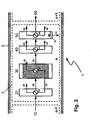
- a reaction cell 3 in a reactor 1 according to a first embodiment of the invention is shown schematically.
- the reaction cell n is located inside the reactor jacket 2, the inner wall of which forms the physical boundary of the reactor to the outside and bears the pressure selected for carrying out the exothermic equilibrium reaction.
- the preheating zone 20 in the reaction cell n is supplied with the gaseous, prereacted product stream from the upstream, upstream reaction cell n-1 supplied. If the reaction cell n is the first reaction cell in the direction of flow, the feed mixture is fed in via line 10.
- the gaseous product stream or the feed mixture is heated to the reaction temperature. This takes place in the indirect heat exchange with a heating fluid, which is fed to the heat exchanger 24 via line 22 and transfers its heat content there to the gaseous product stream or the feed mixture.
- the cooled heating fluid is discharged from the heat exchanger via line 26 and heated in a heating device (not shown) in order to feed it again to the heat exchanger 24.
- the heated feed mixture or the heated, gaseous product stream is fed via line 28 to the reaction zone 30, which contains a bed of a catalyst 31 active for the exothermic equilibrium reaction to be carried out and a cooling device 34 in a heat exchange relationship with the catalyst.
- the heat of reaction released by the exothermic reaction is removed by indirect heat exchange with a cooling fluid, which optionally partially evaporates, which is fed to the heat exchanger 34 via line 32 and, after absorption of the heat of reaction released in the catalyst bed, is removed via line 36.
- the heated cooling fluid is cooled again in a cooling device (not shown) in order to supply it to the heat exchanger 34 again.
- reaction zone Under the chosen reaction conditions in the catalyst bed, a partial conversion of the feed mixture or the gaseous product stream from the reaction cell n-1 into a gaseous product stream loaded with condensable reaction product takes place, which is discharged from the reaction zone via line 38 and fed to a first cooling zone 40 becomes.
- the gaseous product stream loaded with condensable reaction product is precooled, with the first portions of condensate being able to be obtained, which can be discharged from the reactor 1 via a separating device (not shown) and lines.
- the pre-cooling in the first cooling zone can also be carried out in such a way that the gas flow does not fall below the dew point.
- the pre-cooling takes place in the indirect heat exchange against a cooling fluid, which is fed to the heat exchanger 44 via line 42 and, after heat absorption, is removed via line 46.
- the heated cooling fluid is cooled again in a cooling device (not shown) in order to supply it to the heat exchanger 44 again.
- the precooled, but still loaded with at least part of the condensable reaction product, gaseous product stream is discharged from the first cooling zone via line 48 and fed to the second cooling zone 50.
- the gaseous product stream laden with condensable reaction product is further cooled, the dew point being undershot.
- the cooling takes place in the indirect heat exchange against a cooling fluid, which is supplied to the heat exchanger 54 via line 52 and, after absorbing heat, is removed via line 56.
- the heated cooling fluid is cooled again in a cooling device (not shown) in order to supply it to the heat exchanger 54 again.
- the gaseous product stream which has been cooled and freed from condensate, is discharged via line 60 from the second cooling zone 50 and thus also from the reaction cell n. It is then fed to the downstream reaction cell n + 1 in order to enable further conversion of the gaseous reactants into target products. If no further conversion of the gaseous reactants is desired or possible, the remaining residual gas is discharged from the reactor via line 60 and fed to further processing or disposal. Alternatively, the residual gas stream can be returned to the reactor after recycling and mixing with fresh feed mixture.
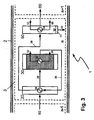
- FIGS. 2 to 7 Embodiments shown schematically correspond in principle to the same reference numerals as the device components as they have already been in explaining the first embodiment of the invention, Fig. 1 , have been described. The respective work steps and process conditions are also the same, unless otherwise described below.
- the cooling fluid heated by absorption of the heat of reaction in the reaction zone 30 is passed via line 36 to the heat exchanger 24 of the preheating zone 20 and used there as heating fluid for heating the feed mixture or the gaseous product stream from the upstream reaction cell.
- the heat integration within the reactor is improved.
- This option is particularly interesting if a (partially) evaporating cooling medium is used in the reaction zone 30 and at least partially condensed again in the preheating zone 20 and used there as a heating medium.
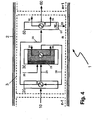
- the product stream discharged from the reaction zone 30 via line 38 is conducted as heating fluid to the heat exchanger 24 of the preheating zone 20 and is used there to heat the feed mixture or gaseous product stream from the upstream reaction cell brought in via line 10.
- the preheating zone 20 and the first cooling zone 40 thus coincide. In this way, too, the heat integration within the reactor is improved.
- the product stream cooled by heat exchange is then passed via line 26 to the second cooling zone 50.
- Fig. 4 contains the reaction zone in Fig. 4 two beds of catalysts 31, 33 with different activity for the exothermic equilibrium reaction, through which the feed mixture or gaseous product stream from the upstream reaction cell flows in succession.
- the catalyst bed 31 arranged downstream is cooled by means of the cooling device 34.
- the catalyst bed 33 contains a catalyst which, compared to the catalyst bed 31, has a higher activity. In this way, the catalytic conversion can initially be started and the amount of heat released thereby contributes to the heating of the reaction mixture to the selected inlet temperature in the catalyst bed 31, whereby the heat exchanger 24 in the preheating zone 20 can be reduced in size.
- a catalyst can be used in the catalyst bed 33 which has a lower activity compared to the catalyst bed 31. This is particularly advisable when the reaction potential of the gas mixture entering the reaction zone is high. This is in the in Fig. 4 The embodiment shown is the case since, via line 35, the reaction zone 30 in the reaction cell n is fed with fresh, ie not yet prereacted, feed mixture. As a result, the reaction is started more slowly and in a more controlled manner and the main part of the heat of reaction is released in the cooled catalyst bed 31.
- the supply of fresh, not yet prereacted feed mixture to reaction cells with n> 1 can also be useful in connection with the other embodiments of the reactor according to the invention discussed here. Furthermore, it can be advantageous to feed fresh, not yet prereacted feed mixture to more than one reaction cell with n> 1.
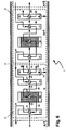
- the schematically illustrated embodiment shows an interconnection option for two successive reaction cells n and n + 1.
- Corresponding device components of the reaction cell n + 1 are marked with an apostrophe on the respective reference number.
- cooled heating fluid from the preheating zone 20 'of the reaction cell n + 1 is fed via line 26' to the heat exchanger 44 in the first cooling zone 40 of the reaction cell n, where it serves to precool the gas stream discharged from the reaction zone 30 via line 38.
- cooled heating fluid from the preheating zone 20 of the reaction cell n is fed via line 26 to the corresponding heat exchanger in the first cooling zone of the reaction cell n-1.
- the heating fluid heated in the heat exchanger 44 is fed to the heat exchanger 24 via line 46 and is used there to preheat the mixture entering the reaction cell n via line 10.
- the heated coolant discharged from the respective first cooling zone 40, 40 ', etc. is fed to the heat exchanger of the respective upstream reaction zone 30, 30', etc. as a coolant.
- the coolant, which is further heated in the reaction zone, is then fed to the heat exchanger of the respective upstream preheating zone as heating fluid.
- This configuration can be particularly suitable for carrying out exothermic reactions with a moderate exothermicity.
- a cooling fluid or heating fluid with a high heat absorption or heat output capacity is also favorable; fluids which, when used as a cooling fluid or heating fluid, have a phase transition from liquid to vapor or vice versa are particularly suitable for this.
- FIG Fig. 7 shown embodiment shown, in which a steam generator 70 is arranged outside the reactor. Hot condensate is removed from this and fed via line 32 to the heat exchanger 34 of the reaction zone 30 as a coolant, with it being partially evaporated. The resulting two-phase mixture, liquid and vapor, is returned to the steam generator via line 36.
- the hot condensate from the steam generator 70 can also be used as a coolant in the first cooling zone 40; this is shown schematically by the dashed line 47.
- Saturated steam is also withdrawn from the steam generator 70 and is fed to the heat exchanger 24 of the preheating zone 20 via line 22. At least partial condensation takes place as a result of the heat dissipation to the current brought in via line 10.
- the resulting stream can either be returned directly to the steam generator via line 26 or collected by means of other devices (not shown in the figure) and then at least partially returned to the steam generator in order to be evaporated again there.
- saturated steam can be discharged from the steam generator 70 via a line 78 and given off as export steam to external consumers.
- the preferred heat transfer medium or cooling medium are media that are close to their boiling point and therefore easily evaporate (cooling medium) or condense (heat transfer medium, heating medium). This ensures good heat dissipation due to the good heat transfer on the side of the evaporating or condensing medium and allows precise temperature control via the pressure.
- the pressure on the side of the heat transfer medium or cooling medium is regulated individually for each stage. As the catalyst running time increases, the conditions are adapted by setting the pressure on the cooling medium side accordingly, and the reaction temperature is thus adjusted in order to keep the conversion correspondingly high.
- steam can be used as a heat carrier in the methanol synthesis, for example.
- a wide temperature range e.g. 250 ° C: approx. 40 bar, 264 ° C: approx. 50 bar.
- an evaporating heat transfer oil e.g. Dowtherm A
- Cooling water or an evaporating heat transfer medium can be used in the cooling zones and / or condensation zones, while a condensing or even liquid heat transfer medium can be used in the heating zones.
- the heat transfer spaces are understood to mean the areas of the reactor in which there is an exchange of heat between the gas flow containing the reactants or reaction products and heating or cooling fluids, i.e. the preheating zone, the reaction zone and the cooling zones.
- a thermal sheet in the sense of the invention consists of two sheets, which are connected at the edges, preferably welded together and over the surface of which a large number of additional connections, preferably spot welds, which also connect the plates to one another, are distributed.
- Such plates can be produced automatically by robots or machines and thus at very reasonable prices.
- the sheets After welding, the sheets are expanded by hydraulic deformation, usually the injection of a liquid under high pressure, which creates cushion-like channels between the sheets through which a heating or cooling fluid can be passed. Through the heat transfer spaces, heat energy can therefore be supplied to as well as removed from certain areas of the reactor by passing heating or cooling fluids through.
- the reaction zones can be designed in such a way that two thermal sheets are initially arranged essentially in parallel in the reactor.
- Essentially parallel in the sense of the invention means that the alignment of the thermal sheets to one another from the parallel by a maximum of +/- 20 °, preferably a maximum of +/- 10 °, particularly preferably a maximum of +/- 5 °, very particularly preferably a maximum of +/- 2 "deviates from each other.
- the free space between the thermal sheets can then be filled with a bed of solid, granular, particulate or pellet-shaped catalyst, the lateral closure of the resulting catalyst bed by nets, grids, perforated sheets, grates, beds of inert material and / or the inner wall of the reactor is formed.
- At least one, preferably several, further, spaced apart thermal sheets are connected parallel to this arrangement, resulting in a package of plates and the free spaces between the thermal sheets being filled with catalyst beds.
- a compact, sandwich-like structure with an intensively acting cooling device extending over the length of the reaction zone is obtained in the reaction zone.
- the loading of the individual catalyst beds with the reaction gas mixture takes place in parallel.
- the plate packs can be aligned parallel or perpendicular to the longitudinal axis of the reactor, based on the free spaces filled with catalyst.
- the distances between the thermal plates are selected according to the heat of the reaction to be carried out: For strongly exothermic reactions, this distance is chosen to be smaller than for weaker exothermic reactions.Thereby, smaller plate distances are preferred in the first reaction zone, since this is where the greatest conversion is achieved and the greatest heat dissipation must be realized.
- the thermoplate spacing of the first reaction zone is preferably 20 to 45 mm.
- the distance refers to the distance from the center line to the center line, i.e. H. the clear distance between the plates is correspondingly smaller depending on the thermal sheet thickness and the expansion of the cavity.
- the distance is adapted to the dimensions of the catalyst particles in order to ensure optimal heat dissipation and good bulk material behavior when filling and emptying the catalyst without bridging. In the second and the subsequent reaction zones, the distances are usually chosen to be greater.
- adiabatic that is, uncooled reactor beds can be provided both downstream and upstream of the cooled plate packs. This can be of particular interest if only a residual conversion is to be achieved and cooling of the reaction is no longer necessary due to the low generation of heat or at the entry into a reaction stage if it is advantageous to achieve a rapid temperature increase before the reactants enter the cooled area of the reaction zone.
- thermal sheets can advantageously be used in the sense of a plate heat exchanger.
- tube end plates as required for tube bundle heat exchangers.
- logistical and manufacturing advantages are obtained, since the number of different components of the reactor and thus the complexity of the apparatus are reduced.
- a method according to the invention with a reactor with three reaction cells is compared with one with a three-stage technical reactor which comprises two water-cooled reactors WCR connected in parallel, followed downstream by a gas-cooled reactor GCR.
- the technical system has no intermediate condensation between WCR and GCR.
- the feed gas is the same in both cases in terms of composition and molar flow; it is a synthesis gas with the following composition: 8.4% by volume CO 2 , 20.1% by volume CO, 68% by volume H 2 , remainder Inert components.
- the inlet pressure into the reactor is in each case 75 bar, overpressure. Table 1 shows the essential comparative data for both reactors.
- X pp (k) denotes the conversion of component k per pass through the reactor (per pass) and X tot (k) denotes its total conversion via the reactor including the gas circuit.
- STY is the space-time yield of methanol in kg / h, based on one liter of catalyst volume.
- a process with a single-stage, water-cooled reactor for methanol synthesis is compared with a process according to the invention with a reactor which comprises four reaction cells, the process according to the invention being operated without recycling.
- the feed gas is the same in both cases in terms of composition and molar flow, it is a synthesis gas with the following composition: 7 vol .-% CO 2 , 16 vol .-% CO, 73 vol .-% H 2 , the rest of the inert components.
- the inlet pressure into the reactor is in each case 75 bar, overpressure.
- Table 2 Comparison of the characteristics of the process according to the invention with a reactor with four reaction cells without recirculation with a process with a single-stage water-cooled methanol synthesis reactor Methanol synthesis reactor (single-stage cooled reactor with high gas recirculation rate) Reactor with four reaction cells without gas recirculation Comparative example invention X pp (CO) /% 90.8 99.7 Xpp (CO 2 ) /% 62.8 93.9 Xpp (COx) /% 80.6 97.8 X dead (CO) /% 99.2 99.7 X dead (CO 2 ) /% 94.7 93.9 X dead (CO x ) /% 97.9 97.8 STY (MeOH) / kg / (h liter cat ) 0.98 1.15 Feedback ratio 3.5 0
- the invention proposes a reactor for carrying out exothermic equilibrium reactions, in particular for carrying out the methanol synthesis by heterogeneously catalyzed conversion of synthesis gas, which makes it possible to track the reaction conditions along the longitudinal coordinate of the reactor and thus to optimize what is to be done, for example, in the case of methanol synthesis leads to a reduction in the recycle ratio to smaller values, as are known when using the reactors known from the prior art.
- Corresponding return lines, cycle compressors, etc. can therefore be made smaller or, if necessary, they can be dispensed with entirely. This reduces the corresponding investment costs.
Description
Die Erfindung betrifft ein Verfahren zum Durchführen exothermer Gleichgewichtsreaktionen, insbesondere für die Durchführung der Methanolsynthese durch heterogen-katalysierte Umsetzung von Wasserstoff und Kohlenoxide umfassendem Synthesegas an festen Katalysatoren.The invention relates to a method for carrying out exothermic equilibrium reactions, in particular for carrying out the methanol synthesis by heterogeneously catalyzed conversion of synthesis gas comprising hydrogen and carbon oxides over solid catalysts.
Verfahren zur Durchführung exothermer Gleichgewichtsreaktionen sind der Fachwelt seit langem bekannt. Eine industriell besonders wichtige Reaktion dieses Typs ist die Methanolsynthese durch heterogen-katalytische Umsetzung von Synthesegas, also Gemischen
Ein moderneres, zweistufiges Verfahren zur Herstellung von Methanol ist beispielsweise aus der
In der wassergekühlten Reaktorstufe wird üblicherweise der Hauptumsatz des Synthesegases (CO, CO2, H2) erzielt und der größte Teil der Reaktionswärme abgeführt, während in der gasgekühlten Stufe bei milderen Bedingungen ein dennoch erheblicher Teil des Synthesegases umgesetzt wird.In the water-cooled reactor stage, the main conversion of the synthesis gas (CO, CO2, H2) is usually achieved and most of the heat of reaction is dissipated, while in the gas-cooled stage, under milder conditions, a considerable part of the synthesis gas is converted.
In manchen Anlagenkonfigurationen wird zusätzlich eine Zwischenkondensationsstufe zwischen den beiden Reaktionsstufen vorgesehen, um den Anteil der gebildeten Reaktionsprodukte (vorwiegend Methanol und Wasser) im Einsatzgas zur zweiten Reaktionsstufe zu verringern und damit den erzielbaren Umsatz der Edukte weiter zu erhöhen. Eine solche Anlagenkonfigurationen wird beispielsweise in der
Bei dem wassergekühlten Reaktor (WCR) handelt es sich üblicherweise um einen Röhrenreaktor mit entsprechenden Rohrplatten, bei dem der Katalysator in die Rohre gefüllt wird, während die Kühlung mittels siedendem Wasser bzw. Dampferzeugung auf der Mantelseite um die Rohre erfolgt. Im gasgekühlten Reaktor (GCR) erfolgt die Kühlung mit dem Einsatzgas, welches durch die Rohre geführt wird und sich auf dem Weg zur ersten Reaktionsstufe (WCR) erwärmt, während der Katalysator um die Rohre gefüllt wird und die Reaktion auf der Mantelseite des GCR stattfindet. Die Reaktionsstufen sind hinsichtlich ihrer Nennweite mit großen bzw. sehr großen Rohrleitungen verbunden; je nach Anlagenkapazität sind Rohrdurchmesser von bis zu 1 m möglich. Dies ist vor allem auf die großen Gasmengen zurückzuführen, die zu der zweiten Stufe zurückgeführt (Recycle-Gas) und dem Frischgas, also frischem Synthesegas aus der Gaserzeugung, zugemischt werden. Das sich ergebende Gasgemisch aus Rückführungsgas und Frischgas wird nach erfolgter Vorwärmung im GCR der ersten Reaktionsstufe (WCR) zugeführt. Die Rückführungsgasmenge (Recycle-Gas) ist üblicherweise deutlich größer als die Frischgasmenge und ist vom erzielten Umsatz in der Reaktorsektion abhängig. Das Rückführverhältnis RR (RR=R/F) aus Rückführungsgasmenge (R) zu Frischgasmenge (F) liegt oft über 2 und in einigen Fällen sogar über 3,5. Je niedriger der Umsatz von Synthesegas durch die Reaktorsektion per Durchgang ist, um so höher ist das erforderliche Rückführverhältnis RR, um eine hinreichende Ausbeute zu erzielen.The water-cooled reactor (WCR) is usually a tubular reactor with corresponding tube plates, in which the catalyst is filled into the tubes, while the tubes are cooled by means of boiling water or steam generation on the shell side. In the gas-cooled reactor (GCR), the cooling takes place with the feed gas, which is fed through the tubes and warms up on the way to the first reaction stage (WCR), while the catalyst is filled around the tubes and the reaction takes place on the shell side of the GCR. The reaction stages are large or very large in terms of their nominal diameter Pipelines connected; Depending on the system capacity, pipe diameters of up to 1 m are possible. This is mainly due to the large amounts of gas that are returned to the second stage (recycle gas) and mixed with the fresh gas, i.e. fresh synthesis gas from gas generation. The resulting gas mixture of recirculation gas and fresh gas is fed to the first reaction stage (WCR) after it has been preheated in the GCR. The amount of recycle gas (recycle gas) is usually significantly greater than the amount of fresh gas and depends on the conversion achieved in the reactor section. The recirculation ratio RR (RR = R / F) from the recirculation gas amount (R) to the fresh gas amount (F) is often over 2 and in some cases even over 3.5. The lower the conversion of synthesis gas through the reactor section per passage, the higher the recycle ratio RR required to achieve a sufficient yield.
Damit erhöht sich die umlaufende Gasmenge entsprechend, was die Belastung der Reaktoren erhöht und größere Rohrnennweiten der verbindenden Rohrleitungen bedarf und auch zu einem höherem Bedarf an Kompressionsenergie (höhere Durchflussmenge und Druckverlust) führt.This increases the amount of gas circulating accordingly, which increases the load on the reactors and requires larger pipe sizes of the connecting pipelines and also leads to a higher demand for compression energy (higher flow rate and pressure loss).
Das Patentdokument
Bei dem in Patentdokument
Das Patentdokument
Das Patentdokument
Das Patentdokument
Es kann festgestellt werden, dass trotz der Vielzahl der im Stand der Technik vorgeschlagenen technischen Lösungen weiterhin Bedarf an Verfahren zum Durchführen exothermer Gleichgewichtsreaktionen, insbesondere für die Durchführung der Methanolsynthese durch heterogen-katalysierte Umsetzung von Wasserstoff und Kohlenoxide umfassendem Synthesegas an festen Katalysatoren besteht, die eine verbesserte Kontrolle und Steuerung der Reaktion in den einzelnen Synthesestufen gestatten.It can be stated that, despite the large number of technical solutions proposed in the prior art, there is still a need for processes for carrying out exothermic equilibrium reactions, in particular for carrying out the methanol synthesis by heterogeneously catalyzed conversion of synthesis gas comprising hydrogen and carbon oxides to solid catalysts that have a allow improved control and regulation of the reaction in the individual synthesis stages.
Die Aufgabe der vorliegenden Erfindung besteht daher darin, ein Verfahren anzugeben, das die beschriebenen Nachteile der aus dem Stand der Technik bekannten Verfahren nicht aufweist und das insbesondere einen hohen Umsatz bezüglich der Zielprodukte der exothermen Reaktion sowie die Möglichkeit bietet, die Reaktionsbedingungen entlang der Längskoordinate des Reaktors nachzuführen und somit zu optimieren, was beispielsweise im Falle der Methanolsynthese zu einer Reduzierung des Rückführverhältnisses auf kleinere Werte führt, wie sie bei Verwendung der aus dem Stand der Technik bekannten Verfahren bekannt sind.The object of the present invention is therefore to provide a method which does not have the disadvantages described of the methods known from the prior art and which in particular offers a high conversion with respect to the target products of the exothermic reaction and the possibility of adjusting the reaction conditions along the longitudinal coordinate of the To track the reactor and thus optimize it, which in the case of methanol synthesis, for example, leads to a reduction in the recycle ratio to smaller values, as are known when using the processes known from the prior art.
Diese Aufgabe wird durch ein Verfahren mit den Merkmalen des Anspruchs 1 gelöst. Weitere Ausgestaltungen der Erfindung ergeben sich aus den Unteransprüchen.This object is achieved by a method with the features of
Verfahren zum Herstellen von Methanol durch Umsetzen eines Wasserstoff und Kohlenoxide enthaltenden Synthesegaseinsatzes, umfassend folgende Verfahrensschritte:
- (a) Bereitstellen eines Reaktors, umfassend mehrere Reaktionszellen in einem Reaktormantel, wobei jede Reaktionszelle die folgenden, hintereinander geschalteten und in Fluidverbindung miteinander stehenden Baugruppen umfasst:
- (aa) eine Vorwärmzone, geeignet zum Aufheizen des Einsatzgemischs oder des gasförmigen Produktstroms aus der vorgelagerten Reaktionszelle, wobei die Vorwärmzone in der ersten Reaktionszelle in Strömungsrichtung des gasförmigen Einsatzgemischs optional entfallen kann,
- (ab) mindestens eine Reaktionszone, enthaltend einen für die durchzuführende exotherme Gleichgewichtsreaktion aktiven Katalysator als Katalysatorschüttung in einem Katalysatorbett und eine mit dem Katalysatorbett in einer Wärmeaustauschbeziehung stehende Kühlvorrichtung,
- (ac) mindestens eine Kühlzone, enthaltend eine Kühlvorrichtung, geeignet zur Abkühlung des aus der Reaktionszone austretenden, teilumgesetzten und mit kondensierbarem Reaktionsprodukt beladenen, gasförmigen Produktstroms auf eine Temperatur unterhalb des Taupunktes dieses Gases,
- (ad) eine Abscheidezone, enthaltend eine Phasentrennvorrichtung zum Auftrennen des aus der Kühlzone austretenden Produktstroms in einen von Kondensat befreiten, gasförmigen Produktstrom und einen flüssiges Reaktionsprodukt umfassenden Kondensatstrom,
- (ae) Mittel zum Ausleiten des flüssiges Reaktionsprodukt umfassenden Kondensatstroms und optional Mittel zum Zuführen des Kondensatstroms zu einer Aufarbeitungsvorrichtung für das Reaktionsprodukt,
- (af) Mittel zum Ausleiten des von Kondensat befreiten, gasförmigen Produktstroms und Mittel zum Zuführen dieses gasförmigen Produktstroms zu einer nachgelagerten, stromabwärts angeordneten Reaktionszelle oder Mittel zum Ausleiten des gasförmigen Produktstroms aus dem Verfahren,
- (b) Bereitstellen eines Wasserstoff und Kohlenoxide enthaltenden Synthesegaseinsatzes und Einleiten desselben in den Reaktor,
- (c) Mindestens teilweises Umsetzen des Synthesegaseinsatzes in dem Reaktor unter Methanolumsetzungsbedingungen ,
- (d) Ausleiten eines Methanol und Wasser umfassenden, flüssigen Reaktorproduktstroms aus dem Reaktor und optional Zuführen des flüssigen Reaktorproduktstroms zu einer weiteren Abscheidevorrichtung und/oder mindestens einer weiteren Methanol-Aufarbeitungsvorrichtung,
- (g) Ausleiten eines Synthesegas-Abstroms und Rückführen dieses Synthesegas-Abstroms zu dem Reaktor mit einem festgelegten Rückführverhältnis und/oder Ausleiten des Synthesegas-Abstroms aus dem Verfahren.
- (a) Providing a reactor comprising a plurality of reaction cells in a reactor jacket, each reaction cell comprising the following components connected in series and in fluid communication with one another:
- (aa) a preheating zone suitable for heating up the feed mixture or the gaseous product stream from the upstream reaction cell, wherein the preheating zone in the first reaction cell in the direction of flow of the gaseous feed mixture can optionally be omitted,
- (ab) at least one reaction zone containing a catalyst active for the exothermic equilibrium reaction to be carried out as catalyst bed in a catalyst bed and a cooling device which is in a heat exchange relationship with the catalyst bed,
- (ac) at least one cooling zone containing a cooling device suitable for cooling the gaseous product stream exiting the reaction zone, partially converted and loaded with condensable reaction product, to a temperature below the dew point of this gas,
- (ad) a separation zone containing a phase separation device for separating the product stream emerging from the cooling zone into a gaseous product stream freed from condensate and a condensate stream comprising liquid reaction product,
- (ae) means for discharging the condensate stream comprising liquid reaction product and optionally means for feeding the condensate stream to a work-up device for the reaction product,
- (af) means for discharging the gaseous product stream freed from condensate and means for feeding this gaseous product stream to a downstream, downstream reaction cell or means for discharging the gaseous product stream from the process,
- (b) providing a synthesis gas feed containing hydrogen and carbon oxides and introducing it into the reactor,
- (c) At least partial conversion of the synthesis gas feed in the reactor under methanol conversion conditions,
- (d) discharging a liquid reactor product stream comprising methanol and water from the reactor and optionally feeding the liquid reactor product stream to a further separation device and / or at least one further methanol work-up device,
- (g) discharging a synthesis gas effluent and recycling this synthesis gas effluent to the reactor with a fixed recycle ratio and / or discharging the synthesis gas effluent from the process.
Unter Fluidverbindung zwischen zwei Bereichen des erfindungsgemäßen Reaktors wird dabei jegliche Art von Verbindung verstanden, die es ermöglicht, dass ein Fluid, beispielsweise der Einsatzgasstrom oder der Synthesegasproduktstrom, von dem einen zu dem anderen der beiden Bereiche strömen kann, unbeachtlich etwaiger zwischengeschalteter Bereiche oder Bauteile.A fluid connection between two areas of the reactor according to the invention is understood to mean any type of connection that enables a fluid, For example, the feed gas stream or the synthesis gas product stream, from which one of the two areas can flow to the other of the two areas, regardless of any interposed areas or components.
Mit Wärmeaustauschbeziehung ist die Möglichkeit des Wärmeaustauschs oder der Wärmeübertragung zwischen zwei Bereichen des erfindungsgemäßen Reaktors gemeint, wobei alle Mechanismen des Wärmeaustauschs oder der Wärmeübertragung wie Wärmeleitung, Wärmestrahlung oder konvektiver Wärmetransport zum Tragen kommen können. Unter einer indirekten Wärmeaustauschbeziehung wird dabei insbesondere die Art des Wärmeaustauschs oder der Wärmeübertragung verstanden, die durch eine Wand hindurch erfolgt (sog. Wärmedurchgang), der die Etappen des Wärmeübergangs von Fluid 1 auf die Oberfläche der Wand, der Wärmeleitung durch die Wand und des Wärmeübergangs von der Oberfläche der Wand auf Fluid 2 umfasst.The heat exchange relationship means the possibility of heat exchange or heat transfer between two regions of the reactor according to the invention, whereby all mechanisms of heat exchange or heat transfer such as heat conduction, heat radiation or convective heat transport can come into play. An indirect heat exchange relationship is understood to mean in particular the type of heat exchange or heat transfer that takes place through a wall (so-called heat transfer), which includes the stages of heat transfer from
Unter Methanolumsetzungsbedingungen sind die dem Fachmann an sich bekannten Verfahrensbedingungen, insbesondere von Temperatur, Druck und Verweilzeit, zu verstehen, wie sie oben beispielhaft genannt und detailliert im einschlägigen Schrifttum erörtert werden und bei denen mindestens ein Teilumsatz, bevorzugt allerdings technisch relevante Umsätze der Edukte CO bzw. CO2 und Wasserstoff zum Produkt Methanol erfolgt. Entsprechend wird unter einem für die Methanolsynthese aktiven Katalysator ein Katalysator verstanden, der unter Methanolumsetzungsbedingungen eben solche Umsätze bewirkt.Methanol conversion conditions are the process conditions known per se to the person skilled in the art, in particular of temperature, pressure and residence time, as mentioned above by way of example and discussed in detail in the relevant literature and in which at least a partial conversion, but preferably technically relevant conversions of the starting materials CO or CO 2 and hydrogen to the product methanol takes place. Correspondingly, a catalyst which is active for methanol synthesis is understood to mean a catalyst which under methanol conversion conditions brings about such conversions.
Unter Mitteln zum Einleiten, Ausleiten usw. werden alle die Vorrichtungen, Vorrichtungsbestandteile, Baugruppen und Bauteile verstanden, die es ermöglichen, dass das betreffende Fluid den betrachteten räumlichen Bereich, beispielsweise einen Behälter, verlässt. Hierunter werden insbesondere Rohrleitungen, Pumpen, Verdichter, sonstige Fördervorrichtungen sowie die entsprechenden Durchtrittsöffnungen in der Behälterwand verstanden.Means for introducing, discharging, etc. are understood to mean all the devices, device components, assemblies and components that enable the fluid in question to leave the spatial area under consideration, for example a container. This is understood to mean in particular pipelines, pumps, compressors, other conveying devices and the corresponding passage openings in the container wall.
Unter der katalytischen Aktivität, insbesondere im Zusammenhang mit einer unterschiedlichen katalytischen Aktivität beim Vergleich zweier unterschiedlicher Katalysatoren, wird der erzielte Umsatzgrad pro Längeneinheit des Katalysatorbetts von Edukten zu Produkten verstanden. Die Aktivität wird beeinflusst von der chemischen Zusammensetzung, Dotierung, Vergiftung, verfügbaren Oberfläche etc. des Katalysatormaterials, aber auch durch die Geometrie der Katalysatorpartikel und texturellen Parametern des Katalysatorbetts, z. B. dessen Porosität oder Packungsdichte. Aufgrund der Exothermie der betrachteten Reaktionen korreliert eine hohe katalytische Aktivität mit einer hohen Wärmefreisetzung pro Längeneinheit des Katalysatorbetts.Under the catalytic activity, in particular in connection with a different catalytic activity when comparing two different catalysts, the degree of conversion achieved per unit length of the catalyst bed from starting materials to products is understood. The activity is influenced by the chemical composition, doping, poisoning, available surface, etc. of the catalyst material, but also by the geometry of the catalyst particles and textural parameters of the catalyst bed, e.g. B. its porosity or packing density. Due to the exothermic nature of the reactions under consideration, a high catalytic activity correlates with a high release of heat per unit length of the catalyst bed.
Die in Anspruch 1. (aa) erwähnte Option, dass die Vorwärmzone in der ersten Reaktionszelle in Strömungsrichtung des gasförmigen Einsatzgemischs entfallen kann, wird insbesondere dann realisiert werden, wenn eine außerhalb des erfindungsgemäßen Reaktors angeordnete und diesem vorgeschaltete Heizvorrichtung vorhanden ist, die die Einstellung der Reaktionstemperatur vor Eintritt in die erste Reaktionszone gewährleistet.The option mentioned in
Der Erfindung liegt die Erkenntnis zugrunde, dass durch eine optimale Temperaturführung sowie wiederholtes Abführen von Produkten aus der Reaktionszone die Produktionsraten bzw. Raum-Zeit-Ausbeuten entlang des Reaktionsweges deutlich verbessert werden können, Das Temperaturprofil entlang des Reaktionsweges wird durch den Einsatz eines mehrstufigen Reaktionssystems erheblich verbessert, wodurch ein deutlich höherer Umsatz per Durchgang erzielt wird.The invention is based on the knowledge that through optimal temperature control and repeated removal of products from the reaction zone, the production rates or space-time yields along the reaction path can be significantly improved. The temperature profile along the reaction path becomes considerable through the use of a multi-stage reaction system improved, whereby a significantly higher turnover per pass is achieved.
Auch die Nebenproduktbildung bei der Methanolsynthese verringert sich bei der Durchführung des erfindungsgemäßen Verfahrens gegenüber dem Stand der Technik.The formation of by-products in methanol synthesis is also reduced when the process according to the invention is carried out compared with the prior art.
Ein verbessertes Temperaturprofil im Reaktor lässt sich grundsätzlich auch mit Hilfe eines Katalysator-Layer-Managements erzielen. Dabei würde man in dem Bereich, in dem man den höchsten Umsatz (Exothermie) und damit die höchsten Temperaturen erwartet, einen weniger aktiven Katalysator einsetzen und in Bereichen, wo weniger Umsatz erwartet wird, einen aktiveren Katalysator einsetzen. Jedoch ist ein solches Katalysator-Layer-Management relativ unflexibel, da man die verschiedenen Katalysatorlagen auf Basis einer bestimmten Katalysatoraktivität und einer entsprechenden Gaszusammensetzung auswählen und festlegen muss. Die Katalysatoraktivität verändert sich jedoch über seine Laufzeit der Syntheseanlage durch seine fortschreitende Desaktivierung.In principle, an improved temperature profile in the reactor can also be achieved with the aid of catalyst layer management. A less active catalyst would be used in the area in which the highest conversion (exothermic) and thus the highest temperatures are expected, and a more active catalyst would be used in areas where less conversion is expected. However, such a catalyst layer management is relatively inflexible, since the different catalyst layers are based on a certain catalyst activity and a corresponding Select and determine gas composition. However, the catalyst activity changes over the life of the synthesis plant due to its progressive deactivation.
Das Layer-Management und die zugehörige Kühlung des Reaktionsbettes müssen aufeinander abgestimmt werden. Während der Katalysatorlaufzeit und der damit verbundenen Katalysatordesaktivierung ändern sich die Bedingungen und eine Anpassung der Reaktionstemperatur und der zugehörigen Kühlung/Kühltemperatur ist wünschenswert, um die Desaktivierung zumindest teilweise zu kompensieren und einen hohen Umsatz bei geringer Nebenproduktbildung sicherzustellen. Mit den aus dem Stand der Technik bekannten Reaktoren lässt sich eine Anpassung der Kühlung nur für den gesamten Reaktor vornehmen; üblicherweise desaktivieren aber nicht alle Katalysatorschichten über die Betriebszeit in gleichem Maße. Die Einstellung spezifischer Reaktionsbedingungen stellt daher immer einen Kompromiss dar.The layer management and the associated cooling of the reaction bed must be coordinated with one another. During the catalyst running time and the associated catalyst deactivation, the conditions change and an adaptation of the reaction temperature and the associated cooling / cooling temperature is desirable in order to at least partially compensate for the deactivation and to ensure a high conversion with low by-product formation. With the reactors known from the prior art, the cooling can only be adapted for the entire reactor; Usually, however, not all catalyst layers deactivate to the same extent over the operating time. The setting of specific reaction conditions therefore always represents a compromise.
Mit dem erfindungsgemäßen Ansatz können die Reaktionsbedingungen in den verschiedenen Reaktionszellen dagegen individuell in Abhängigkeit der Katalysatoraktivität, der Gaszusammensetzung in jeder Stufe auch über die Laufzeit angepasst werden. Damit werden ein hoher Umsatz und eine geringe Nebenproduktbildung in den verschiedenen Reaktionszellen erreicht.With the approach according to the invention, however, the reaction conditions in the various reaction cells can be adapted individually depending on the catalyst activity, the gas composition in each stage and also over the running time. This achieves a high conversion and a low formation of by-products in the various reaction cells.
Mit der optimierten Temperaturführung werden auch die Maximaltemperaturen (sowie Temperaturspitzen, sog. Hot-Spots) im Katalysatorbett reduziert. Dies wirkt sich neben der Ausschleusung des Koppelproduktes aus dem Reaktionssystem, beispielsweise von Wasser bei der Methanolsynthese, positiv auf die Katalysatorlaufzeit aus. Es ist bekannt, dass sowohl hohe Temperaturen im Katalysatorbett als auch hohe Wasserkonzentrationen im Reaktionsgas zu einer rascheren Katalysatordesaktivierung beitragen.With the optimized temperature control, the maximum temperatures (and temperature peaks, so-called hot spots) in the catalyst bed are also reduced. In addition to discharging the by-product from the reaction system, for example water in the case of methanol synthesis, this has a positive effect on the catalyst running time. It is known that both high temperatures in the catalyst bed and high water concentrations in the reaction gas contribute to more rapid catalyst deactivation.
Mit dem vorgeschlagenen Konzept wird eine verbesserte Raum-Zeit-Ausbeute erzielt; somit kann auch die Rückführungsgasmenge (Gaskreislauf) erheblich reduziert werden. Grundsätzlich kann der Reaktor somit verkleinert werden und auch der Druckverlust reduziert sich. Durch die Reduzierung der Rückführungsgasmenge ergibt sich auch, dass die Menge und die Konzentration an akkumulierten Inertgasen, beispielsweise nicht umgesetztes Methan aus der Synthesegas-Erzeugung, im Synthesegas-kreislauf deutlich verringert werden und damit den gesamten Methanol-Synthesekreislauf mit Reaktorstufen, Kreislaufverdichter und weiteren Ausrüstungen entlastet. Als Optimum kann man den Vollumsatz pro Reaktordurchgang ansehen, bei dem auf einen Synthesegaskreislauf vollständig verzichtet werden könnte und mithin keine Ackumulierung von Inertgasen mehr auftritt. Ein derartiger Ansatz ist auch für andere Einsatzgaszusammensetzungen mit hohen Inertgasanteilen (z, B, hoher Stickstoffanteil bei Synthesegaserzeugung unter Verwendung von Luft) von besonderem Interesse, da im Synthesegaskreislauf die im Kreis zu führende Inertgasmenge ansteigt.With the proposed concept, an improved space-time yield is achieved; thus the amount of recirculated gas (gas cycle) can also be reduced considerably. In principle, the reactor can thus be made smaller and the pressure loss is also reduced. The reduction in the amount of recirculation gas results also that the amount and concentration of accumulated inert gases, for example unconverted methane from synthesis gas production, are significantly reduced in the synthesis gas cycle and thus relieve the entire methanol synthesis cycle with reactor stages, cycle compressors and other equipment. The optimum can be seen as the full conversion per reactor pass, at which a synthesis gas cycle could be completely dispensed with and consequently no accumulation of inert gases occurs. Such an approach is also of particular interest for other feed gas compositions with high proportions of inert gas (e.g. high proportion of nitrogen when generating synthesis gas using air), since the amount of inert gas to be circulated increases in the synthesis gas circuit.
Durch kontrolliertes Abscheiden der flüssigen Produkte sowie Temperaturkontrolle in den einzelnen Reaktionszellen wird ein Auskondensieren im Katalysatorbett vermieden und der Katalysator geschont.The controlled separation of the liquid products and temperature control in the individual reaction cells prevent condensation in the catalyst bed and protect the catalyst.
Die abgeschiedenen Kondensate mit unterschiedlichen Methanolanteilen können bei unterschiedlichen Bedingungen aufgereinigt bzw. direkt als Einsatz für nachgeschaltete Verfahren verwendet werden, was zu einer Energieeinsparung bei der Destillation führt.The separated condensates with different proportions of methanol can be purified under different conditions or used directly as input for downstream processes, which leads to energy savings in the distillation.
Um den apparativen Aufwand und die Investitionskosten gering zu halten, werden erfindungsgemäß mehrere Reaktionsstufen bzw. Reaktionszellen und auch mehrere Zwischenkondensationen sowie Kühl- und Aufheizstufen in einem Reaktor realisiert. Verbindende Rohrleitungen werden möglichst vermieden, so dass sich Investitionskosten für Rohrleitungen und der Druckverlust reduzieren und die Beanspruchung der Rohrleitungen durch thermisch-mechanische Spannungen abnimmt. Die Prozessmedien werden möglichst innerhalb des Apparates von Prozessstufe zu Prozessstufe geführt.In order to keep the outlay on equipment and the investment costs low, several reaction stages or reaction cells and also several intermediate condensations as well as cooling and heating stages are implemented in one reactor according to the invention. Connecting pipelines are avoided as far as possible, so that investment costs for pipelines and pressure loss are reduced and the stress on the pipelines due to thermal-mechanical stresses is reduced. If possible, the process media are routed from process stage to process stage within the apparatus.
Eine besondere Ausgestaltung des erfindungsgemäßen Verfahrens ist dadurch gekennzeichnet, dass das Rückführverhältnis Null ist. Durch die auf null reduzierte Kreisgasmenge reduziert sich neben der Reaktorgröße auch die Maße der Rohrleitungen erheblich. Ferner entfällt der bei den aus dem Stand der Technik bekannten Verfahren zur Methanolsynthese übliche Kreislaufverdichter und die erforderliche Kompressionsenergie verringert sich.A particular embodiment of the method according to the invention is characterized in that the return ratio is zero. The reduced amount of circulating gas reduces the size of the reactor as well as the dimensions of the pipelines considerable. Furthermore, the recycle compressor which is customary in the processes for methanol synthesis known from the prior art is omitted and the required compression energy is reduced.
Durch die erhebliche, idealerweise bis auf null zurückgehende Reduzierung der Rückführungsgasmenge ergibt sich auch, dass die Menge und die Konzentration an akkumulierten Inertgasen, wie beispielsweise nicht umgesetztes Methan aus der Synthesegas-Erzeugung, im Synthesegaskreislauf deutlich verringert werden und damit den gesamten Synthesegaskreislauf mit Reaktorstufen, Kreislaufverdichter und weiteren Ausrüstungen entlastet. Als Optimum kann man einen fast vollständigen Umsatz pro Reaktordurchgang ansehen, bei dem Gaskreislauf verzichtet werden könnte und keine Akkumulierung von Inertgasen mehr auftritt. Ein derartiger Ansatz wäre auch für Einsatzgasgemische mit hohen Inertgasanteilen (z. B. hoher Stickstoffanteil bei Synthesegaserzeugung unter Verwendung von Luft) von besonderem Interesse, da bei Vorhandensein eines Gaskreislaufs die im Kreis zu führende Inertgasmenge stark ansteigen würde, was die Wirtschaftlichkeit des Verfahrens belastet.The considerable reduction in the amount of recirculation gas, ideally going back to zero, also means that the amount and concentration of accumulated inert gases, such as unconverted methane from synthesis gas production, are significantly reduced in the synthesis gas cycle and thus the entire synthesis gas cycle with reactor stages, Circuit compressor and other equipment relieved. An almost complete conversion per passage through the reactor can be seen as the optimum, in which the gas cycle could be dispensed with and no accumulation of inert gases occurs. Such an approach would also be of particular interest for feed gas mixtures with high proportions of inert gas (e.g. high proportion of nitrogen in the case of synthesis gas generation using air), since the existence of a gas circuit would greatly increase the amount of inert gas to be circulated, which has a negative impact on the economics of the process.
Eine weitere vorteilhafte Ausgestaltung des erfindungsgemäßen Verfahrens sieht vor, dass die Katalysatormenge in den einzelnen Reaktionszonen (b) der einzelnen Reaktionszellen in Strömungsrichtung des Synthesegases durch den Reaktor abnimmt. Vergleichsversuche und Vergleichsrechnungen zeigen, dass unter diesen Bedingungen der Umsatz an Kohlenoxiden und die Raum-Zeit-Ausbeute in kg Methanol pro Liter Katalysatorvolumen und pro Stunde kgMoOH/(LiterKat h) höher sind als bei ansteigender bzw. gleichbleibender Katalysatormenge in den einzelnen Reaktionszonen der einzelnen Reaktionszellen in Strömungsrichtung des Synthesegases.A further advantageous embodiment of the process according to the invention provides that the amount of catalyst in the individual reaction zones (b) of the individual reaction cells decreases in the direction of flow of the synthesis gas through the reactor. Comparative experiments and comparative calculations show that under these conditions the conversion of carbon oxides and the space-time yield in kg of methanol per liter of catalyst volume and per hour of kg MoOH / (liter cat h) are higher than with an increasing or constant amount of catalyst in the individual reaction zones of the individual reaction cells in the direction of flow of the synthesis gas.
Weitere Aspekte des erfindungsgemäßen Verfahrens sind dadurch gekennzeichnet, dass die Temperatur des Kühlmediums in den Reaktionszonen (b) der einzelnen Reaktionszellen zwischen 180 und 300 °C, bevorzugt zwischen 190 und 270 °C, meist bevorzugt zwischen 200 und 260 °C liegt und in Strömungsrichtung des Synthesegases durch den Reaktor gleich bleibt oder abnimmt Vergleichsversuche und Vergleichsrechnungen zeigen, dass unter diesen Bedingungen der Umsatz an Kohlenoxiden und die Raum-Zeit-Ausbeute in kg Methanol pro Liter Katalysator und pro Stunde kgMeOH/(LiterKat h) höher sind als bei ansteigender Temperatur des Kühlmediums in den einzelnen Reaktionszonen der einzelnen Reaktionszellen in Strömungsrichtung des Synthesegases. Unter einem Gleichbleiben der Temperatur des Kühlmediums wird dabei eine Temperaturänderung von höchstens 5 K verstanden.Further aspects of the process according to the invention are characterized in that the temperature of the cooling medium in the reaction zones (b) of the individual reaction cells is between 180 and 300 ° C, preferably between 190 and 270 ° C, most preferably between 200 and 260 ° C, and in the direction of flow of the synthesis gas through the reactor remains the same or decreases. Comparative experiments and comparative calculations show that under these conditions the conversion of carbon oxides and the space-time yield in kg of methanol per liter of catalyst and per hour kg MeOH / (liter cat h) are higher than when the temperature of the cooling medium rises in the individual reaction zones of the individual reaction cells in the direction of flow of the synthesis gas. A temperature change of at most 5 K is understood to mean that the temperature of the cooling medium remains constant.
Besonders bevorzugt ist es in weiteren Aspekten der Erfindung, wenn bei dem erfindungsgemäßen Verfahren die Kondensationstemperatur in den Kühlzonen der einzelnen Reaktionszellen zwischen 20 und 120°C, bevorzugt zwischen 40 und 100 °C liegt und in Strömungsrichtung des Synthesegases durch den Reaktor gleich bleibt oder abnimmt. Vergleichsversuche und Vergleichsrechnungen zeigen, dass unter diesen Bedingungen der Umsatz an Kohlenoxiden und die Raum-Zeit-Ausbeute in kg Methanol pro Liter Katalysator und pro Stunde kgMeOH/(UterKat h) höher sind als bei ansteigender Kondensationstemperatur in Strömungsrichtung des Synthesegases.It is particularly preferred in further aspects of the invention if, in the process according to the invention, the condensation temperature in the cooling zones of the individual reaction cells is between 20 and 120 ° C., preferably between 40 and 100 ° C., and remains the same or decreases in the direction of flow of the synthesis gas through the reactor . Comparative experiments and comparative calculations show that under these conditions the conversion of carbon oxides and the space-time yield in kg of methanol per liter of catalyst and per hour of kg MeOH / (Uter Kat h) are higher than when the condensation temperature rises in the direction of flow of the synthesis gas.
In einem weiteren Aspekt des erfindungsgemäßen Verfahrens wird in allen Reaktionszellen der gleiche Wärmeträger verwendet und bei unterschiedlichen Druckstufen und zugehörigen Dampftemperaturen am jeweiligen Siedepunkt gearbeitet. Hierdurch ergeben sich logistische und technische Vorteile, da nur ein einziger Wärmeträger vorgehalten werden muss und Kreisläufe für die Zu- und Abfuhr weiterer Wärmeträger entfallen.In a further aspect of the process according to the invention, the same heat transfer medium is used in all reaction cells and work is carried out at different pressure levels and associated steam temperatures at the respective boiling point. This results in logistical and technical advantages, since only a single heat transfer medium has to be kept and there are no circuits for the supply and removal of further heat transfer medium.
In einem weiteren Aspekt des erfindungsgemäßen Verfahrens sind alle Reaktionszellen mit demselben Dampferzeuger verbunden und der Wärmeträger wird in flüssiger Form bereitgestellt wird und erfährt im Bereich der Reaktionszellen zumindest eine Teilverdampfung. Auch hier ergeben sich Vorteile, da nur ein einziger Dampferzeuger vorgesehen werden muss. Da mit der Verdampfung eine besonders große Enthalpieänderung verbunden ist, kann die in den Reaktionszellen freigesetzte Reaktionswärme auf diese Weise besonders effektiv abgeführt werden.In a further aspect of the method according to the invention, all reaction cells are connected to the same steam generator and the heat transfer medium is provided in liquid form and undergoes at least partial evaporation in the area of the reaction cells. Here, too, there are advantages since only a single steam generator has to be provided. Since the evaporation is associated with a particularly large change in enthalpy, the heat of reaction released in the reaction cells can be dissipated particularly effectively in this way.
Bevorzugt wird als Wärmeträger Wärmeträgeröl oder Wasser verwendet. Beide Wärmeträger sind gut handhabbar und leicht bzw. kostengünstig verfügbar.Thermal oil or water is preferably used as the heat transfer medium. Both heat carriers are easy to handle and easily and inexpensively available.
Weiterbildungen, Vorteile und Anwendungsmöglichkeiten der Erfindung ergeben sich auch aus der nachfolgenden Beschreibung von Ausführungsbeispielen und den Zeichnungen.Further developments, advantages and possible applications of the invention can also be found in the following description of exemplary embodiments and the drawings.
-
Fig. 1 eine Reaktionszelle in einem Reaktor gemäß einer ersten Ausführungsform der Erfindung,Fig. 1 a reaction cell in a reactor according to a first embodiment of the invention, -
Fig. 2 eine Reaktionszelle in einem Reaktor gemäß einer zweiten Ausführungsform der Erfindung,Fig. 2 a reaction cell in a reactor according to a second embodiment of the invention, -
Fig. 3 eine Reaktionszelle in einem Reaktor gemäß einer dritten Ausführungsform der Erfindung,Fig. 3 a reaction cell in a reactor according to a third embodiment of the invention, -
Fig. 4 eine Reaktionszelle in einem Reaktor gemäß einer vierten Ausführungsform der Erfindung,Fig. 4 a reaction cell in a reactor according to a fourth embodiment of the invention, -
Fig. 5 ein erstes Beispiel für die Verschaltung zweier aufeinanderfolgender Reaktionszellen in einem erfindungsgemäßen Reaktor,Fig. 5 a first example of the interconnection of two successive reaction cells in a reactor according to the invention, -
Fig. 6 ein zweites Beispiel für die Verschaltung zweier aufeinanderfolgender Reaktionszellen in einem erfindungsgemäßen Reaktor,Fig. 6 a second example of the interconnection of two successive reaction cells in a reactor according to the invention, -
Fig. 7 ein Ausführungsbeispiel für die Verschaltung eine Reaktionszelle in einem erfindungsgemäßen Reaktor mit einem Dampferzeuger.Fig. 7 an embodiment for the interconnection of a reaction cell in a reactor according to the invention with a steam generator.
In
Über Leitung 10 wird der Vorwärmzone 20 in der Reaktionszelle n der gasförmige, vorreagierte Produktstrom aus der vorgelagerten, stromaufwärts angeordneten Reaktionszelle n-1 zugeführt. Falls es sich bei der Reaktionszelle n um die erste Reaktionszelle in Strömungsrichtung handelt, wird über Leitung 10 das Einsatzgemisch zugeführt.Via
In der Vorwärmzone 20 wird der gasförmige Produktstrom oder das Einsatzgemisch auf die Reaktionstemperatur aufgeheizt. Dies erfolgt im indirekten Wärmetausch gegen ein Heizfluid, das über Leitung 22 dem Wärmetauscher 24 zugeführt wird und seinen Wärmeinhalt dort an den gasförmigen Produktstrom oder das Einsatzgemisch überträgt. Das abgekühlte Heizfluid wird über Leitung 26 aus dem Wärmetauscher abgeführt und in einer bildlich nicht dargestellten Heizvorrichtung aufgeheizt, um es erneut dem Wärmetauscher 24 zuzuführen.In the preheating
Das aufgeheizte Einsatzgemisch bzw. der aufgeheizte, gasförmige Produktstrom wird über Leitung 28 der Reaktionszone 30 zugeführt, die eine Schüttung eines für die durchzuführende exotherme Gleichgewichtsreaktion aktiven Katalysators 31 und eine mit dem Katalysator in einer Wärmeaustauschbeziehung stehende Kühlvorrichtung 34 enthält. Die Abfuhr der durch die exotherme Reaktion freigesetzten Reaktionswärme erfolgt im indirekten Wärmetausch gegen ein Kühlfluid, welches optional teilweise verdampft, das über Leitung 32 dem Wärmetauscher 34 zugeführt und nach Aufnahme der in der Katalysatorschüttung freigesetzte Reaktionswärme über Leitung 36 abgeführt wird. Das aufgeheizte Kühlfluid wird in einer bildlich nicht dargestellten Kühlvorrichtung erneut abgekühlt, um es erneut dem Wärmetauscher 34 zuzuführen.The heated feed mixture or the heated, gaseous product stream is fed via
In der Reaktionszone erfolgt unter den gewählten Reaktionsbedingungen in der Katalysatorschüttung eine Teilumsetzung des Einsatzgemischs bzw. des gasförmigen Produktstroms aus der Reaktionszelle n-1 in einen mit kondensierbarem Reaktionsprodukt beladenen, gasförmigen Produktstrom, der über Leitung 38 aus der Reaktionszone abgeführt und einer ersten Kühlzone 40 zugeführt wird.In the reaction zone, under the chosen reaction conditions in the catalyst bed, a partial conversion of the feed mixture or the gaseous product stream from the reaction cell n-1 into a gaseous product stream loaded with condensable reaction product takes place, which is discharged from the reaction zone via
In der ersten Kühlzone 40 erfolgt eine Vorkühlung des mit kondensierbarem Reaktionsprodukt beladenen, gasförmigen Produktstroms, wobei bereits erste Anteile an Kondensat erhalten werden können, die über eine bildlich nicht dargestellte Abscheidevorrichtung und Leitungen aus dem Reaktor 1 ausgeleitet werden können. Alternativ kann die Vorkühlung in der ersten Kühlzone aber auch so durchgeführt werden, dass der Taupunkt des Gasstroms noch nicht unterschritten wird. Die Vorkühlung erfolgt im indirekten Wärmetausch gegen ein Kühlfluid, das über Leitung 42 dem Wärmetauscher 44 zugeführt und nach Wärmeaufnahme über Leitung 46 abgeführt wird. Das aufgeheizte Kühlfluid wird in einer bildlich nicht dargestellten Kühlvorrichtung erneut abgekühlt, um es erneut dem Wärmetauscher 44 zuzuführen.In the
Der vorgekühlte, aber immer noch mindestens mit einem Teil des kondensierbaren Reaktionsprodukts beladene, gasförmigen Produktstrom wird über Leitung 48 aus der ersten Kühlzone ausgeleitet und der zweiten Kühlzone 50 zugeführt. In der zweiten Kühlzone 50 erfolgt die weitere Abkühlung des mit kondensierbarem Reaktionsprodukt beladenen, gasförmigen Produktstroms, wobei dessen Taupunkt unterschritten wird. Hierbei wird ein flüssiges Kondensat erhalten, das mittels einer in die zweite Kühlzone integrierten Abscheidevorrichtung 51 vom Gasstrom abgetrennt und mittels Leitung 53 aus dem Reaktor ausgeleitet und der bildlich nicht dargestellten Produktaufarbeitung zugeführt wird. Die Abkühlung erfolgt im indirekten Wärmetausch gegen ein Kühlfluid, das über Leitung 52 dem Wärmetauscher 54 zugeführt und nach Wärmeaufnahme über Leitung 56 abgeführt wird. Das aufgeheizte Kühlfluid wird in einer bildlich nicht dargestellten Kühlvorrichtung erneut abgekühlt, um es erneut dem Wärmetauscher 54 zuzuführen.The precooled, but still loaded with at least part of the condensable reaction product, gaseous product stream is discharged from the first cooling zone via
Der abgekühlte und von Kondensat befreite, gasförmige Produktstrom wird über Leitung 60 aus der zweiten Kühlzone 50 und somit auch aus der Reaktionszelle n ausgeleitet. Er wird dann der stromabwärts angeordneten Reaktionszelle n+1 zugeführt, um eine weitere Umsetzung der gasförmigen Reaktanten zu Zielprodukten zu ermöglichen. Wenn keine weitere Umsetzung der gasförmigen Reaktanten erwünscht oder möglich ist, wird das verbliebene Restgas über Leitung 60 aus dem Reaktor ausgeleitet und der weiteren Aufarbeitung bzw. Entsorgung zugeführt. Alternativ kann der Restgasstrom nach Rückführen und Vermischen mit frischem Einsatzgemisch erneut dem Reaktor aufgegeben werden.The gaseous product stream, which has been cooled and freed from condensate, is discharged via
In den in
Im Unterschied zu der ersten Ausgestaltung wird in
Im Unterschied zu der ersten Ausgestaltung wird in
Im Unterschied zu der zuvor erörterten Ausgestaltung gemäß
Alternativ kann in der Katalysatorschüttung 33 ein Katalysator eingesetzt werden, der im Vergleich zu der Katalysatorschüttung 31 eine geringere Aktivität aufweist. Dies empfiehlt sich besonders dann, wenn das Reaktionspotential des in die Reaktionszone eintretenden Gasgemischs hoch ist. Dies ist in der in
Das Zuführen frischen, noch nicht vorreagierten Einsatzgemischs zu Reaktionszellen mit n > 1 kann auch in Verbindung mit den anderen hier erörterten Ausgestaltungen des erfindungsgemäßen Reaktors sinnvoll sein. Ferner kann es vorteilhaft sein, frisches, noch nicht vorreagiertes Einsatzgemisch zu mehr als einer Reaktionszelle mit n > 1 zuzuführen.The supply of fresh, not yet prereacted feed mixture to reaction cells with n> 1 can also be useful in connection with the other embodiments of the reactor according to the invention discussed here. Furthermore, it can be advantageous to feed fresh, not yet prereacted feed mixture to more than one reaction cell with n> 1.
In der in
Im Unterschied zu der zuvor erörterten Ausgestaltung gemäß
Bei den beiden zuletzt erörterten Ausgestaltungen kann es zudem sinnvoll sein, die aufgeheizten Kühlfluide bzw. abgekühlten Heizfluide zunächst zu einer oder mehrerer außerhalb des Reaktors angeordneten Kühl. bzw. Heizvorrichtungen zuzuführen, um die volle Wärmeaufnahme- bzw. Wärmeabgabekapazität des jeweiligen Fluids wiederherzustellen. Die Anordnung dieser externen Kühl- bzw. Heizvorrichtungen könnte beispielsweise im Leitungsweg der Leitungen 26,26' usw. (Aufheizen), 46, 46' usw. (Kühlen) bzw. 36, 36' usw. (Kühlen) erfolgen.In the two configurations discussed last, it can also be useful to initially transfer the heated cooling fluids or cooled heating fluids to one or more coolers arranged outside the reactor. or heaters to supply restore the full heat absorption or heat output capacity of the respective fluid. These external cooling or heating devices could be arranged, for example, in the conduction path of the
Die Verschaltung mit einer externen Kühl- bzw. Heizvorrichtung ist schematisch in der in
Das Heißkondensat aus dem Dampferzeuger 70 kann ferner als Kühlmittel in der ersten Kühlzone 40 verwendet werden; dies ist schematisch durch die gestrichelte Leitung 47 dargestellt.The hot condensate from the
Dem Dampferzeuger 70 wird ferner Sattdampf entnommen, welcher über Leitung 22 dem Wärmetauscher 24 der Vorwärmzone 20 zugeführt wird. Durch die Wärmeabgabe an den über Leitung 10 herangeführten Strom erfolgt zumindest eine Teilkondensation. Der resultierende Strom kann entweder direkt über Leitung 26 zum Dampferzeuger zurückgeführt oder mittels anderer Vorrichtungen (bildlich nicht dargestellt) gesammelt werden und dann wieder zumindest teilweise zum Dampferzeuger zurückgeführt werden, um dort erneut verdampft zu werden.Saturated steam is also withdrawn from the
In dem Ausführungsbeispiel der
Als Wärmeträger bzw. Kühlmedium werden bevorzugt Medien eingesetzt, die sich in der Nähe ihres Siedepunktes befinden und daher leicht verdampfen (Kühlmedium) oder kondensieren (Wärmeträger, Heizmedium). Dies sichert eine gute Wärmeabfuhr durch den guten Wärmeübergang auf der Seite des verdampfenden bzw. kondensierenden Mediums und erlaubt eine präzise Temperaturregelung über den Druck. Um unterschiedliche Temperaturbedingungen in den verschiedenen Stufen einzustellen, wird der Druck auf der Seite des Wärmeträgers bzw. Kühlmediums individuell für jede Stufe geregelt. Mit zunehmender Katalysatorlaufzeit werden die Bedingungen mittels entsprechender Einstellung des Druckes auf der Kühlmediumseite angepasst und somit die Reaktionstemperatur nachgeführt, um den Umsatz entsprechend hoch zu halten.The preferred heat transfer medium or cooling medium are media that are close to their boiling point and therefore easily evaporate (cooling medium) or condense (heat transfer medium, heating medium). This ensures good heat dissipation due to the good heat transfer on the side of the evaporating or condensing medium and allows precise temperature control via the pressure. Around To set different temperature conditions in the various stages, the pressure on the side of the heat transfer medium or cooling medium is regulated individually for each stage. As the catalyst running time increases, the conditions are adapted by setting the pressure on the cooling medium side accordingly, and the reaction temperature is thus adjusted in order to keep the conversion correspondingly high.
Bezüglich der gewünschten Reaktionsbedingungen kann beispielsweise bei der Methanolsynthese Wasserdampf als Wärmeträger eingesetzt werden. Jedoch zeigt sich, dass bei Verwendung von Wasser für den gewünschten Temperaturbereich relativ große Druckunterschiede eingestellt werden müssen, um einen breiten Temperaturbereich abzudecken (z. B. 250°C: ca. 40 bar, 264 °C: ca. 50 bar). Benutzt man dagegen ein verdampfendes Wärmeträgeröl (z. B. Dowtherm A) in einem Kreislauf zur Wasserdampferzeugung, so kann man in einem sehr engen Druckbereich arbeiten und dennoch einen großen Temperaturbereich abdecken (Bsp.: 255 °C: 0,97 bar, 305 °C: 2,60 bar, entsprechend einem Temperaturbereich von 50 °C bei einem Druckunterschied von nur 1,6 bar. Dadurch kann man mit einer einfachen Wärmeträgeröl-Dampftrommel auf dem entsprechendem Anlagenniveau (ca. 20 bis 25 m) arbeiten und allein die Höhendifferenz nutzen, um die individuellen Druck- bzw. Temperaturbereiche einzustellen.With regard to the desired reaction conditions, steam can be used as a heat carrier in the methanol synthesis, for example. However, it turns out that when using water for the desired temperature range, relatively large pressure differences have to be set in order to cover a wide temperature range (e.g. 250 ° C: approx. 40 bar, 264 ° C: approx. 50 bar). If, on the other hand, an evaporating heat transfer oil (e.g. Dowtherm A) is used in a circuit to generate steam, one can work in a very narrow pressure range and still cover a large temperature range (e.g. 255 ° C: 0.97 bar, 305 ° C: 2.60 bar, corresponding to a temperature range of 50 ° C with a pressure difference of only 1.6 bar.This means that you can work with a simple heat transfer oil steam drum at the appropriate system level (approx. 20 to 25 m) and the difference in height alone to set the individual pressure or temperature ranges.
In den Abkühlzonen und/oder Kondensationszonen kann Kühlwasser oder auch ein verdampfender Wärmeträger eingesetzt werden, während in den Heizzonen ein kondensierender oder auch flüssiger Wärmeträger zum Einsatz kommen kann.Cooling water or an evaporating heat transfer medium can be used in the cooling zones and / or condensation zones, while a condensing or even liquid heat transfer medium can be used in the heating zones.
Bei vielen Ausgestaltungen, beispielsweise bei allen zuvor erörterten Ausgestaltungen, kann es vorteilhaft sein, die Wärmetransporträume durch jeweils wenigstens ein Thermoblech auszubilden. Unter den Wärmetransporträumen werden dabei die Bereiche des Reaktors verstanden, in denen es zum Wärmetausch zwischen der die Reaktanten bzw. Reaktionsprodukte enthaltenden Gasströmung und Heiz- bzw. Kühlfluiden kommt, also die Vorwärmzone, die Reaktionszone und die Kühlzonen.In many configurations, for example in all of the configurations discussed above, it can be advantageous to form the heat transfer spaces by at least one thermal sheet in each case. The heat transfer spaces are understood to mean the areas of the reactor in which there is an exchange of heat between the gas flow containing the reactants or reaction products and heating or cooling fluids, i.e. the preheating zone, the reaction zone and the cooling zones.
Ein Thermoblech im Sinne der Erfindung besteht aus zwei Blechen, welche an den Rändern verbunden, vorzugsweise zusammengeschweißt sind und über deren Oberfläche eine Vielzahl von zusätzlichen Verbindungen, vorzugsweise Punktschweißungen, die die Platten ebenfalls miteinander verbinden, verteilt sind. Solche Platten können automatisiert von Robotern oder Maschinen und somit zu sehr günstigen Preisen hergestellt werden. Nach der Verschweißung werden die Bleche durch eine hydraulische Umformung, in der Regel das Einpressen einer Flüssigkeit unter hohem Druck, expandiert, wodurch kissenartige Kanäle zwischen den Blechen entstehen, durch die ein Heiz- oder Kühlfluid geleitet werden kann. Über die Wärmetransporträume kann daher bestimmten Bereichen des Reaktor durch das Durchleiten von Heiz- bzw. Kühlfluiden sowohl Wärmeenergie zu- als auch abgeführt werden.A thermal sheet in the sense of the invention consists of two sheets, which are connected at the edges, preferably welded together and over the surface of which a large number of additional connections, preferably spot welds, which also connect the plates to one another, are distributed. Such plates can be produced automatically by robots or machines and thus at very reasonable prices. After welding, the sheets are expanded by hydraulic deformation, usually the injection of a liquid under high pressure, which creates cushion-like channels between the sheets through which a heating or cooling fluid can be passed. Through the heat transfer spaces, heat energy can therefore be supplied to as well as removed from certain areas of the reactor by passing heating or cooling fluids through.
Die Reaktionszonen können bei Verwendung von Thermoblechen so ausgestaltet werden, dass in dem Reaktor zunächst zwei Thermobleche im Wesentlichen parallel angeordnet werden. Im Wesentlichen parallel im Sinne der Erfindung bedeutet, dass die Ausrichtung der Thermobleche zueinander von der Parallelen maximal um +/- 20°, bevorzugt maximal um +/- 10°, besonders bevorzugt maximal um +/- 5°, ganz besonders bevorzugt maximal um +/- 2" voneinander abweicht. Danach kann der Freiraum zwischen den Thermoblechen mit einer Schüttung eines festen, körnigen, partikelförmigen oder pelletförmigen Katalysators aufgefüllt werden, wobei der seitliche Abschluss des sich ergebenden Katalysatorbettes durch Netze, Gitter, Lochbleche, Roste, Schüttungen von Inertmaterial und/oder die Reaktorinnenwand gebildet wird.When using thermal sheets, the reaction zones can be designed in such a way that two thermal sheets are initially arranged essentially in parallel in the reactor. Essentially parallel in the sense of the invention means that the alignment of the thermal sheets to one another from the parallel by a maximum of +/- 20 °, preferably a maximum of +/- 10 °, particularly preferably a maximum of +/- 5 °, very particularly preferably a maximum of +/- 2 "deviates from each other. The free space between the thermal sheets can then be filled with a bed of solid, granular, particulate or pellet-shaped catalyst, the lateral closure of the resulting catalyst bed by nets, grids, perforated sheets, grates, beds of inert material and / or the inner wall of the reactor is formed.
Besonders bevorzugt schließen sich parallel zu dieser Anordnung mindestens ein, bevorzugt mehrere weitere, beabstandete Thermobleche an, wobei sich insgesamt ein Plattenpaket ergibt und die Freiräume zwischen den Thermoblechen mit Katalysatorschüttungen aufgefüllt werden. Auf diese Weise wird in der Reaktionszone eine kompakte, sandwichartige Struktur mit einer intensiv wirkendenden, sich über die Länge der Reaktionszone erstreckenden Kühlvorrichtung erhalten. Die Beaufschlagung der einzelnen Katalysatorschüttungen mit dem Reaktionsgasgemisch erfolgt dabei parallel. Die Plattenpakete können, bezogen auf die mit Katalysator gefüllten Freiräume, parallel oder senkrecht zur Längsachse des Reaktors ausgerichtet werden.Particularly preferably, at least one, preferably several, further, spaced apart thermal sheets are connected parallel to this arrangement, resulting in a package of plates and the free spaces between the thermal sheets being filled with catalyst beds. In this way, a compact, sandwich-like structure with an intensively acting cooling device extending over the length of the reaction zone is obtained in the reaction zone. The loading of the individual catalyst beds with the reaction gas mixture takes place in parallel. The plate packs can be aligned parallel or perpendicular to the longitudinal axis of the reactor, based on the free spaces filled with catalyst.
Die Abstände zwischen den Thermoplatten werden gemäß der Wärmetönung der durchzuführenden Reaktion ausgewählt: Für stark exotherme Reaktionen wird dieser Abstand kleiner gewählt als für schwächer exotherme Reaktionen, Dabei werden in der ersten Reaktionszone kleinere Plattenabstände bevorzugt, da hier der größte Umsatz erzielt wird und die größte Wärmeabfuhr realisiert werden muss. Die Thermoblechplattenabstände der ersten Reaktionszone betragen im Falle der Methanolsynthese bevorzugt 20 bis 45 mm. Der Abstand bezieht sich dabei auf den Abstand von Mittellinie zur Mittellinie, d. h. der lichte Abstand zwischen den Platten fällt je nach Thermoblechdicke und Expansion des Hohlraumes entsprechend kleiner aus. Ferner wird der Abstand an die Abmessungen der Katalysatorpartikel angepasst, um eine optimale Wärmeabfuhr sowie ein gutes Schüttgutverhalten beim Befüllen und Entleeren des Katalysators ohne Brückenbildung sicherzustellen. In der zweiten und den nachfolgenden Reaktionszonen werden die Abstände üblicherweise größer gewählt.The distances between the thermal plates are selected according to the heat of the reaction to be carried out: For strongly exothermic reactions, this distance is chosen to be smaller than for weaker exothermic reactions.Thereby, smaller plate distances are preferred in the first reaction zone, since this is where the greatest conversion is achieved and the greatest heat dissipation must be realized. In the case of methanol synthesis, the thermoplate spacing of the first reaction zone is preferably 20 to 45 mm. The distance refers to the distance from the center line to the center line, i.e. H. the clear distance between the plates is correspondingly smaller depending on the thermal sheet thickness and the expansion of the cavity. Furthermore, the distance is adapted to the dimensions of the catalyst particles in order to ensure optimal heat dissipation and good bulk material behavior when filling and emptying the catalyst without bridging. In the second and the subsequent reaction zones, the distances are usually chosen to be greater.
Insbesondere bei horizontaler Anordnung des Reaktors bei gleichzeitig senkrechter Anordnung der Katalysatorschüttungen in den Reaktionszonen ergibt sich die Möglichkeit der einfachen Entfernung des Katalysators aus dem Reaktor zum Zwecke des Katalysatoraustauschs. Dabei sind zur Entleerung entsprechende Revisionsöffnungen im Reaktormantel vorzusehen, die beispielsweise durch einen Klapp- oder Schiebemechanismus betätigt werden. Der Schiebemechanismus kann sehr platzsparend ausgeführt werden, dabei ist es vorteilhaft, wenn sich die Tragroste der benachbarten Reaktionszonen mittels entsprechender Führungsschienen übereinander schieben lassen, so dass benachbarte Bereiche nacheinander entleert werden können.In particular when the reactor is arranged horizontally with the catalyst beds arranged vertically in the reaction zones, there is the possibility of simple removal of the catalyst from the reactor for the purpose of catalyst exchange. Appropriate inspection openings are to be provided in the reactor jacket for emptying, which are operated, for example, by a folding or sliding mechanism. The sliding mechanism can be designed to be very space-saving; it is advantageous if the supporting grids of the adjacent reaction zones can be pushed over one another by means of corresponding guide rails, so that adjacent areas can be emptied one after the other.
In besonderer Ausgestaltung lassen sich sowohl stromabwärts als auch stromaufwärts der gekühlten Plattenpakete adiabate, also ungekühlte Reaktorbetten vorsehen. Das kann vor allem interessant werden, wenn nur noch ein Restumsatz erzielt werden soll und eine Kühlung der Reaktion aufgrund der geringen Wärmeentwicklung nicht mehr notwendig ist oder am Eintritt in eine Reaktionsstufe, wenn es vorteilhaft ist, eine schnelle Temperaturerhöhung zu erzielen, bevor die Reaktanten den gekühlten Bereich der Reaktionszone eintreten.In a special embodiment, adiabatic, that is, uncooled reactor beds can be provided both downstream and upstream of the cooled plate packs. This can be of particular interest if only a residual conversion is to be achieved and cooling of the reaction is no longer necessary due to the low generation of heat or at the entry into a reaction stage if it is advantageous to achieve a rapid temperature increase before the reactants enter the cooled area of the reaction zone.
Auch bei der Ausgestaltung der Vorwärmzone und der Kühlzonen können Thermobleche vorteilhaft im Sinne eines Plattenwärmetauschers eingesetzt werden. Auf die Verwendung von Rohrendplatten, wie sie bei Rohrbündelwärmetauschem erforderlich sind, kann dabei verzichtet werden. Zudem werden logistische und fertigungstechnische Vorteile erhalten, da sich die Zahl unterschiedlicher Bauteile des Reaktors und damit die Komplexität des Apparates reduzieren.In the design of the preheating zone and the cooling zones, too, thermal sheets can advantageously be used in the sense of a plate heat exchanger. There is no need to use tube end plates, as required for tube bundle heat exchangers. In addition, logistical and manufacturing advantages are obtained, since the number of different components of the reactor and thus the complexity of the apparatus are reduced.
Eine weitere Ausgestaltungsmöglichkeit wird durch die Ausgestaltung der Wärmetransporträume mittels Lamellenwärmetauschern (plate fin heat exchanger) alternativ oder zusätzlich zu der Verwendung von Thermoblechen ermöglicht.Another design option is made possible by designing the heat transfer spaces by means of plate fin heat exchangers as an alternative or in addition to the use of thermal sheets.
In den nachfolgenden Tabellen werden Kenndaten zum Betrieb des Reaktors in dem erfindungsgemäßen Verfahren mit aus dem Stand der Technik bekannten Reaktoren für die heterogen-katalytische Synthese von Methanol aus Synthesegas verglichen.In the tables below, characteristic data for operating the reactor in the process according to the invention are compared with reactors known from the prior art for the heterogeneous catalytic synthesis of methanol from synthesis gas.
Im ersten Vergleichsfall wird ein erfindungsgemäßes Verfahren mit einem Reaktor mit drei Reaktionszellen einem solchen mit dreistufigem technischen Reaktor gegenübergestellt, der zwei parallel geschaltete wassergekühlte Reaktoren WCR, stromabwärts gefolgt von einem gasgekühlten Reaktor GCR, umfasst. Die technische Anlage verfügt über keine Zwischenkondensation zwischen WCR und GCR. Das Einsatzgas ist in beiden Fällen hinsichtlich Zusammensetzung und Stoffmengenstrom gleich, es handelt sich um ein Synthesegas mit folgender Zusammensetzung: 8,4 Vol.-% CO2, 20,1 Vol.-% CO, 68 Vol.-% H2, Rest Inertkomponenten. Der Eintrittsdruck in den Reaktor beträgt jeweils 75 bar, Überdruck. In Tabelle 1 sind die wesentlichen Vergleichsdaten für beide Reaktoren zusammengestellt. Dabei bedeutet Xpp(k) den Umsatz der Komponente k pro Durchgang durch den Reaktor (per pass) und Xtot(k) ihren Gesamtumsatz über den Reaktor inklusive Gaskreislauf. STY ist die Raum-Zeit-Ausbeute an Methanol in kg/h, bezogen auf einen Liter Katalysatorvolumen.In the first comparative case, a method according to the invention with a reactor with three reaction cells is compared with one with a three-stage technical reactor which comprises two water-cooled reactors WCR connected in parallel, followed downstream by a gas-cooled reactor GCR. The technical system has no intermediate condensation between WCR and GCR. The feed gas is the same in both cases in terms of composition and molar flow; it is a synthesis gas with the following composition: 8.4% by volume CO 2 , 20.1% by volume CO, 68% by volume H 2 , remainder Inert components. The inlet pressure into the reactor is in each case 75 bar, overpressure. Table 1 shows the essential comparative data for both reactors. X pp (k) denotes the conversion of component k per pass through the reactor (per pass) and X tot (k) denotes its total conversion via the reactor including the gas circuit. STY is the space-time yield of methanol in kg / h, based on one liter of catalyst volume.
Wie anhand der in Tabelle 1 zusammengestellten Daten zu erkennen ist, ist der Umsatz an Kohlenoxiden für den Gesamtreaktor in beiden Fällen vergleichbar; jedoch sind die Umsätze pro Reaktordurchgang für den erfindungsgemäßen Reaktor deutlich höher. Für letzteren sind zudem die Maximaltemperatur im Katalysatorbett, die Konzentration an Nebenprodukten und das benötigte Rückführverhältnis geringer.
In Tabelle 2 wird nachfolgend ein Verfahren mit einstufigem, wassergekühlten Reaktor zur Methanolsynthese mit einem erfindungsgemäßen Verfahren mit einem Reaktor verglichen, der vier Reaktionszellen umfasst, wobei das erfindungsgemäße Verfahren ohne Rückführung betrieben wird. Das Einsatzgas ist in beiden Fällen hinsichtlich Zusammensetzung und Stoffmengenstrom gleich, es handelt sich um ein Synthesegas mit folgender Zusammensetzung: 7 Vol.-% CO2, 16 Vol.-% CO, 73 Vol.-% H2, Rest Inertkomponenten. Der Eintrittsdruck in den Reaktor beträgt jeweils 75 bar, Überdruck. Tabelle 2: Vergleich der Kenndaten des erfindungsgemäßen Verfahrens mit Reaktor mit vier Reaktionszellen ohne Rückführung mit einem Verfahren mit einstufigem wassergekühlten Methanolsynthesereaktor
Mit dem erfindungsgemäßen Verfahren mit Reaktor mit vier Reaktionszellen wird ohne Rückführung eine um rund 15 % höhere Raum-Zeit-Ausbeute an Methanol erhalten. Insbesondere der CO2-Umsatz pro Reaktordurchgang ist deutlich höher als bei dem Vergleichsbeispiel.With the process according to the invention with a reactor with four reaction cells, a space-time yield of methanol that is around 15% higher is obtained without recycling. In particular, the CO 2 conversion per reactor passage is significantly higher than in the comparative example.
In den nachfolgenden Tabellen wird der Einfluss bestimmter Verfahrensparameter in den einzelnen Reaktionszellen bei der heterogen-katalytischen Synthese von Methanol aus Synthesegas aufgezeigt. Die sonstigen Verfahrensbedingungen entsprechen denen des in Tabelle 2 dargestellten Beispiels (sog. Referenz in Tabellen 3 bis 5).
Mit der Erfindung wird ein Reaktor zum Durchführen exothermer Gleichgewichtsreaktionen, insbesondere für die Durchführung der Methanolsynthese durch heterogen-katalysierte Umsetzung von Synthesegas vorgeschlagen, der es ermöglicht, die Reaktionsbedingungen entlang der Längskoordinate des Reaktors nachzuführen und somit zu optimieren, was beispielsweise im Falle der Methanolsynthese zu einer Reduzierung des Rückführverhältnis auf kleinere Werte führt, wie sie bei Verwendung der aus dem Stand der Technik bekannten Reaktoren bekannt sind. Entsprechende Rückführleitungen, Kreislaufverdichter usw. können daher kleiner ausgestaltet werden oder es kann gegebenenfalls ganz auf sie verzichtet werden. Hierdurch reduzieren sich die entsprechenden Investitionskosten.The invention proposes a reactor for carrying out exothermic equilibrium reactions, in particular for carrying out the methanol synthesis by heterogeneously catalyzed conversion of synthesis gas, which makes it possible to track the reaction conditions along the longitudinal coordinate of the reactor and thus to optimize what is to be done, for example, in the case of methanol synthesis leads to a reduction in the recycle ratio to smaller values, as are known when using the reactors known from the prior art. Corresponding return lines, cycle compressors, etc. can therefore be made smaller or, if necessary, they can be dispensed with entirely. This reduces the corresponding investment costs.
Durch die Optimierung der Reaktionsbedingungen entlang der Längskoordinate des Reaktors wird ferner die Bildung unerwünschter Nebenprodukte reduziert, wodurch ein reineres Zielprodukt erhalten wird und sich der Reinigungsaufwand verringert.By optimizing the reaction conditions along the longitudinal coordinate of the reactor, the formation of undesired by-products is also reduced, as a result of which a purer target product is obtained and the cleaning effort is reduced.
- [1][1]
- Reaktorreactor
- [2][2]
- ReaktormantelReactor jacket
- [3][3]
- ReaktionszelleReaction cell
- [10][10]
- Leitungmanagement
- [20][20]
- VorwärmzonePreheating zone
- [22][22]
- Leitungmanagement
- [24][24]
- WärmetauscherHeat exchanger
- [26][26]
- Leitungmanagement
- [28][28]
- Leitungmanagement
- [30][30]
- ReaktionszoneReaction zone
- [31][31]
- KatalysatorbettCatalyst bed
- [32][32]
- Leitungmanagement
- [33][33]
- KatalysatorbettCatalyst bed
- [34][34]
- WärmetauscherHeat exchanger
- [35][35]
- Leitungmanagement
- [36][36]
- Leitungmanagement
- [38][38]
- Leitungmanagement
- [40][40]
- erste Kühlzonefirst cooling zone
- [42][42]
- Leitungmanagement
- [44][44]
- WärmetauscherHeat exchanger
- [46][46]
- Leitungmanagement
- [47][47]
- Leitungmanagement
- [48][48]
- Leitungmanagement
- [50][50]
- zweite Kühl- und Abscheidezonesecond cooling and separation zone
- [51][51]
- AbscheidevorrichtungSeparation device
- [52][52]
- Leitungmanagement
- [53][53]
- Leitungmanagement
- [54][54]
- WärmetauscherHeat exchanger
- [56][56]
- Leitungmanagement
- [60][60]
- Leitungmanagement
- [70][70]
- DampferzeugerSteam generator
- [78][78]
- Leitungmanagement
Claims (11)
- Process for preparing methanol by converting a synthesis gas feed comprising hydrogen and carbon oxides, comprising the following process steps:(a) providing a reactor comprising multiple reaction cells in a reactor shell, wherein each reaction cell comprises the following series-connected assemblies that are in fluid connection with one another:(aa) a preheating zone suitable for heating the feed mixture or the gaseous product stream from the upstream reaction cell, wherein the preheating zone can optionally be dispensed with in the first reaction cell in flow direction of the gaseous feed mixture,(ab) at least one reaction zone comprising a catalyst active in respect of the exothermic equilibrium reaction to be conducted in the form of a catalyst packing in a catalyst bed, and a cooling apparatus in a heat-exchanging relationship with the catalyst bed,(ac) at least one cooling zone comprising a cooling apparatus suitable for cooling the partly converted gaseous product stream that has been laden with condensable reaction product and exits from the reaction zone to a temperature below the dew point of this gas,(ad) a deposition zone comprising a phase separation apparatus for separation of the product stream that exits from the cooling zone into a gaseous product stream that has been freed of condensate and a condensate stream comprising liquid reaction product,(ae) means of discharging the condensate stream comprising liquid reaction product and optionally means of feeding the condensate stream to a workup apparatus for the reaction product,(af) means of discharging the gaseous product stream that has been freed of condensate and means of feeding this gaseous product stream to a subsequent reaction cell arranged downstream or means of discharging the gaseous product stream from the process,(b) providing a synthesis gas feed comprising hydrogen and carbon oxides and introducing it into the reactor,(c) at least partly converting the synthesis gas feed in the reactor under methanol conversion conditions,(d) discharging a liquid reactor product stream comprising methanol and water from the reactor and optionally feeding the liquid reactor product stream to a further deposition apparatus and/or at least one further methanol workup apparatus,(g) discharging a synthesis gas output stream and recycling this synthesis gas output stream to the reactor with a fixed recycle ratio and/or discharging the synthesis gas output stream from the process.
- Process according to Claim 1, characterized in that the recycle ratio is zero.
- Process according to Claim 1 or 2, characterized in that the amount of catalyst in the individual reaction zones (ab) of the individual reaction cells decreases in flow direction of the synthesis gas through the reactor.
- Process according to any of the preceding claims, characterized in that the temperature of the cooling medium in the reaction zones (b) of the individual reaction cells is between 180 and 300°C, and remains the same or decreases in flow direction of the synthesis gas through the reactor.
- Process according to any of the preceding claims, characterized in that the temperature of the cooling medium in the reaction zones (b) of the individual reaction cells is between 190 and 270°C, and remains the same or decreases in flow direction of the synthesis gas through the reactor.
- Process according to any of the preceding claims, characterized in that the temperature of the cooling medium in the reaction zones (b) of the individual reaction cells is between 200 and 260°C, and remains the same or decreases in flow direction of the synthesis gas through the reactor.
- Process according to any of the preceding claims, characterized in that the condensation temperature in the cooling zones of the individual reaction cells is between 20 and 120°C, and remains the same or decreases in flow direction of the synthesis gas through the reactor.
- Process according to any of the preceding claims, characterized in that the condensation temperature in the cooling zones of the individual reaction cells is between 40 and 100°C, and remains the same or decreases in flow direction of the synthesis gas through the reactor.
- Process according to any of the preceding claims, characterized in that the same heat carrier is used in all reaction cells and the temperature employed is the respective boiling point at different pressure levels and corresponding vapour temperatures.
- Process according to any of the preceding claims, characterized in that all reaction cells are connected to the same steam generator and the heat carrier is provided in liquid form and undergoes at least partial evaporation in the region of the reaction cells.
- Process according to any of the preceding claims, characterized in that the heat carrier is heat carrier oil or water.
Priority Applications (5)
| Application Number | Priority Date | Filing Date | Title |
|---|---|---|---|
| EP17400025.7A EP3401300B1 (en) | 2017-05-12 | 2017-05-12 | Method for the production of methanol |
| US16/612,537 US10913698B2 (en) | 2017-05-12 | 2018-04-26 | Process for conducting exothermic equilibrium reactions |
| PCT/EP2018/025131 WO2018206155A1 (en) | 2017-05-12 | 2018-04-26 | Process for conducting exothermic equilibrium reactions |
| RU2019138352A RU2787160C2 (en) | 2017-05-12 | 2018-04-26 | Method for conducting exothermic equilibrium reactions |
| CN201880030215.4A CN110603241B (en) | 2017-05-12 | 2018-04-26 | Method for carrying out exothermic equilibrium reactions |
Applications Claiming Priority (1)
| Application Number | Priority Date | Filing Date | Title |
|---|---|---|---|
| EP17400025.7A EP3401300B1 (en) | 2017-05-12 | 2017-05-12 | Method for the production of methanol |
Publications (2)
| Publication Number | Publication Date |
|---|---|
| EP3401300A1 EP3401300A1 (en) | 2018-11-14 |
| EP3401300B1 true EP3401300B1 (en) | 2021-06-23 |
Family
ID=59070584
Family Applications (1)
| Application Number | Title | Priority Date | Filing Date |
|---|---|---|---|
| EP17400025.7A Active EP3401300B1 (en) | 2017-05-12 | 2017-05-12 | Method for the production of methanol |
Country Status (4)
| Country | Link |
|---|---|
| US (1) | US10913698B2 (en) |
| EP (1) | EP3401300B1 (en) |
| CN (1) | CN110603241B (en) |
| WO (1) | WO2018206155A1 (en) |
Families Citing this family (3)
| Publication number | Priority date | Publication date | Assignee | Title |
|---|---|---|---|---|
| EP4197994A1 (en) | 2021-12-20 | 2023-06-21 | L'Air Liquide, Société Anonyme pour l'Etude et l'Exploitation des Procédés Georges Claude | Method and system for manufactured methanol |
| CN114907187B (en) * | 2022-04-24 | 2023-12-22 | 中国成达工程有限公司 | Method for directly preparing methanol by pure/rich carbon dioxide and hydrogen |
| EP4327930A1 (en) | 2022-08-26 | 2024-02-28 | L'air Liquide, Societe Anonyme Pour L'etude Et L'exploitation Des Procedes Georges Claude | Multi-stage reactor for carrying out exothermic equilibrium reactions |
Family Cites Families (21)
| Publication number | Priority date | Publication date | Assignee | Title |
|---|---|---|---|---|
| DE2934332C2 (en) | 1979-08-24 | 1982-06-03 | Uhde Gmbh, 4600 Dortmund | Process for the catalytic synthesis of methanol |
| CA2053578A1 (en) * | 1990-10-29 | 1992-04-30 | Swan T. Sie | Process for the production of methanol |
| DE4100632C1 (en) * | 1991-01-11 | 1992-04-23 | Uhde Gmbh, 4600 Dortmund, De | |
| DE4416425A1 (en) * | 1994-05-10 | 1995-11-16 | Metallgesellschaft Ag | Process for the production of methanol |
| DE19605572A1 (en) | 1996-02-15 | 1997-08-21 | Metallgesellschaft Ag | Process for producing methanol |
| JP4033988B2 (en) | 1997-11-27 | 2008-01-16 | 東洋エンジニアリング株式会社 | Method for producing methanol |
| DE19948585A1 (en) * | 1999-09-07 | 2001-03-08 | Krupp Uhde Gmbh | Process and plant for the production of methanol |
| EP1210309B1 (en) * | 1999-09-07 | 2003-12-03 | Uhde GmbH | Method and arrangement for producing methanol |
| DE102004028200B3 (en) * | 2004-05-28 | 2005-12-15 | Hippweb E.K. | Method for carrying out heterogeneous catalytic exothermic gas phase reactions for the synthesis of methanol |
| EP1928592B1 (en) | 2005-09-23 | 2014-07-16 | Heatric | Multiple reactor chemical production system |
| US8497308B2 (en) | 2006-09-05 | 2013-07-30 | Velocys, Inc. | Integrated microchannel synthesis and separation |
| US7820725B2 (en) * | 2006-09-05 | 2010-10-26 | Velocys, Inc. | Integrated microchannel synthesis and separation |
| BRPI0906447B1 (en) * | 2008-02-25 | 2022-03-03 | Haldor Topsøe A/S | METHOD OF PREPARING methanol, AND, methanol reactor for use therein |
| DE102008049622B4 (en) * | 2008-09-30 | 2012-10-31 | Lurgi Gmbh | Process and plant for the production of methanol |
| DE102011017300A1 (en) * | 2011-04-15 | 2012-10-18 | Lurgi Gmbh | Process and plant for the production of methanol from inert synthesis gas |
| WO2015030578A1 (en) | 2013-08-27 | 2015-03-05 | Universiteit Twente | Method of preparing methanol and reactor for use in said method |
| CN106458804A (en) | 2014-06-20 | 2017-02-22 | 托普索公司 | Serial methanol reactors |
| US9637433B2 (en) | 2014-11-28 | 2017-05-02 | Pioneer Energy, Inc. | Systems and methods for manufacture of methanol from natural gas and flare gas feedstock |
| EP3219697B1 (en) | 2016-03-16 | 2018-06-13 | L'Air Liquide Société Anonyme pour l'Etude et l'Exploitation des Procédés Georges Claude | The synthesis of methanol from synthesis gases with hydrogen mangle |
| CN106518609A (en) | 2016-11-02 | 2017-03-22 | 成都赛普瑞兴科技有限公司 | Methanol synthesis device and methanol synthesis method |
| CN106380376A (en) | 2016-11-25 | 2017-02-08 | 北京华福工程有限公司 | Synthesis system and preparation equipment |
-
2017
- 2017-05-12 EP EP17400025.7A patent/EP3401300B1/en active Active
-
2018
- 2018-04-26 WO PCT/EP2018/025131 patent/WO2018206155A1/en active Application Filing
- 2018-04-26 CN CN201880030215.4A patent/CN110603241B/en active Active
- 2018-04-26 US US16/612,537 patent/US10913698B2/en active Active
Also Published As
| Publication number | Publication date |
|---|---|
| US20200199054A1 (en) | 2020-06-25 |
| WO2018206155A1 (en) | 2018-11-15 |
| RU2019138352A (en) | 2021-05-27 |
| US10913698B2 (en) | 2021-02-09 |
| EP3401300A1 (en) | 2018-11-14 |
| CN110603241A (en) | 2019-12-20 |
| RU2019138352A3 (en) | 2021-08-27 |
| CN110603241B (en) | 2022-09-02 |
Similar Documents
| Publication | Publication Date | Title |
|---|---|---|
| EP3401299B1 (en) | Reactor for carrying out exothermic equilibrium reactions | |
| EP1773483B1 (en) | Method for carrying out heterogeneous catalytic exothermic gas phase reactions | |
| EP3497058B1 (en) | Synthesis device and method for producing a product | |
| DE102008049622B4 (en) | Process and plant for the production of methanol | |
| EP2780105B1 (en) | Shell-and-tube reactor for carrying out catalytic gas phase reactions | |
| EP1232004A1 (en) | Method for catalytic gas phase oxidation to (meth)acrolein and/or (meth)acrylic acid | |
| EP3401300B1 (en) | Method for the production of methanol | |
| EP1185494B1 (en) | Method of gas phase catalytic oxidation to give maleic acid anhydride | |
| DE3832257A1 (en) | CATALYST FIXED BED REACTOR | |
| DE2929300A1 (en) | Reactor for heterogeneous catalyst gas phase reactions - is cross sectionally tailored to specific heat requirements in different reaction stages | |
| EP4155259A1 (en) | Method for producing synthesis gas with reduced steam export | |
| EP3416916B1 (en) | Nh3 synthesis configuration for large-scale installations | |
| EP2391582B1 (en) | Apparatus and method for the synthesis of ammonia | |
| EP3808725A1 (en) | Method for the multi-stage production of methanol | |
| WO2007003353A2 (en) | Reactor, catalytic gas phase reaction method, and method for applying a catalyst in a reactor | |
| WO2009143971A1 (en) | Process for preparing phosgene | |
| WO2009149809A1 (en) | Method for producing formaldehyde | |
| EP1309537A2 (en) | Method for catalytically producing organic substances by partial oxidation | |
| DE102017001520A1 (en) | Reactor and method for maximizing methanol yield by using catalyst layers | |
| EP4015496B1 (en) | Method and installation for producing methanol from under-stoichiometric synthesis gas | |
| EP4059595A1 (en) | Production of ethylene by oxidative dehydrogenation of ethane | |
| EP4327930A1 (en) | Multi-stage reactor for carrying out exothermic equilibrium reactions | |
| EP3808724A1 (en) | Method for producing methanol by multi-stage synthesis | |
| DE2803945A1 (en) | Catalytic synthesis of ammonia from nitrogen and hydrogen - using heat exchanger tubes in reactor to increase yield | |
| WO2009149808A1 (en) | Method for producing maleic anhydride |
Legal Events
| Date | Code | Title | Description |
|---|---|---|---|
| PUAI | Public reference made under article 153(3) epc to a published international application that has entered the european phase |
Free format text: ORIGINAL CODE: 0009012 |
|
| STAA | Information on the status of an ep patent application or granted ep patent |
Free format text: STATUS: THE APPLICATION HAS BEEN PUBLISHED |
|
| AK | Designated contracting states |
Kind code of ref document: A1 Designated state(s): AL AT BE BG CH CY CZ DE DK EE ES FI FR GB GR HR HU IE IS IT LI LT LU LV MC MK MT NL NO PL PT RO RS SE SI SK SM TR |
|
| AX | Request for extension of the european patent |
Extension state: BA ME |
|
| STAA | Information on the status of an ep patent application or granted ep patent |
Free format text: STATUS: REQUEST FOR EXAMINATION WAS MADE |
|
| 17P | Request for examination filed |
Effective date: 20190429 |
|
| RBV | Designated contracting states (corrected) |
Designated state(s): AL AT BE BG CH CY CZ DE DK EE ES FI FR GB GR HR HU IE IS IT LI LT LU LV MC MK MT NL NO PL PT RO RS SE SI SK SM TR |
|
| STAA | Information on the status of an ep patent application or granted ep patent |
Free format text: STATUS: EXAMINATION IS IN PROGRESS |
|
| 17Q | First examination report despatched |
Effective date: 20200417 |
|
| STAA | Information on the status of an ep patent application or granted ep patent |
Free format text: STATUS: EXAMINATION IS IN PROGRESS |
|
| RIC1 | Information provided on ipc code assigned before grant |
Ipc: B01J 8/04 20060101ALI20210126BHEP Ipc: C07C 29/152 20060101AFI20210126BHEP Ipc: C07C 31/04 20060101ALI20210126BHEP |
|
| GRAP | Despatch of communication of intention to grant a patent |
Free format text: ORIGINAL CODE: EPIDOSNIGR1 |
|
| STAA | Information on the status of an ep patent application or granted ep patent |
Free format text: STATUS: GRANT OF PATENT IS INTENDED |
|
| INTG | Intention to grant announced |
Effective date: 20210317 |
|
| GRAS | Grant fee paid |
Free format text: ORIGINAL CODE: EPIDOSNIGR3 |
|
| GRAA | (expected) grant |
Free format text: ORIGINAL CODE: 0009210 |
|
| STAA | Information on the status of an ep patent application or granted ep patent |
Free format text: STATUS: THE PATENT HAS BEEN GRANTED |
|
| AK | Designated contracting states |
Kind code of ref document: B1 Designated state(s): AL AT BE BG CH CY CZ DE DK EE ES FI FR GB GR HR HU IE IS IT LI LT LU LV MC MK MT NL NO PL PT RO RS SE SI SK SM TR |
|
| REG | Reference to a national code |
Ref country code: GB Ref legal event code: FG4D Free format text: NOT ENGLISH |
|
| REG | Reference to a national code |
Ref country code: CH Ref legal event code: EP |
|
| REG | Reference to a national code |
Ref country code: AT Ref legal event code: REF Ref document number: 1404195 Country of ref document: AT Kind code of ref document: T Effective date: 20210715 Ref country code: DE Ref legal event code: R096 Ref document number: 502017010727 Country of ref document: DE |
|
| REG | Reference to a national code |
Ref country code: IE Ref legal event code: FG4D Free format text: LANGUAGE OF EP DOCUMENT: GERMAN |
|
| REG | Reference to a national code |
Ref country code: NL Ref legal event code: FP |
|
| REG | Reference to a national code |
Ref country code: LT Ref legal event code: MG9D |
|
| PG25 | Lapsed in a contracting state [announced via postgrant information from national office to epo] |
Ref country code: LT Free format text: LAPSE BECAUSE OF FAILURE TO SUBMIT A TRANSLATION OF THE DESCRIPTION OR TO PAY THE FEE WITHIN THE PRESCRIBED TIME-LIMIT Effective date: 20210623 Ref country code: FI Free format text: LAPSE BECAUSE OF FAILURE TO SUBMIT A TRANSLATION OF THE DESCRIPTION OR TO PAY THE FEE WITHIN THE PRESCRIBED TIME-LIMIT Effective date: 20210623 Ref country code: BG Free format text: LAPSE BECAUSE OF FAILURE TO SUBMIT A TRANSLATION OF THE DESCRIPTION OR TO PAY THE FEE WITHIN THE PRESCRIBED TIME-LIMIT Effective date: 20210923 Ref country code: HR Free format text: LAPSE BECAUSE OF FAILURE TO SUBMIT A TRANSLATION OF THE DESCRIPTION OR TO PAY THE FEE WITHIN THE PRESCRIBED TIME-LIMIT Effective date: 20210623 |
|
| PG25 | Lapsed in a contracting state [announced via postgrant information from national office to epo] |
Ref country code: NO Free format text: LAPSE BECAUSE OF FAILURE TO SUBMIT A TRANSLATION OF THE DESCRIPTION OR TO PAY THE FEE WITHIN THE PRESCRIBED TIME-LIMIT Effective date: 20210923 Ref country code: RS Free format text: LAPSE BECAUSE OF FAILURE TO SUBMIT A TRANSLATION OF THE DESCRIPTION OR TO PAY THE FEE WITHIN THE PRESCRIBED TIME-LIMIT Effective date: 20210623 Ref country code: SE Free format text: LAPSE BECAUSE OF FAILURE TO SUBMIT A TRANSLATION OF THE DESCRIPTION OR TO PAY THE FEE WITHIN THE PRESCRIBED TIME-LIMIT Effective date: 20210623 Ref country code: LV Free format text: LAPSE BECAUSE OF FAILURE TO SUBMIT A TRANSLATION OF THE DESCRIPTION OR TO PAY THE FEE WITHIN THE PRESCRIBED TIME-LIMIT Effective date: 20210623 Ref country code: GR Free format text: LAPSE BECAUSE OF FAILURE TO SUBMIT A TRANSLATION OF THE DESCRIPTION OR TO PAY THE FEE WITHIN THE PRESCRIBED TIME-LIMIT Effective date: 20210924 |
|
| PG25 | Lapsed in a contracting state [announced via postgrant information from national office to epo] |
Ref country code: SM Free format text: LAPSE BECAUSE OF FAILURE TO SUBMIT A TRANSLATION OF THE DESCRIPTION OR TO PAY THE FEE WITHIN THE PRESCRIBED TIME-LIMIT Effective date: 20210623 Ref country code: SK Free format text: LAPSE BECAUSE OF FAILURE TO SUBMIT A TRANSLATION OF THE DESCRIPTION OR TO PAY THE FEE WITHIN THE PRESCRIBED TIME-LIMIT Effective date: 20210623 Ref country code: CZ Free format text: LAPSE BECAUSE OF FAILURE TO SUBMIT A TRANSLATION OF THE DESCRIPTION OR TO PAY THE FEE WITHIN THE PRESCRIBED TIME-LIMIT Effective date: 20210623 Ref country code: EE Free format text: LAPSE BECAUSE OF FAILURE TO SUBMIT A TRANSLATION OF THE DESCRIPTION OR TO PAY THE FEE WITHIN THE PRESCRIBED TIME-LIMIT Effective date: 20210623 Ref country code: ES Free format text: LAPSE BECAUSE OF FAILURE TO SUBMIT A TRANSLATION OF THE DESCRIPTION OR TO PAY THE FEE WITHIN THE PRESCRIBED TIME-LIMIT Effective date: 20210623 Ref country code: PT Free format text: LAPSE BECAUSE OF FAILURE TO SUBMIT A TRANSLATION OF THE DESCRIPTION OR TO PAY THE FEE WITHIN THE PRESCRIBED TIME-LIMIT Effective date: 20211025 Ref country code: RO Free format text: LAPSE BECAUSE OF FAILURE TO SUBMIT A TRANSLATION OF THE DESCRIPTION OR TO PAY THE FEE WITHIN THE PRESCRIBED TIME-LIMIT Effective date: 20210623 |
|
| PG25 | Lapsed in a contracting state [announced via postgrant information from national office to epo] |
Ref country code: PL Free format text: LAPSE BECAUSE OF FAILURE TO SUBMIT A TRANSLATION OF THE DESCRIPTION OR TO PAY THE FEE WITHIN THE PRESCRIBED TIME-LIMIT Effective date: 20210623 |
|
| REG | Reference to a national code |
Ref country code: DE Ref legal event code: R097 Ref document number: 502017010727 Country of ref document: DE |
|
| PG25 | Lapsed in a contracting state [announced via postgrant information from national office to epo] |
Ref country code: DK Free format text: LAPSE BECAUSE OF FAILURE TO SUBMIT A TRANSLATION OF THE DESCRIPTION OR TO PAY THE FEE WITHIN THE PRESCRIBED TIME-LIMIT Effective date: 20210623 |
|
| PLBE | No opposition filed within time limit |
Free format text: ORIGINAL CODE: 0009261 |
|
| STAA | Information on the status of an ep patent application or granted ep patent |
Free format text: STATUS: NO OPPOSITION FILED WITHIN TIME LIMIT |
|
| 26N | No opposition filed |
Effective date: 20220324 |
|
| PG25 | Lapsed in a contracting state [announced via postgrant information from national office to epo] |
Ref country code: AL Free format text: LAPSE BECAUSE OF FAILURE TO SUBMIT A TRANSLATION OF THE DESCRIPTION OR TO PAY THE FEE WITHIN THE PRESCRIBED TIME-LIMIT Effective date: 20210623 |
|
| PG25 | Lapsed in a contracting state [announced via postgrant information from national office to epo] |
Ref country code: IT Free format text: LAPSE BECAUSE OF FAILURE TO SUBMIT A TRANSLATION OF THE DESCRIPTION OR TO PAY THE FEE WITHIN THE PRESCRIBED TIME-LIMIT Effective date: 20210623 |
|
| REG | Reference to a national code |
Ref country code: CH Ref legal event code: PL |
|
| GBPC | Gb: european patent ceased through non-payment of renewal fee |
Effective date: 20220512 |
|
| PG25 | Lapsed in a contracting state [announced via postgrant information from national office to epo] |
Ref country code: MC Free format text: LAPSE BECAUSE OF FAILURE TO SUBMIT A TRANSLATION OF THE DESCRIPTION OR TO PAY THE FEE WITHIN THE PRESCRIBED TIME-LIMIT Effective date: 20210623 Ref country code: LU Free format text: LAPSE BECAUSE OF NON-PAYMENT OF DUE FEES Effective date: 20220512 Ref country code: LI Free format text: LAPSE BECAUSE OF NON-PAYMENT OF DUE FEES Effective date: 20220531 Ref country code: CH Free format text: LAPSE BECAUSE OF NON-PAYMENT OF DUE FEES Effective date: 20220531 |
|
| PG25 | Lapsed in a contracting state [announced via postgrant information from national office to epo] |
Ref country code: IE Free format text: LAPSE BECAUSE OF NON-PAYMENT OF DUE FEES Effective date: 20220512 Ref country code: FR Free format text: LAPSE BECAUSE OF NON-PAYMENT OF DUE FEES Effective date: 20220531 |
|
| PG25 | Lapsed in a contracting state [announced via postgrant information from national office to epo] |
Ref country code: GB Free format text: LAPSE BECAUSE OF NON-PAYMENT OF DUE FEES Effective date: 20220512 |
|
| P01 | Opt-out of the competence of the unified patent court (upc) registered |
Effective date: 20230518 |
|
| PGFP | Annual fee paid to national office [announced via postgrant information from national office to epo] |
Ref country code: NL Payment date: 20230519 Year of fee payment: 7 Ref country code: DE Payment date: 20230519 Year of fee payment: 7 |
|
| PGFP | Annual fee paid to national office [announced via postgrant information from national office to epo] |
Ref country code: AT Payment date: 20230522 Year of fee payment: 7 |
|
| PGFP | Annual fee paid to national office [announced via postgrant information from national office to epo] |
Ref country code: BE Payment date: 20230519 Year of fee payment: 7 |
|
| PG25 | Lapsed in a contracting state [announced via postgrant information from national office to epo] |
Ref country code: HU Free format text: LAPSE BECAUSE OF FAILURE TO SUBMIT A TRANSLATION OF THE DESCRIPTION OR TO PAY THE FEE WITHIN THE PRESCRIBED TIME-LIMIT; INVALID AB INITIO Effective date: 20170512 |