EP4155259A1 - Procédé de production de gaz de synthèse à exportation réduite de vapeur - Google Patents
Procédé de production de gaz de synthèse à exportation réduite de vapeur Download PDFInfo
- Publication number
- EP4155259A1 EP4155259A1 EP21020475.6A EP21020475A EP4155259A1 EP 4155259 A1 EP4155259 A1 EP 4155259A1 EP 21020475 A EP21020475 A EP 21020475A EP 4155259 A1 EP4155259 A1 EP 4155259A1
- Authority
- EP
- European Patent Office
- Prior art keywords
- steam
- reformer
- tube
- mol
- tubes
- Prior art date
- Legal status (The legal status is an assumption and is not a legal conclusion. Google has not performed a legal analysis and makes no representation as to the accuracy of the status listed.)
- Pending
Links
- 230000015572 biosynthetic process Effects 0.000 title claims abstract description 34
- 238000003786 synthesis reaction Methods 0.000 title claims abstract description 34
- 230000002829 reductive effect Effects 0.000 title claims abstract description 22
- 238000004519 manufacturing process Methods 0.000 title description 13
- 239000003054 catalyst Substances 0.000 claims abstract description 122
- 239000007789 gas Substances 0.000 claims abstract description 99
- 238000000629 steam reforming Methods 0.000 claims abstract description 56
- 238000000034 method Methods 0.000 claims abstract description 53
- 229910052739 hydrogen Inorganic materials 0.000 claims abstract description 33
- 239000001257 hydrogen Substances 0.000 claims abstract description 33
- UFHFLCQGNIYNRP-UHFFFAOYSA-N Hydrogen Chemical compound [H][H] UFHFLCQGNIYNRP-UHFFFAOYSA-N 0.000 claims abstract description 29
- UGFAIRIUMAVXCW-UHFFFAOYSA-N Carbon monoxide Chemical compound [O+]#[C-] UGFAIRIUMAVXCW-UHFFFAOYSA-N 0.000 claims abstract description 18
- 239000003546 flue gas Substances 0.000 claims abstract description 6
- VNWKTOKETHGBQD-UHFFFAOYSA-N methane Chemical compound C VNWKTOKETHGBQD-UHFFFAOYSA-N 0.000 claims description 60
- 238000002407 reforming Methods 0.000 claims description 37
- 230000008569 process Effects 0.000 claims description 31
- 238000006243 chemical reaction Methods 0.000 claims description 28
- 238000012856 packing Methods 0.000 claims description 20
- 239000003345 natural gas Substances 0.000 claims description 19
- 229930195733 hydrocarbon Natural products 0.000 claims description 17
- 150000002430 hydrocarbons Chemical class 0.000 claims description 17
- 229910052799 carbon Inorganic materials 0.000 claims description 13
- 239000004215 Carbon black (E152) Substances 0.000 claims description 8
- CURLTUGMZLYLDI-UHFFFAOYSA-N Carbon dioxide Chemical compound O=C=O CURLTUGMZLYLDI-UHFFFAOYSA-N 0.000 claims description 8
- 241000282326 Felis catus Species 0.000 claims description 7
- 229910002090 carbon oxide Inorganic materials 0.000 claims description 6
- 230000003197 catalytic effect Effects 0.000 claims description 6
- 239000000463 material Substances 0.000 claims description 6
- 239000000919 ceramic Substances 0.000 claims description 5
- 239000012530 fluid Substances 0.000 claims description 5
- 241000264877 Hippospongia communis Species 0.000 claims description 4
- 229910002092 carbon dioxide Inorganic materials 0.000 claims description 4
- 239000001569 carbon dioxide Substances 0.000 claims description 4
- 238000001193 catalytic steam reforming Methods 0.000 claims description 2
- 239000006260 foam Substances 0.000 claims description 2
- 238000007599 discharging Methods 0.000 claims 2
- 101100173048 Mus musculus Mcat gene Proteins 0.000 claims 1
- 238000001816 cooling Methods 0.000 claims 1
- 239000000498 cooling water Substances 0.000 claims 1
- 230000002195 synergetic effect Effects 0.000 abstract description 2
- 239000000047 product Substances 0.000 description 21
- 238000012546 transfer Methods 0.000 description 18
- 239000008188 pellet Substances 0.000 description 15
- 230000008901 benefit Effects 0.000 description 10
- 238000013461 design Methods 0.000 description 10
- 238000005260 corrosion Methods 0.000 description 9
- OKTJSMMVPCPJKN-UHFFFAOYSA-N Carbon Chemical compound [C] OKTJSMMVPCPJKN-UHFFFAOYSA-N 0.000 description 8
- 229910002091 carbon monoxide Inorganic materials 0.000 description 7
- 230000007797 corrosion Effects 0.000 description 7
- PXHVJJICTQNCMI-UHFFFAOYSA-N Nickel Chemical compound [Ni] PXHVJJICTQNCMI-UHFFFAOYSA-N 0.000 description 6
- 229910052751 metal Inorganic materials 0.000 description 6
- 239000002184 metal Substances 0.000 description 6
- 230000000694 effects Effects 0.000 description 5
- 238000010410 dusting Methods 0.000 description 4
- 238000010438 heat treatment Methods 0.000 description 4
- 150000002431 hydrogen Chemical class 0.000 description 4
- 238000011084 recovery Methods 0.000 description 4
- 230000009467 reduction Effects 0.000 description 4
- OKKJLVBELUTLKV-UHFFFAOYSA-N Methanol Chemical compound OC OKKJLVBELUTLKV-UHFFFAOYSA-N 0.000 description 3
- 244000089486 Phragmites australis subsp australis Species 0.000 description 3
- 229910052782 aluminium Inorganic materials 0.000 description 3
- XAGFODPZIPBFFR-UHFFFAOYSA-N aluminium Chemical compound [Al] XAGFODPZIPBFFR-UHFFFAOYSA-N 0.000 description 3
- 239000011248 coating agent Substances 0.000 description 3
- 238000000576 coating method Methods 0.000 description 3
- 239000012043 crude product Substances 0.000 description 3
- 230000004907 flux Effects 0.000 description 3
- 239000011810 insulating material Substances 0.000 description 3
- 238000011835 investigation Methods 0.000 description 3
- 239000000203 mixture Substances 0.000 description 3
- 229910052759 nickel Inorganic materials 0.000 description 3
- 230000036961 partial effect Effects 0.000 description 3
- 239000002245 particle Substances 0.000 description 3
- 239000002918 waste heat Substances 0.000 description 3
- QGZKDVFQNNGYKY-UHFFFAOYSA-N Ammonia Chemical compound N QGZKDVFQNNGYKY-UHFFFAOYSA-N 0.000 description 2
- 229910045601 alloy Inorganic materials 0.000 description 2
- 239000000956 alloy Substances 0.000 description 2
- 238000013459 approach Methods 0.000 description 2
- 238000011161 development Methods 0.000 description 2
- 230000018109 developmental process Effects 0.000 description 2
- 238000009792 diffusion process Methods 0.000 description 2
- 238000009826 distribution Methods 0.000 description 2
- 230000002349 favourable effect Effects 0.000 description 2
- 239000007769 metal material Substances 0.000 description 2
- 238000012986 modification Methods 0.000 description 2
- 230000004048 modification Effects 0.000 description 2
- 238000005457 optimization Methods 0.000 description 2
- 230000005855 radiation Effects 0.000 description 2
- RYGMFSIKBFXOCR-UHFFFAOYSA-N Copper Chemical compound [Cu] RYGMFSIKBFXOCR-UHFFFAOYSA-N 0.000 description 1
- 229910000990 Ni alloy Inorganic materials 0.000 description 1
- 229910018487 Ni—Cr Inorganic materials 0.000 description 1
- NPXOKRUENSOPAO-UHFFFAOYSA-N Raney nickel Chemical compound [Al].[Ni] NPXOKRUENSOPAO-UHFFFAOYSA-N 0.000 description 1
- 229910000831 Steel Inorganic materials 0.000 description 1
- 239000006096 absorbing agent Substances 0.000 description 1
- 239000011149 active material Substances 0.000 description 1
- 230000002411 adverse Effects 0.000 description 1
- 229910021529 ammonia Inorganic materials 0.000 description 1
- 238000006555 catalytic reaction Methods 0.000 description 1
- 229910010293 ceramic material Inorganic materials 0.000 description 1
- VNNRSPGTAMTISX-UHFFFAOYSA-N chromium nickel Chemical compound [Cr].[Ni] VNNRSPGTAMTISX-UHFFFAOYSA-N 0.000 description 1
- 238000002485 combustion reaction Methods 0.000 description 1
- 230000006835 compression Effects 0.000 description 1
- 238000007906 compression Methods 0.000 description 1
- 230000003750 conditioning effect Effects 0.000 description 1
- 238000010276 construction Methods 0.000 description 1
- 229910052802 copper Inorganic materials 0.000 description 1
- 239000010949 copper Substances 0.000 description 1
- 230000003247 decreasing effect Effects 0.000 description 1
- 230000001419 dependent effect Effects 0.000 description 1
- 230000004069 differentiation Effects 0.000 description 1
- 238000004821 distillation Methods 0.000 description 1
- 238000011143 downstream manufacturing Methods 0.000 description 1
- 238000005516 engineering process Methods 0.000 description 1
- 239000000835 fiber Substances 0.000 description 1
- 238000011049 filling Methods 0.000 description 1
- 238000005243 fluidization Methods 0.000 description 1
- 239000011888 foil Substances 0.000 description 1
- 230000006870 function Effects 0.000 description 1
- 238000002309 gasification Methods 0.000 description 1
- 230000001771 impaired effect Effects 0.000 description 1
- 230000006872 improvement Effects 0.000 description 1
- 238000007689 inspection Methods 0.000 description 1
- 238000009434 installation Methods 0.000 description 1
- 230000000670 limiting effect Effects 0.000 description 1
- 230000007246 mechanism Effects 0.000 description 1
- 238000000465 moulding Methods 0.000 description 1
- -1 naphtha Chemical class 0.000 description 1
- CLDVQCMGOSGNIW-UHFFFAOYSA-N nickel tin Chemical compound [Ni].[Sn] CLDVQCMGOSGNIW-UHFFFAOYSA-N 0.000 description 1
- 238000013021 overheating Methods 0.000 description 1
- 238000004806 packaging method and process Methods 0.000 description 1
- 238000012545 processing Methods 0.000 description 1
- 239000011819 refractory material Substances 0.000 description 1
- 238000005201 scrubbing Methods 0.000 description 1
- 239000011949 solid catalyst Substances 0.000 description 1
- 210000002023 somite Anatomy 0.000 description 1
- 238000001179 sorption measurement Methods 0.000 description 1
- 239000007858 starting material Substances 0.000 description 1
- 238000001991 steam methane reforming Methods 0.000 description 1
- 239000010959 steel Substances 0.000 description 1
- 239000000126 substance Substances 0.000 description 1
- 230000007306 turnover Effects 0.000 description 1
- 239000011800 void material Substances 0.000 description 1
- XLYOFNOQVPJJNP-UHFFFAOYSA-N water Substances O XLYOFNOQVPJJNP-UHFFFAOYSA-N 0.000 description 1
- 238000010626 work up procedure Methods 0.000 description 1
Images
Classifications
-
- C—CHEMISTRY; METALLURGY
- C01—INORGANIC CHEMISTRY
- C01B—NON-METALLIC ELEMENTS; COMPOUNDS THEREOF; METALLOIDS OR COMPOUNDS THEREOF NOT COVERED BY SUBCLASS C01C
- C01B3/00—Hydrogen; Gaseous mixtures containing hydrogen; Separation of hydrogen from mixtures containing it; Purification of hydrogen
- C01B3/02—Production of hydrogen or of gaseous mixtures containing a substantial proportion of hydrogen
- C01B3/32—Production of hydrogen or of gaseous mixtures containing a substantial proportion of hydrogen by reaction of gaseous or liquid organic compounds with gasifying agents, e.g. water, carbon dioxide, air
- C01B3/34—Production of hydrogen or of gaseous mixtures containing a substantial proportion of hydrogen by reaction of gaseous or liquid organic compounds with gasifying agents, e.g. water, carbon dioxide, air by reaction of hydrocarbons with gasifying agents
- C01B3/38—Production of hydrogen or of gaseous mixtures containing a substantial proportion of hydrogen by reaction of gaseous or liquid organic compounds with gasifying agents, e.g. water, carbon dioxide, air by reaction of hydrocarbons with gasifying agents using catalysts
- C01B3/388—Production of hydrogen or of gaseous mixtures containing a substantial proportion of hydrogen by reaction of gaseous or liquid organic compounds with gasifying agents, e.g. water, carbon dioxide, air by reaction of hydrocarbons with gasifying agents using catalysts the heat being generated by superheated steam
-
- C—CHEMISTRY; METALLURGY
- C01—INORGANIC CHEMISTRY
- C01B—NON-METALLIC ELEMENTS; COMPOUNDS THEREOF; METALLOIDS OR COMPOUNDS THEREOF NOT COVERED BY SUBCLASS C01C
- C01B3/00—Hydrogen; Gaseous mixtures containing hydrogen; Separation of hydrogen from mixtures containing it; Purification of hydrogen
- C01B3/02—Production of hydrogen or of gaseous mixtures containing a substantial proportion of hydrogen
- C01B3/32—Production of hydrogen or of gaseous mixtures containing a substantial proportion of hydrogen by reaction of gaseous or liquid organic compounds with gasifying agents, e.g. water, carbon dioxide, air
- C01B3/34—Production of hydrogen or of gaseous mixtures containing a substantial proportion of hydrogen by reaction of gaseous or liquid organic compounds with gasifying agents, e.g. water, carbon dioxide, air by reaction of hydrocarbons with gasifying agents
- C01B3/38—Production of hydrogen or of gaseous mixtures containing a substantial proportion of hydrogen by reaction of gaseous or liquid organic compounds with gasifying agents, e.g. water, carbon dioxide, air by reaction of hydrocarbons with gasifying agents using catalysts
- C01B3/384—Production of hydrogen or of gaseous mixtures containing a substantial proportion of hydrogen by reaction of gaseous or liquid organic compounds with gasifying agents, e.g. water, carbon dioxide, air by reaction of hydrocarbons with gasifying agents using catalysts the catalyst being continuously externally heated
-
- B—PERFORMING OPERATIONS; TRANSPORTING
- B01—PHYSICAL OR CHEMICAL PROCESSES OR APPARATUS IN GENERAL
- B01J—CHEMICAL OR PHYSICAL PROCESSES, e.g. CATALYSIS OR COLLOID CHEMISTRY; THEIR RELEVANT APPARATUS
- B01J19/00—Chemical, physical or physico-chemical processes in general; Their relevant apparatus
- B01J19/24—Stationary reactors without moving elements inside
- B01J19/2455—Stationary reactors without moving elements inside provoking a loop type movement of the reactants
- B01J19/246—Stationary reactors without moving elements inside provoking a loop type movement of the reactants internally, i.e. the mixture circulating inside the vessel such that the upward stream is separated physically from the downward stream(s)
-
- B—PERFORMING OPERATIONS; TRANSPORTING
- B01—PHYSICAL OR CHEMICAL PROCESSES OR APPARATUS IN GENERAL
- B01J—CHEMICAL OR PHYSICAL PROCESSES, e.g. CATALYSIS OR COLLOID CHEMISTRY; THEIR RELEVANT APPARATUS
- B01J19/00—Chemical, physical or physico-chemical processes in general; Their relevant apparatus
- B01J19/24—Stationary reactors without moving elements inside
- B01J19/248—Reactors comprising multiple separated flow channels
- B01J19/2485—Monolithic reactors
-
- B—PERFORMING OPERATIONS; TRANSPORTING
- B01—PHYSICAL OR CHEMICAL PROCESSES OR APPARATUS IN GENERAL
- B01J—CHEMICAL OR PHYSICAL PROCESSES, e.g. CATALYSIS OR COLLOID CHEMISTRY; THEIR RELEVANT APPARATUS
- B01J19/00—Chemical, physical or physico-chemical processes in general; Their relevant apparatus
- B01J19/32—Packing elements in the form of grids or built-up elements for forming a unit or module inside the apparatus for mass or heat transfer
-
- B—PERFORMING OPERATIONS; TRANSPORTING
- B01—PHYSICAL OR CHEMICAL PROCESSES OR APPARATUS IN GENERAL
- B01J—CHEMICAL OR PHYSICAL PROCESSES, e.g. CATALYSIS OR COLLOID CHEMISTRY; THEIR RELEVANT APPARATUS
- B01J8/00—Chemical or physical processes in general, conducted in the presence of fluids and solid particles; Apparatus for such processes
- B01J8/02—Chemical or physical processes in general, conducted in the presence of fluids and solid particles; Apparatus for such processes with stationary particles, e.g. in fixed beds
- B01J8/06—Chemical or physical processes in general, conducted in the presence of fluids and solid particles; Apparatus for such processes with stationary particles, e.g. in fixed beds in tube reactors; the solid particles being arranged in tubes
- B01J8/062—Chemical or physical processes in general, conducted in the presence of fluids and solid particles; Apparatus for such processes with stationary particles, e.g. in fixed beds in tube reactors; the solid particles being arranged in tubes being installed in a furnace
-
- B—PERFORMING OPERATIONS; TRANSPORTING
- B01—PHYSICAL OR CHEMICAL PROCESSES OR APPARATUS IN GENERAL
- B01J—CHEMICAL OR PHYSICAL PROCESSES, e.g. CATALYSIS OR COLLOID CHEMISTRY; THEIR RELEVANT APPARATUS
- B01J2219/00—Chemical, physical or physico-chemical processes in general; Their relevant apparatus
- B01J2219/32—Details relating to packing elements in the form of grids or built-up elements for forming a unit of module inside the apparatus for mass or heat transfer
- B01J2219/324—Composition or microstructure of the elements
- B01J2219/32466—Composition or microstructure of the elements comprising catalytically active material
- B01J2219/32475—Composition or microstructure of the elements comprising catalytically active material involving heat exchange
-
- C—CHEMISTRY; METALLURGY
- C01—INORGANIC CHEMISTRY
- C01B—NON-METALLIC ELEMENTS; COMPOUNDS THEREOF; METALLOIDS OR COMPOUNDS THEREOF NOT COVERED BY SUBCLASS C01C
- C01B2203/00—Integrated processes for the production of hydrogen or synthesis gas
- C01B2203/02—Processes for making hydrogen or synthesis gas
- C01B2203/0205—Processes for making hydrogen or synthesis gas containing a reforming step
- C01B2203/0227—Processes for making hydrogen or synthesis gas containing a reforming step containing a catalytic reforming step
- C01B2203/0233—Processes for making hydrogen or synthesis gas containing a reforming step containing a catalytic reforming step the reforming step being a steam reforming step
-
- C—CHEMISTRY; METALLURGY
- C01—INORGANIC CHEMISTRY
- C01B—NON-METALLIC ELEMENTS; COMPOUNDS THEREOF; METALLOIDS OR COMPOUNDS THEREOF NOT COVERED BY SUBCLASS C01C
- C01B2203/00—Integrated processes for the production of hydrogen or synthesis gas
- C01B2203/02—Processes for making hydrogen or synthesis gas
- C01B2203/0283—Processes for making hydrogen or synthesis gas containing a CO-shift step, i.e. a water gas shift step
-
- C—CHEMISTRY; METALLURGY
- C01—INORGANIC CHEMISTRY
- C01B—NON-METALLIC ELEMENTS; COMPOUNDS THEREOF; METALLOIDS OR COMPOUNDS THEREOF NOT COVERED BY SUBCLASS C01C
- C01B2203/00—Integrated processes for the production of hydrogen or synthesis gas
- C01B2203/04—Integrated processes for the production of hydrogen or synthesis gas containing a purification step for the hydrogen or the synthesis gas
- C01B2203/0415—Purification by absorption in liquids
-
- C—CHEMISTRY; METALLURGY
- C01—INORGANIC CHEMISTRY
- C01B—NON-METALLIC ELEMENTS; COMPOUNDS THEREOF; METALLOIDS OR COMPOUNDS THEREOF NOT COVERED BY SUBCLASS C01C
- C01B2203/00—Integrated processes for the production of hydrogen or synthesis gas
- C01B2203/04—Integrated processes for the production of hydrogen or synthesis gas containing a purification step for the hydrogen or the synthesis gas
- C01B2203/042—Purification by adsorption on solids
- C01B2203/043—Regenerative adsorption process in two or more beds, one for adsorption, the other for regeneration
-
- C—CHEMISTRY; METALLURGY
- C01—INORGANIC CHEMISTRY
- C01B—NON-METALLIC ELEMENTS; COMPOUNDS THEREOF; METALLOIDS OR COMPOUNDS THEREOF NOT COVERED BY SUBCLASS C01C
- C01B2203/00—Integrated processes for the production of hydrogen or synthesis gas
- C01B2203/08—Methods of heating or cooling
- C01B2203/0805—Methods of heating the process for making hydrogen or synthesis gas
- C01B2203/0811—Methods of heating the process for making hydrogen or synthesis gas by combustion of fuel
- C01B2203/0816—Heating by flames
-
- C—CHEMISTRY; METALLURGY
- C01—INORGANIC CHEMISTRY
- C01B—NON-METALLIC ELEMENTS; COMPOUNDS THEREOF; METALLOIDS OR COMPOUNDS THEREOF NOT COVERED BY SUBCLASS C01C
- C01B2203/00—Integrated processes for the production of hydrogen or synthesis gas
- C01B2203/08—Methods of heating or cooling
- C01B2203/0805—Methods of heating the process for making hydrogen or synthesis gas
- C01B2203/0866—Methods of heating the process for making hydrogen or synthesis gas by combination of different heating methods
-
- C—CHEMISTRY; METALLURGY
- C01—INORGANIC CHEMISTRY
- C01B—NON-METALLIC ELEMENTS; COMPOUNDS THEREOF; METALLOIDS OR COMPOUNDS THEREOF NOT COVERED BY SUBCLASS C01C
- C01B2203/00—Integrated processes for the production of hydrogen or synthesis gas
- C01B2203/08—Methods of heating or cooling
- C01B2203/0872—Methods of cooling
- C01B2203/0883—Methods of cooling by indirect heat exchange
-
- C—CHEMISTRY; METALLURGY
- C01—INORGANIC CHEMISTRY
- C01B—NON-METALLIC ELEMENTS; COMPOUNDS THEREOF; METALLOIDS OR COMPOUNDS THEREOF NOT COVERED BY SUBCLASS C01C
- C01B2203/00—Integrated processes for the production of hydrogen or synthesis gas
- C01B2203/08—Methods of heating or cooling
- C01B2203/0872—Methods of cooling
- C01B2203/0888—Methods of cooling by evaporation of a fluid
- C01B2203/0894—Generation of steam
-
- C—CHEMISTRY; METALLURGY
- C01—INORGANIC CHEMISTRY
- C01B—NON-METALLIC ELEMENTS; COMPOUNDS THEREOF; METALLOIDS OR COMPOUNDS THEREOF NOT COVERED BY SUBCLASS C01C
- C01B2203/00—Integrated processes for the production of hydrogen or synthesis gas
- C01B2203/10—Catalysts for performing the hydrogen forming reactions
- C01B2203/1005—Arrangement or shape of catalyst
- C01B2203/1011—Packed bed of catalytic structures, e.g. particles, packing elements
- C01B2203/1017—Packed bed of catalytic structures, e.g. particles, packing elements characterised by the form of the structure
-
- C—CHEMISTRY; METALLURGY
- C01—INORGANIC CHEMISTRY
- C01B—NON-METALLIC ELEMENTS; COMPOUNDS THEREOF; METALLOIDS OR COMPOUNDS THEREOF NOT COVERED BY SUBCLASS C01C
- C01B2203/00—Integrated processes for the production of hydrogen or synthesis gas
- C01B2203/10—Catalysts for performing the hydrogen forming reactions
- C01B2203/1005—Arrangement or shape of catalyst
- C01B2203/1023—Catalysts in the form of a monolith or honeycomb
-
- C—CHEMISTRY; METALLURGY
- C01—INORGANIC CHEMISTRY
- C01B—NON-METALLIC ELEMENTS; COMPOUNDS THEREOF; METALLOIDS OR COMPOUNDS THEREOF NOT COVERED BY SUBCLASS C01C
- C01B2203/00—Integrated processes for the production of hydrogen or synthesis gas
- C01B2203/10—Catalysts for performing the hydrogen forming reactions
- C01B2203/1005—Arrangement or shape of catalyst
- C01B2203/1029—Catalysts in the form of a foam
-
- C—CHEMISTRY; METALLURGY
- C01—INORGANIC CHEMISTRY
- C01B—NON-METALLIC ELEMENTS; COMPOUNDS THEREOF; METALLOIDS OR COMPOUNDS THEREOF NOT COVERED BY SUBCLASS C01C
- C01B2203/00—Integrated processes for the production of hydrogen or synthesis gas
- C01B2203/10—Catalysts for performing the hydrogen forming reactions
- C01B2203/1041—Composition of the catalyst
- C01B2203/1047—Group VIII metal catalysts
- C01B2203/1052—Nickel or cobalt catalysts
- C01B2203/1058—Nickel catalysts
-
- C—CHEMISTRY; METALLURGY
- C01—INORGANIC CHEMISTRY
- C01B—NON-METALLIC ELEMENTS; COMPOUNDS THEREOF; METALLOIDS OR COMPOUNDS THEREOF NOT COVERED BY SUBCLASS C01C
- C01B2203/00—Integrated processes for the production of hydrogen or synthesis gas
- C01B2203/12—Feeding the process for making hydrogen or synthesis gas
- C01B2203/1205—Composition of the feed
- C01B2203/1211—Organic compounds or organic mixtures used in the process for making hydrogen or synthesis gas
- C01B2203/1235—Hydrocarbons
- C01B2203/1241—Natural gas or methane
-
- C—CHEMISTRY; METALLURGY
- C01—INORGANIC CHEMISTRY
- C01B—NON-METALLIC ELEMENTS; COMPOUNDS THEREOF; METALLOIDS OR COMPOUNDS THEREOF NOT COVERED BY SUBCLASS C01C
- C01B2203/00—Integrated processes for the production of hydrogen or synthesis gas
- C01B2203/16—Controlling the process
- C01B2203/1614—Controlling the temperature
-
- C—CHEMISTRY; METALLURGY
- C01—INORGANIC CHEMISTRY
- C01B—NON-METALLIC ELEMENTS; COMPOUNDS THEREOF; METALLOIDS OR COMPOUNDS THEREOF NOT COVERED BY SUBCLASS C01C
- C01B2203/00—Integrated processes for the production of hydrogen or synthesis gas
- C01B2203/16—Controlling the process
- C01B2203/169—Controlling the feed
Definitions
- the invention relates to a method for producing a synthesis gas containing hydrogen and carbon oxides with reduced steam export by catalytic steam reforming of a hydrocarbon-containing feed gas, preferably natural gas, with steam under steam reforming conditions in a plurality of reformer tubes in a burner-heated reformer furnace to form a steam reforming flue gas.
- Hydrocarbons can be catalytically converted with steam to synthesis gas, i.e. mixtures of hydrogen (H 2 ) and carbon monoxide (CO).
- synthesis gas i.e. mixtures of hydrogen (H 2 ) and carbon monoxide (CO).
- H 2 hydrogen
- CO carbon monoxide
- this so-called steam reforming is the method most commonly used to date for the production of synthesis gas, which can subsequently be converted into other important basic chemicals such as methanol or ammonia.
- different hydrocarbons such as naphtha, LPG or refinery gases can be converted, the steam reforming of methane-containing natural gas is dominant.
- the steam reforming of natural gas is highly endothermic. It is therefore carried out in a reformer furnace in which numerous reformer tubes containing catalyst are arranged in parallel, in which the steam reforming reaction takes place.
- the outer walls of the reformer furnace, as well as its ceiling and floor, are lined or lined with several layers of refractory material that can withstand temperatures of up to 1200 °C.
- the reformer tubes are mostly fired by means of burners which are attached to the top or bottom or to the side walls of the reformer furnace and directly fire the space between the reformer tubes. The heat is transferred to the reformer tubes by thermal radiation and convective heat transfer from the hot flue gases.
- the hydrocarbon-steam mixture After preheating by heat exchangers or fired heaters to at least approx. 500 °C, the hydrocarbon-steam mixture enters the reformer tubes after final heating to approx. 500 to 1000 °C and is converted there to carbon monoxide and hydrogen at the reforming catalyst.
- Nickel-based reforming catalysts are widespread. While higher hydrocarbons are completely converted into carbon monoxide and hydrogen, in the case of methane, partial conversion usually takes place.
- the composition of the product gas is determined by the reaction equilibrium; the product gas therefore contains not only carbon monoxide and hydrogen but also carbon dioxide, unreacted methane and water vapour.
- a so-called pre-reformer can be used after the preheater for pre-splitting or pre-reforming of the feedstock.
- the pre-split feedstock is then heated in another heater to the desired reformer tube inlet temperature.
- the hot synthesis gas product gas is partially cooled in one or more heat exchangers.
- the partially cooled synthesis gas product gas then runs through further conditioning steps that depend on the type of product desired or the downstream process.
- structured catalysts for example in the form of structured packings containing a reforming catalyst, resulting in structured catalysts.
- structured packing to be - in Differentiation from unstructured packings or particle beds - specially designed vessel installations, such as those used in absorber columns, distillation columns and fixed-bed reactors.
- Structured packing often consists of thin, corrugated and perforated metal plates or wire mesh.
- ceramic bodies can be produced, which are then referred to as honeycomb bodies or honeycombs.
- the structured packings are designed to maximize their specific surface area and thus ensure optimal exchange between the different phases with minimal pressure resistance or pressure loss.
- a structured catalyst is accordingly understood to mean a structured packing which contains a catalyst, for example by applying it as a coating to the surface of the structured packing or embedding it in the form of small particles in the structural elements of the structured packing.
- the US patent application US 2012/0195801 A1 describes the construction of structured catalysts in connection with steam reforming.
- Stackable packaging modules or segments arranged around a central guide rod are taught there.
- the packing segments have a fan or zigzag shape and are supported on their underside by an annular support element.
- the packing segments are made of metal foils and coated with a catalytically active material, for example nickel, which is active for steam reforming.
- the fan shape forms radial flow channels and thus increases the dwell time of the feed gas in the structured packing.
- the reactor tube is filled with these by stacking individual packing segments on top of one another.
- structured catalysts are known to offer several advantages compared to traditional catalyst pellets. Structured catalysts have a higher heat transfer coefficient and a larger geometric surface area than catalyst pellets. Both lead to improved reaction kinetics and higher turnover rates for a given catalyst volume. In addition, structured catalysts have a higher void fraction, which results in a lower pressure drop at a given mass flow rate.
- the use of a structured catalyst can improve the internal heat transfer from the inner wall of the reformer tube to the process gas in two ways.
- the high intrinsic heat transfer coefficient of the structured catalyst increases the amount of heat transferred to the process fluid and hence the reaction rate and degree of conversion.
- the low pressure drop of the structured catalyst enables higher flow rates. Since the internal heat transfer is also driven by convection, it is therefore of interest to increase the mass flow as much as possible.
- a structured catalyst steam methane reformer can bring benefits by increasing reformer efficiency to reduce natural gas consumption or by reducing the number of tubes to achieve capital cost savings, such as in EP 0 025 308 B1 disclosed.
- the object of the present invention is therefore to specify a method for the steam reforming of hydrocarbons with variable, in particular with reduced steam export, which uses the properties of structured catalysts which are arranged in particular in reformer tubes with internal heat exchange.
- this object is achieved in a general manner by a method having the features of claim 1 . Further aspects of the invention result from the dependent claims. With the further aspects of the invention, the invention is solved in a special way, partially in a preferred way.
- Fluid connection between two sections of the reformer tube is understood to mean any type of connection that allows a fluid, for example the feed gas stream or the synthesis gas product stream, to flow from one to the other of the two sections, regardless of any intervening sections or components.
- the heat exchange relationship means the possibility of heat exchange or heat transfer between two areas of the reformer tube, with all mechanisms of heat exchange or heat transfer such as heat conduction, heat radiation or convective heat transport being able to come into play.
- Steam reforming conditions are to be understood as meaning the process conditions known per se to those skilled in the art, in particular temperature, pressure and residence time, as mentioned above by way of example and discussed in detail in the relevant literature and in which at least a partial conversion, but preferably technically relevant conversions, of the starting materials into synthesis gas products such as CO and hydrogen.
- a catalyst which is active for steam reforming is understood as meaning a catalyst which brings about precisely such conversions under steam reforming conditions.
- structured packing and “structured catalyst” are familiar to those skilled in the art and are used in the literature. For this purpose, reference is made to the essay by M. Grünewald and U. Kunz, "Structured catalysts as building blocks of multifunctional reactors", Chemie Ingenieurtechnik 2007, 79, no. 9 , referenced.
- reformer tubes with internal heat exchange are designed in such a way that there is a tube-in-tube arrangement in which an inner tube with a smaller diameter (heat exchanger tube) is preferably centrally arranged in an outer tube (jacket tube).
- the resulting annular gap is at least partially filled with catalyst, preferably with structured catalyst in the present invention.
- the educts of the steam reforming ie a preheated feed stream containing hydrocarbons and steam, enter the casing tube via a gas inlet and are converted or at least partially converted on the catalyst arranged in the annular gap.
- the gaseous crude product of the steam reforming flows through the heat exchanger tube preferably in countercurrent relative to the gas flow through the catalyst bed.
- the raw synthesis gas product produced flows through the heat exchanger tube arranged inside the structured catalyst to the gas outlet and gives off part of its sensible heat in countercurrent to the structured catalyst, the feed gas stream flowing through it and thus to the steam reforming process taking place at the catalyst. In particular, this improves the radial heat transport in the reformer tube.
- the heat exchanger tube can simultaneously have supporting and carrying functions for the structured catalyst or for the individual packing segments.
- bayonet reformer tube is also used as an alternative designation for such reformer tubes with internal heat exchange, in particular when the gas inlet and gas outlet are arranged at the same tube end and the other tube end is closed.
- a process for producing a synthesis gas containing hydrogen and carbon oxides with variable steam export is understood to mean that the specific amount of export steam, measured in kg of steam per m N 3 of hydrogen produced, is increased by the changes in the process conditions according to the invention in an intended and reproducible manner compared to a non-inventive, conventional one Operation of the method is varied.
- a process for producing a synthesis gas containing hydrogen and carbon oxides with reduced steam export is understood to mean that the specific amount of export steam, measured in kg of steam per m N 3 of hydrogen produced, is increased in an intended and reproducible manner by the changes according to the invention in the process conditions compared to a non-inventive, conventional operation of the process is reduced.
- the reforming temperature T ref is understood to mean the temperature of the crude steam reforming product after exiting the catalyst bed or the structured catalyst. It is measured by appropriate temperature measuring devices installed at this location.
- the normalized space velocity of the feed gas stream at the entry into the reformer tubes is given in terms of the volume of the structured catalyst in the unit m N 3 /(s * m cat 3 ).
- the reformer efficiency (synonymous with reformer efficiency) is the percentage of heat generated by the burners that is transferred to the process gas.
- the process is characterized in that the steam reforming conditions include a reforming temperature T ref of at least 920°C, a steam to carbon ratio S/C of at most 2.7 mol/mol and a normalized space velocity of the feed gas stream at the inlet in the reformer tubes comprise between 2.5 and 3.0 m N 3 /(s * m cat 3 ) and that the specific export steam quantity is zero.
- the process is characterized in that the steam reforming conditions include a reforming temperature T ref of at least 930°C, a steam/carbon ratio S/C of at most 2.7 mol/mol, preferably at most 2.4 mol /mol and a normalized space velocity of the feed gas flow at the entry into the reformer tubes between 3.5 and 4.0 m N 3 /(s * m cat 3 ) and that the specific export steam quantity between 0 and 0.3 kg steam per m N 3 generated hydrogen is.
- Investigations have shown that the invention is solved in a special way with the selection of the mentioned steam reforming conditions, so that the generation of a small amount of export steam is made possible.
- the method is characterized in that the steam reforming conditions include a reforming temperature T ref of at least 930°C, a steam-to-carbon ratio S/C of at most 2.7 mol/mol, preferably at most 2.4 mol / mol, most preferably not more than 2.1 mol / mol and a normalized space velocity of the feed gas stream at the entrance to the reformer tubes between 3.0 and 3.5 m N 3 / (s * m cat 3 ) and that the specific amount of export steam between 0.3 and 0.8 kg of steam per m N 3 of hydrogen produced.
- Investigations have shown that the selection of the steam reforming conditions mentioned solves the invention in a special way, so that the generation of an average amount of export steam is made possible.
- the method is characterized in that the jacket tube and the heat exchanger tube have a circular cross section and the structured catalyst has an annular cross section and that the jacket tube, the structured catalyst and the heat exchanger tube are arranged coaxially and concentrically, the structured catalyst is arranged in a substantially gas-tight manner between the inner wall of the jacket tube and the outer wall of the heat exchanger tube, so that short-circuit flows along the inner wall of the jacket tube and thus past the structured packing are minimized.
- the method is characterized in that the heat flow density between the outer wall and the inner wall of the jacket tubes is between 50 and 200 kW/m 2 averaged over the length of the jacket pipes. Investigations have shown that the invention is solved in a special way with the selection of said heat flow density, so that the generation of export steam quantities between zero and a medium range of the export steam quantity is made possible.
- the process is characterized in that the inlet for the feed gas stream and the outlet for the raw synthesis gas product stream are located at the same end of the mandrel.
- the so-called bayonet design of the reformer tubes is thus obtained. This facilitates the assembly and disassembly of the reformer tubes in a reformer furnace, since only one end or one side of the reformer furnace needs to be accessible.
- the method is characterized in that the reformer tubes are arranged standing on a floor of the reformer furnace or hanging from a ceiling of the reformer furnace in the reformer furnace and the end of the jacket tube at which the inlet for the feed gas stream and the outlet for located in the raw synthesis gas product stream, protrudes from the reformer furnace, with the opposite end of the mandrel located inside the reformer furnace.
- the method is characterized in that a plurality of reformer tubes and burners are arranged in an inner space of the reformer furnace and that the longitudinal axes of the flames generated by the burners are aligned parallel to the longitudinal axes of the reformer tubes, the burners being arranged on the ceiling of the reformer furnace and/or on the bottom of the reformer furnace.
- the burners being arranged on the ceiling of the reformer furnace and/or on the bottom of the reformer furnace.
- the method is characterized in that at least 50% of the feedstock is catalytically converted under steam reforming conditions in the reformer tubes to form the raw synthesis gas product, based on the hydrocarbons contained in the feedstock.
- the method is characterized in that at least one of the reformer tubes contains more than one type of structured catalyst, the type of structured catalyst referring to its physical, structural or textural nature and/or its specific catalytic activity.
- the type of structured catalyst referring to its physical, structural or textural nature and/or its specific catalytic activity.
- a configuration with a structured catalyst with a higher heat transfer coefficient but also a higher pressure drop near the gas inlet into the reformer tube and with a structured catalyst with a lower heat transfer coefficient but also lower pressure drop near the gas outlet from the reformer tube would be advantageous, since in the Near the gas outlet from the reformer tube, the temperatures and the gas flow rates are higher than near the gas inlet into the reformer tube. A favorable compromise between high heat transfer and low pressure loss is thus obtained.
- a structured catalyst in the form of a structured packing is preferred.
- This type of structured catalyst offers good heat transfer and pressure drop characteristics and can be designed to preferentially direct the flow toward the inner or outer wall of the reformer tube to further enhance heat transfer.
- the support structure of the structured catalyst consists of metallic material, since this provides advantages in terms of the more uniform thermal expansion compared to the jacket tube and thermal-mechanical stresses between the jacket tube and the structured catalyst are reduced.
- preference is given to the surface of the parts of the system that are in the working area critical for metal dusting corrosion for example in the temperature range between 400 and 800 °C are provided with a corrosion protection, such as an aluminum layer.
- a corrosion protection such as an aluminum layer.
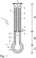
- inventive reformer tube 1 is divided into sections A (reaction chamber), B (outlet chamber) and C (manifold).
- Desulfurized natural gas together with reforming steam, enters the reaction chamber A arranged in the upper part of a casing tube 3 via an inlet line 2 .
- the jacket tube consists of a nickel-chromium steel, for example of the type G-X45NiCrNbTi3525.
- the inlet temperature of the feed gas is 600° C., and the space velocity, based on the catalyst volume, is typically 4000 to 5000 m N 3 /(m 3 h).
- the reformer tube is arranged in a vertical position with the open tube end of the casing tube 3 in the upper position and is heated from the outside by means of burners (not shown in 1 ).
- a closure device 4 for example a flanged-on cover, which can be opened for inspection processes and for filling or emptying the catalytic converter.
- the natural gas and the reforming steam After entering the jacket tube, the natural gas and the reforming steam enter a structured catalyst 5, which is composed of individual packing segments and, in terms of its structure, corresponds to that in FIG US 2012/0195801 A1 corresponds to the structured catalyst described. It has a specific surface area of 1100 m 2 /m 3 and is equipped with a nickel-containing active layer that is catalytically active for steam reforming.
- the structured catalyst is also designed such that a significant portion of the gas flow is deflected radially. As a result, part of the gas flow hits the inner wall of the reaction tube, which improves the radial heat transfer. However, the effect is limited, so that a further improvement in the radial heat transfer, as is achieved with the reformer tube according to the invention, is advantageous.
- the feeds then flow up through the structured catalyst where the endothermic steam reforming reaction takes place.
- the partially converted natural gas which also contains unreacted methane in addition to carbon oxides and hydrogen, enters a free space 8 after leaving the structured catalyst, which is attached to the closed one Pipe end 4 of the jacket pipe is arranged.
- the partially converted feed gas stream then enters the inlet end of a straight heat exchanger tube 9 which is arranged within the catalyst bed. The gas stream flowing through the heat exchanger tube 9 gives off part of its sensible heat in countercurrent to the catalyst bed and the feed gas stream flowing through it.
- the heat exchanger tubes are made of materials with good resistance to metal dusting corrosion such as Alloy 601, 602 CA, 617, 690, 692, 693, HR 160, HR 214, alloys containing copper or so-called multilayer materials in which the tubes are coated with tin Nickel or aluminium-nickel alloys are coated.
- the exit ends of the heat exchanger tube are provided with an anti-corrosion layer on the inside and on the parts that pass through the separating plate on the outside as well. In the present example, this is an aluminum diffusion layer.
- the synthesis gas product stream After passing through the heat exchanger tube, the synthesis gas product stream enters exit chamber B.
- the outlet end of the heat exchanger tube 9 is passed through a separating plate 6 and fixed in this way. It then opens out into an inner tube 10 on the outlet side, which represents the connection between the heat exchanger tube 9 and a collecting line 11 .
- the inner tube is also made from one of the above-mentioned metallic materials and its inner wall and preferably also its outer wall are equipped with an aluminum diffusion layer as an anti-corrosion layer.
- an inner tube made of a ceramic material can also be used.
- a gas-permeable insulating material 12 is attached between the outer wall of the inner tube and the inner wall of the jacket tube.
- Fiber-based insulating materials but also inherently dimensionally stable ceramic moldings can be used for this. The latter are particularly advantageous because they can be assembled and disassembled particularly easily. Due to their dimensional stability, they can be easily placed in the annular space between the jacket pipe and the inner pipe during assembly without the need for special fasteners.
- the inside of the collecting line 11 is provided with insulating material 13 and/or a corrosion-resistant, for example ceramic, coating 14 which has increased resistance to metal dusting corrosion.
- the synthesis gas product stream is discharged from the reformer tube 1 via the collecting line and is fed to further processing. Depending on the intended use of the synthesis gas product, this can include carbon monoxide conversion, gas scrubbing to remove carbon dioxide, pressure swing adsorption to remove hydrogen and other work-up stages.
- the examples according to the invention are based on configurations of the reformer with bayonet tubes with a structured catalyst.
- the steam export is between 0 and 0.8 kg of steam per m N 3 of hydrogen produced.
- the reforming temperature is above 900.degree.
- the reformer tubes should be equipped as normal tubes with a straight passage, ie without internal heat recovery, and with catalyst pellets or with a structured catalyst.
- the state of the art recommends, for example according to the patent publications EP 1944269 B1 or US7501078B2 , a design with a reduced number of reformer tubes to achieve savings.
- Embodiments of steam reforming processes according to the invention without steam export or with low steam export (0 to 0.3 kg export steam per m N 3 of hydrogen produced) have the following features, which aim to increase the reformer efficiency and the reforming temperature as much as possible:
- the tube diameter is reduced and the number of reformer tubes is increased in order to overcome mechanical limitations. This allows the reforming temperature to be increased beyond 900 °C.
- the reduction of the tube diameter is possible thanks to the use of the structured catalyst, which can be adapted to the small diameter and annulus.
- the increased reforming temperature shifts the reaction equilibrium in the direction of higher hydrocarbon conversion in the reformer, at the same time increasing the efficiency of the reformer (reformer efficiency) and reducing the total natural gas consumption, although the exchange area for heat exchange has decreased compared to the reference case in column 2.
- the cases shown in columns 2 and 3 are limited in terms of the maximum achievable reforming temperature due to the high tube thickness of the reformer tubes.
Priority Applications (5)
| Application Number | Priority Date | Filing Date | Title |
|---|---|---|---|
| EP21020475.6A EP4155259A1 (fr) | 2021-09-22 | 2021-09-22 | Procédé de production de gaz de synthèse à exportation réduite de vapeur |
| AU2022228210A AU2022228210A1 (en) | 2021-09-22 | 2022-09-09 | Process for producing synthesis gas with reduced steam export |
| CN202211142222.8A CN115888562A (zh) | 2021-09-22 | 2022-09-20 | 蒸汽输出减少的合成气的生产方法 |
| KR1020220118401A KR20230042654A (ko) | 2021-09-22 | 2022-09-20 | 수증기 방출을 감소시킨 합성 가스 제조 공정 |
| US17/949,410 US20230089656A1 (en) | 2021-09-22 | 2022-09-21 | Process for producing synthesis gas with reduced steam export |
Applications Claiming Priority (1)
| Application Number | Priority Date | Filing Date | Title |
|---|---|---|---|
| EP21020475.6A EP4155259A1 (fr) | 2021-09-22 | 2021-09-22 | Procédé de production de gaz de synthèse à exportation réduite de vapeur |
Publications (1)
| Publication Number | Publication Date |
|---|---|
| EP4155259A1 true EP4155259A1 (fr) | 2023-03-29 |
Family
ID=77951433
Family Applications (1)
| Application Number | Title | Priority Date | Filing Date |
|---|---|---|---|
| EP21020475.6A Pending EP4155259A1 (fr) | 2021-09-22 | 2021-09-22 | Procédé de production de gaz de synthèse à exportation réduite de vapeur |
Country Status (5)
| Country | Link |
|---|---|
| US (1) | US20230089656A1 (fr) |
| EP (1) | EP4155259A1 (fr) |
| KR (1) | KR20230042654A (fr) |
| CN (1) | CN115888562A (fr) |
| AU (1) | AU2022228210A1 (fr) |
Families Citing this family (3)
| Publication number | Priority date | Publication date | Assignee | Title |
|---|---|---|---|---|
| KR102605432B1 (ko) | 2016-11-09 | 2023-11-24 | 8 리버스 캐피탈, 엘엘씨 | 통합 수소 생산을 구비하는 동력 생산을 위한 시스템들 및 방법들 |
| US11859517B2 (en) | 2019-06-13 | 2024-01-02 | 8 Rivers Capital, Llc | Power production with cogeneration of further products |
| WO2023089571A1 (fr) | 2021-11-18 | 2023-05-25 | 8 Rivers Capital, Llc | Procédé de production d'hydrogène |
Citations (8)
| Publication number | Priority date | Publication date | Assignee | Title |
|---|---|---|---|---|
| EP0025308B1 (fr) | 1979-09-06 | 1984-07-11 | Imperial Chemical Industries Plc | Procédé et dispositif pour faire réagir catalytiquement de la vapeur avec des hydrocarbures dans des conditions endothermiques |
| EP0305203A2 (fr) | 1987-08-27 | 1989-03-01 | Haldor Topsoe A/S | Procédé pour exécuter des réactions chimiques hétérogènes catalytiques |
| EP0855366A1 (fr) | 1997-01-22 | 1998-07-29 | Haldor Topsoe A/S | Production de gaz de synthèse par réformage à la vapeur utilisant un hardware catalysé |
| EP1857174A1 (fr) | 2006-05-17 | 2007-11-21 | Air Products and Chemicals, Inc. | Réacteur avec structure expansible fournissant un transfert thermique amélioré |
| EP1944269A1 (fr) | 2007-01-10 | 2008-07-16 | Air Products and Chemicals, Inc. | Processus de génération de gaz de synthèse utilisant un emballage structuré catalysé |
| US20120195801A1 (en) | 2011-01-28 | 2012-08-02 | Catacel Corporation | Stackable structural reactors |
| DE102011118217A1 (de) * | 2011-11-11 | 2013-05-16 | L'Air Liquide, Société Anonyme pour l'Etude et l'Exploitation des Procédés Georges Claude | Reformerrohr mit internem Wärmeaustausch |
| DE102016120167A1 (de) * | 2016-09-14 | 2018-03-15 | L'Air Liquide, Société Anonyme pour l'Etude et l'Exploitation des Procédés Georges Claude | Reformerrohr mit strukturiertem Katalysator und verbessertem Wärmehaushalt |
-
2021
- 2021-09-22 EP EP21020475.6A patent/EP4155259A1/fr active Pending
-
2022
- 2022-09-09 AU AU2022228210A patent/AU2022228210A1/en active Pending
- 2022-09-20 KR KR1020220118401A patent/KR20230042654A/ko unknown
- 2022-09-20 CN CN202211142222.8A patent/CN115888562A/zh active Pending
- 2022-09-21 US US17/949,410 patent/US20230089656A1/en active Pending
Patent Citations (11)
| Publication number | Priority date | Publication date | Assignee | Title |
|---|---|---|---|---|
| EP0025308B1 (fr) | 1979-09-06 | 1984-07-11 | Imperial Chemical Industries Plc | Procédé et dispositif pour faire réagir catalytiquement de la vapeur avec des hydrocarbures dans des conditions endothermiques |
| EP0305203A2 (fr) | 1987-08-27 | 1989-03-01 | Haldor Topsoe A/S | Procédé pour exécuter des réactions chimiques hétérogènes catalytiques |
| EP0855366A1 (fr) | 1997-01-22 | 1998-07-29 | Haldor Topsoe A/S | Production de gaz de synthèse par réformage à la vapeur utilisant un hardware catalysé |
| EP1857174A1 (fr) | 2006-05-17 | 2007-11-21 | Air Products and Chemicals, Inc. | Réacteur avec structure expansible fournissant un transfert thermique amélioré |
| EP1944269A1 (fr) | 2007-01-10 | 2008-07-16 | Air Products and Chemicals, Inc. | Processus de génération de gaz de synthèse utilisant un emballage structuré catalysé |
| US7501078B2 (en) | 2007-01-10 | 2009-03-10 | Air Products And Chemicals, Inc. | Process for generating synthesis gas using catalyzed structured packing |
| EP1944269B1 (fr) | 2007-01-10 | 2010-09-01 | Air Products and Chemicals, Inc. | Processus de génération de gaz de synthèse utilisant un emballage structuré catalysé |
| US20120195801A1 (en) | 2011-01-28 | 2012-08-02 | Catacel Corporation | Stackable structural reactors |
| DE102011118217A1 (de) * | 2011-11-11 | 2013-05-16 | L'Air Liquide, Société Anonyme pour l'Etude et l'Exploitation des Procédés Georges Claude | Reformerrohr mit internem Wärmeaustausch |
| WO2013068416A1 (fr) | 2011-11-11 | 2013-05-16 | L'Air Liquide, Société Anonyme pour l'Etude et l'Exploitation des Procédés Georges Claude | Tube de reformage à échange de chaleur interne |
| DE102016120167A1 (de) * | 2016-09-14 | 2018-03-15 | L'Air Liquide, Société Anonyme pour l'Etude et l'Exploitation des Procédés Georges Claude | Reformerrohr mit strukturiertem Katalysator und verbessertem Wärmehaushalt |
Non-Patent Citations (2)
| Title |
|---|
| AUFSATZ VON M. GRÜNEWALDU. KUNZ: "Strukturierte Katalysatoren als Bausteine multifunktionaler Reaktoren", CHEMIE INGENIEUR TECHNIK, vol. 79, no. 9, 2007 |
| WIE, ULLMANN'S ENCYCLOPEDIA OF INDUSTRIAL CHEMISTRY, 1998 |
Also Published As
| Publication number | Publication date |
|---|---|
| US20230089656A1 (en) | 2023-03-23 |
| AU2022228210A1 (en) | 2023-04-06 |
| CN115888562A (zh) | 2023-04-04 |
| KR20230042654A (ko) | 2023-03-29 |
Similar Documents
| Publication | Publication Date | Title |
|---|---|---|
| EP3296255A1 (fr) | Tube de reformage comprenant un catalyseur structuré et gestion thermique améliorée | |
| EP4155259A1 (fr) | Procédé de production de gaz de synthèse à exportation réduite de vapeur | |
| EP2776365B1 (fr) | Tube de reformage à échange de chaleur interne | |
| EP3497058B1 (fr) | Dispositif de synthèse et procédé de production d'un produit | |
| DE60216859T2 (de) | Methan-Dampfreformierungsofen mit Prereformer der mittels Konvektion geheizt wird | |
| DE69736438T2 (de) | Methode zur dampfreformierung von kohlenwasserstoffen | |
| EP3401299B1 (fr) | Réacteur destiné à effectuer des réactions d'équilibre exothermiques | |
| EP1425244B1 (fr) | Unite de reformage compacte destinee a la production d'hydrogene a partir d'hydrocarbures gazeux dans la gamme de petite puissance | |
| DE112005000390T5 (de) | Integrierte Brennstoffverarbeitungsanlage für eine dezentrale Wasserstoffproduktion | |
| CN1196330A (zh) | 通过采用催化成品、蒸汽重整生产合成气 | |
| EP0687648A1 (fr) | Réformage de méthanol en deux étapes | |
| WO2016207342A1 (fr) | Optimisation du bilan thermique dans des reformeurs grâce à l'utilisation de supports de catalyseurs métalliques | |
| EP0787679A1 (fr) | Procédé et dispositif pour la récupération d'un gaz riche en hydrogène et pauvre en monoxyde de carbone | |
| EP3266739B1 (fr) | Tube de reformage protege contre la corrosion comprenant un echangeur thermique interne | |
| DE2929300A1 (de) | Reaktor zur durchfuehrung katalytischer endothermer oder exothermer reaktionen | |
| DE3832257A1 (de) | Katalysator-festbettreaktor | |
| DE10333523B4 (de) | Wärmetauscheranordnung zur Übertragung von Reformatenergie an Dampf und Luft | |
| DE112005000654T5 (de) | Katalytischer Reaktor | |
| EP3401300B1 (fr) | Procédé pour la production du méthanol | |
| DE102004063151A1 (de) | Reformer für eine Brennstoffzelle | |
| WO2013135668A1 (fr) | Système de réacteurs chimiques comprenant un réacteur d'écoulement axial pourvu de surfaces de chauffage et intermédiaires. | |
| EP1427668A1 (fr) | Dispositif de production d'hydrogene | |
| EP3135370B1 (fr) | Reacteur destine a produire du gaz de synthese par reformage a la vapeur | |
| WO1999044734A1 (fr) | Appareil dote d'un ecoulement traversant et procede de fonctionnement d'un tel appareil | |
| DE10209886A1 (de) | Vorrichtung sowie Verfahren zur Reformierung von Kohlenwasserstoffen aus einem Einsatzgas |
Legal Events
| Date | Code | Title | Description |
|---|---|---|---|
| PUAI | Public reference made under article 153(3) epc to a published international application that has entered the european phase |
Free format text: ORIGINAL CODE: 0009012 |
|
| STAA | Information on the status of an ep patent application or granted ep patent |
Free format text: STATUS: THE APPLICATION HAS BEEN PUBLISHED |
|
| AK | Designated contracting states |
Kind code of ref document: A1 Designated state(s): AL AT BE BG CH CY CZ DE DK EE ES FI FR GB GR HR HU IE IS IT LI LT LU LV MC MK MT NL NO PL PT RO RS SE SI SK SM TR |
|
| RAP3 | Party data changed (applicant data changed or rights of an application transferred) |
Owner name: L'AIR LIQUIDE, SOCIETE ANONYME POUR L'ETUDE ET L'EXPLOITATION DES PROCEDES GEORGES CLAUDE |
|
| STAA | Information on the status of an ep patent application or granted ep patent |
Free format text: STATUS: REQUEST FOR EXAMINATION WAS MADE |
|
| 17P | Request for examination filed |
Effective date: 20230929 |
|
| RBV | Designated contracting states (corrected) |
Designated state(s): AL AT BE BG CH CY CZ DE DK EE ES FI FR GB GR HR HU IE IS IT LI LT LU LV MC MK MT NL NO PL PT RO RS SE SI SK SM TR |