EP4155103A1 - Système et procédé d'installation de batteries de traction pour un véhicule - Google Patents
Système et procédé d'installation de batteries de traction pour un véhicule Download PDFInfo
- Publication number
- EP4155103A1 EP4155103A1 EP22205395.1A EP22205395A EP4155103A1 EP 4155103 A1 EP4155103 A1 EP 4155103A1 EP 22205395 A EP22205395 A EP 22205395A EP 4155103 A1 EP4155103 A1 EP 4155103A1
- Authority
- EP
- European Patent Office
- Prior art keywords
- bracket member
- traction battery
- slider
- vehicle
- rear bracket
- Prior art date
- Legal status (The legal status is an assumption and is not a legal conclusion. Google has not performed a legal analysis and makes no representation as to the accuracy of the status listed.)
- Pending
Links
Images


Classifications
-
- B—PERFORMING OPERATIONS; TRANSPORTING
- B60—VEHICLES IN GENERAL
- B60K—ARRANGEMENT OR MOUNTING OF PROPULSION UNITS OR OF TRANSMISSIONS IN VEHICLES; ARRANGEMENT OR MOUNTING OF PLURAL DIVERSE PRIME-MOVERS IN VEHICLES; AUXILIARY DRIVES FOR VEHICLES; INSTRUMENTATION OR DASHBOARDS FOR VEHICLES; ARRANGEMENTS IN CONNECTION WITH COOLING, AIR INTAKE, GAS EXHAUST OR FUEL SUPPLY OF PROPULSION UNITS IN VEHICLES
- B60K1/00—Arrangement or mounting of electrical propulsion units
- B60K1/04—Arrangement or mounting of electrical propulsion units of the electric storage means for propulsion
-
- H—ELECTRICITY
- H01—ELECTRIC ELEMENTS
- H01M—PROCESSES OR MEANS, e.g. BATTERIES, FOR THE DIRECT CONVERSION OF CHEMICAL ENERGY INTO ELECTRICAL ENERGY
- H01M50/00—Constructional details or processes of manufacture of the non-active parts of electrochemical cells other than fuel cells, e.g. hybrid cells
- H01M50/20—Mountings; Secondary casings or frames; Racks, modules or packs; Suspension devices; Shock absorbers; Transport or carrying devices; Holders
- H01M50/249—Mountings; Secondary casings or frames; Racks, modules or packs; Suspension devices; Shock absorbers; Transport or carrying devices; Holders specially adapted for aircraft or vehicles, e.g. cars or trains
-
- B—PERFORMING OPERATIONS; TRANSPORTING
- B60—VEHICLES IN GENERAL
- B60K—ARRANGEMENT OR MOUNTING OF PROPULSION UNITS OR OF TRANSMISSIONS IN VEHICLES; ARRANGEMENT OR MOUNTING OF PLURAL DIVERSE PRIME-MOVERS IN VEHICLES; AUXILIARY DRIVES FOR VEHICLES; INSTRUMENTATION OR DASHBOARDS FOR VEHICLES; ARRANGEMENTS IN CONNECTION WITH COOLING, AIR INTAKE, GAS EXHAUST OR FUEL SUPPLY OF PROPULSION UNITS IN VEHICLES
- B60K1/00—Arrangement or mounting of electrical propulsion units
- B60K1/04—Arrangement or mounting of electrical propulsion units of the electric storage means for propulsion
- B60K2001/0405—Arrangement or mounting of electrical propulsion units of the electric storage means for propulsion characterised by their position
- B60K2001/0438—Arrangement under the floor
-
- B—PERFORMING OPERATIONS; TRANSPORTING
- B60—VEHICLES IN GENERAL
- B60K—ARRANGEMENT OR MOUNTING OF PROPULSION UNITS OR OF TRANSMISSIONS IN VEHICLES; ARRANGEMENT OR MOUNTING OF PLURAL DIVERSE PRIME-MOVERS IN VEHICLES; AUXILIARY DRIVES FOR VEHICLES; INSTRUMENTATION OR DASHBOARDS FOR VEHICLES; ARRANGEMENTS IN CONNECTION WITH COOLING, AIR INTAKE, GAS EXHAUST OR FUEL SUPPLY OF PROPULSION UNITS IN VEHICLES
- B60K1/00—Arrangement or mounting of electrical propulsion units
- B60K1/04—Arrangement or mounting of electrical propulsion units of the electric storage means for propulsion
- B60K2001/0455—Removal or replacement of the energy storages
- B60K2001/0461—Removal or replacement of the energy storages from the side
-
- B—PERFORMING OPERATIONS; TRANSPORTING
- B60—VEHICLES IN GENERAL
- B60K—ARRANGEMENT OR MOUNTING OF PROPULSION UNITS OR OF TRANSMISSIONS IN VEHICLES; ARRANGEMENT OR MOUNTING OF PLURAL DIVERSE PRIME-MOVERS IN VEHICLES; AUXILIARY DRIVES FOR VEHICLES; INSTRUMENTATION OR DASHBOARDS FOR VEHICLES; ARRANGEMENTS IN CONNECTION WITH COOLING, AIR INTAKE, GAS EXHAUST OR FUEL SUPPLY OF PROPULSION UNITS IN VEHICLES
- B60K1/00—Arrangement or mounting of electrical propulsion units
- B60K1/04—Arrangement or mounting of electrical propulsion units of the electric storage means for propulsion
- B60K2001/0455—Removal or replacement of the energy storages
- B60K2001/0472—Removal or replacement of the energy storages from below
-
- B—PERFORMING OPERATIONS; TRANSPORTING
- B60—VEHICLES IN GENERAL
- B60K—ARRANGEMENT OR MOUNTING OF PROPULSION UNITS OR OF TRANSMISSIONS IN VEHICLES; ARRANGEMENT OR MOUNTING OF PLURAL DIVERSE PRIME-MOVERS IN VEHICLES; AUXILIARY DRIVES FOR VEHICLES; INSTRUMENTATION OR DASHBOARDS FOR VEHICLES; ARRANGEMENTS IN CONNECTION WITH COOLING, AIR INTAKE, GAS EXHAUST OR FUEL SUPPLY OF PROPULSION UNITS IN VEHICLES
- B60K1/00—Arrangement or mounting of electrical propulsion units
- B60K1/04—Arrangement or mounting of electrical propulsion units of the electric storage means for propulsion
- B60K2001/0455—Removal or replacement of the energy storages
- B60K2001/0494—Removal or replacement of the energy storages with arrangements for sliding
-
- B—PERFORMING OPERATIONS; TRANSPORTING
- B60—VEHICLES IN GENERAL
- B60Y—INDEXING SCHEME RELATING TO ASPECTS CROSS-CUTTING VEHICLE TECHNOLOGY
- B60Y2200/00—Type of vehicle
- B60Y2200/10—Road Vehicles
- B60Y2200/14—Trucks; Load vehicles, Busses
-
- B—PERFORMING OPERATIONS; TRANSPORTING
- B60—VEHICLES IN GENERAL
- B60Y—INDEXING SCHEME RELATING TO ASPECTS CROSS-CUTTING VEHICLE TECHNOLOGY
- B60Y2200/00—Type of vehicle
- B60Y2200/10—Road Vehicles
- B60Y2200/14—Trucks; Load vehicles, Busses
- B60Y2200/142—Heavy duty trucks
-
- B—PERFORMING OPERATIONS; TRANSPORTING
- B60—VEHICLES IN GENERAL
- B60Y—INDEXING SCHEME RELATING TO ASPECTS CROSS-CUTTING VEHICLE TECHNOLOGY
- B60Y2306/00—Other features of vehicle sub-units
- B60Y2306/01—Reducing damages in case of crash, e.g. by improving battery protection
-
- Y—GENERAL TAGGING OF NEW TECHNOLOGICAL DEVELOPMENTS; GENERAL TAGGING OF CROSS-SECTIONAL TECHNOLOGIES SPANNING OVER SEVERAL SECTIONS OF THE IPC; TECHNICAL SUBJECTS COVERED BY FORMER USPC CROSS-REFERENCE ART COLLECTIONS [XRACs] AND DIGESTS
- Y02—TECHNOLOGIES OR APPLICATIONS FOR MITIGATION OR ADAPTATION AGAINST CLIMATE CHANGE
- Y02E—REDUCTION OF GREENHOUSE GAS [GHG] EMISSIONS, RELATED TO ENERGY GENERATION, TRANSMISSION OR DISTRIBUTION
- Y02E60/00—Enabling technologies; Technologies with a potential or indirect contribution to GHG emissions mitigation
- Y02E60/10—Energy storage using batteries
Definitions
- the invention relates to a system for installation of traction batteries for a vehicle having a chassis comprising at least one load-carrying frame member.
- the invention also relates to a battery arrangement comprising such a system.
- the invention furthermore relates to a vehicle and a method of installation of traction batteries.
- the invention can be applied in heavy-duty vehicles, such as trucks, buses and construction equipment. Although the invention will be described with respect to a truck, the invention is not restricted to this particular vehicle, but may also be used in other vehicles such as passenger cars.
- WO 2017/207970 A1 discloses a mounting arrangement for mounting a range extender or a battery storage to a vehicle.
- the mounting arrangement comprises mounting brackets for securing a battery to a cage-like frame.
- the battery can be placed in the frame which can then be slid along two bracket members.
- the cage-like frame functions similarly to a drawer being attached with rails to a chest of drawers.
- the battery must be lowered into the frame, and then the frame with the battery may be slid into place. When the battery is to be replaced it must be lifted up from the cage-like frame.
- An object of the invention is to provide a system which alleviates the drawbacks of the prior art.
- the object is achieved by a system for installation of traction batteries for a vehicle having a chassis comprising at least one load-carrying frame member, in accordance with claim 1.
- the system comprises:
- the first and second sliders are attached to the traction battery, and only thereafter will they be brought to mate with the sliding surfaces of the bracket members.
- front and rear relate to directional configurations of a vehicle.
- front is towards the normal driving direction
- rear is towards the direction in which the vehicle is operated when in reverse drive.
- the cab of a truck is normally located at the front of the truck.
- the system comprises a receiving structure, wherein the receiving structure comprises said front bracket member, said rear bracket member and a stabilizing element, wherein the front bracket member and the rear bracket member are spaced apart and interconnected by the stabilizing element, wherein the receiving structure is adapted to be secured to a frame member of the vehicle and adapted to receive a traction battery between the front bracket member and the rear bracket member.
- a stabilizing element makes the system as such stronger, and allows a more secure holding of the traction battery.
- each one of the front bracket member and the rear bracket member comprises a securing portion for securing the bracket member to a frame member of the vehicle, and at least one arm portion projecting from the securing portion.
- the arm portions are advantageous in that they provide front/rear limitations to the traction battery, and apart from a guiding function also provides some amount of protection to the traction battery.
- the stabilizing element may suitably extend between the securing portions of the bracket members. In some exemplary embodiments. The stabilizing element may similarly to the securing portions be used for securing the receiving structure to a frame member of the vehicle.
- an intermediate securing bracket located between the securing portions of the front and rear bracket members, which intermediate securing bracket may be used for connecting the stabilizing element to a frame member of the vehicle.
- the stabilizing element may extend between the arm portions.
- each one of the front bracket member and the rear bracket member comprises two vertically spaced arm portions, namely a lower arm portion and an upper arm portion, both projecting from the securing portion, wherein each one of the lower arm portion and the upper arm portion is provided with said sliding surface.
- the lower arm portion of the front bracket member and the lower arm portion of the rear bracket member are adapted to slidingly receive a first traction battery to which said first and second sliders have been connected, the system further comprising a third and a fourth slider, wherein the upper arm portion of the front bracket member and the upper arm portion of the rear bracket member are adapted to slidingly receive a second traction battery to which said third and fourth sliders have been connected.
- Each bracket member will thus have a generally U-shaped configuration, wherein the securing portion will form the central base of the U-shape, and the arm portions will form the legs of the U-shape.
- the one or more arms of a bracket member may suitably have a substantially horizontal extension, and may suitably project substantially perpendicularly to the frame member to which the bracket member is to be attached (and therefore it may also project substantially perpendicularly to a surface of the securing portion of the bracket member, which surface is configured to mate with the frame member).
- the system comprises a crash protection structure adapted to be mounted to a free end of the at least one arm portion of each one of the front bracket member and the rear bracket member when a traction battery has been received therebetween, such that the traction battery becomes enclosed by the frame member of the vehicle, the front bracket member, the rear bracket member and the crash protection structure.
- each arm portion has a longitudinal extension projecting from the securing portion to its free end, wherein, when the crash protection structure is mounted to the free end of the arm portion, the main extension of the crash protection structure lies in a geometrical plane which is perpendicular to the longitudinal extension of the arm portion. Similarly to above, this provides extra protection to the traction battery, in particular to lateral impact load.
- the system comprises a protecting bottom plate adapted to be joined to a lower side of a traction battery. This is advantageous since it protects the traction battery from below.
- said protecting bottom plate is adapted to be joined to a lower side of the first traction battery, the system further comprising a horizontal side collision protection plate adapted to be joined to a lower side of the second traction battery.
- a horizontal side collision protection plate adapted to be joined to a lower side of the second traction battery.
- one or both of the protecting bottom plate and the horizontal side collision protection plate may have a bent upwardly extending edge at the side configured to be farthest away from the frame member of the vehicle (and therefore farthest away from the securing portions of the bracket members).
- Such a bent upwardly extending edge (which may form an L-shaped cross section with the horizontally extending main portion of the plate) may be used for further securing the crash protection structure.
- the crash protection structure may be secured by fastening means, such as bolts, rivets, etc. to such a bent upwardly extending edge of said protecting bottom plate and/or said horizontal side collision protection plate.
- the system comprises a bushing, wherein the first slider is adapted to be connected to the front side of the traction battery via said bushing.
- the system comprises two bushings, wherein said bushing is a first bushing for connecting said first traction battery to the first slider, the system further comprising a second bushing for connecting said second traction battery to said third slider.
- said bushing is a first bushing for connecting said first traction battery to the first slider
- said system further comprising a second bushing for connecting said second traction battery to said third slider.
- a battery arrangement comprising a system according to the first aspect (including any embodiments thereof) and a traction battery, wherein said first slider is connected, or is adapted to be connected, to a front side of the traction battery, and wherein said second slider is connected, or is adapted to be connected, to an opposite rear side of the traction battery.
- a vehicle comprising a chassis comprising at least one load-carrying frame member, and a system according to the first aspect (including any embodiments thereof) and a battery arrangement according to the second aspect (including any embodiments thereof), wherein the front bracket member is secured to and projects from the frame member, and the rear bracket member is secured to and projects from the frame member, spaced apart from the front bracket member.
- a method for installation of traction batteries to a vehicle having a chassis comprising at least one load-carrying frame member to which a front bracket member and a rear bracket member are secured to and projects from, the rear bracket member being spaced apart from the front bracket member, for receiving a traction battery between the front bracket member and the rear bracket member, wherein each one of the front bracket member and the rear bracket member comprises a respective sliding surface, the method comprising the steps of:
- the front bracket member, rear bracket member, first slider and second slider are included in a system according to the first aspect (including any embodiments thereof).
- the system according to Example 1, comprising a receiving structure, wherein the receiving structure comprises said front bracket member, said rear bracket member and a stabilizing element, wherein the front bracket member and the rear bracket member are spaced apart and interconnected by the stabilizing element, wherein the receiving structure is adapted to be secured to a frame member of the vehicle and adapted to receive a traction battery between the front bracket member and the rear bracket member.
- each one of the front bracket member and the rear bracket member comprises:
- each one of the front bracket member and the rear bracket member comprises two vertically spaced arm portions, namely a lower arm portion and an upper arm portion, both projecting from the securing portion, wherein each one of the lower arm portion and the upper arm portion is provided with said sliding surface.
- the system according to any one of Examples 3-5 comprising a crash protection structure adapted to be mounted to a free end of the at least one arm portion of each one of the front bracket member and the rear bracket member when a traction battery has been received therebetween, such that the traction battery becomes enclosed by the frame member of the vehicle, the front bracket member, the rear bracket member and the crash protection structure.
- Example 8 when dependent on Example 5, wherein said protecting bottom plate is adapted to be joined to a lower side of the first traction battery, the system further comprising a horizontal side collision protection plate adapted to be joined to a lower side of the second traction battery.
- Example 10 when dependent on Example 5, comprising two bushings, wherein said bushing is a first bushing for connecting said first traction battery to the first slider, the system further comprising a second bushing for connecting said second traction battery to said third slider.
- a battery arrangement comprising:
- a vehicle comprising:
- Example 14 wherein the front bracket member, rear bracket member, first slider and second slider are included in a system according to any one of Examples 1-11.
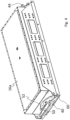
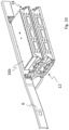
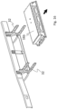
- Fig. 1 is a schematic illustration of a vehicle 2 comprising a system 10 according to at least one exemplary embodiment of the invention.
- vehicle 2 is illustrated in the form of a truck, other types of vehicles, such as busses or construction equipment may be used with the inventive system 10.
- the truck comprises a cab 4 in which a driver may operate the vehicle 2.
- the vehicle 2 has a chassis comprising at least one load-carrying frame member 6.
- a longitudinal frame member 6 is here illustrated as extending in the direction from rear 7 to front 8 of the vehicle 2.
- the vehicle 2 may have two or more such frame members extending in parallel.
- the inventive system 10 comprises a front bracket member 12 and a rear bracket member 14, which have been secured to and project from the frame member 6 of the vehicle 2.
- the front bracket member 12 and the rear bracket member 14 are spaced apart in the longitudinal direction of the vehicle 2.
- the front bracket member 12 is, compared to the rear bracket member 14, located closer to the front 8 of the vehicle 2.
- the rear bracket member 14 is, compared to the front bracket member 12, located closer to the rear 6 of the vehicle 2.
- a traction battery 16 has been received by, and extends between, the front bracket member 12 and the rear bracket member 14.
- the traction battery 16 together with the system 10 form part of a battery arrangement 20, in accordance with at least one exemplary embodiment of the invention.
- the system 10, the battery arrangement 20, the vehicle 2 and the method of the present invention may have front and rear bracket members with only one arm portion for receiving only one traction battery.
- the front bracket member 12 and the rear bracket member 14 may each have a securing portion for securing the bracket member to the frame member 6 of the vehicle 2 and an arm portion projecting from the securing portion.
- the front bracket member 12 and the rear bracket member 14 may each have two vertically spaced arm portions (or even more) similarly to the other drawing figures.
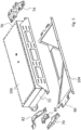
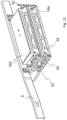
- Fig. 2 illustrates parts of a system for installation of traction batteries, in accordance with at least one exemplary embodiment of the invention.
- the system comprises a front bracket member 12 and a rear bracket member 14, both of which are adapted to be secured to a frame member 6 of a vehicle chassis.
- the front bracket member 12 and the rear bracket member 14 are illustrated in a secured state, i.e. they have been firmly fastened to the frame member 6.
- the front bracket member 12 is spaced apart from the rear bracket member 14, thereby defining a space 18 in which a traction battery may be received.
- the separating distance i.e. the extension of the space 18 in the longitudinal direction of the vehicle, substantially corresponds to the length of a traction battery to be received.
- the front bracket member 12 and the rear bracket member 14 are interconnected by a stabilizing element 22, providing extra strength and rigidity to the system.
- the stabilizing element 22 may be omitted.
- These three components 12, 14, 22 form part of a receiving structure 26.
- the receiving structure 26 is adapted to (and in Fig. 2 has been) secured to the frame member 6.
- the receiving structure 26 is adapted to receive a traction battery between the front bracket member 12 and the rear bracket member 14.
- Each one of the front bracket member 12 and the rear bracket member 14 comprises a securing portion 28 for securing the bracket to the frame member 6 and two arm portions 30, 32 projecting from the securing portion 28.
- a securing portion 28 for securing the bracket to the frame member 6
- arm portions 30, 32 projecting from the securing portion 28.
- only one arm portion projects from the securing portion 28.
- the two arm portions 30, 32 are vertically spaced, presenting a lower arm portion 30 and an upper arm portion 32. Both the lower arm portion 30 and the upper arm portion 32 project away from the securing portion 28.
- Each arm portion has a sliding surface 34.
- the sliding surface 34 is a top surface of the respective arm portion 30, 32.
- the sliding surface may be formed on a ledge.
- the securing portions 28 are secured by fastening means, such as bolts, rivets, to the frame member 6.
- the securing portions 28 may be welded to the frame member 6.
- an intermediate securing bracket 36 may be connected to the stabilizing element 22 (such as illustrated in Fig. 2 ).
- the intermediate securing bracket 36 may, similarly to the securing portions 28 be secured to the frame member 6, for instance, by means of fastening means, such as bolts, rivets, etc., or by welding.
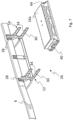
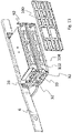
- Fig. 3 illustrates further parts of the system and a first traction battery 16a to which the further parts are connectable, in accordance with at least one exemplary embodiment of the invention.
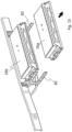
- Fig. 4 illustrates the first traction battery 16a after the further parts in Fig. 3 have been connected to the first traction battery 16a.
- Fig. 3 illustrates a first slider 40 adapted to be connected to a front side 42 of the traction battery 16a and a second slider 44 adapted to be connected to an opposite rear side 46 of the traction battery 16a.
- the first slider 40 is configured to be mated with the sliding surface 34 of the front bracket member 12 in Fig. 2
- the second slider 44 is configured to be mated with the sliding surface 34 of the rear bracket member 14 in Fig. 2 , after the first slider 40 and the second slider 44 have been connected to the first traction battery 16a.
- the first traction battery 16a is thereby enabled, by means of the connected first slider 40 and second slider 44, to be received by the front bracket member 12 and the rear bracket member 14 and be moved (for instance, slid) towards the frame member 6 of the vehicle.
- the system comprises sliders 40, 44 and sliding surfaces 34, it is not mandatory that the first traction battery 16a is slid into place, as it would be possible to for example lift the first traction battery 16a (with the sliders 40, 44 mounted to it) onto the sliding surfaces 34 of the front bracket member 12 and the rear bracket member 14.
- the first slider 40 is adapted to be connected to the front side 42 of the traction battery 16a via a bushing 48, which may for instance include two rubber parts 50 and a profiled element 52.
- the two rubber parts 50 and the first slider 40 may be connected to each other by screw connections.
- the profiled element 52 may in turn also have a screw connection to the rubber parts 50, and in addition be secured (e.g. by screw connection) to mounting plates 54 connected to the traction battery 16a.
- the mounting plates 54a are here illustrated as located on opposite lateral sides 56, 58 of the first traction battery 16a.
- the system may comprise a protecting bottom plate 60 adapted to be joined to a lower side of the first traction battery 16a via the first slider 40 and the second slider 44.
- the first slider 40 has a portion 62 which may be screw-connected to the protecting bottom plate 60.
- the first slider 40 will at least partly be clamped between the protecting bottom plate 60 and the rubber parts 50 under the profiled element 52. This will provide a degree of cushioning and resiliency/flexibility to the first slider 40.
- the second slider 44 is adapted to be rigidly connected to the protecting bottom plate 60, and to be rigidly connected to the mounting plates 54.
- the second slider 44 flexibly connected to the first traction battery 16a, similarly to the first slider 40.
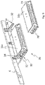
- Fig. 5 illustrates further parts of the system and a second traction battery 16b to which the further parts are connectable, in accordance with at least one exemplary embodiment of the invention.
- Fig. 6 illustrates the second traction battery 16b after the further parts in Fig. 5 have been connected to the second traction battery 16b. Said further parts substantially correspond to the further parts discussed in connection with Figs. 3 and 4 .
- the system further comprises a third slider 70 to be connected to a font side 72 of the second traction battery 16b and a fourth slider 74 to be connected to an opposite rear side 76 of the second traction battery 16b.
- the third slider 70 is connected to the second traction battery 16b via two rubber parts 80 and a profiled element 82, while the fourth slider 74 is rigidly connected to the second traction battery 16b.
- Figs. 7-14 illustrate a sequence in which the first traction battery 16a and the second traction battery 16b are installed in a vehicle.
- the first slider 40 and the second slider 44 have surfaces facing downwardly which are brought to mate with the sliding surfaces 34 of the lower arm portion 30 of the front bracket member 12 and the lower arm portion 30 of the rear bracket member 14, respectively, and moved into place (for instance, slid into place) close to the frame member 6. This is illustrated in Fig. 8 .
- the securing portions 28 of the front bracket member 12 and the rear bracket member 14, and/or the intermediate securing bracket 36 may provide abutment surfaces which limit lateral movement.
- the first slider 40 may be secured to the sliding surface 34 of the front bracket member 12, and the second slider 44 may be secured to the sliding surface 34 of the rear bracket member 14, for instance by means of screw-connections.
- the third slider 70 and the fourth slider 74 have surfaces facing downwardly which are brought to mate with the sliding surfaces 34 of the upper arm portion 32 of the front bracket member 12 and the upper arm portion 32 of the rear bracket member 14, respectively, and moved into place (for instance, slid into place) close to the frame member 6. This is illustrated in Fig. 10 .
- the system may comprise two vertical connectors 92, each having an upper connecting portion 94 and a lower connecting portion 96 which are configured and dimensioned to mate with the lateral end portions 98 of the upper arm portion 32 and lower arm portion 30, respectively, of one of the front and rear bracket members 12, 14.
- the connecting portions 94, 96 may suitably be secured to the arm portions 30, 32 by means of a screw-connection.
- Fig. 12 illustrates that the vertical connectors 92 have been secured to the arm portions 30, 32.
- the vertical connectors 92 have a length substantially corresponding to the vertical extension of the two mounted traction batteries (i.e. substantially the thickness of the first traction battery 16a plus the thickness of the second traction battery 16b).
- Fig. 13 illustrates that, in some exemplary embodiments, the system may comprise a crash protection structure 100 adapted to be mounted to the free ends of the arm portions 30, 32.
- free ends is meant the end of the arm portion which is not fixed or integrated with the securing portion 28.
- the free ends can receive other components, such as exemplified above, the free ends in the form of the lateral end portions 98 ( Fig. 11 ) may receive the vertical connectors 92.
- the crash protection structure 100 may thus be connected to the lateral end portions via the vertical connectors 92.
- the crash protection structure 100 has been illustrated as a substantially planar fence, grid or gate. However, other configurations of the crash protection structure 100 are conceivable, such as a sheet metal structure, with or without perforations.
- the traction batteries 16a, 16b are enclosed by the frame member 6 of the vehicle (on a lateral side), the front bracket member 12 (on the front side), the rear bracket member 14 (on the rear side) and the crash protection structure 100 (on the opposite lateral side).
- each arm portion 30, 32 has a longitudinal extension projecting from the securing portion 28 to its free end, wherein, when the crash protection structure 100 is mounted to the free ends of the arm portions 30, 32, the main extension of the crash protection structure 100 lies in a geometrical plane which is perpendicular to the longitudinal extension of the arm portions 30, 32.
- the crash protection structure 100 may in at least some exemplary embodiments (see Figs. 3 , 5 and 13 ) be connected to an upwardly bent edge 102 of the protecting bottom plate 60 and/or an upwardly bent edge 104 of the horizontal side collision protection plate 90.
- Such bent upwardly extending edges 102, 104 may, for instance, be provided with threaded holes for receiving a screw, bolt or the like for securing the crash protection structure 100.
- other fastening means such as snap connections are also conceivable.
- snap connections instead of screw connections for interconnecting other components of the system.
- Figs. 15-16 illustrate a sequence in which the first traction battery 16a and the second traction battery 16b are removed from the vehicle, for instance for being replaced by new traction batteries.
- the first traction battery 16a is suitably removed from the lower arm portions 30. This may for instance be by a sliding motion.
- second traction battery 16b is removed from the upper arm portions 32. This may, for instance, be by a sliding motion.
- a lifting motion is also conceivable.
- the removal of the first and second traction batteries 16a, 16b may, for instance, be carried out with the aid of a pallet lifter, a fork lift or any other appropriate tool or device.
- Fig. 17 shows a flow chart representation of a method 200 for installation of traction batteries, in accordance with at least one exemplary embodiment of the invention.
- the flow chart represents a method 200 for installation of traction batteries to a vehicle having a chassis comprising at least one load-carrying frame member to which a front bracket member and a rear bracket member are secured to and projects from, the rear bracket member being spaced apart from the front bracket member, for receiving a traction battery between the front bracket member and the rear bracket member, wherein each one of the front bracket member and the rear bracket member comprises a respective sliding surface, the method comprising the steps of:
- the first step S1 and the second step S2 may be performed in reverse order or may be performed simultaneously.
- the third step S3 and the fourth step S4 may be performed in the reverse order.
- the traction battery may be lifted towards the frame member and then mated with the bracket members.
- the traction battery may be first mated with the bracket members and then slid towards the frame member.
Landscapes
- Engineering & Computer Science (AREA)
- Chemical & Material Sciences (AREA)
- Combustion & Propulsion (AREA)
- Transportation (AREA)
- Mechanical Engineering (AREA)
- Aviation & Aerospace Engineering (AREA)
- Chemical Kinetics & Catalysis (AREA)
- Electrochemistry (AREA)
- General Chemical & Material Sciences (AREA)
- Battery Mounting, Suspending (AREA)
- Arrangement Or Mounting Of Propulsion Units For Vehicles (AREA)
Priority Applications (1)
| Application Number | Priority Date | Filing Date | Title |
|---|---|---|---|
| EP22205395.1A EP4155103A1 (fr) | 2019-04-04 | 2019-04-04 | Système et procédé d'installation de batteries de traction pour un véhicule |
Applications Claiming Priority (3)
| Application Number | Priority Date | Filing Date | Title |
|---|---|---|---|
| EP22205395.1A EP4155103A1 (fr) | 2019-04-04 | 2019-04-04 | Système et procédé d'installation de batteries de traction pour un véhicule |
| EP19717784.3A EP3946995B1 (fr) | 2019-04-04 | 2019-04-04 | Système et procédé d'installation de batteries de traction pour un véhicule |
| PCT/EP2019/058536 WO2020200459A1 (fr) | 2019-04-04 | 2019-04-04 | Système et procédé d'installation de batteries de traction pour un véhicule |
Related Parent Applications (2)
| Application Number | Title | Priority Date | Filing Date |
|---|---|---|---|
| EP19717784.3A Division-Into EP3946995B1 (fr) | 2019-04-04 | 2019-04-04 | Système et procédé d'installation de batteries de traction pour un véhicule |
| EP19717784.3A Division EP3946995B1 (fr) | 2019-04-04 | 2019-04-04 | Système et procédé d'installation de batteries de traction pour un véhicule |
Publications (1)
| Publication Number | Publication Date |
|---|---|
| EP4155103A1 true EP4155103A1 (fr) | 2023-03-29 |
Family
ID=66182500
Family Applications (2)
| Application Number | Title | Priority Date | Filing Date |
|---|---|---|---|
| EP22205395.1A Pending EP4155103A1 (fr) | 2019-04-04 | 2019-04-04 | Système et procédé d'installation de batteries de traction pour un véhicule |
| EP19717784.3A Active EP3946995B1 (fr) | 2019-04-04 | 2019-04-04 | Système et procédé d'installation de batteries de traction pour un véhicule |
Family Applications After (1)
| Application Number | Title | Priority Date | Filing Date |
|---|---|---|---|
| EP19717784.3A Active EP3946995B1 (fr) | 2019-04-04 | 2019-04-04 | Système et procédé d'installation de batteries de traction pour un véhicule |
Country Status (4)
| Country | Link |
|---|---|
| US (1) | US11938804B2 (fr) |
| EP (2) | EP4155103A1 (fr) |
| CN (2) | CN113661083B (fr) |
| WO (1) | WO2020200459A1 (fr) |
Families Citing this family (7)
| Publication number | Priority date | Publication date | Assignee | Title |
|---|---|---|---|---|
| CN113661083B (zh) * | 2019-04-04 | 2024-01-12 | 沃尔沃卡车集团 | 用于安装车辆的牵引电池的系统和方法 |
| EP3981631A1 (fr) * | 2020-10-12 | 2022-04-13 | Volvo Truck Corporation | Ensemble batterie |
| EP3988359B1 (fr) * | 2020-10-26 | 2023-08-30 | Volvo Truck Corporation | Système de montage de stockage d'énergie |
| CN112406499B (zh) * | 2020-11-30 | 2022-05-20 | 浙江吉利控股集团有限公司 | 一种横向拆装的半集成式动力电池箱系统及车辆 |
| DE102021107134A1 (de) * | 2021-03-23 | 2022-09-29 | Man Truck & Bus Se | Vorrichtung, System und Verfahren zur Halterung eines Speichers für Antriebsenergie |
| WO2023235417A1 (fr) * | 2022-05-31 | 2023-12-07 | Daimler Truck North America Llc | Structure de support pour batterie de véhicule électrique, ensemble doté de celle-ci et procédés de fabrication, d'intégration et d'utilisation de celle-ci |
| DE102022128747A1 (de) * | 2022-10-28 | 2022-12-29 | Daimler Truck AG | Nutzfahrzeug |
Citations (6)
| Publication number | Priority date | Publication date | Assignee | Title |
|---|---|---|---|---|
| DE2359054A1 (de) * | 1972-11-30 | 1974-07-11 | Sovel Vehicules Electr Ind Vil | Verfahren und vorrichtung zum schnellen wechseln der akkumulatorbatterien des zugantriebs an einem fahrzeug mit elektrischem eigenantrieb |
| WO2007029838A1 (fr) * | 2005-09-08 | 2007-03-15 | Toyota Jidosha Kabushiki Kaisha | Structure pour monter un dispositif de source d'énergie sur un véhicule |
| FR2942997A1 (fr) * | 2009-03-16 | 2010-09-17 | Peugeot Citroen Automobiles Sa | Vehicule electrique ou partiellement electrique equipe d'un mecanisme coulissant permettant de faciliter le remplacement de son dispositif de stockage d'energie electrique |
| DE202016103720U1 (de) * | 2015-07-30 | 2016-08-31 | Ford Global Technologies, Llc | Gleitender schützender Batteriestützträger |
| US9827840B2 (en) * | 2012-03-27 | 2017-11-28 | Aleees Eco Ark (Cayman) Co. Ltd. | Removable battery fixing assembly of electric vehicle and fixing method thereof |
| WO2017207970A1 (fr) | 2016-05-31 | 2017-12-07 | Arrival Limited | Châssis de véhicule électrique |
Family Cites Families (25)
| Publication number | Priority date | Publication date | Assignee | Title |
|---|---|---|---|---|
| KR20050099576A (ko) | 2004-04-10 | 2005-10-13 | 현대자동차주식회사 | 상용차의 차체구조 |
| JP2006123658A (ja) * | 2004-10-27 | 2006-05-18 | Mitsubishi Fuso Truck & Bus Corp | 車両の電子機器取付構造 |
| DE102006031461A1 (de) * | 2006-07-07 | 2008-01-10 | Jungheinrich Aktiengesellschaft | Batteriewechselsystem für ein batteriebetriebenes Flurförderzeug |
| FR2940637B1 (fr) | 2008-12-30 | 2011-08-19 | Renault Sas | Vehicule automobile equipe d'une batterie d'alimentation qui est amovible selon un mouvement vertical et dispositif d'installation et de depose d'une telle batterie. |
| DE102011109024A1 (de) | 2011-07-30 | 2013-01-31 | Man Truck & Bus Ag | Elektrisches Antriebsmodul für einFahrzeug, insbesondere Nutzfahrzeug |
| CN105083233B (zh) | 2015-05-29 | 2017-08-29 | 谢子聪 | 一种用于电动乘用车动力电池更换的锁紧系统 |
| KR20180025889A (ko) * | 2015-06-10 | 2018-03-09 | 배트스왑 인코포레이티드 | 배터리 교환 시스템 |
| US9517686B1 (en) * | 2015-09-03 | 2016-12-13 | Ford Global Technologies, Llc | Traction battery dual-stage mounting bracket |
| CN206406988U (zh) | 2016-12-30 | 2017-08-15 | 河南奔马股份有限公司 | 一种轻卡的组合式铝合金车架 |
| US10005350B1 (en) * | 2017-02-23 | 2018-06-26 | Ford Global Technologies, Llc | Traction battery securing assembly and method |
| CN109050233B (zh) | 2018-08-23 | 2020-06-23 | 杭州容大智造科技有限公司 | 一种电动物流车的电池安全更换装置 |
| WO2020074105A1 (fr) * | 2018-10-12 | 2020-04-16 | Volvo Truck Corporation | Agencement de bloc-batterie pour un véhicule |
| CN113302075B (zh) * | 2019-02-04 | 2024-05-10 | 沃尔沃卡车集团 | 具有电池结构的电动商用车辆 |
| CN113661083B (zh) * | 2019-04-04 | 2024-01-12 | 沃尔沃卡车集团 | 用于安装车辆的牵引电池的系统和方法 |
| US20230015644A1 (en) * | 2019-12-30 | 2023-01-19 | Volvo Truck Corporation | Modular electrical energy storage system structure, a method for providing electrical energy to an electrical motor of a vehicle and a vehicle comprising an electrical motor and the modular electrical energy storage system structure |
| KR20210115086A (ko) * | 2020-03-11 | 2021-09-27 | 현대자동차주식회사 | 차량의 배터리 탈거 시스템 |
| WO2021223848A1 (fr) * | 2020-05-05 | 2021-11-11 | Volvo Truck Corporation | Système de montage de systèmes de stockage d'énergie sur un véhicule |
| EP4146581A1 (fr) * | 2020-05-05 | 2023-03-15 | Volvo Truck Corporation | Agencement de verrouillage pour un système de montage pour un système de stockage d'énergie sur un véhicule |
| EP3925808A1 (fr) * | 2020-06-16 | 2021-12-22 | Volvo Truck Corporation | Agencement de châssis pour véhicule lourd électrifié et véhicule lourd électrifié |
| EP3925807B1 (fr) * | 2020-06-16 | 2024-01-24 | Volvo Truck Corporation | Agencement de support de module de batterie |
| DE102020121828A1 (de) * | 2020-08-20 | 2022-02-24 | Man Truck & Bus Se | Motorhalter und Fahrzeug mit einem ebensolchen Motorhalter |
| US11926207B2 (en) * | 2020-10-09 | 2024-03-12 | Hexagon Purus North America Holdings Inc. | Battery and auxiliary components for vehicle trailer |
| EP3981631A1 (fr) * | 2020-10-12 | 2022-04-13 | Volvo Truck Corporation | Ensemble batterie |
| EP3988359B1 (fr) * | 2020-10-26 | 2023-08-30 | Volvo Truck Corporation | Système de montage de stockage d'énergie |
| EP4052998A1 (fr) * | 2021-03-02 | 2022-09-07 | Volvo Truck Corporation | Structure de cadre pour véhicule |
-
2019
- 2019-04-04 CN CN201980095128.1A patent/CN113661083B/zh active Active
- 2019-04-04 EP EP22205395.1A patent/EP4155103A1/fr active Pending
- 2019-04-04 US US17/599,108 patent/US11938804B2/en active Active
- 2019-04-04 CN CN202311766960.4A patent/CN117863859A/zh active Pending
- 2019-04-04 EP EP19717784.3A patent/EP3946995B1/fr active Active
- 2019-04-04 WO PCT/EP2019/058536 patent/WO2020200459A1/fr unknown
Patent Citations (6)
| Publication number | Priority date | Publication date | Assignee | Title |
|---|---|---|---|---|
| DE2359054A1 (de) * | 1972-11-30 | 1974-07-11 | Sovel Vehicules Electr Ind Vil | Verfahren und vorrichtung zum schnellen wechseln der akkumulatorbatterien des zugantriebs an einem fahrzeug mit elektrischem eigenantrieb |
| WO2007029838A1 (fr) * | 2005-09-08 | 2007-03-15 | Toyota Jidosha Kabushiki Kaisha | Structure pour monter un dispositif de source d'énergie sur un véhicule |
| FR2942997A1 (fr) * | 2009-03-16 | 2010-09-17 | Peugeot Citroen Automobiles Sa | Vehicule electrique ou partiellement electrique equipe d'un mecanisme coulissant permettant de faciliter le remplacement de son dispositif de stockage d'energie electrique |
| US9827840B2 (en) * | 2012-03-27 | 2017-11-28 | Aleees Eco Ark (Cayman) Co. Ltd. | Removable battery fixing assembly of electric vehicle and fixing method thereof |
| DE202016103720U1 (de) * | 2015-07-30 | 2016-08-31 | Ford Global Technologies, Llc | Gleitender schützender Batteriestützträger |
| WO2017207970A1 (fr) | 2016-05-31 | 2017-12-07 | Arrival Limited | Châssis de véhicule électrique |
Also Published As
| Publication number | Publication date |
|---|---|
| CN117863859A (zh) | 2024-04-12 |
| US20220169104A1 (en) | 2022-06-02 |
| EP3946995B1 (fr) | 2023-02-15 |
| CN113661083A (zh) | 2021-11-16 |
| US11938804B2 (en) | 2024-03-26 |
| EP3946995A1 (fr) | 2022-02-09 |
| WO2020200459A1 (fr) | 2020-10-08 |
| CN113661083B (zh) | 2024-01-12 |
Similar Documents
| Publication | Publication Date | Title |
|---|---|---|
| US11938804B2 (en) | System and method for installation of traction batteries for a vehicle | |
| US20200282912A1 (en) | Modular rail and step system | |
| EP2957482B1 (fr) | Structure de châssis pour véhicule | |
| US8020925B2 (en) | Front structure of cab-over type vehicle | |
| EP3049261A1 (fr) | Structure avant de véhicule pour véhicule | |
| US7044504B2 (en) | Sub-assembly mounting system | |
| KR20170004028U (ko) | 전기트럭용 배터리 팩 장착 구조 | |
| US11981227B2 (en) | Device for installing traction batteries, a system and a vehicle | |
| CN115515816A (zh) | 用于车辆上的附件单元的安装系统 | |
| WO2015088421A1 (fr) | Agencement permettant de faciliter le montage d'un module de véhicule | |
| CN214355846U (zh) | 一种千斤顶装车结构 | |
| CN105459809A (zh) | 一种空滤器安装支架 | |
| US20190382036A1 (en) | Underfloor device of railway vehicle | |
| CN103029570A (zh) | 一种汽车散热器安装架及散热器总成安装结构 | |
| CN101446095B (zh) | 举升缸托架组件及制造方法 | |
| US20230322069A1 (en) | Mounting assembly attaching power supply to vehicle | |
| CN115027554B (zh) | 一种前车架总成结构及混合动力汽车 | |
| CN215436206U (zh) | 一种重型商用车的尾灯支架总成 | |
| CN218661730U (zh) | 安全带安装装置及车辆 | |
| CN210652883U (zh) | 一种重型商用车脚踏板的安装支架 | |
| CN216151641U (zh) | 汽车前轴总成的辅助装配结构及运输系统 | |
| CN214356285U (zh) | 车辆前部结构 | |
| US20240149946A1 (en) | Cross member arrangement | |
| CN102398549A (zh) | 一种汽车车身控制模块固定支架 | |
| CN103010131B (zh) | 一种油泵支架 |
Legal Events
| Date | Code | Title | Description |
|---|---|---|---|
| PUAI | Public reference made under article 153(3) epc to a published international application that has entered the european phase |
Free format text: ORIGINAL CODE: 0009012 |
|
| STAA | Information on the status of an ep patent application or granted ep patent |
Free format text: STATUS: THE APPLICATION HAS BEEN PUBLISHED |
|
| AC | Divisional application: reference to earlier application |
Ref document number: 3946995 Country of ref document: EP Kind code of ref document: P |
|
| AK | Designated contracting states |
Kind code of ref document: A1 Designated state(s): AL AT BE BG CH CY CZ DE DK EE ES FI FR GB GR HR HU IE IS IT LI LT LU LV MC MK MT NL NO PL PT RO RS SE SI SK SM TR |
|
| STAA | Information on the status of an ep patent application or granted ep patent |
Free format text: STATUS: REQUEST FOR EXAMINATION WAS MADE |
|
| 17P | Request for examination filed |
Effective date: 20230811 |
|
| RBV | Designated contracting states (corrected) |
Designated state(s): AL AT BE BG CH CY CZ DE DK EE ES FI FR GB GR HR HU IE IS IT LI LT LU LV MC MK MT NL NO PL PT RO RS SE SI SK SM TR |