EP4155102A1 - Vehicle back door - Google Patents
Vehicle back door Download PDFInfo
- Publication number
- EP4155102A1 EP4155102A1 EP20937078.2A EP20937078A EP4155102A1 EP 4155102 A1 EP4155102 A1 EP 4155102A1 EP 20937078 A EP20937078 A EP 20937078A EP 4155102 A1 EP4155102 A1 EP 4155102A1
- Authority
- EP
- European Patent Office
- Prior art keywords
- wire
- cord
- door
- door body
- bracket
- Prior art date
- Legal status (The legal status is an assumption and is not a legal conclusion. Google has not performed a legal analysis and makes no representation as to the accuracy of the status listed.)
- Pending
Links
- 239000011347 resin Substances 0.000 claims abstract description 8
- 229920005989 resin Polymers 0.000 claims abstract description 8
- 230000000717 retained effect Effects 0.000 claims description 2
- 238000010586 diagram Methods 0.000 description 8
- 230000007246 mechanism Effects 0.000 description 4
- 230000003014 reinforcing effect Effects 0.000 description 4
- 239000000463 material Substances 0.000 description 2
- 239000002184 metal Substances 0.000 description 2
- 238000000034 method Methods 0.000 description 2
- 230000002093 peripheral effect Effects 0.000 description 2
- 229920000049 Carbon (fiber) Polymers 0.000 description 1
- 239000000853 adhesive Substances 0.000 description 1
- 230000001070 adhesive effect Effects 0.000 description 1
- 238000005452 bending Methods 0.000 description 1
- 239000004917 carbon fiber Substances 0.000 description 1
- 230000000694 effects Effects 0.000 description 1
- 239000003365 glass fiber Substances 0.000 description 1
- 230000001939 inductive effect Effects 0.000 description 1
Images



Classifications
-
- B—PERFORMING OPERATIONS; TRANSPORTING
- B60—VEHICLES IN GENERAL
- B60J—WINDOWS, WINDSCREENS, NON-FIXED ROOFS, DOORS, OR SIMILAR DEVICES FOR VEHICLES; REMOVABLE EXTERNAL PROTECTIVE COVERINGS SPECIALLY ADAPTED FOR VEHICLES
- B60J5/00—Doors
- B60J5/10—Doors arranged at the vehicle rear
- B60J5/101—Doors arranged at the vehicle rear for non-load transporting vehicles, i.e. family cars including vans
- B60J5/107—Doors arranged at the vehicle rear for non-load transporting vehicles, i.e. family cars including vans constructional details, e.g. about door frame, panels, materials used, reinforcements
-
- B—PERFORMING OPERATIONS; TRANSPORTING
- B60—VEHICLES IN GENERAL
- B60J—WINDOWS, WINDSCREENS, NON-FIXED ROOFS, DOORS, OR SIMILAR DEVICES FOR VEHICLES; REMOVABLE EXTERNAL PROTECTIVE COVERINGS SPECIALLY ADAPTED FOR VEHICLES
- B60J5/00—Doors
- B60J5/10—Doors arranged at the vehicle rear
-
- B—PERFORMING OPERATIONS; TRANSPORTING
- B60—VEHICLES IN GENERAL
- B60J—WINDOWS, WINDSCREENS, NON-FIXED ROOFS, DOORS, OR SIMILAR DEVICES FOR VEHICLES; REMOVABLE EXTERNAL PROTECTIVE COVERINGS SPECIALLY ADAPTED FOR VEHICLES
- B60J9/00—Devices not provided for in one of main groups B60J1/00 - B60J7/00
-
- B—PERFORMING OPERATIONS; TRANSPORTING
- B60—VEHICLES IN GENERAL
- B60J—WINDOWS, WINDSCREENS, NON-FIXED ROOFS, DOORS, OR SIMILAR DEVICES FOR VEHICLES; REMOVABLE EXTERNAL PROTECTIVE COVERINGS SPECIALLY ADAPTED FOR VEHICLES
- B60J5/00—Doors
- B60J5/04—Doors arranged at the vehicle sides
- B60J5/042—Reinforcement elements
- B60J5/0422—Elongated type elements, e.g. beams, cables, belts or wires
- B60J5/0438—Elongated type elements, e.g. beams, cables, belts or wires characterised by the type of elongated elements
- B60J5/044—Elongated type elements, e.g. beams, cables, belts or wires characterised by the type of elongated elements the elements being flexible, e.g. belts, cables or wires
-
- B—PERFORMING OPERATIONS; TRANSPORTING
- B60—VEHICLES IN GENERAL
- B60J—WINDOWS, WINDSCREENS, NON-FIXED ROOFS, DOORS, OR SIMILAR DEVICES FOR VEHICLES; REMOVABLE EXTERNAL PROTECTIVE COVERINGS SPECIALLY ADAPTED FOR VEHICLES
- B60J5/00—Doors
- B60J5/04—Doors arranged at the vehicle sides
- B60J5/0468—Fixation or mounting means specific for door components
-
- F—MECHANICAL ENGINEERING; LIGHTING; HEATING; WEAPONS; BLASTING
- F16—ENGINEERING ELEMENTS AND UNITS; GENERAL MEASURES FOR PRODUCING AND MAINTAINING EFFECTIVE FUNCTIONING OF MACHINES OR INSTALLATIONS; THERMAL INSULATION IN GENERAL
- F16B—DEVICES FOR FASTENING OR SECURING CONSTRUCTIONAL ELEMENTS OR MACHINE PARTS TOGETHER, e.g. NAILS, BOLTS, CIRCLIPS, CLAMPS, CLIPS OR WEDGES; JOINTS OR JOINTING
- F16B5/00—Joining sheets or plates, e.g. panels, to one another or to strips or bars parallel to them
- F16B5/02—Joining sheets or plates, e.g. panels, to one another or to strips or bars parallel to them by means of fastening members using screw-thread
Definitions
- the present invention relates to a vehicle back door.
- Patent Literatures 1 to 3 disclose a vehicle back door capable of preventing a large hole from being formed in a resin panel member constituting a door body even if the resin panel member is shattered.
- a stretchable reinforcing sheet is provided in a door body.
- the present invention is devised in view of the above problems, and an object of the present invention is to provide a vehicle back door capable of relieving a concentration of stress and suppressing breakage of a door body.
- a vehicle back door includes a cord-like member provided in a door body formed of a resin panel member, in which the cord-like member includes: a cord-like body part that is routed from a first fixing point to a second fixing point of the door body, a first mounting member that fixes the cord-like body part to the first fixing point, a second mounting member that fixes the cord-like body part to the second fixing point, and a holding member that movably holds an intermediate part, between the first mounting member and the second mounting member, of the cord-like body part.
- a vehicle back door according to the present embodiment will be described.
- This vehicle back door is applied to a hatchback type automobile, and opens and closes an opening at the rear of a vehicle body.
- the upper end of the vehicle back door is connected to the rear end of the roof of the vehicle body via a hinge mechanism (not shown), and the vehicle back door is rotated in the vertical direction around the hinge mechanism.
- a vehicle back door is mainly configured of a door body 1 formed of a resin panel member and first and second cord-like members 50 and 60 provided in the door body 1.
- the door body 1 includes a door inner panel 10 forming a door half body on the vehicle interior side and a door outer panel 30 forming a door half body on the vehicle exterior side (see FIG. 6 ).
- the door inner panel 10 and the door outer panel 30 are molded articles made of a resin material such as a glass fiber reinforced resin, and each of them is formed as one panel, for example.
- the peripheral part of the door inner panel 10 and the peripheral part of the door outer panel 30 are bonded together by using an adhesive, for example.
- the door body 1 is formed into a closed cross section in which a space is formed.
- FIG. 1 shows the door body 1 as viewed from the rear of the vehicle.
- FIG. 1 shows only the door inner panel 10 and does not show the door outer panel 30.
- An opening 15 corresponding to the rear window is formed in the approximate center of the door inner panel 10.
- the door inner panel 10 includes an upper part 11 positioned above the opening 15, side parts 12 and 13 respectively positioned on the left and right sides of the opening 15, and a lower part 14 positioned below the opening 15.
- a plurality of stiffening members 20, 21, and 22 for compensating the rigidity of the door inner panel 10 are formed on the door inner panel 10.
- Each of the stiffening members 20, 21, and 22 is formed of a material having high rigidity such as metal.
- the first stiffening members 20 are provided so as to span between the upper part 11 and the left side part 12 and so as to span between the upper part 11 and the right side part 13.
- the first stiffening members 20 reinforce mounting parts to which hinge mechanisms used for connecting the door body 1 to the roof rear end are mounted.
- the second stiffening members 21 are provided so as to span between the left side part 12 and the lower part 14 and so as to span between the right side part 13 and the lower part 14.
- the third stiffening member 22 is provided at the lower center portion of the lower part 14.
- the third stiffening member 22 reinforces a mounting part to which a latch unit of a lock mechanism for locking the door body 1 to a vehicle body is mounted.
- the first and second cord-like members 50 and 60 are disposed between the individual stiffening members 20, 21, and 22, and are routed so as to surround the circumference of the opening 15 of the door inner panel 10 once.
- the first and second cord-like members 50 and 60 perform a role of suppressing the shattering of each piece of the divided door body 1 when a large load has acted on the door body 1 such as in a rear collision.
- the first cord-like members 50 are provided on the right and left sides of the center of the door body 1.
- the right first cord-like members 50 and the left first cord-like members 50 are configured symmetrically with the center of the door body 1 as a boundary.
- Each of the first cord-like members 50 is routed from one of the first stiffening members 20, which is a first fixing point to the third stiffening member 22 which is a second fixing point, via one of the second stiffening members 21 and a predetermined portion of the lower part 14 which are relay points.
- the first cord-like members 50 are routed to extend along a predetermined route instead of the shortest route in which the distance between routing points including the first and second fixing points and the two relay points is the shortest distance. From the viewpoint that the total length of the first cord-like members 50 is sufficiently longer than the total length of the shortest route and that interference between door components forming the vehicle back door and the first cord-like members 50 is avoided, the route along which the first cord-like members 50 are routed is preset.
- each first cord-like member 50 includes a wire 51, mounting members 52, and brackets 56.
- the wire 51 is a cord-like body part constituting each first cord-like member 50.
- the wire 51 has sufficient strength such that the wire 51 is not easily broken even if the door body 1 is broken and a large tensile load acts on the wire 51.
- the wire 51 is formed by twisting a plurality of metal core wires, for example. However, it is sufficient if the wire 51 has the strength described above, and the wire 51 may be formed by twisting carbon fibers. Further, the wire 51 may be formed of a belt-like member having a constant width.
- the mounting members 52 are provided at both ends of the wire 51.
- a mounting member 52 (hereinafter referred to as a "first mounting member 52" when necessary) corresponding to one end of the wire 51 fixes one end of the wire 51 to the first stiffening member 20.
- a mounting member 52 (hereinafter referred to as a “second mounting member 52" when necessary) corresponding to the other end of the wire 51 fixes the other end of the wire 51 to the third stiffening member 20.
- the mounting members 52 are firmly fixed to the ends of the wire 51 such that the ends of the wire 51 are not detached easily.
- the mounting members 52 are crimp terminals and crimped to the ends of the wire 51, for example. Openings through which fastening members 54 such as bolts are inserted are formed in the mounting members 52.
- the mounting members 52 are attached in a fixed state to the first stiffening member 20 and the third stiffening member 22 by means of the fastening members 54.
- Brackets 56 are provided at an intermediate part positioned between the first mounting member 52 and the second mounting member 52 of the wire 51. Specifically, the brackets 56 are provided between the central part of the wire 51 and the first mounting member 52, and between the central part of the wire 51 and the second mounting member 52.
- a bracket 56 (hereinafter, referred to as a "first bracket 56" when necessary) positioned nearer the first mounting member 52 holds the wire 51 on the second stiffening member 20.
- a bracket 56 (hereinafter, referred to as a "second bracket 56" when necessary) positioned nearer the second mounting member 52 holds the wire 51 in the lower part 14.
- each bracket 56 is formed by bending a flat plate, and includes an annular part 56c curved annularly and a pair of mounting pieces 56a and 56b connected to the annular part 56c.
- a space is formed in the annular part 56c, and the wire 51 is inserted therein.
- the inner diameter of the annular part 56c is set to be larger than the outer diameter of the wire 51.
- the annular part 56c annularly surrounds the outer periphery of the wire 51. Due to this configuration, the bracket 56 holds the wire 51 such that the wire is movable.
- the pair of mounting pieces 56a and 56b are portions for mounting the annular part 56c to the door body 10, and openings 56d through which fastening members 58 such as bolts are inserted are formed in the pair of mounting pieces 56a and 56b.
- the brackets 56 are attached in a fixed state on the second stiffening member 21 and in the lower part 14 by means of the fastening members 58.
- a second cord-like member 60 is provided in the upper part 11.
- the second cord-like member 60 is routed in the horizontal direction from the left first stiffening member 20 to the right first stiffening member 20.
- the second cord-like member 60 includes a wire 61 and mounting members 62.
- the configurations of the wire 61 and the mounting members 62 correspond to the configurations of the wire 51 and the mounting members 52 of each first cord-like member 50. That is, a mounting member 62 corresponding to one end of the wire 61 fixes one end of the wire 61 to the left first stiffening member 20. A mounting member 62 corresponding to the other end of the wire 61 fixes the other end of the wire 61 to the right first stiffening member 20. The mounting members 62 are attached in a fixed state to the left and right first stiffening members 20 by means of fastening members 64.
- the first cord-like members 50 and the second cord-like member 60 are continuously routed to extend from the first stiffening member 20 at the upper left, to the second stiffening member 21 at the left center, to the third stiffening member 22 at the lower center, to the second stiffening member 21 at the right center, to the first stiffening member 20 at the upper right, and then again to the first stiffening member 20 at the upper left.
- the three cord-like members 50 and 60 are connected in a closed loop shape via the five stiffening members 20, 21, and 22.
- the cord-like members 50 and 60 are routed at important positions of the door body 1. Therefore, pieces of the door body 1 divided due to the breakage can be connected to each other by means of the cord-like members 50 and 60. This can suppress shattering of the door body 1.
- brackets 56 for holding the wire 51 with respect to the door body 1 are provided at an intermediate part of the wire 51 routed from the first stiffening member 20 to the third stiffening member 22.
- the brackets 56 permit the movement of the wire 51. Since the mounting members 52 and the wire 51 are fixed, if the mounting members 52 are moved due to damage to the door body 1, the wire 51 is pulled. Even in such a situation, the intermediate part of the wire 51 can be moved with respect to the brackets 56. Therefore, it is possible to suppress a large load from acting on the brackets 56 attached to the door body 1. As a result, a concentration of stress at the mounting points (relay points) of the brackets 56 in the door body 1 can be relieved. Accordingly, breakage of the door body 1 can be suppressed.
- a configuration is considered in which a plurality of wires, for example, three wires that are first to third wires are continuously routed. That is, one end of the first wire is fixed to the first stiffening member 20 (the first fixing point), and the other end thereof is fixed to the second stiffening member 21 (the relay point). One end of the second wire is fixed to the second stiffening member 21 (the relay point), and the other end thereof is fixed to the lower part 14 (the relay point). Similarly, one end of the third wire is fixed to the lower part 14 (the relay point), and the other end thereof is fixed to the third stiffening member (the second fixing point). Even in such a configuration, the three wires are continuously routed to extend from the first stiffening member 20 to the third stiffening member 22 via the second stiffening member 21 and the lower part 14, similar to the first cord-like member 50.
- the wires are firmly fixed even at the relay points. Therefore, if the wires are pulled by being dragged by the fixing point, a large load acts on the relay points. As a result, stress is concentrated at the relay points of the door body 1, and the door body 1 may be broken.
- the brackets 56 are applied to the relay points of the door body 1 as described above, it is possible to relieve a concentration of stress at the relay points. Accordingly, breakage of the door body 1 can be suppressed.
- both ends of the wire 51 are fixed, and the intermediate part of the wire 51 is held by the brackets 56. Since both ends of the wire 51 are fixed, a situation occurs in which the end of the wire 51 is pulled due to the damage to the door body 1 or the like. Even if the end of the wire 51 is pulled, a large load is suppressed from acting on the brackets 56 which hold the intermediate part of the wire 51. This can relieve a concentration of stress in the door body 1. Accordingly, breakage of the door body 1 can be suppressed.
- the annular part 56c of the bracket 56 is configured to annularly surround the outer periphery of the wire 51. Therefore, the outer periphery of the wire 51 is not tightly clamped by the bracket 56, and a gap is secured between the outer periphery of the wire 51 and the bracket 56. Due to the presence of the gap, the bracket 56 can permit the movement of the wire 51.
- a holding member for holding the wire 51 in a movable manner is constituted by the bracket 56 attached to the door body 1. According to this configuration, the wire 51 can be easily held by attaching the bracket 56 to the door body.
- the bracket 56 of the present embodiment annularly surrounds the outer periphery of the wire 51. Therefore, the wire 51 is held without coming off from the bracket 56 even if the wire 51 is pulled.
- the bracket 56 can permit the movement of the wire 51. Therefore, even when the wire 51 is pulled, the wire 51 can be released. Accordingly, the bracket 56 is not pulled together with the wire 51, and a large load can be suppressed from acting on the bracket 56. This can relieve a concentration of stress in the door body 1. Accordingly, breakage of the door body 1 can be suppressed.
- the bracket 56 formed by curving a flat plate is exemplified.
- the bracket may be configured to hold the outer periphery of the wire 51 while the gap is retained between the bracket 56 and the outer periphery of the wire 51.
- the bracket 56 may include a ring part 56e formed into a closed loop shape and a mounting part 56f for mounting the ring part 56e to the door body 1 as shown in FIG. 5 , for example.
- the wire 51 can be movably held by the ring part 56e by inserting the wire 51 into the ring part 56e.
- the bracket 56 is attached to the door inner panel 10.
- the wire 51 is routed in a space part between the door inner panel 10 and the door outer panel 30 which face each other. Therefore, as shown in FIG. 6 , a bracket 35 provided on the door outer panel 30 may movably hold the wire 51.
- the bracket 35 shown in FIG. 6 has a bracket body 36 attached on the door outer panel 30 and a through hole 37 formed in the bracket body 36. The bracket 35 can movably hold the wire 51 by inserting the wire 51 into the through hole 37.
- the bracket 56 for holding the intermediate part of the wire 51 is applied to the first cord-like member 50, but the bracket is not applied to the second cord-like member 60.
- the bracket for holding the intermediate part of the wire 61 may be applied to the second cord-like member 60.
- brackets 56 are set at two positions of the intermediate part of the wire 51. However, it is sufficient if the brackets 56 are provided such that the wire 51 spans locations where it is assumed that the door body 1 will break. The number of the brackets 56 may be determined depending on the structure of the door body 1.
- FIG. 7 shows a door inner panel 70 according to a modified example, for example.
- the door inner panel 70 includes an upper part 71, side parts 72 and 73 respectively positioned on the left and right sides, and a lower part 74.
- Wires 51 of the first cord-like members 50 are routed from stiffening members 80 to a stiffening member 81 for reinforcing a latch unit, the stiffening members 80 spanning from the side parts 72 and 73 to the lower part 74.
- a bracket 56 is provided at one place of the intermediate part of the wire 51. The intermediate part of the wire 51 is movably held by the bracket 56.
- the bracket 56 is attached to the door body 1, and the wire 51 is movably held via the bracket 56.
- the wire 51 may be movably held by a door component constituting part of the door body 1 instead of another attachable/detachable component such as the bracket 56.
- FIG. 8 shows a door inner panel 90 according to a modified example, for example.
- a wire 51 of the first cord-like member 50 is routed from a stiffening member 95 of the left side part 92 to a stiffening member 95 of the right side part 93.
- the intermediate part of the wire 51 is inserted into through holes 101 and 102 formed in a stiffening member 100 for reinforcing a latch unit.
- the intermediate part of the wire 51 is movably held by the through holes 101 and 102 of the stiffening member 81.
- the stiffening member 81 serving as a door component can be used as a holding member. Therefore, an increase in the number of components and cost can be suppressed.
- the movement of the wire 51 can be permitted by inserting the wire 51 into the through holes 101 and 102 of the stiffening member 81.
- mounting members 52 for holding the wire 51 in a fixed state are provided only at both ends of the wire 51.
- mounting members 52 for holding the wire 51 in a fixed state may be provided at one or more places of the intermediate part of the wire 51 by considering the total length of the wire 51.
- the mounting members 52 may be provided not only at both ends of the wire 51 but also in the vicinity of both ends, and surplus portions including the ends of the wire 51 may be provided outside the mounting members 52. That is, it is sufficient if the wire 51 is routed at least from a first fixing point to a second fixing point.
- the mounting members 52 are provided at both ends of the wire 51.
- both ends of the wire 51 may be folded into a loop shape
- the fastening members 54 may be inserted into both ends having the loop shape
- both ends of the wire 51 may be fixed to the first fixing point and the second fixing point.
- both ends of the wire 51 may be firmly fastened to the first fixing point and the second fixing point.
- the mounting members 52 do not need to be composed of a member separate from the wire 51, and the wire 51 itself may function as a part of the mounting members 52.
Landscapes
- Engineering & Computer Science (AREA)
- Mechanical Engineering (AREA)
- Superstructure Of Vehicle (AREA)
- Electric Cable Arrangement Between Relatively Moving Parts (AREA)
- Installation Of Indoor Wiring (AREA)
- Closing And Opening Devices For Wings, And Checks For Wings (AREA)
- Lock And Its Accessories (AREA)
Abstract
Description
- The present invention relates to a vehicle back door.
-
Patent Literatures 1 to 3 disclose a vehicle back door capable of preventing a large hole from being formed in a resin panel member constituting a door body even if the resin panel member is shattered. In this vehicle back door, a stretchable reinforcing sheet is provided in a door body. -
- Patent Literature 1: Patent No.
6166670 - Patent Literature 2: Patent No.
6166673 - Patent Literature 3: Patent No.
6488186 - However, in the methods disclosed in
Patent Literatures 1 to 3, the reinforcing sheet is firmly fixed to a fixing part of the door body. Therefore, there is a risk that stress may be concentrated on the fixing part, thereby inducing breakage of the door body. - The present invention is devised in view of the above problems, and an object of the present invention is to provide a vehicle back door capable of relieving a concentration of stress and suppressing breakage of a door body.
- A vehicle back door according to one aspect of the present invention includes a cord-like member provided in a door body formed of a resin panel member, in which the cord-like member includes: a cord-like body part that is routed from a first fixing point to a second fixing point of the door body, a first mounting member that fixes the cord-like body part to the first fixing point, a second mounting member that fixes the cord-like body part to the second fixing point, and a holding member that movably holds an intermediate part, between the first mounting member and the second mounting member, of the cord-like body part.
- According to the present invention, it is possible to relieve a concentration of stress and suppress breakage of a door body.
-
- [
Fig. 1] FIG. 1 is an explanatory diagram showing a configuration of a vehicle back door according to the present embodiment. - [
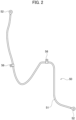
Fig. 2] FIG. 2 is a diagram showing a detailed structure of a first cord-like member. - [
Fig. 3] FIG. 3 is an explanatory diagram showing the configuration of a bracket. - [
Fig. 4] FIG. 4 is a cross-sectional view along line AA shown inFIG. 3 . - [
Fig. 5] FIG. 5 is an explanatory diagram showing a modified example of a bracket. - [
Fig. 6] FIG. 6 is an explanatory diagram showing a modified example of a bracket. - [
Fig. 7] FIG. 7 is an explanatory diagram showing a configuration of a vehicle back door according to a modified example. - [
Fig. 8] FIG. 8 is an explanatory diagram showing a configuration of a vehicle back door according to a modified example. - [
Fig. 9] FIG. 9 is a diagram showing a structure of a cord-like member according to a modified example. - An embodiment of the present invention will be described below with reference to the drawings. In the drawings, the same parts are denoted by the same reference numerals and the description thereof is omitted.
- A vehicle back door according to the present embodiment will be described. This vehicle back door is applied to a hatchback type automobile, and opens and closes an opening at the rear of a vehicle body. The upper end of the vehicle back door is connected to the rear end of the roof of the vehicle body via a hinge mechanism (not shown), and the vehicle back door is rotated in the vertical direction around the hinge mechanism.
- In
FIG. 1 , a vehicle back door is mainly configured of adoor body 1 formed of a resin panel member and first and second cord-like members door body 1. - The
door body 1 includes a doorinner panel 10 forming a door half body on the vehicle interior side and a doorouter panel 30 forming a door half body on the vehicle exterior side (seeFIG. 6 ). The doorinner panel 10 and the doorouter panel 30 are molded articles made of a resin material such as a glass fiber reinforced resin, and each of them is formed as one panel, for example. The peripheral part of the doorinner panel 10 and the peripheral part of the doorouter panel 30 are bonded together by using an adhesive, for example. Thedoor body 1 is formed into a closed cross section in which a space is formed.FIG. 1 shows thedoor body 1 as viewed from the rear of the vehicle.FIG. 1 shows only the doorinner panel 10 and does not show the doorouter panel 30. - Required shapes such as protrusions/recesses and openings necessary for the design and function of the vehicle back door are formed in the door
inner panel 10, but the doorinner panel 10 is formed in a flat shape as a whole. InFIG. 1 , detailed shapes such as protrusions/recesses and openings formed in the doorinner panel 10 are omitted (the same applies toFIGS. 7 and8 , which will be described later.). - An
opening 15 corresponding to the rear window is formed in the approximate center of the doorinner panel 10. The doorinner panel 10 includes anupper part 11 positioned above the opening 15,side parts opening 15, and alower part 14 positioned below the opening 15. - A plurality of
stiffening members inner panel 10 are formed on the doorinner panel 10. Each of thestiffening members - The first
stiffening members 20 are provided so as to span between theupper part 11 and theleft side part 12 and so as to span between theupper part 11 and theright side part 13. The first stiffeningmembers 20 reinforce mounting parts to which hinge mechanisms used for connecting thedoor body 1 to the roof rear end are mounted. The secondstiffening members 21 are provided so as to span between theleft side part 12 and thelower part 14 and so as to span between theright side part 13 and thelower part 14. The thirdstiffening member 22 is provided at the lower center portion of thelower part 14. The third stiffeningmember 22 reinforces a mounting part to which a latch unit of a lock mechanism for locking thedoor body 1 to a vehicle body is mounted. - The first and second cord-
like members members inner panel 10 once. The first and second cord-like members door body 1 when a large load has acted on thedoor body 1 such as in a rear collision. - The first cord-
like members 50 are provided on the right and left sides of the center of thedoor body 1. The right first cord-like members 50 and the left first cord-like members 50 are configured symmetrically with the center of thedoor body 1 as a boundary. Each of the first cord-like members 50 is routed from one of the firststiffening members 20, which is a first fixing point to the third stiffeningmember 22 which is a second fixing point, via one of the secondstiffening members 21 and a predetermined portion of thelower part 14 which are relay points. - The first cord-
like members 50 are routed to extend along a predetermined route instead of the shortest route in which the distance between routing points including the first and second fixing points and the two relay points is the shortest distance. From the viewpoint that the total length of the first cord-like members 50 is sufficiently longer than the total length of the shortest route and that interference between door components forming the vehicle back door and the first cord-like members 50 is avoided, the route along which the first cord-like members 50 are routed is preset. - As shown in
FIGS. 1 and2 , each first cord-like member 50 includes awire 51, mountingmembers 52, andbrackets 56. - The
wire 51 is a cord-like body part constituting each first cord-like member 50. Thewire 51 has sufficient strength such that thewire 51 is not easily broken even if thedoor body 1 is broken and a large tensile load acts on thewire 51. Thewire 51 is formed by twisting a plurality of metal core wires, for example. However, it is sufficient if thewire 51 has the strength described above, and thewire 51 may be formed by twisting carbon fibers. Further, thewire 51 may be formed of a belt-like member having a constant width. - The
mounting members 52 are provided at both ends of thewire 51. A mounting member 52 (hereinafter referred to as a "first mountingmember 52" when necessary) corresponding to one end of thewire 51 fixes one end of thewire 51 to thefirst stiffening member 20. A mounting member 52 (hereinafter referred to as a "second mountingmember 52" when necessary) corresponding to the other end of thewire 51 fixes the other end of thewire 51 to thethird stiffening member 20. - The mounting
members 52 are firmly fixed to the ends of thewire 51 such that the ends of thewire 51 are not detached easily. The mountingmembers 52 are crimp terminals and crimped to the ends of thewire 51, for example. Openings through whichfastening members 54 such as bolts are inserted are formed in the mountingmembers 52. The mountingmembers 52 are attached in a fixed state to thefirst stiffening member 20 and thethird stiffening member 22 by means of thefastening members 54. - One or
more brackets 56 are provided at an intermediate part positioned between the first mountingmember 52 and the second mountingmember 52 of thewire 51. Specifically, thebrackets 56 are provided between the central part of thewire 51 and the first mountingmember 52, and between the central part of thewire 51 and the second mountingmember 52. A bracket 56 (hereinafter, referred to as a "first bracket 56" when necessary) positioned nearer the first mountingmember 52 holds thewire 51 on thesecond stiffening member 20. A bracket 56 (hereinafter, referred to as a "second bracket 56" when necessary) positioned nearer the second mountingmember 52 holds thewire 51 in thelower part 14. - As shown in
FIGS. 3 and 4 , eachbracket 56 is formed by bending a flat plate, and includes anannular part 56c curved annularly and a pair of mountingpieces annular part 56c. - A space is formed in the
annular part 56c, and thewire 51 is inserted therein. The inner diameter of theannular part 56c is set to be larger than the outer diameter of thewire 51. Theannular part 56c annularly surrounds the outer periphery of thewire 51. Due to this configuration, thebracket 56 holds thewire 51 such that the wire is movable. - The pair of mounting
pieces annular part 56c to thedoor body 10, andopenings 56d through whichfastening members 58 such as bolts are inserted are formed in the pair of mountingpieces brackets 56 are attached in a fixed state on thesecond stiffening member 21 and in thelower part 14 by means of thefastening members 58. - As shown in
FIG. 1 , a second cord-like member 60 is provided in theupper part 11. The second cord-like member 60 is routed in the horizontal direction from the left first stiffeningmember 20 to the right first stiffeningmember 20. The second cord-like member 60 includes awire 61 and mountingmembers 62. - The configurations of the
wire 61 and the mountingmembers 62 correspond to the configurations of thewire 51 and the mountingmembers 52 of each first cord-like member 50. That is, a mountingmember 62 corresponding to one end of thewire 61 fixes one end of thewire 61 to the left first stiffeningmember 20. A mountingmember 62 corresponding to the other end of thewire 61 fixes the other end of thewire 61 to the right first stiffeningmember 20. The mountingmembers 62 are attached in a fixed state to the left and rightfirst stiffening members 20 by means offastening members 64. - The first cord-
like members 50 and the second cord-like member 60 are continuously routed to extend from thefirst stiffening member 20 at the upper left, to thesecond stiffening member 21 at the left center, to thethird stiffening member 22 at the lower center, to thesecond stiffening member 21 at the right center, to thefirst stiffening member 20 at the upper right, and then again to thefirst stiffening member 20 at the upper left. As a result, as in the case of theupper part 11, theleft side part 12, thelower part 14, and theright side part 13 which are located around theopening 15, the three cord-like members stiffening members - If a large load is input to the vehicle back door such as in a rear collision, there is a risk that the
door body 1 may be broken and shattered. However, the cord-like members door body 1. Therefore, pieces of thedoor body 1 divided due to the breakage can be connected to each other by means of the cord-like members door body 1. - Further, in accordance with the vehicle back door according to the present embodiment,
brackets 56 for holding thewire 51 with respect to thedoor body 1 are provided at an intermediate part of thewire 51 routed from thefirst stiffening member 20 to thethird stiffening member 22. Thebrackets 56 permit the movement of thewire 51. Since the mountingmembers 52 and thewire 51 are fixed, if the mountingmembers 52 are moved due to damage to thedoor body 1, thewire 51 is pulled. Even in such a situation, the intermediate part of thewire 51 can be moved with respect to thebrackets 56. Therefore, it is possible to suppress a large load from acting on thebrackets 56 attached to thedoor body 1. As a result, a concentration of stress at the mounting points (relay points) of thebrackets 56 in thedoor body 1 can be relieved. Accordingly, breakage of thedoor body 1 can be suppressed. - In contrast to the first cord-
like member 50 of the present embodiment, a configuration is considered in which a plurality of wires, for example, three wires that are first to third wires are continuously routed. That is, one end of the first wire is fixed to the first stiffening member 20 (the first fixing point), and the other end thereof is fixed to the second stiffening member 21 (the relay point). One end of the second wire is fixed to the second stiffening member 21 (the relay point), and the other end thereof is fixed to the lower part 14 (the relay point). Similarly, one end of the third wire is fixed to the lower part 14 (the relay point), and the other end thereof is fixed to the third stiffening member (the second fixing point). Even in such a configuration, the three wires are continuously routed to extend from thefirst stiffening member 20 to thethird stiffening member 22 via thesecond stiffening member 21 and thelower part 14, similar to the first cord-like member 50. - However, in the case of a configuration in which a plurality of wires of which both ends are fixed are connected, the wires are firmly fixed even at the relay points. Therefore, if the wires are pulled by being dragged by the fixing point, a large load acts on the relay points. As a result, stress is concentrated at the relay points of the
door body 1, and thedoor body 1 may be broken. In this regard, according to the first cord-like member 50 of the present embodiment, since thebrackets 56 are applied to the relay points of thedoor body 1 as described above, it is possible to relieve a concentration of stress at the relay points. Accordingly, breakage of thedoor body 1 can be suppressed. - Further, in order to prevent excessive tensile force from occurring in the wire, it is necessary to set a sufficient allowance to the length of the wire to be longer than the length of the shortest route between the routing points. In the case of a configuration in which a plurality of wires of which both ends are fixed are connected, it is necessary to set an allowance to each wire. Meanwhile, according to the configuration of the present embodiment, the movement of the
wire 51 is permitted by thebrackets 56 which hold the intermediate part of thewire 51. Therefore, if a surplus length (allowance) corresponding to a prescribed margin is set to the overall length of thewire 51, the surplus length corresponding to the margin can be utilized between each routing point by moving thewire 51. This can shorten the overall length of thewire 51 as compared with the case where a plurality of wires are routed. Therefore, weight increase and cost increase due to thewire 51 can be suppressed. - According to the first cord-
like member 50 of the present embodiment, both ends of thewire 51 are fixed, and the intermediate part of thewire 51 is held by thebrackets 56. Since both ends of thewire 51 are fixed, a situation occurs in which the end of thewire 51 is pulled due to the damage to thedoor body 1 or the like. Even if the end of thewire 51 is pulled, a large load is suppressed from acting on thebrackets 56 which hold the intermediate part of thewire 51. This can relieve a concentration of stress in thedoor body 1. Accordingly, breakage of thedoor body 1 can be suppressed. - In accordance with the vehicle back door according to the present embodiment, the
annular part 56c of thebracket 56 is configured to annularly surround the outer periphery of thewire 51. Therefore, the outer periphery of thewire 51 is not tightly clamped by thebracket 56, and a gap is secured between the outer periphery of thewire 51 and thebracket 56. Due to the presence of the gap, thebracket 56 can permit the movement of thewire 51. - Further, according to the vehicle back door of the present embodiment, a holding member for holding the
wire 51 in a movable manner is constituted by thebracket 56 attached to thedoor body 1. According to this configuration, thewire 51 can be easily held by attaching thebracket 56 to the door body. - Meanwhile, the
bracket 56 of the present embodiment annularly surrounds the outer periphery of thewire 51. Therefore, thewire 51 is held without coming off from thebracket 56 even if thewire 51 is pulled. However, thebracket 56 can permit the movement of thewire 51. Therefore, even when thewire 51 is pulled, thewire 51 can be released. Accordingly, thebracket 56 is not pulled together with thewire 51, and a large load can be suppressed from acting on thebracket 56. This can relieve a concentration of stress in thedoor body 1. Accordingly, breakage of thedoor body 1 can be suppressed. - In the above-described embodiment, the
bracket 56 formed by curving a flat plate is exemplified. However, the bracket may be configured to hold the outer periphery of thewire 51 while the gap is retained between thebracket 56 and the outer periphery of thewire 51. Thebracket 56 may include aring part 56e formed into a closed loop shape and a mountingpart 56f for mounting thering part 56e to thedoor body 1 as shown inFIG. 5 , for example. Thewire 51 can be movably held by thering part 56e by inserting thewire 51 into thering part 56e. - In the above-described embodiment, the
bracket 56 is attached to the doorinner panel 10. However, thewire 51 is routed in a space part between the doorinner panel 10 and the doorouter panel 30 which face each other. Therefore, as shown inFIG. 6 , abracket 35 provided on the doorouter panel 30 may movably hold thewire 51. Thebracket 35 shown inFIG. 6 has abracket body 36 attached on the doorouter panel 30 and a throughhole 37 formed in thebracket body 36. Thebracket 35 can movably hold thewire 51 by inserting thewire 51 into the throughhole 37. - Further, in the above-described embodiment, the
bracket 56 for holding the intermediate part of thewire 51 is applied to the first cord-like member 50, but the bracket is not applied to the second cord-like member 60. However, the bracket for holding the intermediate part of thewire 61 may be applied to the second cord-like member 60. - Further, in the above-described embodiment, the
brackets 56 are set at two positions of the intermediate part of thewire 51. However, it is sufficient if thebrackets 56 are provided such that thewire 51 spans locations where it is assumed that thedoor body 1 will break. The number of thebrackets 56 may be determined depending on the structure of thedoor body 1. -
FIG. 7 shows a doorinner panel 70 according to a modified example, for example. The doorinner panel 70 includes anupper part 71,side parts lower part 74.Wires 51 of the first cord-like members 50 are routed from stiffeningmembers 80 to a stiffeningmember 81 for reinforcing a latch unit, the stiffeningmembers 80 spanning from theside parts lower part 74. Abracket 56 is provided at one place of the intermediate part of thewire 51. The intermediate part of thewire 51 is movably held by thebracket 56. - In the above-described embodiment, the
bracket 56 is attached to thedoor body 1, and thewire 51 is movably held via thebracket 56. However, thewire 51 may be movably held by a door component constituting part of thedoor body 1 instead of another attachable/detachable component such as thebracket 56. -
FIG. 8 shows a doorinner panel 90 according to a modified example, for example. Awire 51 of the first cord-like member 50 is routed from a stiffeningmember 95 of theleft side part 92 to a stiffeningmember 95 of theright side part 93. The intermediate part of thewire 51 is inserted into throughholes member 100 for reinforcing a latch unit. The intermediate part of thewire 51 is movably held by the throughholes member 81. - According to this configuration, the stiffening
member 81 serving as a door component can be used as a holding member. Therefore, an increase in the number of components and cost can be suppressed. The movement of thewire 51 can be permitted by inserting thewire 51 into the throughholes member 81. - Further, according to the present embodiment, mounting
members 52 for holding thewire 51 in a fixed state are provided only at both ends of thewire 51. However, as shown inFIG. 9 , mountingmembers 52 for holding thewire 51 in a fixed state may be provided at one or more places of the intermediate part of thewire 51 by considering the total length of thewire 51. - Further, the mounting
members 52 may be provided not only at both ends of thewire 51 but also in the vicinity of both ends, and surplus portions including the ends of thewire 51 may be provided outside the mountingmembers 52. That is, it is sufficient if thewire 51 is routed at least from a first fixing point to a second fixing point. - In the present embodiment, the mounting
members 52 are provided at both ends of thewire 51. However, both ends of thewire 51 may be folded into a loop shape, thefastening members 54 may be inserted into both ends having the loop shape, and both ends of thewire 51 may be fixed to the first fixing point and the second fixing point. Further, both ends of thewire 51 may be firmly fastened to the first fixing point and the second fixing point. The mountingmembers 52 do not need to be composed of a member separate from thewire 51, and thewire 51 itself may function as a part of the mountingmembers 52. - As described above, although an embodiment of the present invention have been described, it should not be understood that the arguments and drawings forming part of this disclosure are intended to limit the present invention. Various alternative embodiments, examples, and operational techniques will be apparent to those skilled in the art from this disclosure.
-
- 1
-
Door body 1 - 10
- Door inner panel
- 20, 21, 22
- Stiffening members
- 30
- Door outer panel
- 50
- Cord-like member
- 51
- Wire
- 52
- Mounting member
- 56
- Bracket
- 70
- Door inner panel
- 80, 81
- Stiffening members
- 90
- Door inner panel
- 95, 100
- Stiffening members
Claims (5)
- A vehicle back door that opens and closes an opening at a rear of a vehicle body, the vehicle back door comprising:a door body formed of a resin panel member; anda cord-like member provided in the door body, whereinthe cord-like member includes:a cord-like body part that is routed from a first fixing point to a second fixing point of the door body,a first mounting member that is mounted to the first fixing point and fixes the cord-like body part to the first fixing point,a second mounting member that is mounted to the second fixing point and fixes the cord-like body part to the second fixing point, anda holding member that is provided in the door body and movably holds an intermediate part, between the first mounting member and the second mounting member, of the cord-like body part.
- The vehicle back door according to claim 1, whereinthe first mounting member is provided at one end of the cord-like body part and fixes the one end to the first fixing point, andthe second mounting member is provided at the other end of the cord-like body part and fixes the other end to the second fixing point.
- The vehicle back door according to claim 1 or 2, wherein
the holding member holds an outer periphery of the cord-like body part while a gap is retained between the holding member and the outer periphery of the cord-like body part. - The vehicle back door according to any one of claims 1 to 3, whereinthe holding member is a bracket that can be attached to and detached from the door body, andthe bracket includes an annular part that annularly surrounds the outer periphery of the cord-like body part, and a mounting piece that mounts the annular part to the door body.
- The vehicle back door according to any one of claims 1 to 3, whereinthe holding member is a door component constituting part of the door body, andthe door component includes a through hole through which the cord-like body part is inserted.
Applications Claiming Priority (1)
| Application Number | Priority Date | Filing Date | Title |
|---|---|---|---|
| PCT/JP2020/019941 WO2021234856A1 (en) | 2020-05-20 | 2020-05-20 | Vehicle back door |
Publications (2)
| Publication Number | Publication Date |
|---|---|
| EP4155102A1 true EP4155102A1 (en) | 2023-03-29 |
| EP4155102A4 EP4155102A4 (en) | 2023-07-12 |
Family
ID=78708297
Family Applications (1)
| Application Number | Title | Priority Date | Filing Date |
|---|---|---|---|
| EP20937078.2A Pending EP4155102A4 (en) | 2020-05-20 | 2020-05-20 | VEHICLE REAR DOOR |
Country Status (5)
| Country | Link |
|---|---|
| US (1) | US12296660B2 (en) |
| EP (1) | EP4155102A4 (en) |
| JP (1) | JP7529020B2 (en) |
| CN (1) | CN115666988B (en) |
| WO (1) | WO2021234856A1 (en) |
Families Citing this family (2)
| Publication number | Priority date | Publication date | Assignee | Title |
|---|---|---|---|---|
| CN117295626A (en) * | 2021-05-17 | 2023-12-26 | 八千代工业株式会社 | vehicle tailgate |
| JP2025038599A (en) * | 2023-09-07 | 2025-03-19 | 株式会社Subaru | Vehicle rear gate structure |
Family Cites Families (13)
| Publication number | Priority date | Publication date | Assignee | Title |
|---|---|---|---|---|
| JPS6166673A (en) | 1984-09-10 | 1986-04-05 | Toshiba Corp | Picture forming apparatus |
| JPS6166670A (en) | 1984-09-11 | 1986-04-05 | Matsushita Electric Ind Co Ltd | printing device |
| JPS6488186A (en) | 1987-09-30 | 1989-04-03 | Nippon Nuclear Fuel Dev | Structure for holding fuel element of nuclear fuel assembly |
| JP2010159037A (en) * | 2009-01-09 | 2010-07-22 | Kanto Auto Works Ltd | Back door of automobile |
| JP6190181B2 (en) | 2013-06-25 | 2017-08-30 | ダイキョーニシカワ株式会社 | Vehicle back door |
| JP6217332B2 (en) | 2013-11-13 | 2017-10-25 | スズキ株式会社 | Lower structure of resin back door |
| JP6166670B2 (en) | 2014-02-19 | 2017-07-19 | ダイキョーニシカワ株式会社 | Vehicle back door |
| JP6166673B2 (en) | 2014-02-27 | 2017-07-19 | ダイキョーニシカワ株式会社 | Vehicle back door |
| JP6488186B2 (en) | 2015-05-15 | 2019-03-20 | ダイキョーニシカワ株式会社 | Vehicle back door |
| JP6756548B2 (en) | 2016-08-31 | 2020-09-16 | ダイキョーニシカワ株式会社 | Vehicle backdoor |
| US11634013B2 (en) * | 2017-06-30 | 2023-04-25 | Magna Exteriors, Inc. | Liftgate reinforcement arrangements |
| JP6793356B2 (en) | 2018-01-31 | 2020-12-02 | 日本発條株式会社 | Manufacturing methods for wires, vehicle doors and wires |
| US11305822B2 (en) * | 2018-11-27 | 2022-04-19 | Magna Exteriors, Inc. | Liftgate arrangement having a carbon fiber reinforced sheet molding compound reinforcement |
-
2020
- 2020-05-20 US US17/926,458 patent/US12296660B2/en active Active
- 2020-05-20 CN CN202080101206.7A patent/CN115666988B/en active Active
- 2020-05-20 EP EP20937078.2A patent/EP4155102A4/en active Pending
- 2020-05-20 WO PCT/JP2020/019941 patent/WO2021234856A1/en not_active Ceased
- 2020-05-20 JP JP2022524758A patent/JP7529020B2/en active Active
Also Published As
| Publication number | Publication date |
|---|---|
| US20230182551A1 (en) | 2023-06-15 |
| CN115666988B (en) | 2025-07-29 |
| JP7529020B2 (en) | 2024-08-06 |
| EP4155102A4 (en) | 2023-07-12 |
| CN115666988A (en) | 2023-01-31 |
| US12296660B2 (en) | 2025-05-13 |
| JPWO2021234856A1 (en) | 2021-11-25 |
| WO2021234856A1 (en) | 2021-11-25 |
Similar Documents
| Publication | Publication Date | Title |
|---|---|---|
| US6571515B1 (en) | Motor vehicle door having a module carrier for mounting a window lift to the door | |
| US8419113B2 (en) | Structural member for vehicle | |
| CN106882273B (en) | tailgate structure | |
| US12296660B2 (en) | Vehicle back door | |
| CN107009859B (en) | tailgate structure | |
| EP2623399A1 (en) | Vehicle body structure | |
| US9649917B2 (en) | Vehicle resin back door structure | |
| CN113022711B (en) | Hat rack sheet metal assembly, assembling method thereof and vehicle | |
| US12606245B2 (en) | Vehicle rear structure | |
| JP2016022937A (en) | Side door structure for vehicles | |
| US12623725B2 (en) | Vehicle rear structure | |
| CN101992718A (en) | Assist grip mounting structure | |
| US10814757B2 (en) | Seatback frame for vehicles | |
| EP3950467B1 (en) | Composite elongated member | |
| JP2021154833A (en) | Vehicle backdoor structure | |
| EP3798034B1 (en) | Electrical component support structure | |
| CN114103605B (en) | Door structure of vehicle | |
| EP3147161B1 (en) | Seat back panel for vehicle | |
| JP4238389B2 (en) | Side step support structure | |
| EP4159492A1 (en) | Vehicle suspension structure | |
| KR100534938B1 (en) | Structure for mounting of seatback in rearseat for automobile | |
| JPH06270837A (en) | Reinforcement structure for vehicle members | |
| KR20020080970A (en) | Roof reinforcing assembly | |
| JP7463878B2 (en) | Side door structure | |
| EP4177138A1 (en) | Vehicle body rear structure |
Legal Events
| Date | Code | Title | Description |
|---|---|---|---|
| STAA | Information on the status of an ep patent application or granted ep patent |
Free format text: STATUS: THE INTERNATIONAL PUBLICATION HAS BEEN MADE |
|
| PUAI | Public reference made under article 153(3) epc to a published international application that has entered the european phase |
Free format text: ORIGINAL CODE: 0009012 |
|
| STAA | Information on the status of an ep patent application or granted ep patent |
Free format text: STATUS: REQUEST FOR EXAMINATION WAS MADE |
|
| 17P | Request for examination filed |
Effective date: 20221213 |
|
| AK | Designated contracting states |
Kind code of ref document: A1 Designated state(s): AL AT BE BG CH CY CZ DE DK EE ES FI FR GB GR HR HU IE IS IT LI LT LU LV MC MK MT NL NO PL PT RO RS SE SI SK SM TR |
|
| REG | Reference to a national code |
Ref country code: DE Ref legal event code: R079 Free format text: PREVIOUS MAIN CLASS: B60J0005000000 Ipc: B60J0005040000 |
|
| A4 | Supplementary search report drawn up and despatched |
Effective date: 20230612 |
|
| RIC1 | Information provided on ipc code assigned before grant |
Ipc: B60J 5/10 20060101ALI20230605BHEP Ipc: B60J 5/04 20060101AFI20230605BHEP |
|
| DAV | Request for validation of the european patent (deleted) | ||
| DAX | Request for extension of the european patent (deleted) | ||
| STAA | Information on the status of an ep patent application or granted ep patent |
Free format text: STATUS: EXAMINATION IS IN PROGRESS |
|
| 17Q | First examination report despatched |
Effective date: 20241219 |