EP4155044B1 - Anlage zur kontinuierlichen herstellung von zylindrischen schalen mit isolierenden eigenschaften und entsprechende zylindrische schalen - Google Patents
Anlage zur kontinuierlichen herstellung von zylindrischen schalen mit isolierenden eigenschaften und entsprechende zylindrische schalen Download PDFInfo
- Publication number
- EP4155044B1 EP4155044B1 EP22194847.4A EP22194847A EP4155044B1 EP 4155044 B1 EP4155044 B1 EP 4155044B1 EP 22194847 A EP22194847 A EP 22194847A EP 4155044 B1 EP4155044 B1 EP 4155044B1
- Authority
- EP
- European Patent Office
- Prior art keywords
- shells
- installation
- cylindrical
- moulds
- insulating properties
- Prior art date
- Legal status (The legal status is an assumption and is not a legal conclusion. Google has not performed a legal analysis and makes no representation as to the accuracy of the status listed.)
- Active
Links
Images


Classifications
-
- B—PERFORMING OPERATIONS; TRANSPORTING
- B29—WORKING OF PLASTICS; WORKING OF SUBSTANCES IN A PLASTIC STATE IN GENERAL
- B29C—SHAPING OR JOINING OF PLASTICS; SHAPING OF MATERIAL IN A PLASTIC STATE, NOT OTHERWISE PROVIDED FOR; AFTER-TREATMENT OF THE SHAPED PRODUCTS, e.g. REPAIRING
- B29C39/00—Shaping by casting, i.e. introducing the moulding material into a mould or between confining surfaces without significant moulding pressure; Apparatus therefor
- B29C39/02—Shaping by casting, i.e. introducing the moulding material into a mould or between confining surfaces without significant moulding pressure; Apparatus therefor for making articles of definite length, i.e. discrete articles
- B29C39/04—Shaping by casting, i.e. introducing the moulding material into a mould or between confining surfaces without significant moulding pressure; Apparatus therefor for making articles of definite length, i.e. discrete articles using movable moulds not applied
- B29C39/06—Shaping by casting, i.e. introducing the moulding material into a mould or between confining surfaces without significant moulding pressure; Apparatus therefor for making articles of definite length, i.e. discrete articles using movable moulds not applied continuously movable, e.g. along a production line
-
- B—PERFORMING OPERATIONS; TRANSPORTING
- B29—WORKING OF PLASTICS; WORKING OF SUBSTANCES IN A PLASTIC STATE IN GENERAL
- B29C—SHAPING OR JOINING OF PLASTICS; SHAPING OF MATERIAL IN A PLASTIC STATE, NOT OTHERWISE PROVIDED FOR; AFTER-TREATMENT OF THE SHAPED PRODUCTS, e.g. REPAIRING
- B29C33/00—Moulds or cores; Details thereof or accessories therefor
- B29C33/34—Moulds or cores; Details thereof or accessories therefor movable, e.g. to or from the moulding station
- B29C33/36—Moulds or cores; Details thereof or accessories therefor movable, e.g. to or from the moulding station continuously movable in one direction, e.g. in a closed circuit
-
- B—PERFORMING OPERATIONS; TRANSPORTING
- B29—WORKING OF PLASTICS; WORKING OF SUBSTANCES IN A PLASTIC STATE IN GENERAL
- B29C—SHAPING OR JOINING OF PLASTICS; SHAPING OF MATERIAL IN A PLASTIC STATE, NOT OTHERWISE PROVIDED FOR; AFTER-TREATMENT OF THE SHAPED PRODUCTS, e.g. REPAIRING
- B29C39/00—Shaping by casting, i.e. introducing the moulding material into a mould or between confining surfaces without significant moulding pressure; Apparatus therefor
- B29C39/22—Component parts, details or accessories; Auxiliary operations
- B29C39/26—Moulds or cores
-
- B—PERFORMING OPERATIONS; TRANSPORTING
- B29—WORKING OF PLASTICS; WORKING OF SUBSTANCES IN A PLASTIC STATE IN GENERAL
- B29K—INDEXING SCHEME ASSOCIATED WITH SUBCLASSES B29B, B29C OR B29D, RELATING TO MOULDING MATERIALS OR TO MATERIALS FOR MOULDS, REINFORCEMENTS, FILLERS OR PREFORMED PARTS, e.g. INSERTS
- B29K2075/00—Use of PU, i.e. polyureas or polyurethanes or derivatives thereof, as moulding material
-
- B—PERFORMING OPERATIONS; TRANSPORTING
- B29—WORKING OF PLASTICS; WORKING OF SUBSTANCES IN A PLASTIC STATE IN GENERAL
- B29K—INDEXING SCHEME ASSOCIATED WITH SUBCLASSES B29B, B29C OR B29D, RELATING TO MOULDING MATERIALS OR TO MATERIALS FOR MOULDS, REINFORCEMENTS, FILLERS OR PREFORMED PARTS, e.g. INSERTS
- B29K2105/00—Condition, form or state of moulded material or of the material to be shaped
- B29K2105/04—Condition, form or state of moulded material or of the material to be shaped cellular or porous
-
- B—PERFORMING OPERATIONS; TRANSPORTING
- B29—WORKING OF PLASTICS; WORKING OF SUBSTANCES IN A PLASTIC STATE IN GENERAL
- B29K—INDEXING SCHEME ASSOCIATED WITH SUBCLASSES B29B, B29C OR B29D, RELATING TO MOULDING MATERIALS OR TO MATERIALS FOR MOULDS, REINFORCEMENTS, FILLERS OR PREFORMED PARTS, e.g. INSERTS
- B29K2995/00—Properties of moulding materials, reinforcements, fillers, preformed parts or moulds
- B29K2995/0012—Properties of moulding materials, reinforcements, fillers, preformed parts or moulds having particular thermal properties
- B29K2995/0015—Insulating
-
- B—PERFORMING OPERATIONS; TRANSPORTING
- B29—WORKING OF PLASTICS; WORKING OF SUBSTANCES IN A PLASTIC STATE IN GENERAL
- B29L—INDEXING SCHEME ASSOCIATED WITH SUBCLASS B29C, RELATING TO PARTICULAR ARTICLES
- B29L2023/00—Tubular articles
- B29L2023/22—Tubes or pipes, i.e. rigid
- B29L2023/225—Insulated
Definitions
- the invention belongs to the general field of construction and industry, more specifically, to the field of thermal insulation of pipes or conduits with circular cross-section. It aims in particular at an installation more particularly dedicated to the production of cylindrical shells or half-shells with insulating and thermal properties.
- the invention also relates to such shells or half-shells provided with insulating and thermal properties.
- the objective sought by the present invention is to propose an installation making it possible to drastically limit these falls to reduce their production to almost zero.
- the invention also relates to shells or half-shells with insulating and thermal properties, immediately usable by operators, that is to say without requiring the addition of any additional element.
- the invention consists in proposing an installation allowing directly the conformation of shells or half-shells with thermal insulating properties according to the desired dimensions, due to the reaction of the constituents respectively of the polyurethane or polyisocyanurate "in situ", without requiring any subsequent cutting, other than that of the desired length of said shells or half-shells.
- the length of said conveyors, respectively upper and lower, and their speed of progression are such that there is the necessary time, once the injection of the respective constituents has been carried out, to allow their interaction with each other (in compliance with the desired densities) with a view to the expansion of the foam thus produced on the one hand, then the solidification of said foam on the other hand, so as to obtain at the end of progression, at the so-called reception station, the desired product with a view to final use.
- Said product is therefore in the form of shells or half-shells, continuously emerging from the installation, and which should be automatically cut into sections to the length corresponding to that desired, or according to standard lengths. These shells or half-shells then obtained, are directly usable, and can simply be assembled around the pipe to be protected.
- the conveyors are each made up of two tracks, respectively an upper track and a lower track, typically each made up of two parallel rails, on which the male and female molds respectively are capable of progressing, the latter being provided for this purpose with rollers mounted free to rotate.
- the molds are driven on the rails by means of the thrust of a jack in the forward direction, that is to say in the direction of progression of the molds towards a zone or station for receiving the shells or half-shells, and of a chain or a belt for their return to the initial position.
- the rails of the respective ends of the two tracks, along a length at least equal to that of the molds are movable in vertical translation under the action of a jack, so as to allow the molds to change tracks.
- the installation also comprises, upstream of the filling station, a device for positioning, at the bottom of the female molds, a coating with a vapor barrier function, for example based on aluminum.
- the installation also includes, upstream of the filling station, a device for positioning a non-stick coating in contact with the cylindrical protruding part of the male mold.
- the male molds comprise a removable imprint, reversibly secured to a support itself received on the rails of the upper conveyor.
- At least the projecting parts of the imprint, in the form of a half-cylinder, are advantageously coated with a silicone film, or even polytetrafluoroethylene (better known under the registered trademark Teflon ® ), in order to facilitate the demolding operation.
- the invention also relates to shells or half-shells with thermal insulating properties.
- These shells or half-shells consist of a main part in the form of a straight cylindrical sleeve, i.e. corresponding to the volume between the side walls of two concentric cylinders of the same height, made of a polyurethane or polyisocyanurate foam, the external face of which is coated with a vapor barrier, and therefore the internal face is coated with an anti-corrosive film.
- the vapor barrier is typically made of a complex, one of the constituents of which is an aluminum film. More precisely, this vapor barrier can be made of a sandwich made of a film made of glass fibers, coated on both sides with an aluminum film.
- the anti-corrosive film can be made of plastic film or paper sheet.
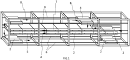
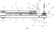
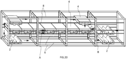
- THE figures 1 And 2 represents a schematic view of the installation of the invention, according to a first embodiment.
- it is fundamentally constituted by two conveyors, respectively a lower conveyor (1) receiving imprints (2) of female molds, and an upper conveyor (3) receiving imprints of male molds (4).
- these conveyors are each made up of two pairs of parallel rails, respectively (5, 6) and (7, 8), on which the molds are capable of moving, the latter being for this purpose equipped with rollers (9) mounted to rotate freely, as can be better seen in the Figures 3 to 5 Or 8 and 9
- the effective movement of the molds along the rails (5, 7) is ensured according to arrow A by the thrust of a jack (not shown) resting on the female mold (2) located furthest to the right on the figure 2 .
- the rails respectively lower (7) of the upper conveyor (3) and upper (5) of the lower conveyor (1), parallel to each other, are intended to allow the progression of the molds, respectively male (4) and female (2) according to arrow A, that is to say heading left on the figures 1 And 2 .
- the upper rails (8) of the upper conveyor (3) and the lower rails (6) of the lower conveyor (1) are intended to allow the repatriation of the molds according to the arrows B in said figures, in the direction respectively of the filling station (10) for the male molds (4) and of the upstream station (14) for the female molds, that is to say located upstream of the filling station (10), the notions of upstream and downstream having to be interpreted in relation to the direction of progression of the molds symbolized by the arrow A.
- the male and female molds cooperate with each other, and more precisely are in partial contact with each other in order to define between them a volume (15) of appropriate dimensions, depending on the dimensions of the half-shells that one wishes to produce.
- This volume (15) is intended to receive the constituents of a polyurethane or a polyisocyanurate at the filling station (10), said constituents, and for example a polyol and an isocyanate being introduced from a mixing head (16) by means of a tube (17) introduced into said volume (15).
- said tube (17) is relatively deeply introduced into said volume (15) until it approaches the downstream end of said volume in the vicinity of the junction between two consecutive molds, so as to ensure correct filling of the latter with a polyol and isocyanate mixture, and consequently, sufficient expansion of the product resulting from this mixture to fill the entirety of said volume.
- the male and female molds undergo a vertical ascent and descent respectively in order, on the one hand, to allow the release of the half-shells then exiting the installation in continuous mode, and which can then be cut to the desired length by any suitable means such as a saw, according to the standard dimensions requested by the market and for the operator to recover the half-shells (if two-cavity molds), and on the other hand, position said molds at the level of the rails (6, 8) returning to the upstream level of the installation, and thus restart a cycle.
- the male molds stop their return vertically above the filling station (10).
- the female molds continue their return to an upstream station (14), itself advantageously made up of two sub-stations, respectively (12) for positioning a film or complex with a vapor barrier function, typically based on aluminum at the bottom of the female impressions, and (11) at which the introduction of the tube (17) of the constituents of the polyurethane or polyisocyanurate foam begins.
- the relative vertical movement of the male and female molds at the two ends of the conveyors is ensured by means of jacks (18), pneumatic in the example described, but which could operate electrically or hydraulically, illustrated in the Figures 3 to 5 And 10 .
- the rails (5 - 8) are in fact made up of rail sections (19), independent of said rails (5 - 8) in order to allow the movement of both male and female molds at said stations in an upward or downward movement.
- the rod (21) of the jacks (18) is integral with a support (22) of said rail sections, said support (22) being capable of sliding vertically along a guide rod (20).
- the receiving rails of the rollers (9) of the molds in question are shaped to allow effective guidance of said rollers.
- the sectional view of said rail (19) on the figure 10 illustrates the shape of the rails, at least on one side of the conveyors, the other side can simply be made of an angle iron, for example metallic.
- FIG. 3 illustrates a female mold (2) and a male mold (4) positioned either at the receiving station or at the filling station. They are therefore, at this level, spaced apart from each other.
- FIG 4 illustrates the vertical rise of the female mold (2) at the level of the upper rail (5) of the lower conveyor (1).
- the figure 5 illustrates the lowering or vertical descent of the male mold (4) at the level of the lower rail (7) of the upper conveyor (3), so as to define the semi-cylindrical volume (15) mentioned above.
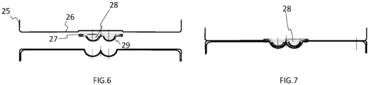
- the male mold consists of a support (25), provided with rollers (not shown in the Figures 6 and 7 ), and defining a grip or clearance (26) intended to receive a removable imprint (27).
- the imprint can be fixed to the support, for example, by means of centering pins (not shown) extending from the grip (26) and cooperating with corresponding orifices provided on the imprint (27). Then the effective securing can be achieved by means of wing screws.
- the core (28) of the imprint (27) is made of a hard and rigid material, such as wood.
- This core is coated with a layer of silicone (29) or polytetrafluoroethylene, and generally, any material with a very low coefficient of friction capable of resisting the temperature rise resulting from the formation of the foam.
- the shell or half-shell can be cut, for example automatically into sections according to the standard dimensions required by the market, then demolded.
- the installation advantageously comprises recovery rollers (30), mounted on a support (31), the latter being actuable according to a vertical movement by means of one or more jacks (32).
- These recovery rollers (30), mounted freely in rotation, are aligned in direction A, and bear on the upper face (33) of the male molds substantially in a central position relative to the lateral edges of said molds.
- An equivalent system can be set up symmetrically in contact with the female molds, and therefore in contact with their lower surface, if the pressure generated by the reaction between the constituents of the polyurethane or polyisocyanurate foam is too high.
- a vapor barrier complex or film (35) is advantageously positioned at the bottom of the female molds (2) before injection of the foam constituents into the volume (15), and therefore typically at the level of the station (12).
- This complex is for example a sandwich structure trapping between two aluminum films, with a typical thickness of around 12 micrometers, a layer based on a glass and aluminum grid, polyethylene, with a typical thickness of around 23 micrometers.
- the vapor barrier film or complex (35), stored in the form of a reel (36), is unrolled, then brought vertically above said female mold at the station (12).
- a device (37), illustrated in more detail in the Figures 14 and 15 is then actuated, in order to block said film (35) along the lateral edge of said female mold (2).
- This device (37) is for example made up of a series of rollers (38) mounted freely in rotation on a support (39) and along the same horizontal line, said support being capable of being animated by a vertical movement of ascent and descent by means of a jack (54).
- this device consists of two volume elements (41) and (42), of circular cross-section, the external diameter of which corresponds substantially to the internal diameter of the female imprints of said mold (2).
- These volume elements (41, 42) undergo one after the other a downward vertical movement, so as to press the vapor barrier film (35) against the internal wall of the female imprints, by means of a jack (44), the rod of which is integral with a support (43) of said volume elements (41, 42).
- the volume element (41) closest to the side edge at which the film (35) is blocked by the blocking device (37) descends first (left part of the figure 12 ). Then the second volume element (42) descends in turn, said first element (41) remaining in the low position, in order to ensure the correct application of the film (35) against the entire internal wall of the female imprint.
- the vapor barrier complex (35) due to its nature, retains the shape given to it at the station (12) and is pressed against the bottom of said female mold during the process due to the pressure exerted by the expansion of the foam (polyurethane or polyisocyanurate).
- the progression of the molds (direction A) within the installation causes the traction of said vapor barrier complex (35) of the coil (36).
- Said foam in the process of expansion adheres to the vapor barrier complex (35). In doing so, adhering to the half-shells, in particular at the receiving station (13), it is cut simultaneously with the latter.
- a film made of an anti-corrosive material for example a plastic film or paper, for example with a thickness of around 30 micrometers.
- a film or paper (45) is unwound from a reel (46) substantially when the male and female molds are positioned at the filling station (10).
- this film (45) is put in place manually at the sub-station (11).
- the foam when expanding, adheres to this anti-corrosive film (45), and at the level of the reception station (13), said film is found at the level of the internal half-cylinder of the half-shells.
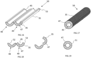
- These half-shells are therefore made up of a central core (47) made of polyurethane or polyisocyanurate foam, coated on the outside with a vapor barrier complex (35), and having an anti-corrosive film (45) on the inside.
- a central core 47) made of polyurethane or polyisocyanurate foam, coated on the outside with a vapor barrier complex (35), and having an anti-corrosive film (45) on the inside.
- the thickness of the central core is standardized, and can have the following values: 30, 40 or 50 millimeters, according to standard requests.
- two half-shells (48, 49) are obtained, secured to each other by the vapor barrier complex (35).
- the vapor barrier complex (35) By closing the half-shells on each other, for example around the pipe or the pipeline to be protected, and by securing the free edge of said half-shells not secured to each other by the vapor barrier complex (35), for example by means of an adhesive film (51), the resulting shell is then effectively positioned, allowing the latter to perform the thermal insulating function assigned to it.
- This positioning can also be optimized by making opposing and complementary cutouts (52) and (53) provided on said free edges, intended to cooperate with each other, said cutouts being able to result from molding within the installation described above.
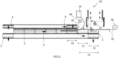
- the mold imprints are oriented according to the direction of progression A of said molds.
- the imprints of the female molds (2) are oriented perpendicularly to said direction of progression.
- the orientation of the male molds (4) is also perpendicular to this direction of progression A.
- the general operating principle remains identical to that previously described in connection with the Figures 1 to 12 .
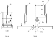
- a device (59) similar to the device (40) of the first embodiment, and illustrated in more detail in the Figures 25 and 26 comprises two volume elements, in this case (60) and (61), providing the same function as the elements (41, 42) mentioned above.
- These elements (60, 61) are also oriented perpendicularly to the direction of progression of the molds, in order to be able to cooperate with the female imprints. They are lowered one after the other by means of a jack (62), after blocking the film (35) upstream, then lowering the element (60), then the element (61).
- lateral cheeks (65) are put in place on either side of the female imprint, and in particular fixed at this level by means of brackets or any equivalent system, in order to thus define the volume (15) during the lowering of the male imprint.
- the face of the cheeks intended to come into contact with the polyurethane or polyisocyanurate foam is advantageously coated with silicone or a low-adhesive material, in order to facilitate demolding at the end of the progression of the molds in the installation.
- the mold (2) then undergoes an ascension (see first embodiment), and free rotating rollers (66) then come to bear against the cheeks (65) using a jack (67) with horizontal movement ( figure 23 ), in order to ensure the recovery of the pressure generated by the expansion of the foam.
- the female mold advances along direction A to station (10), at which the male mold (4) is lowered, in order to cooperate with the female mold (2) and thus define the volume (15).
- the injection of the polyurethane or polyisocyanurate constituents can then be carried out, and the process follows its course, as described with the first embodiment of the invention.
- the injection of said constituents can be carried out using a single nozzle, traveling linearly and in a direction perpendicular to direction A along the upstream imprint and filling it, and following the progression in discrete mode of the female mold, returning in the opposite direction to fill the downstream imprint.
- the operation of the installation of the invention is such that, in addition to the advanced automation of the production of shells or half-shells, the production rate is significantly high, since it is also possible to produce such a shell or half-shell every 20 seconds.
Landscapes
- Engineering & Computer Science (AREA)
- Mechanical Engineering (AREA)
- Casting Or Compression Moulding Of Plastics Or The Like (AREA)
Claims (11)
- Anlage zur kontinuierlichen Herstellung von zylindrischen Schalen oder Halbschalen (50) mit wärmeisolierenden Eigenschaften, umfassend:• ein lineares Doppelförderband mit diskreter Förderung in die gleiche Richtung und mit gleicher Geschwindigkeit:▪ ein unteres Förderband (1), das eine Vielzahl von abnehmbaren Matrizenformen (2) aufnimmt;▪ ein oberes Förderband (3), das sich direkt über dem unteren Förderband (1) befindet und eine identische Anzahl von abnehmbaren Patrizenformen (4) aufnimmt;wobei die Matrizen- und Patrizenformen so geformt sind, dass sie in Arbeitsstellung zueinander ein halbzylindrisches Volumen (15) definieren;wobei der Doppelförderer in der Lage ist, die Formen zwischen einer Station (10) zum Füllen des Volumens (15) mit Elementen, die geeignet sind, das Material mit wärmeisolierenden Eigenschaften der Schalen oder Halbschalen zu bilden, und einer Station (13) zum Empfang und zur Entnahme der Schalen oder Halbschalen zu bewegen;• mindestens ein Rohr (17) oder eine Düse zum Einbringen von Bestandteilen, die miteinander interagieren können, um ein Polyurethan oder ein Polyisocyanurat zu bilden, in das so definierte Volumen (15) an der Füllstation (10).
- Anlage zur kontinuierlichen Herstellung von zylindrischen Halbschalen oder Schalen mit wärmeisolierenden Eigenschaften nach Anspruch 1, dadurch gekennzeichnet, dass der untere (1) und der obere (3) Förderer jeweils aus zwei Bahnen bestehen, jeweils einer oberen und einer unteren Bahn, auf denen die Patrizen- bzw. Matrizenformen fortbewegt werden können, wobei die Formen auf den Bahnen insbesondere mittels eines Stellglieds in Richtung der Fortbewegung der Formen zwischen der Füllstation (10) und einer Empfangsstation (13) der Schalen oder Halbschalen und mittels einer Kette oder eines Riemens in umgekehrter Richtung angetrieben werden.
- Anlage zur kontinuierlichen Herstellung von zylindrischen Schalen oder Halbschalen mit wärmeisolierenden Eigenschaften nach Anspruch 2, dadurch gekennzeichnet, dass die beiden Enden der beiden jeweiligen Bahnen, deren Länge mindestens gleich der der Formen ist, unter der Wirkung eines Stellglieds (18) in vertikaler Translation beweglich sind, so dass die Formen die Bahnen wechseln können.
- Anlage zur kontinuierlichen Herstellung von zylindrischen Schalen oder Halbschalen mit wärmeisolierenden Eigenschaften nach einem der Ansprüche 2 und 3, dadurch gekennzeichnet, dass die jeweils oberen und unteren Bahnen aus zueinander parallelen Schienen (5 - 8) bestehen, auf denen die Formen fortbewegt werden, wobei letztere zu diesem Zweck mit frei drehbaren Laufrollen (9) versehen sind.
- Anlage zur kontinuierlichen Herstellung von zylindrischen Schalen oder Halbschalen mit wärmeisolierenden Eigenschaften nach einem der Ansprüche 1 bis 4, dadurch gekennzeichnet, dass sie außerdem vor der Füllstation (10) eine Positionierungsvorrichtung (37, 40) am Boden der Matrizenformen für eine Folie oder einen Verbundstoff mit Dampfsperrfunktion (35) umfasst.
- Anlage zur kontinuierlichen Herstellung von zylindrischen Schalen oder Halbschalen mit wärmeisolierenden Eigenschaften nach einem der Ansprüche 1 bis 5, dadurch gekennzeichnet, dass sie ebenfalls vor der Füllstation (10) eine Positionierungsvorrichtung für eine Korrosionsschutzfolie (45) in Kontakt mit dem zylindrischen Vorsprung der Patrizenform umfasst, wobei diese Korrosionsschutzfolie (45) aus einem dehnbaren Kunststoffmaterial oder einer Papierfolie besteht.
- Anlage zur kontinuierlichen Herstellung von zylindrischen Schalen oder Halbschalen mit wärmeisolierenden Eigenschaften nach einem der Ansprüche 1 bis 6, dadurch gekennzeichnet, dass sie Aufnahmerollen (30) umfasst, die auf einem Träger (31) montiert sind, der gemäß einer vertikalen Bewegung mittels eines oder mehrerer Stellglieder (32) betätigt werden kann, und die dazu bestimmt sind, sich auf der Oberseite (33) der Patrizenformen im Wesentlichen in einer mittigen Position in Bezug auf die seitlichen Ränder der Formen abzustützen.
- Anlage zur kontinuierlichen Herstellung von zylindrischen Schalen oder Halbschalen mit wärmeisolierenden Eigenschaften nach einem der Ansprüche 1 bis 7, dadurch gekennzeichnet, dass die Abdrücke der Matrizenformen (2) und der Patrizenformen (4) senkrecht zur Richtung A ihrer Fortbewegung innerhalb der genannten Anlage ausgerichtet sind.
- Schalen oder Halbschalen (50) mit wärmeisolierenden Eigenschaften, mit zylindrischem oder halbzylindrischem Querschnitt, die mithilfe der Anlage nach einem der Ansprüche 1 bis 8 erhalten werden, dadurch gekennzeichnet, dass sie aus einem Hauptteil (47) in Form einer geraden zylindrischen Hülse bestehen, das heißt, die dem Volumen zwischen den Seitenwänden von zwei konzentrischen Zylindern gleicher Höhe entspricht, wobei der Hauptteil aus einem Polyurethan- oder Polyisocyanurat-Schaumstoff hergestellt ist, dessen Außenseite mit einer Folie oder einem Verbundstoff mit Dampfsperrfunktion (35) beschichtet ist und daher die Innenseite mit einer Korrosionsschutzfolie (45) beschichtet ist.
- Schalen oder Halbschalen mit wärmeisolierenden Eigenschaften nach Anspruch 9, dadurch gekennzeichnet, dass die Folie oder der Verbundstoff mit Dampfsperrfunktion (35) aus einer Aluminiumfolie hergestellt ist.
- Schalen oder Halbschalen mit wärmeisolierenden Eigenschaften nach einem der Ansprüche 9 und 10, dadurch gekennzeichnet, dass die Korrosionsschutzfolie (45) aus einer Kunststofffolie oder einem Papierbogen besteht.
Applications Claiming Priority (1)
| Application Number | Priority Date | Filing Date | Title |
|---|---|---|---|
| FR2110159A FR3127429B1 (fr) | 2021-09-27 | 2021-09-27 | Installation pour la realisation en continu de coquilles cylindriques a proprietes isolantes et coquilles cylindriques associees |
Publications (2)
| Publication Number | Publication Date |
|---|---|
| EP4155044A1 EP4155044A1 (de) | 2023-03-29 |
| EP4155044B1 true EP4155044B1 (de) | 2024-11-20 |
Family
ID=78536379
Family Applications (1)
| Application Number | Title | Priority Date | Filing Date |
|---|---|---|---|
| EP22194847.4A Active EP4155044B1 (de) | 2021-09-27 | 2022-09-09 | Anlage zur kontinuierlichen herstellung von zylindrischen schalen mit isolierenden eigenschaften und entsprechende zylindrische schalen |
Country Status (4)
| Country | Link |
|---|---|
| EP (1) | EP4155044B1 (de) |
| ES (1) | ES3018910T3 (de) |
| FR (1) | FR3127429B1 (de) |
| PL (1) | PL4155044T3 (de) |
Family Cites Families (4)
| Publication number | Priority date | Publication date | Assignee | Title |
|---|---|---|---|---|
| US3147165A (en) * | 1959-12-07 | 1964-09-01 | Owens Corning Fiberglass Corp | Method of manufacturing pipe insulation |
| JP2006123374A (ja) * | 2004-10-29 | 2006-05-18 | Makoto Nishizawa | 射出成形機などの断熱カバー |
| KR101905943B1 (ko) * | 2013-02-28 | 2018-10-08 | 니찌아스 카부시키카이샤 | 불소수지의 접합부를 포함하는 물품 및 그의 제조방법 |
| EP3112115B1 (de) * | 2015-06-26 | 2018-08-15 | Cannon S.p.A. | Verfahren und vorrichtung zum fördern und aufschäumen von objekten |
-
2021
- 2021-09-27 FR FR2110159A patent/FR3127429B1/fr active Active
-
2022
- 2022-09-09 ES ES22194847T patent/ES3018910T3/es active Active
- 2022-09-09 EP EP22194847.4A patent/EP4155044B1/de active Active
- 2022-09-09 PL PL22194847.4T patent/PL4155044T3/pl unknown
Also Published As
| Publication number | Publication date |
|---|---|
| FR3127429A1 (fr) | 2023-03-31 |
| PL4155044T4 (pl) | 2025-04-22 |
| PL4155044T3 (pl) | 2025-04-22 |
| FR3127429B1 (fr) | 2023-09-01 |
| ES3018910T3 (en) | 2025-05-19 |
| EP4155044A1 (de) | 2023-03-29 |
Similar Documents
| Publication | Publication Date | Title |
|---|---|---|
| EP2125345B1 (de) | Verfahren und vorrichtung zur herstellung von teilen aus einem verbundwerkstoff, insbesondere abschnitte eines flugzeugrumpfes | |
| EP0171309B1 (de) | Vorbereitung eines Kunststoffes zum Extrudieren, insbesondere in Form eines kalibrierten Bandes zur Verwendung als Verbindungsmaterial und als Zwischeneinlage in Mehrfachverglasungen | |
| EP0638408A1 (de) | Verfahren und Vorrichtung zur Herstellung einer mit einem angeformten Rahmen aus einem thermoplastischen Polymer versehene Glasscheibe | |
| WO2011098734A1 (fr) | Decoupe de preformes avant injection rtm par jet d'eau et cryogenisation | |
| EP0469976B1 (de) | Verfahren und automatische Vorrichtung zur Herstellung kalibrierter Ringe aus profiliertem oder unprofiliertem Extrudat | |
| EP0061412B1 (de) | Verfahren und Vorrichtung zur Herstellung von Kunststoffschaumbahnen | |
| WO2008096290A2 (fr) | Méthode de réalisation d'un objet multicouche | |
| EP1066148B1 (de) | Verfahren zum herstellen eines kraftfahrzeug-bauteils durch einspritzen von kunststoffmaterial, verfahren zum sequenziellen einspritzen von kunststoffmaterial, form zur durchführung des verfahrens, und so hergestelltes bauteil | |
| FR2833203A1 (fr) | Procede de fabrication par centrifugation de viroles a double paroi | |
| EP4155044B1 (de) | Anlage zur kontinuierlichen herstellung von zylindrischen schalen mit isolierenden eigenschaften und entsprechende zylindrische schalen | |
| EP0270462B1 (de) | Verfahren und Anordnung zur Herstellung eines Verbundkörpers mit konstantem Querschnitt zusammengesetzt aus einem Kern und einer äusseren Hülle und damit erhaltener Verbundkörper | |
| EP2222450B1 (de) | Vorrichtung und Verfahren zur Herstellung einer Lauffläche | |
| EP1066142B1 (de) | Einrichtung zur herstellung von latexgegenständen, wie beispielweise kissen | |
| EP1997977B1 (de) | Fertigwandplatte zur Wandverkleidung von Gebäuden | |
| CH430162A (fr) | Procédé pour la fabrication en continu de corps creux moulés à partir d'une feuille de matière plastique, installation pour la mise en oeuvre de ce procédé et corps creux obtenu par ledit procédé | |
| FR3066720B1 (fr) | Module de decoupe pour une tete de placement d'un ruban de fibres impregnees, tete de placement et dispositif de placement d'un tel ruban de fibres | |
| EP0006820B1 (de) | Verfahren zur Herstellung von Formteilen aus Holzteilchen, Vorrichtung zur Durchführung dieses Verfahrens und die hergestellten Formteile | |
| CA1029908A (en) | Installation for the continuous manufacture of synthetic material panels | |
| FR3097157A1 (fr) | Module de dépose pour tête de dépose de tronçons de bande de fibres pour la réalisation de pièce en matériaux composites, tête de dépose, robot de dépose, et procédé de dépose. | |
| FR3097159A1 (fr) | Module de découpe pour tête de dépose de tronçons de bande de fibres pour la réalisation de pièce en matériaux composites, tête de dépose, robot de dépose et procédé de découpe et procédé de dépose. | |
| FR2497720A1 (fr) | Procede et installation pour la fabrication de panneaux en mousse expansee | |
| FR2580218A1 (fr) | Procede et machine pour le moulage par compression a chaud de pieces d'aspect pourvues d'un revetement sur une face | |
| WO2018109327A1 (fr) | Machine et procede de moulage de preformes par injection compression | |
| FR3097156A1 (fr) | Module d’alimentation pour tête de dépose de tronçons de bande de fibres pour la réalisation de pièce en matériaux composites, tête de dépose, robot de dépose et procédé d’alimentation et procédé de dépose. | |
| MC412A1 (fr) | Procédé de fabrication de panneaux et d'élements en matiere expansée et machine pour la mise en oeuvre dudit procédé |
Legal Events
| Date | Code | Title | Description |
|---|---|---|---|
| PUAI | Public reference made under article 153(3) epc to a published international application that has entered the european phase |
Free format text: ORIGINAL CODE: 0009012 |
|
| STAA | Information on the status of an ep patent application or granted ep patent |
Free format text: STATUS: THE APPLICATION HAS BEEN PUBLISHED |
|
| AK | Designated contracting states |
Kind code of ref document: A1 Designated state(s): AL AT BE BG CH CY CZ DE DK EE ES FI FR GB GR HR HU IE IS IT LI LT LU LV MC MK MT NL NO PL PT RO RS SE SI SK SM TR |
|
| STAA | Information on the status of an ep patent application or granted ep patent |
Free format text: STATUS: REQUEST FOR EXAMINATION WAS MADE |
|
| P01 | Opt-out of the competence of the unified patent court (upc) registered |
Effective date: 20230527 |
|
| 17P | Request for examination filed |
Effective date: 20230613 |
|
| RBV | Designated contracting states (corrected) |
Designated state(s): AL AT BE BG CH CY CZ DE DK EE ES FI FR GB GR HR HU IE IS IT LI LT LU LV MC MK MT NL NO PL PT RO RS SE SI SK SM TR |
|
| GRAP | Despatch of communication of intention to grant a patent |
Free format text: ORIGINAL CODE: EPIDOSNIGR1 |
|
| STAA | Information on the status of an ep patent application or granted ep patent |
Free format text: STATUS: GRANT OF PATENT IS INTENDED |
|
| GRAS | Grant fee paid |
Free format text: ORIGINAL CODE: EPIDOSNIGR3 |
|
| INTG | Intention to grant announced |
Effective date: 20240912 |
|
| GRAA | (expected) grant |
Free format text: ORIGINAL CODE: 0009210 |
|
| STAA | Information on the status of an ep patent application or granted ep patent |
Free format text: STATUS: THE PATENT HAS BEEN GRANTED |
|
| RAP1 | Party data changed (applicant data changed or rights of an application transferred) |
Owner name: BULBAT |
|
| AK | Designated contracting states |
Kind code of ref document: B1 Designated state(s): AL AT BE BG CH CY CZ DE DK EE ES FI FR GB GR HR HU IE IS IT LI LT LU LV MC MK MT NL NO PL PT RO RS SE SI SK SM TR |
|
| REG | Reference to a national code |
Ref country code: GB Ref legal event code: FG4D Free format text: NOT ENGLISH |
|
| REG | Reference to a national code |
Ref country code: CH Ref legal event code: EP |
|
| REG | Reference to a national code |
Ref country code: DE Ref legal event code: R096 Ref document number: 602022007878 Country of ref document: DE |
|
| REG | Reference to a national code |
Ref country code: IE Ref legal event code: FG4D Free format text: LANGUAGE OF EP DOCUMENT: FRENCH |
|
| REG | Reference to a national code |
Ref country code: NL Ref legal event code: FP |
|
| REG | Reference to a national code |
Ref country code: SE Ref legal event code: TRGR |
|
| REG | Reference to a national code |
Ref country code: LT Ref legal event code: MG9D |
|
| PG25 | Lapsed in a contracting state [announced via postgrant information from national office to epo] |
Ref country code: HR Free format text: LAPSE BECAUSE OF FAILURE TO SUBMIT A TRANSLATION OF THE DESCRIPTION OR TO PAY THE FEE WITHIN THE PRESCRIBED TIME-LIMIT Effective date: 20241120 Ref country code: IS Free format text: LAPSE BECAUSE OF FAILURE TO SUBMIT A TRANSLATION OF THE DESCRIPTION OR TO PAY THE FEE WITHIN THE PRESCRIBED TIME-LIMIT Effective date: 20250320 Ref country code: PT Free format text: LAPSE BECAUSE OF FAILURE TO SUBMIT A TRANSLATION OF THE DESCRIPTION OR TO PAY THE FEE WITHIN THE PRESCRIBED TIME-LIMIT Effective date: 20250320 |
|
| PG25 | Lapsed in a contracting state [announced via postgrant information from national office to epo] |
Ref country code: FI Free format text: LAPSE BECAUSE OF FAILURE TO SUBMIT A TRANSLATION OF THE DESCRIPTION OR TO PAY THE FEE WITHIN THE PRESCRIBED TIME-LIMIT Effective date: 20241120 |
|
| REG | Reference to a national code |
Ref country code: AT Ref legal event code: MK05 Ref document number: 1743185 Country of ref document: AT Kind code of ref document: T Effective date: 20241120 |
|
| PG25 | Lapsed in a contracting state [announced via postgrant information from national office to epo] |
Ref country code: BG Free format text: LAPSE BECAUSE OF FAILURE TO SUBMIT A TRANSLATION OF THE DESCRIPTION OR TO PAY THE FEE WITHIN THE PRESCRIBED TIME-LIMIT Effective date: 20241120 |
|
| PG25 | Lapsed in a contracting state [announced via postgrant information from national office to epo] |
Ref country code: NO Free format text: LAPSE BECAUSE OF FAILURE TO SUBMIT A TRANSLATION OF THE DESCRIPTION OR TO PAY THE FEE WITHIN THE PRESCRIBED TIME-LIMIT Effective date: 20250220 |
|
| PG25 | Lapsed in a contracting state [announced via postgrant information from national office to epo] |
Ref country code: AT Free format text: LAPSE BECAUSE OF FAILURE TO SUBMIT A TRANSLATION OF THE DESCRIPTION OR TO PAY THE FEE WITHIN THE PRESCRIBED TIME-LIMIT Effective date: 20241120 Ref country code: LV Free format text: LAPSE BECAUSE OF FAILURE TO SUBMIT A TRANSLATION OF THE DESCRIPTION OR TO PAY THE FEE WITHIN THE PRESCRIBED TIME-LIMIT Effective date: 20241120 Ref country code: GR Free format text: LAPSE BECAUSE OF FAILURE TO SUBMIT A TRANSLATION OF THE DESCRIPTION OR TO PAY THE FEE WITHIN THE PRESCRIBED TIME-LIMIT Effective date: 20250221 |
|
| PG25 | Lapsed in a contracting state [announced via postgrant information from national office to epo] |
Ref country code: RS Free format text: LAPSE BECAUSE OF FAILURE TO SUBMIT A TRANSLATION OF THE DESCRIPTION OR TO PAY THE FEE WITHIN THE PRESCRIBED TIME-LIMIT Effective date: 20250220 |
|
| REG | Reference to a national code |
Ref country code: ES Ref legal event code: FG2A Ref document number: 3018910 Country of ref document: ES Kind code of ref document: T3 Effective date: 20250519 |
|
| PG25 | Lapsed in a contracting state [announced via postgrant information from national office to epo] |
Ref country code: SM Free format text: LAPSE BECAUSE OF FAILURE TO SUBMIT A TRANSLATION OF THE DESCRIPTION OR TO PAY THE FEE WITHIN THE PRESCRIBED TIME-LIMIT Effective date: 20241120 |
|
| PG25 | Lapsed in a contracting state [announced via postgrant information from national office to epo] |
Ref country code: DK Free format text: LAPSE BECAUSE OF FAILURE TO SUBMIT A TRANSLATION OF THE DESCRIPTION OR TO PAY THE FEE WITHIN THE PRESCRIBED TIME-LIMIT Effective date: 20241120 |
|
| PG25 | Lapsed in a contracting state [announced via postgrant information from national office to epo] |
Ref country code: EE Free format text: LAPSE BECAUSE OF FAILURE TO SUBMIT A TRANSLATION OF THE DESCRIPTION OR TO PAY THE FEE WITHIN THE PRESCRIBED TIME-LIMIT Effective date: 20241120 |
|
| PG25 | Lapsed in a contracting state [announced via postgrant information from national office to epo] |
Ref country code: RO Free format text: LAPSE BECAUSE OF FAILURE TO SUBMIT A TRANSLATION OF THE DESCRIPTION OR TO PAY THE FEE WITHIN THE PRESCRIBED TIME-LIMIT Effective date: 20241120 |
|
| PG25 | Lapsed in a contracting state [announced via postgrant information from national office to epo] |
Ref country code: SK Free format text: LAPSE BECAUSE OF FAILURE TO SUBMIT A TRANSLATION OF THE DESCRIPTION OR TO PAY THE FEE WITHIN THE PRESCRIBED TIME-LIMIT Effective date: 20241120 |
|
| PG25 | Lapsed in a contracting state [announced via postgrant information from national office to epo] |
Ref country code: CZ Free format text: LAPSE BECAUSE OF FAILURE TO SUBMIT A TRANSLATION OF THE DESCRIPTION OR TO PAY THE FEE WITHIN THE PRESCRIBED TIME-LIMIT Effective date: 20241120 |
|
| REG | Reference to a national code |
Ref country code: DE Ref legal event code: R097 Ref document number: 602022007878 Country of ref document: DE |
|
| PGFP | Annual fee paid to national office [announced via postgrant information from national office to epo] |
Ref country code: LU Payment date: 20250829 Year of fee payment: 4 Ref country code: NL Payment date: 20250814 Year of fee payment: 4 |
|
| PLBE | No opposition filed within time limit |
Free format text: ORIGINAL CODE: 0009261 |
|
| STAA | Information on the status of an ep patent application or granted ep patent |
Free format text: STATUS: NO OPPOSITION FILED WITHIN TIME LIMIT |
|
| REG | Reference to a national code |
Ref country code: CH Ref legal event code: U11 Free format text: ST27 STATUS EVENT CODE: U-0-0-U10-U11 (AS PROVIDED BY THE NATIONAL OFFICE) Effective date: 20251001 |
|
| PGFP | Annual fee paid to national office [announced via postgrant information from national office to epo] |
Ref country code: DE Payment date: 20250730 Year of fee payment: 4 |
|
| PGFP | Annual fee paid to national office [announced via postgrant information from national office to epo] |
Ref country code: PL Payment date: 20250805 Year of fee payment: 4 |
|
| PGFP | Annual fee paid to national office [announced via postgrant information from national office to epo] |
Ref country code: BE Payment date: 20250818 Year of fee payment: 4 |
|
| PGFP | Annual fee paid to national office [announced via postgrant information from national office to epo] |
Ref country code: FR Payment date: 20250808 Year of fee payment: 4 |
|
| PGFP | Annual fee paid to national office [announced via postgrant information from national office to epo] |
Ref country code: SE Payment date: 20250812 Year of fee payment: 4 |
|
| 26N | No opposition filed |
Effective date: 20250821 |
|
| PGFP | Annual fee paid to national office [announced via postgrant information from national office to epo] |
Ref country code: IT Payment date: 20250930 Year of fee payment: 4 |
|
| PGFP | Annual fee paid to national office [announced via postgrant information from national office to epo] |
Ref country code: CH Payment date: 20251001 Year of fee payment: 4 |
|
| PGFP | Annual fee paid to national office [announced via postgrant information from national office to epo] |
Ref country code: ES Payment date: 20251017 Year of fee payment: 4 |