EP4154840B1 - Kopfstabilisierungsvorrichtung mit integrierten markern - Google Patents
Kopfstabilisierungsvorrichtung mit integrierten markern Download PDFInfo
- Publication number
- EP4154840B1 EP4154840B1 EP22207689.5A EP22207689A EP4154840B1 EP 4154840 B1 EP4154840 B1 EP 4154840B1 EP 22207689 A EP22207689 A EP 22207689A EP 4154840 B1 EP4154840 B1 EP 4154840B1
- Authority
- EP
- European Patent Office
- Prior art keywords
- bag
- markers
- patient
- skull clamp
- mri
- Prior art date
- Legal status (The legal status is an assumption and is not a legal conclusion. Google has not performed a legal analysis and makes no representation as to the accuracy of the status listed.)
- Active
Links
Images








Classifications
-
- A—HUMAN NECESSITIES
- A61—MEDICAL OR VETERINARY SCIENCE; HYGIENE
- A61B—DIAGNOSIS; SURGERY; IDENTIFICATION
- A61B34/00—Computer-aided surgery; Manipulators or robots specially adapted for use in surgery
- A61B34/20—Surgical navigation systems; Devices for tracking or guiding surgical instruments, e.g. for frameless stereotaxis
-
- A—HUMAN NECESSITIES
- A61—MEDICAL OR VETERINARY SCIENCE; HYGIENE
- A61B—DIAGNOSIS; SURGERY; IDENTIFICATION
- A61B90/00—Instruments, implements or accessories specially adapted for surgery or diagnosis and not covered by any of the groups A61B1/00 - A61B50/00, e.g. for luxation treatment or for protecting wound edges
- A61B90/10—Instruments, implements or accessories specially adapted for surgery or diagnosis and not covered by any of the groups A61B1/00 - A61B50/00, e.g. for luxation treatment or for protecting wound edges for stereotaxic surgery, e.g. frame-based stereotaxis
- A61B90/14—Fixators for body parts, e.g. skull clamps; Constructional details of fixators, e.g. pins
-
- A—HUMAN NECESSITIES
- A61—MEDICAL OR VETERINARY SCIENCE; HYGIENE
- A61B—DIAGNOSIS; SURGERY; IDENTIFICATION
- A61B90/00—Instruments, implements or accessories specially adapted for surgery or diagnosis and not covered by any of the groups A61B1/00 - A61B50/00, e.g. for luxation treatment or for protecting wound edges
- A61B90/36—Image-producing devices or illumination devices not otherwise provided for
-
- A—HUMAN NECESSITIES
- A61—MEDICAL OR VETERINARY SCIENCE; HYGIENE
- A61B—DIAGNOSIS; SURGERY; IDENTIFICATION
- A61B90/00—Instruments, implements or accessories specially adapted for surgery or diagnosis and not covered by any of the groups A61B1/00 - A61B50/00, e.g. for luxation treatment or for protecting wound edges
- A61B90/39—Markers, e.g. radio-opaque or breast lesions markers
-
- A—HUMAN NECESSITIES
- A61—MEDICAL OR VETERINARY SCIENCE; HYGIENE
- A61B—DIAGNOSIS; SURGERY; IDENTIFICATION
- A61B90/00—Instruments, implements or accessories specially adapted for surgery or diagnosis and not covered by any of the groups A61B1/00 - A61B50/00, e.g. for luxation treatment or for protecting wound edges
- A61B90/50—Supports for surgical instruments, e.g. articulated arms
-
- A—HUMAN NECESSITIES
- A61—MEDICAL OR VETERINARY SCIENCE; HYGIENE
- A61B—DIAGNOSIS; SURGERY; IDENTIFICATION
- A61B17/00—Surgical instruments, devices or methods
- A61B2017/00831—Material properties
- A61B2017/00902—Material properties transparent or translucent
- A61B2017/00915—Material properties transparent or translucent for radioactive radiation
- A61B2017/0092—Material properties transparent or translucent for radioactive radiation for X-rays
-
- A—HUMAN NECESSITIES
- A61—MEDICAL OR VETERINARY SCIENCE; HYGIENE
- A61B—DIAGNOSIS; SURGERY; IDENTIFICATION
- A61B34/00—Computer-aided surgery; Manipulators or robots specially adapted for use in surgery
- A61B34/20—Surgical navigation systems; Devices for tracking or guiding surgical instruments, e.g. for frameless stereotaxis
- A61B2034/2046—Tracking techniques
- A61B2034/2055—Optical tracking systems
-
- A—HUMAN NECESSITIES
- A61—MEDICAL OR VETERINARY SCIENCE; HYGIENE
- A61B—DIAGNOSIS; SURGERY; IDENTIFICATION
- A61B34/00—Computer-aided surgery; Manipulators or robots specially adapted for use in surgery
- A61B34/20—Surgical navigation systems; Devices for tracking or guiding surgical instruments, e.g. for frameless stereotaxis
- A61B2034/2046—Tracking techniques
- A61B2034/2065—Tracking using image or pattern recognition
-
- A—HUMAN NECESSITIES
- A61—MEDICAL OR VETERINARY SCIENCE; HYGIENE
- A61B—DIAGNOSIS; SURGERY; IDENTIFICATION
- A61B34/00—Computer-aided surgery; Manipulators or robots specially adapted for use in surgery
- A61B34/20—Surgical navigation systems; Devices for tracking or guiding surgical instruments, e.g. for frameless stereotaxis
- A61B2034/2068—Surgical navigation systems; Devices for tracking or guiding surgical instruments, e.g. for frameless stereotaxis using pointers, e.g. pointers having reference marks for determining coordinates of body points
-
- A—HUMAN NECESSITIES
- A61—MEDICAL OR VETERINARY SCIENCE; HYGIENE
- A61B—DIAGNOSIS; SURGERY; IDENTIFICATION
- A61B90/00—Instruments, implements or accessories specially adapted for surgery or diagnosis and not covered by any of the groups A61B1/00 - A61B50/00, e.g. for luxation treatment or for protecting wound edges
- A61B90/36—Image-producing devices or illumination devices not otherwise provided for
- A61B2090/363—Use of fiducial points
-
- A—HUMAN NECESSITIES
- A61—MEDICAL OR VETERINARY SCIENCE; HYGIENE
- A61B—DIAGNOSIS; SURGERY; IDENTIFICATION
- A61B90/00—Instruments, implements or accessories specially adapted for surgery or diagnosis and not covered by any of the groups A61B1/00 - A61B50/00, e.g. for luxation treatment or for protecting wound edges
- A61B90/36—Image-producing devices or illumination devices not otherwise provided for
- A61B90/37—Surgical systems with images on a monitor during operation
- A61B2090/374—NMR or MRI
-
- A—HUMAN NECESSITIES
- A61—MEDICAL OR VETERINARY SCIENCE; HYGIENE
- A61B—DIAGNOSIS; SURGERY; IDENTIFICATION
- A61B90/00—Instruments, implements or accessories specially adapted for surgery or diagnosis and not covered by any of the groups A61B1/00 - A61B50/00, e.g. for luxation treatment or for protecting wound edges
- A61B90/39—Markers, e.g. radio-opaque or breast lesions markers
- A61B2090/3937—Visible markers
-
- A—HUMAN NECESSITIES
- A61—MEDICAL OR VETERINARY SCIENCE; HYGIENE
- A61B—DIAGNOSIS; SURGERY; IDENTIFICATION
- A61B90/00—Instruments, implements or accessories specially adapted for surgery or diagnosis and not covered by any of the groups A61B1/00 - A61B50/00, e.g. for luxation treatment or for protecting wound edges
- A61B90/39—Markers, e.g. radio-opaque or breast lesions markers
- A61B2090/3954—Markers, e.g. radio-opaque or breast lesions markers magnetic, e.g. NMR or MRI
-
- A—HUMAN NECESSITIES
- A61—MEDICAL OR VETERINARY SCIENCE; HYGIENE
- A61B—DIAGNOSIS; SURGERY; IDENTIFICATION
- A61B90/00—Instruments, implements or accessories specially adapted for surgery or diagnosis and not covered by any of the groups A61B1/00 - A61B50/00, e.g. for luxation treatment or for protecting wound edges
- A61B90/39—Markers, e.g. radio-opaque or breast lesions markers
- A61B2090/3954—Markers, e.g. radio-opaque or breast lesions markers magnetic, e.g. NMR or MRI
- A61B2090/3958—Markers, e.g. radio-opaque or breast lesions markers magnetic, e.g. NMR or MRI emitting a signal
-
- A—HUMAN NECESSITIES
- A61—MEDICAL OR VETERINARY SCIENCE; HYGIENE
- A61B—DIAGNOSIS; SURGERY; IDENTIFICATION
- A61B90/00—Instruments, implements or accessories specially adapted for surgery or diagnosis and not covered by any of the groups A61B1/00 - A61B50/00, e.g. for luxation treatment or for protecting wound edges
- A61B90/39—Markers, e.g. radio-opaque or breast lesions markers
- A61B2090/3983—Reference marker arrangements for use with image guided surgery
-
- A—HUMAN NECESSITIES
- A61—MEDICAL OR VETERINARY SCIENCE; HYGIENE
- A61B—DIAGNOSIS; SURGERY; IDENTIFICATION
- A61B90/00—Instruments, implements or accessories specially adapted for surgery or diagnosis and not covered by any of the groups A61B1/00 - A61B50/00, e.g. for luxation treatment or for protecting wound edges
- A61B90/39—Markers, e.g. radio-opaque or breast lesions markers
- A61B2090/3995—Multi-modality markers
-
- A—HUMAN NECESSITIES
- A61—MEDICAL OR VETERINARY SCIENCE; HYGIENE
- A61B—DIAGNOSIS; SURGERY; IDENTIFICATION
- A61B90/00—Instruments, implements or accessories specially adapted for surgery or diagnosis and not covered by any of the groups A61B1/00 - A61B50/00, e.g. for luxation treatment or for protecting wound edges
- A61B90/50—Supports for surgical instruments, e.g. articulated arms
- A61B2090/502—Headgear, e.g. helmet, spectacles
Definitions
- HFDs head stabilization devices which are also referred to as head fixation devices
- HFDs head stabilization devices
- HFDs head fixation devices
- imaging modalities may include imaging pre-procedure, during the procedure, and/or post-procedure.
- US 2012/201421 A1 relates to systems and methods for automatic registration between an image and a subject
- US 2016/106508 A1 relates to a structure for supporting a medical device on a patient during surgical procedures.
- US 2014/275973 A1 relates to MRI coil drapes.
- HFDs may be used in navigation guided procedures (i.e., for brain tumor removal or biopsy).
- navigation procedures navigation equipment and software systems are used in conjunction with imaging to provide accuracy in detecting and operating on a desired site within a head of a patient.
- imaging modalities include but are not limited to magnetic resonance imaging (MRI), computed tomography (CT), x-ray, ultrasound, among others and combinations thereof.
- One aspect of navigation guided procedures is a registration step or process to associate the pre-operative image used for procedure planning with the physical or spatial location of the patient's head during the procedure.
- the navigation software can match the real time location of the patient's head during the procedure with the pre-operative image to display a spatial map of the surgical site to the surgeon during the procedure.
- the images used for planning are captured earlier than the procedure, to register the patient with the earlier images, a common set of data points is needed between the patient's spatial location and the image of the patient in the pre-operative image.
- the navigation system's software registers the patient with the image and creates the spatial map. Thereafter, live movement of the instruments and/or probes used during the procedure may be shown relative to the pre-operative images on the display to provide accurate navigation relative to the desired operation site within the head of the patient.
- these fiducial markers may be applied to the patient at locations that correlate with features appearing in the pre-operative image such that the common data set mentioned above for registration is realized.
- these fiducial markers are applied prior to acquiring the pre-operative image such that the fiducial markers appear in the pre-operative image.
- these fiducial markers can be omitted and instead registration can use anatomical features of the patient that appear in the pre-operative image.
- the probe may be configured to locate the tip of the patient's nose, ear openings, certain bone structure, and other features that can then be matched with the pre-operative image to create the spatial map.
- the probe may be configured as an optical scanning device.
- navigation system software uses an optical camera system to locate and identify a primary active or passive reference or marker that provides a reference for the navigation system.
- the primary reference may be referred to as a "star reference," or other name to distinguish it from other markers.
- An active primary reference may emit a detectable feature, such as light, etc. that the optical camera system can detect.
- a passive primary reference is detectable without emitting anything or being powered in some manner. For instance, a passive primary reference can be detectable based on its light reflective properties, shape or configuration.
- an optical camera system may be programmed to recognize the primary reference after the patient has been secured with the HFD to define a reference for the navigation system.
- a registration tool of the system i.e., a probe
- the navigation software can record the relative location of the fiducial markers to the primary or star reference.
- FIG. 1 depicts an exemplary schematic view of a navigation system (50) usable with an HFD (60) securing a patient's head (70) for navigation guided surgical procedures.
- Navigation system (50) is exemplary only and other navigation systems usable with the HFDs described herein may include different or additional features as will be appreciated by those of ordinary skill in the art in view of the teachings herein.
- navigation system (50) includes a computing device (51) with an input device (52) such as a keyboard, pointer device, touchscreen, etc., and a display (53) such as a monitor, projector, etc.
- input device (52) is a touchscreen interface that is part of display (53).
- Computing device (51) is equipped with navigation software which may be locally saved on computing device (51) or accessible from a remote networked location.
- Computing device (51) further includes a processor, a memory, a storage volume, a power source, etc. such that computing device (51) is operable to execute the programs associated with the navigation software.
- Navigation system (50) further includes a primary reference (34), a probe (54) and a detection device (55), which may be an optical camera system as described above.
- Probe (54) is detectable by or in communication with navigation system (50), and in one example this detection by navigation system (50) occurs via detection device (55) detecting probe (54) and detection device (55) communicating location data to computing device (51). More specifically the precise location of a tip of probe (54) is identified and trackable by navigation system (50).
- Probe (54) can be touched to the patient's head or face to acquire data points of the patient's anatomy that may also appear in an image scan (57) that was previously acquired by an imagine device (58) and uploaded to navigation system (50).
- sterile drapes are used during the procedure to minimize infection risk. These drapes conceal any applied fiducial markers and those anatomical features of the patient that were used during the initial registration process. Moreover, during procedures it may be necessary to re-register the patient with the navigation system. For instance, if there is a loss of power, or movement of the equipment or patient, re-registration would be needed. In some instances, after opening the skull, an updated image is obtained to check for or confirm there was no brain shift phenomenon that occurred when opening the skull. In these instances, re-registration would be needed after taking the updated image. Re-registration would also be needed if the patient were moved to obtain updated images to check procedure progress against the pre-operative images.
- an intra-operative scan may be taken to confirm tumor location and/or complete tumor resection.
- the sterile draping can limit the ability to effectively use probe (54) to acquire patient anatomical data points (or access to fiducial markers adhered to the patient if those are used) to complete the registration as was done previously prior to draping and beginning the surgical procedure.
- the devices and methods described below provide ways to accomplish re-registration of the patient manually or automatically when re-registration is needed, without compromising the sterile environment and draping that may be in place.
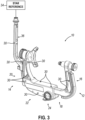
- FIGS. 2-4 illustrate a first exemplary HFD in the form of a skull clamp (10). While the present example illustrates the HFD as a U-shaped skull clamp, the teachings herein may be applied to other forms of HFDs as will be understood by those of ordinary skill in the art in view of the teachings herein.
- Skull clamp (10) comprises a first arm (12) and a second arm (14).
- First arm (12) is connectable with second arm (14) to form skull clamp (10) having a U-shape.
- First arm (12) comprises an upright portion (16) and a lateral portion (18).
- second arm (14) comprises an upright portion (20) and a lateral portion (22).
- Skull clamp (10) is adjustable to accommodate a variety of head sizes by translating first arm (12) relative to second arm (14) or vice versa. Skull clamp (10) is further connectable to other structures, such as a positioning adapter or a base unit that is further connectable with an operating table, etc., by way of an attachment interface (24).
- skull clamp (10) is constructed of radiolucent material such that skull clamp (10) is compatible with various imaging modalities.
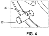
- Skull clamp (10) comprises a plurality of integrated markers (30).
- Markers (30) are positioned about first and second arms (12, 14) of skull clamp (10).
- skull clamp (10) comprises a recess (32) extending within skull clamp (10) for receiving a marker (30).
- Marker (30) may thereby be flush with an exterior surface of skull clamp (10) when marker (30) is inserted within a recess (32). While markers (30) are shown as being cylindrical, any other suitable shape may be used.
- Markers (30) are thereby positioned about a head while the head is positioned in skull clamp (10).
- Markers (30) are compatible with MRI such that they are detectable in a manner with little artifacts or distortion when seen in the MRI output.
- markers (30) may be constructed of any suitable material that interferes with a magnetic field of an MRI scanner.
- markers (30) are considered MRI markers or sometimes referred to as MR markers.
- markers (30) are also detectable in other imaging modalities, such as computed tomography (CT), x-ray, ultrasound, and combinations thereof.
- CT computed tomography
- intra-operative scans can be taken by an MRI scanner such that images of a brain can be obtained while the head is positioned within skull clamp (10), and markers (30) will be apparent in the imaging output.
- a primary active or passive reference or a star reference (34) detectable by an optical camera system of the navigation system or other detection device may also be used with skull clamp (10) to provide a reference point of each marker (30) relative to primary or star reference (34).
- star reference (34) may be selectively connected to an interface at a top portion of a support arm (36) extending outwardly from skull clamp (10).
- Support arm (36) is selectively attached or connected with skull clamp (10) in the present example; however, in other versions support arm (36) is permanently connected with skull clamp (10) or is formed as part of skull clamp (10).
- a patient has a pre-operative image obtained prior to the procedure and without the use of skull clamp (10).
- the initial registration steps can be completed as described above such that the spatial location or position of the patient is correlated or matched to the pre-operative image input to the navigation system.
- the anatomical features of the patient can be scanned or touched-off and correlated with those features in common with the pre-operative image to achieve initial patient registration as described above.
- the procedure can begin with the skull being opened to access the surgical site. At some point, another image may be desired for one or more of the reasons mentioned above.
- the patient draped and secured within skull clamp (10) the patient can be moved to the imaging device and the image can be captured, e.g., via MRI.
- the patient is returned to the operating location and re-registered with the navigation system.
- detection of primary reference marker (34) by the camera system or other detection device automatically re-registers the patient with the pre-operative image without the need to disturb the sterile drapes.
- the location and orientation of the patient is known relative to primary reference (34) based on the initial registration steps. Accordingly, when the optical camera locates primary reference (34), the navigation system's software can re-register the patient with the pre-operative image.
- the intra-operative image that includes skull clamp (10)
- markers (30) are detected in the imaging and appear in the image output that is provided to the navigation software. Because the location of markers (30) relative to primary reference marker (34) is known, the detection of primary reference marker (34) by the optical camera or other detection device of the navigation system allows the navigation software to associate the spatial location of markers (30) with the updated intra-operative image showing markers (30) in the image output.
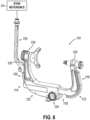
- Skull clamp (110) is adjustable to accommodate a variety of head sizes by translating first arm (112) relative to second arm (114) or vice versa. Skull clamp (110) is further connectable to other structures, such as a positioning adapter or a base unit that is further connectable with an operating table, etc., by way of an attachment interface (124).
- skull clamp (110) comprises a recess (132) extending within skull clamp (110) for receiving a marker (130).
- Marker (130) may thereby be flush with an exterior surface of skull clamp (110) when marker (130) is inserted within a recess (132).
- Markers (130) are thereby positioned about a head while the head is clamped or pinned in skull clamp (110).
- Fiducial markers (130) may be used with a navigation software system to register the spatial location of the patient's head with pre-operative and intra-operative images of the patient's head.
- Markers (130) comprise a recess (134), which may be conical, such that a probe seats properly and precisely within marker (130) when setting up spatial recognition. While markers (130) are shown as being cylindrical, any other suitable shape may be used.
- markers (130) While locating markers (130) with probe to identify their location to the navigation system, the relative position of markers (130) to one another can be checked or confirmed against the known information in the navigation system.
- the location of markers (130) is known relative to the pre-operative image and the patient. Additionally, the location of markers (130) is known relative to primary reference (34). Accordingly, the pre-operative image of the patient is registered with the patient by way of the anatomical features, and markers (130) provide a secondary set of data for possible subsequent registration of the patient securely positioned within skull clamp (10) as discussed below.
- the procedure can begin with the skull being opened to access the surgical site. At some point, another image may be desired for one or more of the reasons mentioned above.
- the patient With the patient draped and secured within skull clamp (110), the patient can be moved to the imaging device and the image can be captured, e.g., via MRI or CT. Before resuming the surgical procedure, the patient is returned to the operating location and re-registered with the navigation system.
- the navigation system's software can re-register the patient with the pre-operative image.
- the location and orientation of the patient is known relative to primary reference marker (34) based on the initial registration steps. Accordingly, when the optical camera locates primary reference (34), the navigation system's software can re-register the patient with the pre-operative image.
- re-registration can be performed in a similar manner to the initial registration in the non-sterile setup, but now in the sterile setup.
- the probe can be used to locate and touch-off on markers (130) even with the drapes in place so as to not compromise the sterile setup.
- the haptic landmarks of markers (130) aid in being able to use the probe with markers (130) despite markers (130) being covered by a drape.
- markers (130) may be detectable by an imaging modality and appearing in the intra-operative image output
- re-registration of the patient to the navigation system using the updated intra-operative image may be achieved in the same manner as described above with respect to skull clamp (10) with markers (30).
- FIGS. 8 and 9 show a third exemplary HFD in the form of a skull clamp (210). While the present example illustrates the HFD as a U-shaped skull clamp, the teachings herein may be applied to other forms of HFDs as will be understood by those of ordinary skill in the art in view of the teachings herein.
- Skull clamp (210) comprises a first arm (212) and a second arm (214).
- First arm (212) is connectable with second arm (214) to form skull clamp (210) having a U-shape.
- First arm (212) comprises an upright portion (216) and a lateral portion (218).
- second arm (214) comprises an upright portion (220) and a lateral portion (222).
- Skull clamp (210) is adjustable to accommodate a variety of head sizes by translating first arm (212) relative to second arm (214) or vice versa. Skull clamp (210) is further connectable to other structures, such as a positioning adapter or a base unit that is further connectable with an operating table, etc., by way of an attachment interface (224).
- skull clamp (210) is constructed of radiolucent material such that skull clamp (210) is compatible with various imaging modalities. In other versions skull clamp (210) is non-radiolucent.
- Skull clamp (210) comprises a plurality of integrated markers (230, 232).
- Skull clamp (210) is similar to skull clamps (10, 110), except that skull clamp (210) comprises MRI markers (230) that are detectable by an MRI scanner and fiducial markers (232) that are detectable by a registration tool of a navigation system.
- Markers (230, 232) are positioned about first and second arms (212, 214) of skull clamp (210) as shown in FIGS. 12-14 . Markers (230, 232) are thereby positioned about a head while the head is positioned in skull clamp (210).
- MRI markers (230) and fiducial markers (232) allow for registration and/or re-registration of a patient using either MRI markers (230) and/or fiducial markers (232).
- skull clamp (210) may be used in multi-modal imaging and provide the ability of re-registration as described above.
- MRI markers (230) are used with MRI
- automatic re-registration may be used as mentioned above.
- fiducial markers (232) are used for re-registration as mentioned above with respect to skull clamp (110).
- markers (232) are detectable by MRI in addition to serving as fiducial markers. In such versions with this feature for markers (232), markers (230) may be omitted, or may be included.
- a primary active or passive reference or a star reference (34) detectable by an optical camera system of the navigation system or other detection device may also be used with skull clamp (210) to provide a reference point of each marker (230, 232) relative to primary or star reference (34).
- star reference (34) may be selectively connected to an interface at a top portion of a support arm (236) extending outwardly from skull clamp (210).
- Support arm (236) is selectively attached or connected with skull clamp (210) in the present example; however, in other versions support arm (236) is permanently connected with skull clamp (210) or is formed as part of skull clamp (210).
- primary reference (34) itself, or along with support arm (236), may be removed during an intra-operative image procedure, and then reattached after for continued navigation guidance. Furthermore, this re-attachment is configured such that primary reference marker (34) attaches in the same location each time relative to HFD (210) and the patient. Accordingly, once the camera system or other detection device detects primary reference marker (34) after attachment with skull clamp (210), the location of markers (230, 232) are known by the navigation system. This is so because the navigation system software is programmed prior to the procedure to know the configuration of skull clamp (210), including the location or coordinates of markers (230, 232) relative to the primary reference (34). The navigation system may also include relative location data among various markers (230, 232) themselves based on programmed information about skull clamp (210) being input into the navigation system's software.
- a patient has a pre-operative image obtained prior to the procedure and without the use of skull clamp (210).
- the initial registration steps can be completed as described above such that the spatial location or position of the patient is correlated or matched to the pre-operative image input to the navigation system.
- skull clamp (210) with both types of markers-MR markers and fiducial markers- can be used for subsequent re-registration of the patient to pre-operative or intra-operative images in the same ways described above with respect to skull clamp (10) with MR markers (30), and/or skull clamp (110) with fiducial markers (130).
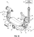
- FIGS. 10 and 11 illustrate another exemplary configuration for an HFD, where skull clamp (10) is combined with a conforming bag (300).
- Conforming bag (300) may also be referred to from time to time as a granule bag or bean bag or vacuum bag.
- skull clamp (10) includes MRI markers (30) as described above.
- skull clamp (10) includes support arm (36) and selectively connectable primary reference (34) for use with the navigation system.
- primary reference (34) is an active reference in some versions, and a passive reference in other versions.
- Bag (300) can also be used with other skull clamps or HFDs, including but not limited to skull clamps (110, 210) described above.
- bag (300) is positioned within the U-shaped void or space defined by skull clamp (10).
- Attachment features (40) are configured for selectively connecting bag (300) with skull clamp (10).
- attachment features (40) are configured so that bag (300) is positioned beneath the patient's head, it being understood that the patient may be secured with skull clamp (10) in a variety of positions depending on the procedure.
- bag (300) is positioned between the patient's head and a base of the skull clamp defined by the lateral portions described above.
- bag (300) is fastened with skull clamp (10), while in other versions bag (300) is not fixed with skull clamp (10) but instead is positioned adjacent to or in contact with skull clamp (10).
- attachment features (40) are omitted.
- Bag (300) in FIG. 11 is shown in cross-section to reveal internal components.
- granular material (315) that may take a variety of forms.
- Bag (300) includes a valve (320) that is configured to permit a vacuum to be applied to bag (300) such that bag (300) can adopt a rigid form once the air within bag (300) has been evacuated. In this manner, bag (300) is conformable to a patient's head supported by bag (300) such that bag may adopt more of a U-shape.
- bag (300) includes MRI coil (310). In the present example, coil (310) is located in the same lumen, cavity, or space in which granular material (315) is located.
- bag (300) can be modified such that coil (310) is retainable in a separate lumen, cavity, or space than granular material (315).
- Coil (310) is configured with interface (322) as seen in FIG. 10 .
- Interface (322) is configured to receive power form a power source such as a connection with computing device (51) that may power coil (310) by way of a battery power supply or connection to a standard electrical receptacle.
- Interface (322) is further configured to transmit and/or receive data, for instance by way of its connection with computing device (51) or other computing type device.
- interface (322) includes serial data features for transmission of data, as well as electrical power features for receiving power to power coil (310). In other examples, data and power may be communicated independently by separate interfaces.
- interface (322) includes a length of cord that attaches with bag and extends within the bag to connect with coil (310) directly or indirectly through another device, such as a printed circuit board that includes connections to coil (310). Still in some other versions interface (322) is substantially flush with the bag's exterior surface.
- vacuum applied to bag (300) via valve (320) can be used for patient head positioning, but such vacuum could instead or in addition be used for positioning coil (310).
- positioning coil (310) for example, it can be desirable to both locate coil (310) close to the operation site or area of interest on the patient and to secure coil (310) from movement or shifting to obtain acceptable imaging results and/or quality.
- coil (310) is positionable close to the area of interest for imaging and procedure, which positively impacts the quality of the imaging output.
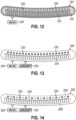
- FIG. 12 illustrates another exemplary conforming bag (301) that is usable with a skull clamp, such as skull clamps (10, 110, 210), to form another exemplary configuration for an HFD.
- bag (301) may replace bag (300) shown in FIGS. 10 and 11 .
- Bag (301) is constructed in the same manner as bag (300), but with the addition of MRI markers (330) positioned within the bag (301).
- bag (301) in FIG. 12 is shown in cross-section to reveal internal components.
- markers (330) are located in the same lumen, cavity, or space in which granular material (315) is located.
- bag (301) can be modified such that markers (330) are retainable in a separate lumen, cavity, or space than granular material (315).
- MR markers (330) Registration and re-registration of the patient, both initially and after intra-operative scans, can be achieved in the same or similar manner as described above with respect to skull clamp (10).
- Having MR markers (330) in conformable bag (301) allows MR markers to be located closer to the head of the patient, which can provide more accurate registration and re-registration with the images.
- image quality is also positively impacted based on coil (310) being within bag (301) and positioned close to the patient's head and area of interest by conforming bag (301) to the shape of the patient's head. Because bag (301) is conformable, MR markers (330) are not fixed relative to other markers in the skull clamp or primary reference (34).
- the navigation system's software can determine the spatial location of MR markers (330) by calculating the change in their location from the baseline location programmed into the software for this particular HFD equipment configuration.
- FIG. 13 illustrates another exemplary conforming bag (302) filled with granular material (315) that is usable with a skull clamp, such as skull clamps (10, 110, 210), to form another exemplary configuration for an HFD.
- bag (302) may replace bag (300) shown in FIGS. 10 and 11 .
- Bag (302) is constructed in the same manner as bag (300), but with the addition of fiducial markers (332) positioned along an outer surface of bag (302).
- bag (302) in FIG. 13 is shown with coil (310) in phantom to indicate that coil (310) is located within bag (302) while fiducial markers (332) are located on the outside surface of bag (302).
- fiducial markers (332) With the incorporation of fiducial markers (332), registration and re-registration of the patient, both initially and after intra-operative scans, can be achieved in the same or similar manner as described above with respect to skull clamp (110). Having fiducial markers (332) in conformable bag (302) allows fiducial markers to be located closer to the head of the patient, which can provide more accurate registration and re-registration with the images. Because bag (302) is conformable, fiducial markers (332) are not fixed relative to other markers in the skull clamp or primary reference (34).
- the navigation system's software can determine the spatial location of fiducial markers (332) by calculating the change in their location from the baseline location programmed into the software for this particular HFD equipment configuration.
- a probe of the navigation system can be used to contact fiducial markers (332) directly or through the sterile drapes to inform the navigation system of the location of fiducial markers (332) relative to primary reference (34).
- FIG. 14 illustrates another exemplary conforming bag (303) filled with granular material (315) that is usable with a skull clamp, such as skull clamps (10, 110, 210), to form another exemplary configuration for an HFD.
- bag (303) may replace bag (300) shown in FIGS. 10 and 11 .
- Bag (303) is constructed in the same manner as bag (300), but with the addition of fiducial markers (332) positioned along an outer surface of bag (303), and with MRI markers (330) located within bag (303). In this respect, bag (303) in FIG.
- MRI markers (330) Registration and re-registration of the patient, both initially and after intra-operative scans, can be achieved in the same or similar manner as described above with respect to skull clamp (10). Having MR markers (330) in conformable bag (304) allows MR markers to be located closer to the head of the patient, which can provide more accurate registration and re-registration with the images. Because bag (304) is conformable, MR markers (330) are not fixed relative to other markers in the skull clamp or primary reference (34).
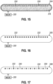
- FIG. 16 illustrates another exemplary conforming bag (305) filled with granular material (315) that is usable with a skull clamp, such as skull clamps (10, 110, 210), to form another exemplary configuration for an HFD.
- bag (305) may replace bag (300) shown in FIGS. 10 and 11 .
- Bag (305) is constructed in the same manner as bag (300), but without coil (310) and with the addition of fiducial markers (332) positioned along an outer surface of bag (305).
- an MRI coil is provided separately as part of the imaging equipment.
- fiducial markers (332) With the incorporation of fiducial markers (332), registration and re-registration of the patient, both initially and after intra-operative scans, can be achieved in the same or similar manner as described above with respect to skull clamp (110). Having fiducial markers (332) in conformable bag (305) allows fiducial markers to be located closer to the head of the patient, which can provide more accurate registration and re-registration with the images. Because bag (305) is conformable, fiducial markers (332) are not fixed relative to other markers in the skull clamp or primary reference (34).
- markers (330) are located in the same lumen, cavity, or space in which granular material (315) is located.
- bag (306) can be modified such that markers (330) are retainable in a separate lumen, cavity, or space than granular material (315).
- an MRI coil is provided separately as part of the imaging equipment.
- markers (330) and fiducial markers (332) With the incorporation of MRI markers (330) and fiducial markers (332), registration and re-registration of the patient, both initially and after intra-operative scans, can be achieved in the same or similar manner as described above with respect to skull clamp (210). Having markers (330, 332) in conformable bag (306) allows markers to be located closer to the head of the patient, which can provide more accurate registration and re-registration with the images. Because bag (306) is conformable, markers (330, 332) are not fixed relative to other markers in the skull clamp or primary reference (34).
- the navigation system's software can determine the spatial location of markers (330, 332) by calculating the change in their location from the baseline location programmed into the software for this particular HFD equipment configuration.
- a probe of the navigation system can be used to contact fiducial markers (332) directly or through the sterile drapes to inform the navigation system of the location of fiducial markers (332) relative to primary reference (34). This would not be needed for MR markers (330) as they would be apparent in the output of the MRI scan that is provided to the navigation system.
- Bag (400) in FIG. 18 is shown in cross-section to reveal internal components.
- granular material (315) that may take a variety of forms.
- Bag (400) includes a valve (320) that is configured to permit a vacuum to be applied to bag (400) such that bag (400) can adopt a rigid form once the air within bag (400) has been evacuated. In this manner, bag (400) is conformable to a patient's head supported by bag (400).
- bag (400) includes MRI coil (310).
- coil (310) is located in the same lumen, cavity, or space in which granular material (315) is located.
- bag (400) can be modified such that coil (310) is retainable in a separate lumen, cavity, or space than granular material (315).
- vacuum applied to bag (400) via valve (320) can be used for patient head positioning, but such vacuum could instead or in addition be used for positioning coil (310).
- positioning coil (310) it can be desirable to both locate coil (310) close to the operation site or area of interest on the patient, and to secure coil (310) from movement or shifting to obtain acceptable imaging results and/or quality.
- coil (310) is positionable close to the area of interest for imaging and procedure, which positively impacts the quality of the imaging output.
- bag (401) includes support arm (536) that also includes MRI markers (330). Having MR markers (330) in conformable bag (401) allows MR markers to be located closer to the head of the patient, which can provide more accurate registration and re-registration with the images. Because bag (401) is conformable, MR markers (330) are not fixed relative to other markers in the HFD or primary reference (34). However, support arm (536) includes markers (330) that remain fixed relative to primary reference (34).
- the navigation system's software can determine the spatial location of MR markers (330) within bag (401). For instance, MR markers (330) will appear in the MRI output provided to the navigation system. With primary reference (34) attached with bag (401), the optical camera of the navigation system locates primary reference (34). Because certain MR markers (330) are located on support arm (536) and fixed relative to primary reference (34), the navigation system's software calculates the change in the location of MR markers (330) within bag (401) based on the change relative to MR markers (330) on support arm (536). This information is then used for patient registration.
- FIG. 20 illustrates another exemplary conforming bag (402) filled with granular material (315) defining an HFD.
- Bag (402) is constructed in the same manner as bag (400), but with the addition of fiducial markers (332) positioned along an outer surface of bag (402).
- bag (402) in FIG. 20 is shown with coil (310) in phantom to indicate that coil (310) is located within bag (402) while fiducial markers (332) are located on the outside surface of bag (402).
- fiducial markers (332) registration and re-registration of the patient, both initially and after intra-operative scans, can be achieved in the same or similar manner as described above with respect to skull clamp (110).
- Having fiducial markers (332) in conformable bag (402) allows fiducial markers to be located closer to the head of the patient, which can provide more accurate registration and re-registration with the images.
- bag (402) is conformable, fiducial markers (332) are not fixed relative to other markers in the HFD or primary reference (34). However, the navigation system's software can determine the spatial location of fiducial markers (332) of bag (402).
- a probe of the navigation system can be used to contact fiducial markers (332) directly or through the sterile drapes to inform the navigation system of the location of fiducial markers (332) relative to primary reference (34). This information is then used for patient registration.
- FIG. 21 illustrates another exemplary conforming bag (403) filled with granular material (315) defining an HFD.
- Bag (403) is constructed in the same manner as bag (400), but with the addition of fiducial markers (332) positioned along an outer surface of bag (403), and with MRI markers (330) located within bag (403).
- bag (403) in FIG. 26 is shown with coil (310) and MRI markers (330) in phantom to indicate that coil (310) and MRI markers (330) are located within bag (403) while fiducial markers (332) are located on the outside surface of bag (403).
- markers (330) and coil (310) are located in the same lumen, cavity, or space in which granular material (315) is located.
- bag (403) can be modified such that markers (330) and/or coil (310) are retainable in a separate lumen, cavity, or space than granular material (315).
- bag (403) includes support arm (536) that also includes MRI markers (330).
- support arm (536) is shown with an interface (538) that is configured to connect with primary reference (34). In this way primary reference (34) can be removed and reinstalled in a repeatable fashion onto interface (538).
- FIG. 22 illustrates another exemplary conforming bag (404) that defines an HFD.
- Bag (404) is constructed in the same manner as bag (400), but without coil (310) within bag (404) and with the addition of MRI markers (330) positioned within the bag (304).
- bag (404) in FIG. 22 is shown in cross-section to reveal internal components.
- markers (330) are located in the same lumen, cavity, or space in which granular material (315) is located.
- bag (404) can be modified such that markers (330) are retainable in a separate lumen, cavity, or space than granular material (315).
- an MRI coil is provided separately as part of the imaging equipment.
- bag (404) includes support arm (536) that also includes MRI markers (330).
- support arm (536) is shown with an interface (538) that is configured to connect with primary reference (34). In this way primary reference (34) can be removed and reinstalled in a repeatable fashion onto interface (538).
- FIG. 23 illustrates another exemplary conforming bag (405) filled with granular material (315) that defines an HFD.
- Bag (405) is constructed in the same manner as bag (400), but without coil (310) and with the addition of fiducial markers (332) positioned along an outer surface of bag (405).
- an MRI coil is provided separately as part of the imaging equipment.
- Additional to fiducial markers (332) along the outer surface of bag (405), bag (405) is connectable with support arm (436) connectable with primary reference (34).
- With the incorporation of fiducial markers (332), registration and re-registration of the patient, both initially and after intra-operative scans, can be achieved in the same or similar manner as described above with respect to bag (402).
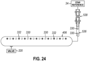
- FIG. 24 illustrates another exemplary conforming bag (406) filled with granular material (315) that defines an HFD.
- Bag (406) is constructed in the same manner as bag (400), but without coil (310) and with the addition of fiducial markers (332) positioned along an outer surface of bag (406), and with MRI markers (330) located within bag (406).
- bag (406) in FIG. 24 is shown with MRI markers (330) in phantom to indicate that MRI markers (330) are located within bag (406) while fiducial markers (332) are located on the outside surface of bag (406).
- markers (330) are located in the same lumen, cavity, or space in which granular material (315) is located.
- bag (406) can be modified such that markers (330) are retainable in a separate lumen, cavity, or space than granular material (315).
- an MRI coil is provided separately as part of the imaging equipment.
- bag (406) includes support arm (536) that also includes MRI markers (330).
- support arm (536) is shown with an interface (538) that is configured to connect with primary reference (34). In this way primary reference (34) can be removed and reinstalled in a repeatable fashion onto interface (538).
- MRI markers and fiducial markers are used where these markers are formed as part of, attached to, or otherwise incorporated with or into an HFD that may be in the form of a skull clamp, conformable bag, or other configuration.
- an HFD can be configured with one or more markers where these markers serve both as MRI markers and fiducial markers.
- any of the markers illustrated could be modified such that the markers are both MRI detectable and able to serve as fiducial markers.
- vacuum applied to the bag via valve (320) can be used for patient head positioning, but such vacuum could instead or in addition be used for positioning coil (310).
- positioning coil (310) it can be desirable to both locate coil (310) close to the operation site or area of interest on the patient, and to secure coil (310) from movement or shifting to obtain acceptable imaging results and/or quality.
- the support arm can be constructed as part of the bag in some versions such that the support arm is not removable from the bag.
- the support arm is selectively connectable or attachable with the bag.
- the support arm may include a clamping feature at its end that connects with the bag, or the bag may be constructed with an interface that engages a complementary interface of the support arm.
- other ways to attach a support arm either permanently or removably, will be apparent to those of ordinary skill in the art.
Landscapes
- Health & Medical Sciences (AREA)
- Surgery (AREA)
- Life Sciences & Earth Sciences (AREA)
- Engineering & Computer Science (AREA)
- Heart & Thoracic Surgery (AREA)
- Animal Behavior & Ethology (AREA)
- Veterinary Medicine (AREA)
- Biomedical Technology (AREA)
- Nuclear Medicine, Radiotherapy & Molecular Imaging (AREA)
- Medical Informatics (AREA)
- Molecular Biology (AREA)
- Public Health (AREA)
- General Health & Medical Sciences (AREA)
- Pathology (AREA)
- Oral & Maxillofacial Surgery (AREA)
- Robotics (AREA)
- Neurosurgery (AREA)
- Magnetic Resonance Imaging Apparatus (AREA)
Claims (8)
- Kopfstütze für einen Patienten zur Verwendung während eines medizinischen Verfahrens mit einem Patienten, wobei die Kopfstütze für einen Patienten umfasst: (a) einen Beutel (300, 301-306, 400, 401-406) mit einem Innenraum, wobei der Beutel so konfiguriert ist, dass er einen Kopf des Patienten aufnimmt und sich an den Kopf des Patienten anpasst; (b) ein anpassungsfähiges Material, das im Innenraum des Beutels angeordnet ist; (c) mindestens eine Markierung (330, 332), die zum Registrieren des Patienten mit einem Bild des Patienten konfiguriert ist, das in einem Navigationssystem verwendbar ist, und dadurch gekennzeichnet, dass (d) eine MRI-Spule (310) im Innenraum des Beutels angeordnet ist.
- Kopfstütze für Patienten nach Anspruch 1, wobei der mindestens eine Marker (330, 332) einen oder mehrere MRI-Marker (330) umfasst, die in der Tasche angeordnet sind.
- Kopfstütze für Patienten nach Anspruch 2, wobei die mindestens eine Markierung (330, 332) außerdem eine oder mehrere Referenzmarkierungen (332) umfasst, die auf einer Außenfläche des Beutels angeordnet sind.
- Kopfstütze für Patienten nach Anspruch 1, wobei die mindestens eine Markierung (330, 332) eine oder mehrere Referenzmarkierungen (332) umfasst, die auf einer Außenfläche des Beutels angeordnet sind.
- Kopfstütze für Patienten nach Anspruch 1, wobei der Beutel so konfiguriert ist, dass er eine starre Konfiguration annimmt, wenn er einem Unterdruck ausgesetzt wird.
- Die Kopfstütze für Patienten nach Anspruch 1 umfasst ferner einen primären Referenzmarker (34) eines Navigationssystems, wobei der primäre Referenzmarker selektiv mit der Tasche verbindbar ist.
- Die Kopfstütze für Patienten nach Anspruch 6 umfasst ferner einen Stützarm (36, 436, 536) mit einer Schnittstelle, die so konfiguriert ist, dass sie den primären Referenzmarker des Navigationssystems selektiv aufnimmt und festhält, wobei der Stützarm mit der Tasche koppelbar ist und wobei der Stützarm einen oder mehrere MR-Marker umfasst.
- Die Kopfstütze für Patienten nach Anspruch 1 umfasst ferner eine Schädelklemme (10), wobei der Beutel innerhalb einer U-förmigen Öffnung der Schädelklemme positionierbar ist.
Applications Claiming Priority (3)
| Application Number | Priority Date | Filing Date | Title |
|---|---|---|---|
| US201962876932P | 2019-07-22 | 2019-07-22 | |
| PCT/IB2020/000605 WO2021014212A2 (en) | 2019-07-22 | 2020-07-21 | Head stabilization device with incorporated markers |
| EP20775926.7A EP4003213A2 (de) | 2019-07-22 | 2020-07-21 | Kopfstabilisierungsvorrichtung mit eingebauten markern |
Related Parent Applications (1)
| Application Number | Title | Priority Date | Filing Date |
|---|---|---|---|
| EP20775926.7A Division EP4003213A2 (de) | 2019-07-22 | 2020-07-21 | Kopfstabilisierungsvorrichtung mit eingebauten markern |
Publications (2)
| Publication Number | Publication Date |
|---|---|
| EP4154840A1 EP4154840A1 (de) | 2023-03-29 |
| EP4154840B1 true EP4154840B1 (de) | 2025-03-19 |
Family
ID=72613937
Family Applications (2)
| Application Number | Title | Priority Date | Filing Date |
|---|---|---|---|
| EP22207689.5A Active EP4154840B1 (de) | 2019-07-22 | 2020-07-21 | Kopfstabilisierungsvorrichtung mit integrierten markern |
| EP20775926.7A Pending EP4003213A2 (de) | 2019-07-22 | 2020-07-21 | Kopfstabilisierungsvorrichtung mit eingebauten markern |
Family Applications After (1)
| Application Number | Title | Priority Date | Filing Date |
|---|---|---|---|
| EP20775926.7A Pending EP4003213A2 (de) | 2019-07-22 | 2020-07-21 | Kopfstabilisierungsvorrichtung mit eingebauten markern |
Country Status (3)
| Country | Link |
|---|---|
| US (2) | US11806196B2 (de) |
| EP (2) | EP4154840B1 (de) |
| WO (1) | WO2021014212A2 (de) |
Families Citing this family (2)
| Publication number | Priority date | Publication date | Assignee | Title |
|---|---|---|---|---|
| EP4351465A1 (de) * | 2021-06-08 | 2024-04-17 | pro med instruments GmbH | Kopfstabilisierungssystem mit erfassungsmerkmalen |
| WO2025124884A1 (en) * | 2023-12-14 | 2025-06-19 | Brainlab Ag | Head clamp system |
Family Cites Families (10)
| Publication number | Priority date | Publication date | Assignee | Title |
|---|---|---|---|---|
| US5971997A (en) | 1995-02-03 | 1999-10-26 | Radionics, Inc. | Intraoperative recalibration apparatus for stereotactic navigators |
| JP4563377B2 (ja) | 2003-02-25 | 2010-10-13 | イメージ・ガイディッド・ニューロロジクス・インコーポレーテッド | フィデューシャル・マーカ・デバイス、ツールおよび方法 |
| US8737708B2 (en) * | 2009-05-13 | 2014-05-27 | Medtronic Navigation, Inc. | System and method for automatic registration between an image and a subject |
| GB0908787D0 (en) * | 2009-05-21 | 2009-07-01 | Renishaw Plc | Head clamp for imaging and neurosurgery |
| EP2493411A4 (de) * | 2009-10-28 | 2015-04-29 | Imris Inc | Automatische registrierung von bildern für bildgesteuerte chirurgie |
| US9918797B2 (en) * | 2011-07-28 | 2018-03-20 | Brainlab Ag | Patient positioning system with an electromagnetic field generator of an electromagnetic tracking system |
| US10327708B2 (en) * | 2013-01-24 | 2019-06-25 | Kineticor, Inc. | Systems, devices, and methods for tracking and compensating for patient motion during a medical imaging scan |
| US20140275973A1 (en) * | 2013-03-15 | 2014-09-18 | Pro Med Instruments Gmbh | Mri coil drape and method of using |
| EP3062724B1 (de) | 2013-10-25 | 2018-04-18 | Brainlab AG | Magnetresonanzspuleneinheit und verfahren zu deren herstellung |
| US20160106508A1 (en) | 2014-10-15 | 2016-04-21 | Vanderbilt University | Structure for supporting a medical device on a patient during surgical procedures |
-
2020
- 2020-07-21 EP EP22207689.5A patent/EP4154840B1/de active Active
- 2020-07-21 EP EP20775926.7A patent/EP4003213A2/de active Pending
- 2020-07-21 US US16/934,443 patent/US11806196B2/en active Active
- 2020-07-21 WO PCT/IB2020/000605 patent/WO2021014212A2/en not_active Ceased
-
2022
- 2022-10-04 US US17/959,710 patent/US12533205B2/en active Active
Also Published As
| Publication number | Publication date |
|---|---|
| US20210022825A1 (en) | 2021-01-28 |
| US20230025423A1 (en) | 2023-01-26 |
| WO2021014212A2 (en) | 2021-01-28 |
| EP4003213A2 (de) | 2022-06-01 |
| US11806196B2 (en) | 2023-11-07 |
| EP4154840A1 (de) | 2023-03-29 |
| US12533205B2 (en) | 2026-01-27 |
| WO2021014212A3 (en) | 2021-04-15 |
Similar Documents
| Publication | Publication Date | Title |
|---|---|---|
| US9737235B2 (en) | System and method for image-guided navigation | |
| EP2588018B1 (de) | Registrierung eines medizinischen bildes unter verwendung einer starren inneren körperoberflàche | |
| US8238631B2 (en) | System and method for automatic registration between an image and a subject | |
| EP2131774B1 (de) | Automatische identifizierung von getrackten operationsinstrumenten mit einem elektromagnetischen lokalisationssystem | |
| US8818490B2 (en) | Instrument guiding during magnetic resonance imaging | |
| CA2483718C (en) | Hybrid imaging method to monitor medical device delivery and patient support for use in the method | |
| CN105208958B (zh) | 用于微创治疗的导航和模拟的系统和方法 | |
| US6725079B2 (en) | Dual pointer device and method for surgical navigation | |
| US10357317B2 (en) | Handheld scanner for rapid registration in a medical navigation system | |
| US9486295B2 (en) | Universal image registration interface | |
| US12533205B2 (en) | Head stabilization device with incorporated markers | |
| WO2011050456A1 (en) | Automatic registration of images for image guided surgery | |
| CN111870343A (zh) | 手术机器人系统 | |
| US20120143213A1 (en) | Surgical Apparatus | |
| JP3849853B2 (ja) | 手術用受信コイル及びこれを用いた磁気共鳴イメージング装置 | |
| Patriciu et al. | Image-guided robotic assisted interventions | |
| HK1218502B (en) | Systems and methods for navigation and simulation of minimally invasive therapy |
Legal Events
| Date | Code | Title | Description |
|---|---|---|---|
| PUAI | Public reference made under article 153(3) epc to a published international application that has entered the european phase |
Free format text: ORIGINAL CODE: 0009012 |
|
| STAA | Information on the status of an ep patent application or granted ep patent |
Free format text: STATUS: THE APPLICATION HAS BEEN PUBLISHED |
|
| AC | Divisional application: reference to earlier application |
Ref document number: 4003213 Country of ref document: EP Kind code of ref document: P |
|
| AK | Designated contracting states |
Kind code of ref document: A1 Designated state(s): AL AT BE BG CH CY CZ DE DK EE ES FI FR GB GR HR HU IE IS IT LI LT LU LV MC MK MT NL NO PL PT RO RS SE SI SK SM TR |
|
| P01 | Opt-out of the competence of the unified patent court (upc) registered |
Effective date: 20230605 |
|
| STAA | Information on the status of an ep patent application or granted ep patent |
Free format text: STATUS: REQUEST FOR EXAMINATION WAS MADE |
|
| 17P | Request for examination filed |
Effective date: 20230929 |
|
| RBV | Designated contracting states (corrected) |
Designated state(s): AL AT BE BG CH CY CZ DE DK EE ES FI FR GB GR HR HU IE IS IT LI LT LU LV MC MK MT NL NO PL PT RO RS SE SI SK SM TR |
|
| GRAP | Despatch of communication of intention to grant a patent |
Free format text: ORIGINAL CODE: EPIDOSNIGR1 |
|
| STAA | Information on the status of an ep patent application or granted ep patent |
Free format text: STATUS: GRANT OF PATENT IS INTENDED |
|
| INTG | Intention to grant announced |
Effective date: 20241018 |
|
| GRAS | Grant fee paid |
Free format text: ORIGINAL CODE: EPIDOSNIGR3 |
|
| GRAA | (expected) grant |
Free format text: ORIGINAL CODE: 0009210 |
|
| STAA | Information on the status of an ep patent application or granted ep patent |
Free format text: STATUS: THE PATENT HAS BEEN GRANTED |
|
| AC | Divisional application: reference to earlier application |
Ref document number: 4003213 Country of ref document: EP Kind code of ref document: P |
|
| AK | Designated contracting states |
Kind code of ref document: B1 Designated state(s): AL AT BE BG CH CY CZ DE DK EE ES FI FR GB GR HR HU IE IS IT LI LT LU LV MC MK MT NL NO PL PT RO RS SE SI SK SM TR |
|
| RAP3 | Party data changed (applicant data changed or rights of an application transferred) |
Owner name: PRO MED INSTRUMENTS GMBH |
|
| REG | Reference to a national code |
Ref country code: GB Ref legal event code: FG4D |
|
| REG | Reference to a national code |
Ref country code: CH Ref legal event code: EP |
|
| REG | Reference to a national code |
Ref country code: DE Ref legal event code: R081 Ref document number: 602020048174 Country of ref document: DE Owner name: PRO MED INSTRUMENTS GMBH, PART OF BLACK FOREST, DE Free format text: FORMER OWNER: ANMELDERANGABEN UNKLAR / UNVOLLSTAENDIG, 80297 MUENCHEN, DE |
|
| REG | Reference to a national code |
Ref country code: IE Ref legal event code: FG4D |
|
| REG | Reference to a national code |
Ref country code: DE Ref legal event code: R096 Ref document number: 602020048174 Country of ref document: DE |
|
| REG | Reference to a national code |
Ref country code: NL Ref legal event code: FP |
|
| PG25 | Lapsed in a contracting state [announced via postgrant information from national office to epo] |
Ref country code: RS Free format text: LAPSE BECAUSE OF FAILURE TO SUBMIT A TRANSLATION OF THE DESCRIPTION OR TO PAY THE FEE WITHIN THE PRESCRIBED TIME-LIMIT Effective date: 20250619 |
|
| PG25 | Lapsed in a contracting state [announced via postgrant information from national office to epo] |
Ref country code: FI Free format text: LAPSE BECAUSE OF FAILURE TO SUBMIT A TRANSLATION OF THE DESCRIPTION OR TO PAY THE FEE WITHIN THE PRESCRIBED TIME-LIMIT Effective date: 20250319 |
|
| REG | Reference to a national code |
Ref country code: LT Ref legal event code: MG9D |
|
| PG25 | Lapsed in a contracting state [announced via postgrant information from national office to epo] |
Ref country code: NO Free format text: LAPSE BECAUSE OF FAILURE TO SUBMIT A TRANSLATION OF THE DESCRIPTION OR TO PAY THE FEE WITHIN THE PRESCRIBED TIME-LIMIT Effective date: 20250619 |
|
| PG25 | Lapsed in a contracting state [announced via postgrant information from national office to epo] |
Ref country code: HR Free format text: LAPSE BECAUSE OF FAILURE TO SUBMIT A TRANSLATION OF THE DESCRIPTION OR TO PAY THE FEE WITHIN THE PRESCRIBED TIME-LIMIT Effective date: 20250319 |
|
| PG25 | Lapsed in a contracting state [announced via postgrant information from national office to epo] |
Ref country code: LV Free format text: LAPSE BECAUSE OF FAILURE TO SUBMIT A TRANSLATION OF THE DESCRIPTION OR TO PAY THE FEE WITHIN THE PRESCRIBED TIME-LIMIT Effective date: 20250319 |
|
| PG25 | Lapsed in a contracting state [announced via postgrant information from national office to epo] |
Ref country code: BG Free format text: LAPSE BECAUSE OF FAILURE TO SUBMIT A TRANSLATION OF THE DESCRIPTION OR TO PAY THE FEE WITHIN THE PRESCRIBED TIME-LIMIT Effective date: 20250319 Ref country code: GR Free format text: LAPSE BECAUSE OF FAILURE TO SUBMIT A TRANSLATION OF THE DESCRIPTION OR TO PAY THE FEE WITHIN THE PRESCRIBED TIME-LIMIT Effective date: 20250620 |
|
| REG | Reference to a national code |
Ref country code: AT Ref legal event code: MK05 Ref document number: 1776319 Country of ref document: AT Kind code of ref document: T Effective date: 20250319 |
|
| PGFP | Annual fee paid to national office [announced via postgrant information from national office to epo] |
Ref country code: NL Payment date: 20250726 Year of fee payment: 6 |
|
| PG25 | Lapsed in a contracting state [announced via postgrant information from national office to epo] |
Ref country code: SE Free format text: LAPSE BECAUSE OF FAILURE TO SUBMIT A TRANSLATION OF THE DESCRIPTION OR TO PAY THE FEE WITHIN THE PRESCRIBED TIME-LIMIT Effective date: 20250319 |
|
| PG25 | Lapsed in a contracting state [announced via postgrant information from national office to epo] |
Ref country code: SM Free format text: LAPSE BECAUSE OF FAILURE TO SUBMIT A TRANSLATION OF THE DESCRIPTION OR TO PAY THE FEE WITHIN THE PRESCRIBED TIME-LIMIT Effective date: 20250319 |
|
| PG25 | Lapsed in a contracting state [announced via postgrant information from national office to epo] |
Ref country code: ES Free format text: LAPSE BECAUSE OF FAILURE TO SUBMIT A TRANSLATION OF THE DESCRIPTION OR TO PAY THE FEE WITHIN THE PRESCRIBED TIME-LIMIT Effective date: 20250319 Ref country code: PT Free format text: LAPSE BECAUSE OF FAILURE TO SUBMIT A TRANSLATION OF THE DESCRIPTION OR TO PAY THE FEE WITHIN THE PRESCRIBED TIME-LIMIT Effective date: 20250721 |
|
| PGFP | Annual fee paid to national office [announced via postgrant information from national office to epo] |
Ref country code: DE Payment date: 20250729 Year of fee payment: 6 |
|
| PG25 | Lapsed in a contracting state [announced via postgrant information from national office to epo] |
Ref country code: PL Free format text: LAPSE BECAUSE OF FAILURE TO SUBMIT A TRANSLATION OF THE DESCRIPTION OR TO PAY THE FEE WITHIN THE PRESCRIBED TIME-LIMIT Effective date: 20250319 Ref country code: IT Free format text: LAPSE BECAUSE OF FAILURE TO SUBMIT A TRANSLATION OF THE DESCRIPTION OR TO PAY THE FEE WITHIN THE PRESCRIBED TIME-LIMIT Effective date: 20250319 |
|
| PG25 | Lapsed in a contracting state [announced via postgrant information from national office to epo] |
Ref country code: AT Free format text: LAPSE BECAUSE OF FAILURE TO SUBMIT A TRANSLATION OF THE DESCRIPTION OR TO PAY THE FEE WITHIN THE PRESCRIBED TIME-LIMIT Effective date: 20250319 |
|
| PG25 | Lapsed in a contracting state [announced via postgrant information from national office to epo] |
Ref country code: CZ Free format text: LAPSE BECAUSE OF FAILURE TO SUBMIT A TRANSLATION OF THE DESCRIPTION OR TO PAY THE FEE WITHIN THE PRESCRIBED TIME-LIMIT Effective date: 20250319 Ref country code: EE Free format text: LAPSE BECAUSE OF FAILURE TO SUBMIT A TRANSLATION OF THE DESCRIPTION OR TO PAY THE FEE WITHIN THE PRESCRIBED TIME-LIMIT Effective date: 20250319 |
|
| PG25 | Lapsed in a contracting state [announced via postgrant information from national office to epo] |
Ref country code: RO Free format text: LAPSE BECAUSE OF FAILURE TO SUBMIT A TRANSLATION OF THE DESCRIPTION OR TO PAY THE FEE WITHIN THE PRESCRIBED TIME-LIMIT Effective date: 20250319 |
|
| PG25 | Lapsed in a contracting state [announced via postgrant information from national office to epo] |
Ref country code: SK Free format text: LAPSE BECAUSE OF FAILURE TO SUBMIT A TRANSLATION OF THE DESCRIPTION OR TO PAY THE FEE WITHIN THE PRESCRIBED TIME-LIMIT Effective date: 20250319 |
|
| PG25 | Lapsed in a contracting state [announced via postgrant information from national office to epo] |
Ref country code: IS Free format text: LAPSE BECAUSE OF FAILURE TO SUBMIT A TRANSLATION OF THE DESCRIPTION OR TO PAY THE FEE WITHIN THE PRESCRIBED TIME-LIMIT Effective date: 20250719 |
|
| REG | Reference to a national code |
Ref country code: DE Ref legal event code: R097 Ref document number: 602020048174 Country of ref document: DE |
|
| PG25 | Lapsed in a contracting state [announced via postgrant information from national office to epo] |
Ref country code: DK Free format text: LAPSE BECAUSE OF FAILURE TO SUBMIT A TRANSLATION OF THE DESCRIPTION OR TO PAY THE FEE WITHIN THE PRESCRIBED TIME-LIMIT Effective date: 20250319 |
|
| PLBE | No opposition filed within time limit |
Free format text: ORIGINAL CODE: 0009261 |
|
| STAA | Information on the status of an ep patent application or granted ep patent |
Free format text: STATUS: NO OPPOSITION FILED WITHIN TIME LIMIT |
|
| REG | Reference to a national code |
Ref country code: CH Ref legal event code: L10 Free format text: ST27 STATUS EVENT CODE: U-0-0-L10-L00 (AS PROVIDED BY THE NATIONAL OFFICE) Effective date: 20260128 |
|
| REG | Reference to a national code |
Ref country code: CH Ref legal event code: H13 Free format text: ST27 STATUS EVENT CODE: U-0-0-H10-H13 (AS PROVIDED BY THE NATIONAL OFFICE) Effective date: 20260224 |
|
| 26N | No opposition filed |
Effective date: 20251222 |
|
| PG25 | Lapsed in a contracting state [announced via postgrant information from national office to epo] |
Ref country code: LU Free format text: LAPSE BECAUSE OF NON-PAYMENT OF DUE FEES Effective date: 20250721 |
|
| GBPC | Gb: european patent ceased through non-payment of renewal fee |
Effective date: 20250721 |
|
| REG | Reference to a national code |
Ref country code: BE Ref legal event code: MM Effective date: 20250731 |
|
| PG25 | Lapsed in a contracting state [announced via postgrant information from national office to epo] |
Ref country code: GB Free format text: LAPSE BECAUSE OF NON-PAYMENT OF DUE FEES Effective date: 20250721 |
|
| PG25 | Lapsed in a contracting state [announced via postgrant information from national office to epo] |
Ref country code: BE Free format text: LAPSE BECAUSE OF NON-PAYMENT OF DUE FEES Effective date: 20250731 |
|
| PG25 | Lapsed in a contracting state [announced via postgrant information from national office to epo] |
Ref country code: FR Free format text: LAPSE BECAUSE OF NON-PAYMENT OF DUE FEES Effective date: 20250731 |
|
| PG25 | Lapsed in a contracting state [announced via postgrant information from national office to epo] |
Ref country code: CH Free format text: LAPSE BECAUSE OF NON-PAYMENT OF DUE FEES Effective date: 20250731 |