EP4154778B1 - Oberflächenreinigungsvorrichtung - Google Patents
Oberflächenreinigungsvorrichtung Download PDFInfo
- Publication number
- EP4154778B1 EP4154778B1 EP22190067.3A EP22190067A EP4154778B1 EP 4154778 B1 EP4154778 B1 EP 4154778B1 EP 22190067 A EP22190067 A EP 22190067A EP 4154778 B1 EP4154778 B1 EP 4154778B1
- Authority
- EP
- European Patent Office
- Prior art keywords
- brushroll
- fluid
- wiper
- base
- cleaning apparatus
- Prior art date
- Legal status (The legal status is an assumption and is not a legal conclusion. Google has not performed a legal analysis and makes no representation as to the accuracy of the status listed.)
- Active
Links
Images


Classifications
-
- A—HUMAN NECESSITIES
- A47—FURNITURE; DOMESTIC ARTICLES OR APPLIANCES; COFFEE MILLS; SPICE MILLS; SUCTION CLEANERS IN GENERAL
- A47L—DOMESTIC WASHING OR CLEANING; SUCTION CLEANERS IN GENERAL
- A47L7/00—Suction cleaners adapted for additional purposes; Tables with suction openings for cleaning purposes; Containers for cleaning articles by suction; Suction cleaners adapted to cleaning of brushes; Suction cleaners adapted to taking-up liquids
- A47L7/0004—Suction cleaners adapted to take up liquids, e.g. wet or dry vacuum cleaners
- A47L7/0009—Suction cleaners adapted to take up liquids, e.g. wet or dry vacuum cleaners with means mounted on the nozzle; nozzles specially adapted for the recovery of liquid
-
- A—HUMAN NECESSITIES
- A46—BRUSHWARE
- A46B—BRUSHES
- A46B13/00—Brushes with driven brush bodies or carriers
- A46B13/001—Cylindrical or annular brush bodies
- A46B13/006—Cylindrical or annular brush bodies formed by winding a strip tuft in a helix about the body
-
- A—HUMAN NECESSITIES
- A47—FURNITURE; DOMESTIC ARTICLES OR APPLIANCES; COFFEE MILLS; SPICE MILLS; SUCTION CLEANERS IN GENERAL
- A47L—DOMESTIC WASHING OR CLEANING; SUCTION CLEANERS IN GENERAL
- A47L11/00—Machines for cleaning floors, carpets, furniture, walls, or wall coverings
- A47L11/40—Parts or details of machines not provided for in groups A47L11/02 - A47L11/38, or not restricted to one of these groups, e.g. handles, arrangements of switches, skirts, buffers, levers
- A47L11/408—Means for supplying cleaning or surface treating agents
-
- A—HUMAN NECESSITIES
- A47—FURNITURE; DOMESTIC ARTICLES OR APPLIANCES; COFFEE MILLS; SPICE MILLS; SUCTION CLEANERS IN GENERAL
- A47L—DOMESTIC WASHING OR CLEANING; SUCTION CLEANERS IN GENERAL
- A47L5/00—Structural features of suction cleaners
- A47L5/12—Structural features of suction cleaners with power-driven air-pumps or air-compressors, e.g. driven by motor vehicle engine vacuum
- A47L5/22—Structural features of suction cleaners with power-driven air-pumps or air-compressors, e.g. driven by motor vehicle engine vacuum with rotary fans
- A47L5/28—Suction cleaners with handles and nozzles fixed on the casings, e.g. wheeled suction cleaners with steering handle
- A47L5/30—Suction cleaners with handles and nozzles fixed on the casings, e.g. wheeled suction cleaners with steering handle with driven dust-loosening tools, e.g. rotating brushes
-
- A—HUMAN NECESSITIES
- A47—FURNITURE; DOMESTIC ARTICLES OR APPLIANCES; COFFEE MILLS; SPICE MILLS; SUCTION CLEANERS IN GENERAL
- A47L—DOMESTIC WASHING OR CLEANING; SUCTION CLEANERS IN GENERAL
- A47L9/00—Details or accessories of suction cleaners, e.g. mechanical means for controlling the suction or for effecting pulsating action; Storing devices specially adapted to suction cleaners or parts thereof; Carrying-vehicles specially adapted for suction cleaners
- A47L9/02—Nozzles
- A47L9/04—Nozzles with driven brushes or agitators
- A47L9/0405—Driving means for the brushes or agitators
- A47L9/0411—Driving means for the brushes or agitators driven by electric motor
-
- A—HUMAN NECESSITIES
- A47—FURNITURE; DOMESTIC ARTICLES OR APPLIANCES; COFFEE MILLS; SPICE MILLS; SUCTION CLEANERS IN GENERAL
- A47L—DOMESTIC WASHING OR CLEANING; SUCTION CLEANERS IN GENERAL
- A47L9/00—Details or accessories of suction cleaners, e.g. mechanical means for controlling the suction or for effecting pulsating action; Storing devices specially adapted to suction cleaners or parts thereof; Carrying-vehicles specially adapted for suction cleaners
- A47L9/02—Nozzles
- A47L9/04—Nozzles with driven brushes or agitators
- A47L9/0427—Gearing or transmission means therefor
- A47L9/0444—Gearing or transmission means therefor for conveying motion by endless flexible members, e.g. belts
-
- A—HUMAN NECESSITIES
- A47—FURNITURE; DOMESTIC ARTICLES OR APPLIANCES; COFFEE MILLS; SPICE MILLS; SUCTION CLEANERS IN GENERAL
- A47L—DOMESTIC WASHING OR CLEANING; SUCTION CLEANERS IN GENERAL
- A47L9/00—Details or accessories of suction cleaners, e.g. mechanical means for controlling the suction or for effecting pulsating action; Storing devices specially adapted to suction cleaners or parts thereof; Carrying-vehicles specially adapted for suction cleaners
- A47L9/02—Nozzles
- A47L9/04—Nozzles with driven brushes or agitators
- A47L9/0455—Bearing means therefor
-
- A—HUMAN NECESSITIES
- A47—FURNITURE; DOMESTIC ARTICLES OR APPLIANCES; COFFEE MILLS; SPICE MILLS; SUCTION CLEANERS IN GENERAL
- A47L—DOMESTIC WASHING OR CLEANING; SUCTION CLEANERS IN GENERAL
- A47L9/00—Details or accessories of suction cleaners, e.g. mechanical means for controlling the suction or for effecting pulsating action; Storing devices specially adapted to suction cleaners or parts thereof; Carrying-vehicles specially adapted for suction cleaners
- A47L9/02—Nozzles
- A47L9/04—Nozzles with driven brushes or agitators
- A47L9/0461—Dust-loosening tools, e.g. agitators, brushes
- A47L9/0466—Rotating tools
- A47L9/0477—Rolls
Definitions
- Multi-surface vacuum cleaners are adapted for cleaning hard floor surfaces such as tile and hardwood and soft floor surfaces such as carpet and upholstery.
- Some multi-surface vacuum cleaners comprise a fluid delivery system that delivers cleaning fluid to a surface to be cleaned and a fluid recovery system that extracts spent cleaning fluid and debris (which may include dirt, dust, stains, soil, hair, and other debris) from the surface.
- the fluid delivery system typically includes one or more fluid supply tanks for storing a supply of cleaning fluid, a fluid distributor for applying the cleaning fluid to the surface to be cleaned, and a fluid supply conduit for delivering the cleaning fluid from the fluid supply tank to the fluid distributor.
- An agitator can be provided for agitating the cleaning fluid on the surface.
- the fluid recovery system typically includes a recovery tank, a nozzle adjacent the surface to be cleaned and in fluid communication with the recovery tank through a working air conduit, and a source of suction in fluid communication with the working air conduit to draw the cleaning fluid from the surface to be cleaned and through the nozzle and the working air conduit to the recovery tank.
- Other multi-surface cleaning apparatuses include “dry” vacuum cleaners, which can clean different surface types, but do not dispense or recover liquid.
- floor cleaners include “wet” cleaners such as steam and hard floor cleaners that dispense cleaning fluid but may or may not apply suction to remove liquid and debris from the surface.
- EP3834693 and KR20140110530 are examples of prior art cleaners.
- the surface cleaning apparatus is a multi-surface wet/dry vacuum cleaner that can be used to clean hard floor surfaces such as tile and hardwood and soft floor surfaces such as carpet.
- a surface cleaning apparatus is provided with a wiper integrated with a removable brushroll and positioned to interfere with the brushroll as claimed in claim 1.
- a surface cleaning apparatus is provided with a roller integrated with a removable nozzle cover and positioned to interfere with a brushroll.
- a surface cleaning apparatus is provided with a rolling squeegee comprising a plurality of vanes, the rolling squeegee positioned forwardly of a brushroll and mounted for unidirectional rotation on a forward stroke of the apparatus.
- a surface cleaning apparatus is provided with a cantilevered squeegee, the cantilevered squeegee positioned forwardly of a brushroll and configured to bend on a forward stroke of the apparatus.
- a surface cleaning apparatus is provided with a fluid dispenser comprising a porous spray bar configured to deliver cleaning fluid onto a brushroll.
- the porous spray bar can be integrated with a nozzle cover or with a base to which a nozzle cover is coupled, and may be positioned to interfere with the brushroll.
- the brushroll may be a hybrid brushroll that includes multiple agitation materials to optimize cleaning performance on different types of surfaces to be cleaned, including hard and soft surfaces, and for different cleaning modes, including wet and dry vacuum cleaning.
- the invention generally relates to a surface cleaning apparatus for cleaning floor surfaces such as carpets, area rugs, wood, tile, and the like, and arrangements for removing excess liquid from brushroll and/or wiping liquid from a surface to be cleaned.
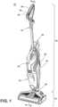
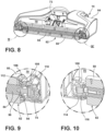
- FIGS. 1-2 show a surface cleaning apparatus 10 according to one aspect of the present disclosure.
- the surface cleaning apparatus 10 is provided with various features and improvements, including wipers, squeegees, and/or fluid dispensers that can reliably collect debris of varying size, remove excess liquid from brushroll, and/or wipe residual liquid from the floor surface to be cleaned, thereby leaving a clean and streak-free floor surface.
- the functional systems of the apparatus 10 can be arranged into any desired configuration, such as an upright device having a base and an upright body for directing the base across the surface to be cleaned, a canister device having a cleaning implement connected to a wheeled base by a vacuum hose, a portable device adapted to be hand carried by a user for cleaning relatively small areas, or a commercial device.
- Any of the aforementioned cleaners can be adapted to include a flexible vacuum hose, which can form a portion of the working air conduit between a nozzle and the suction source.
- the apparatus 10 can be an upright multi-surface wet/dry vacuum cleaner having a housing that includes an upright handle assembly or body 12 and a cleaning head or base 14 mounted to or coupled with the upright body 12 and adapted for movement across a surface to be cleaned.
- multi-surface wet/dry vacuum cleaner includes a vacuum cleaner that can be used to clean hard floor surfaces such as tile and hardwood and soft floor surfaces such as carpets and area rugs.
- the terms “upper,” “lower,” “right,” “left,” “rear,” “front,” “vertical,” “horizontal,” “inner,” “outer,” and derivatives thereof shall relate to the disclosure as oriented in FIG. 1 from the perspective of a user behind the apparatus 10, which defines the rear of the apparatus 10.
- the disclosure may assume various alternative orientations, except where expressly specified to the contrary.
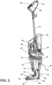
- the upright body 12 can comprise a handle 16 and a frame 18.
- the frame 18 can comprise a main support section supporting at least a supply tank 20 and a recovery tank 22, and may further support additional components of the body 12.
- the surface cleaning apparatus 10 can include a fluid delivery or supply pathway, including and at least partially defined by the supply tank 20, for storing cleaning fluid and delivering the cleaning fluid to the surface to be cleaned and a recovery pathway, including and at least partially defined by the recovery tank 22, for removing the spent cleaning fluid and debris from the surface to be cleaned and storing the spent cleaning fluid and debris until emptied by the user.
- the handle 16 can include a hand grip 24 and a trigger 26 mounted to the hand grip 24, the trigger 26 controlling the dispensing of fluid from a fluid delivery system including the supply tank 20 via an electronic or mechanical coupling with the tank 20.
- Other actuators for the fluid delivery system such as a thumb switch, can be provided instead of the trigger 26.
- the apparatus 10 can include at least one user interface (UI) through which a user can interact with the apparatus 10 and/or receive feedback information from the apparatus 10.
- UI user interface
- the UI can be electrically coupled with electrical components, including, but not limited to, circuitry electrically connected to various components of the fluid delivery and recovery systems of the surface cleaning apparatus 10, as described in further detail below.
- the apparatus 10 includes a UI with multiple input controls 30, 32 on the hand grip 24.
- One control 30 is a power button that controls the supply of power to one or more electrical components of the apparatus 10 and the other control 32 is a cleaning mode button that cycles the apparatus 10 between different cleaning modes.
- cleaning modes include a hard floor cleaning mode and an area rug or carpet cleaning mode.
- a pump 44, vacuum motor 58, and brushroll motor 72 are activated, with the vacuum motor operating at a lower power level and the pump operating at a lower flow rate in the hard floor mode. Those rates increase in the area rug cleaning mode.
- Other cleaning modes are possible.
- Other input controls such as but not limited to buttons, triggers, toggles, keys, switches, or the like, and other locations for the UI are possible.
- the apparatus 10 can include a self-cleaning mode input control 34, which initiates a self-cleaning mode of operation in which an unattended, automatic self-cleaning cycle runs.
- a self-cleaning mode input control 34 which initiates a self-cleaning mode of operation in which an unattended, automatic self-cleaning cycle runs.
- the apparatus 10 is docked on a tray and the pump 44, vacuum motor 58, and/or brushroll motor 72 operate to flush out portions of the recovery pathway of the recovery system and clean a brushroll 50 or other agitator.
- the input control 34 can comprise a button, trigger, toggle, key, switch, or the like, or any combination thereof, and can be located adjacent to the power button 30 and/or cleaning mode button 32, or can be remote from the buttons 30, 32 as shown.
- the self-cleaning mode input control 34 can be located on the upright body 12, or more specifically on the handle 16 or frame 18.
- the apparatus 10 can include a controller 36 operably coupled with the various functional systems of the apparatus, including, but not limited to, the fluid delivery and recovery systems, for controlling its operation.
- a user of the apparatus 10 can interact with the controller 36 via the UI and/or buttons 30, 32, and 34.
- the controller 36 can further be configured to execute the self-cleaning cycle for the self-cleaning mode of operation.
- the controller 36 can have software for executing the self-cleaning cycle. In the embodiment shown in FIG. 2 , the controller 36 is disposed inside the hand grip 24, although other locations are possible.
- a moveable joint assembly 38 can be formed at a lower end of the frame 18 and moveably mounts the base 14 to the upright body 12.
- the upright body 12 can pivot up and down about at least one axis relative to the base 14.
- the joint assembly 38 can alternatively comprise a universal joint, such that the upright body 12 can pivot about at least two axes relative to the base 14.
- Wiring and/or conduits can optionally supply electricity, air and/or liquid (or other fluids) between the base 14 and the upright body 12, or vice versa, and can extend though the joint assembly 38.
- the upright body 12 can pivot, via the joint assembly 38, to an upright or storage position, an example of which is shown in FIG.
- a reclined or use position in which the upright body 12 is pivoted rearwardly relative to the base 14 to form an acute angle with the surface to be cleaned. In this position, a user can partially support the apparatus by holding the hand grip 24.
- the apparatus 10 can be powered by a power supply, such as a power cord 40 plugged into a household power outlet.
- a power supply such as a power cord 40 plugged into a household power outlet.
- the apparatus 10 can be powered by a battery, preferably a rechargeable battery, for cordless operation.
- the fluid delivery system of the apparatus 10 is configured to deliver cleaning fluid from the supply tank 20 to a surface to be cleaned, and can include a fluid delivery or supply pathway.
- the supply tank 20 includes a supply chamber for holding cleaning fluid.
- the cleaning fluid can comprise one or more of any suitable cleaning liquids, including, but not limited to, water, compositions, concentrated detergent, diluted detergent, etc., and mixtures thereof.
- the liquid can comprise a mixture of water and concentrated detergent.
- supply tank 20 can include multiple supply chambers, such as one chamber containing water and another chamber containing a cleaning agent.
- the apparatus 10 can comprise multiple supply tanks. It is noted that while the apparatus 10 described herein is configured to deliver a cleaning liquid, aspects of the disclosure may be applicable to floor cleaner that deliver steam. Thus, the term "cleaning fluid" may encompass both liquid and steam unless otherwise noted.
- the fluid delivery system can comprise a flow control system for controlling the flow of cleaning fluid from the supply tank 20 to a distributor 42 ( FIG. 4 ) configured to distribute or dispense the fluid.
- the flow control system can comprise the pump 44, which pressurizes the system.
- the pump 44 can be positioned within the upright body 12 or within the base 14, and is in fluid communication with the supply tank 20, for example via conduit (not shown).
- the pump 44 can be eliminated and the flow control system can comprise a gravity-feed system having a valve fluidly coupled with an outlet of the supply tank 20, whereby when valve is open, cleaning fluid will flow under the force of gravity to the distributor 42.
- the fluid delivery system can include a supply valve 46 controlling fluid flow from an outlet of the supply tank 20 to the pump 44.
- the supply valve 46 can be configured to automatically open when the supply tank 20 is seated apparatus 10 to release fluid to the fluid delivery pathway.
- the trigger 26 can be operably coupled with the flow control system such that pressing the trigger 26 will deliver cleaning fluid to the distributor 42.
- the delivery system can include a valve (not shown) in the fluid pathway extending between the pump 44 and the distributor 42, and the trigger 26 can selectively open the valve to permit fluid to flow out of the distributor 42.
- a heater (not shown) can be provided for heating the cleaning fluid prior to delivering the cleaning fluid to the surface to be cleaned.
- an in-line heater can be located downstream of the supply tank 20 and the pump 44. Other types of heaters can also be used.
- the cleaning fluid can be heated using exhaust air from a motor-cooling pathway of the recovery system.
- the recovery system is configured to remove liquid and debris from the surface to be cleaned and store the liquid and debris on the apparatus 10 for later disposal, and can include a recovery pathway having at least a dirty inlet and a clean air outlet.
- the pathway can be formed by, among other elements, a suction nozzle 54 defining the dirty inlet, a suction source 56 in fluid communication with the suction nozzle 54 for generating a working air stream, which may contain entrained liquid and/or debris, the recovery tank 22, and at least one exhaust vent 52 defining the clean air outlet.
- At least a portion of the recovery pathway between the suction nozzle 54 and the tank 22 can be formed by a conduit 48.
- a brushroll 50 is disposed in the recovery pathway at the suction nozzle 54. Other arrangements for the recovery pathway are possible.
- the recovery tank 22 is a working air treatment assembly, and removes liquid and debris from the working airstream and collects the liquid and debris for later disposal. It is understood that other types of working air treatment assemblies for removing and collecting debris and/or liquid from the working airstream for later disposal can be used, such as a cyclonic separator, a centrifugal separator, a bulk separator, a filter bag, or a water-bath separator.
- the type of working air treatment assembly may depend on the type of floor cleaner, whether the apparatus performs dry cleaning, wet cleaning, or both, and so on.
- the suction nozzle 54 can be provided on the base 14 and is adapted to be adjacent the surface to be cleaned as the base 14 moves across a surface, and is in fluid communication with the recovery tank 22, for example through conduit 48.
- a brushroll 50 can be disposed in suction nozzle 54, and therefore in the recovery pathway, with the brushroll 50 agitating the surface to be cleaned so that the debris is more easily ingested into the suction nozzle 54.
- the suction nozzle 54 positioned to recover liquid and debris indirectly from the floor surface via the brushroll 50.
- the brushroll 50 can be outside the recovery pathway, for example to mop the floor surface, with the suction nozzle 54 positioned to recover liquid and debris directly from the floor surface.
- the suction source 56 which can be a motor/fan assembly including a vacuum motor 58 and a fan 60, is provided in fluid communication with the recovery tank 22.
- the suction source 56 can be positioned within the frame 18, such as above the recovery tank 22, and is fluidly downstream of the recovery tank 22.
- the recovery system can also be provided with one or more additional filters upstream or downstream of the suction source 56.
- a pre-motor filter 62 is provided in the recovery pathway downstream of the recovery tank 22 and upstream of the suction source 56.
- a post-motor filter (not shown) can be provided in the recovery pathway downstream of the suction source 56 and upstream of the clean air outlet 52.
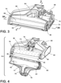
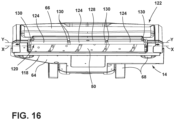
- the base 14 can include a base housing 64 supporting at least some of the components of the fluid delivery system and fluid recovery system and the suction nozzle 54 can comprise a nozzle cover 66 coupled with the base housing 64.
- the base housing 64 includes one or more wheels 68 for moving the apparatus 10 over the surface to be cleaned.
- the nozzle cover 66 can therefore define a portion of the recovery pathway and/or the dirty inlet of the recovery pathway.
- the brushroll 50 is positioned in a brush chamber 70, which may be formed by the base housing 64 and the nozzle cover 66, and/or another portion of the base 14.
- the brushroll 50 is thus positioned within the recovery pathway, and the brush chamber 70 defines a portion of the recovery pathway.
- the brushroll 50 can be operably coupled to and driven by a drive assembly 74 including a brushroll motor 72 in the base 14.
- the coupling between the brushroll 50 and the brushroll motor 72 can comprise one or more belts, gears, shafts, pulleys or combinations thereof.
- FIG. 3 a portion of the base 14 is removed so that the motor 72 and drive assembly 74 is visible.
- the vacuum motor 58 FIG. 2
- the base 14 includes a first duct 73 forming a portion of the conduit 48 between the suction nozzle 54 and the recovery tank 22.
- the first duct 73 extends through the base housing 64, from a rear side of the suction nozzle, and fluidly couples with a second duct 75.
- the first duct 73 can be a rigid duct formed at least partially by the base housing 64 and the nozzle cover 66, and/or another portion of the base 14.
- the nozzle over 66 can, for example, enclose and define a top wall 71 of the first suction duct 73.
- the nozzle over 66 can be translucent to allow visual inspection of the duct 73 and brushroll 50.
- the second duct 75 can extend through the joint assembly 38, e.g. from the base 14 to the body 12 (see FIG. 2 ), and can be formed by a flexible hose to accommodate the movement of the joint assembly 38. While shown as internal to the joint assembly 38 in the figures, in other embodiments, the second suction duct 75 can extend externally of the joint assembly 38.
- the distributor 42 for the delivery system can include one or more spray tips on the base 14, and can be positioned to deliver cleaning fluid to the brushroll 50, thereby indirectly providing cleaning fluid to the floor surface, or can be positioned to deliver cleaning fluid directly to the floor surface.
- the spray tips 42 are provided on an interior or brush-facing side of the nozzle cover 66.
- the spray tips 42 can be fed via channels of the cover 66, which terminate in connector ports 76 that couple with spray connectors 78 on the base housing 64 when the cover 66 is installed on the base housing 64.
- the spray connectors 78 are supplied with cleaning fluid via the pump 44 ( FIG. 2 ) or other flow control system of the apparatus 10.
- the spray tips 42 can optionally be oriented to spray fluid inwardly onto the brushroll 50.
- fluid distributors such as a spray manifold having multiple outlets or a spray nozzle configured to spray cleaning fluid outwardly from the base 14 in front of the surface cleaning apparatus 10.
- the brushroll is positioned in the brush chamber 70 and rotates in a direction R1 about rotational axis X.
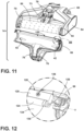
- An interference wiper 80 is integrated with the brushroll 50 and forms an assembly 82, with the assembly 82 being removable from the base housing 64 as a unit, one example of which is shown in FIG. 6 .
- the wiper 80 is configured to interface with a leading portion of the brushroll 50, as defined by the direction of rotation R1 of the brushroll 50.
- the brush chamber 70 can have a suitable clearance such that only the wiper 80 interfaces with the brushroll 50, e.g. the nozzle cover 66 does not interface with the brushroll 50.
- the interference wiper 80 is generally below the distributor 42 ( FIG.
- the wiper 80 is integrated with the brushroll 50, such that when the nozzle cover 66 is removed, the wiper 80 remains on the base 14.
- the entire assembly 82 e.g. the brushroll 50 and wiper 80 is removable as a unit.
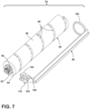
- FIG. 6 depicts the assembly 82 in a removed state. When removed, the brushroll 50 can be separated from the wiper 80, for example as shown in FIG. 7 . This permits either the brushroll 50 or the wiper 80 to be replaced individually, rather than having to replace the entire assembly 82 when one component reaches the end of its useful life.
- the brushroll 50 can be a hybrid brushroll suitable for use on both hard and soft surfaces, and for wet or dry cleaning.
- the brushroll 50 comprises a brush bar 84 supporting at least one agitation element 86, 88.
- the agitation element can comprise a plurality of bristles 86 and microfiber material 88 provided on the brush bar 84, with the microfiber material 88 arranged between the bristles 86.
- Bristles 86 can be tufted or unitary bristle strips and constructed of nylon, or any other suitable synthetic or natural fiber.
- the microfiber material 88 can be constructed of polyester, polyamides, or a conjugation of materials including polypropylene or any other suitable material known in the art from which to construct microfiber.
- the brushroll 50 can include an end assembly at a first end of the brush bar 84.
- the end assembly can, for example, include a stub shaft 90 extending from the first end of the brush bar 84 and a bearing 92 having an inner race press fitted on the stub shaft 90 and an outer race fixed in a portion of the wiper 80, as described in further detail below.
- the wiper 80 can include an elongated wiper blade 98 having opposing ends.
- the wiper blade 98 can be disposed at a forward portion of the brush chamber 70 and interfaces with a wetted portion of the rotating brushroll 50 to scrape excess liquid off before reaching the surface to be cleaned.
- the blade 98 can be positioned to interfere with the at least one agitation element 86, 88 within a forward, lower quadrant of the brushroll 50 (see FIG. 5 ).
- the wiper blade 98 can project in a rearward direction and generally parallel to the surface to be cleaned.
- the wiper blade 98 can be rigid, i.e. stiff, and non-flexible, so the wiper blade 98 does not yield or flex by engagement with the brushroll 50.
- the wiper blade 98 can be formed of rigid thermoplastic material, such as poly(methyl methacrylate) (PMMA), polycarbonate, or acrylonitrile butadiene styrene (ABS).
- PMMA poly(methyl methacrylate)
- ABS acrylonitrile butadiene styrene
- the wiper blade 98 can be flexible.
- the wiper 80 can include an end cap 100 at a first end of the wiper blade 98.
- the end cap 100 can be integrally formed with or otherwise attached to the wiper blade 98 such that the end cap 100 is removable from the brushroll 50 with the blade 98.
- an outer race of the bearing 92 is fixed in the end cap 100.
- the wiper 80 can include a handle 102 to aid in removing the assembly 82 from the brush chamber 70.
- the handle 102 can optionally include indents 104 in the sides of the handle 102 to assist in gripping the handle 102 to lift the assembly 82.
- the indents 104 can, for example, by pinched between the thumb and forefinger of the user.
- the handle 102 can be integrally formed with or otherwise attached to the end cap 100, and can project upwardly from the end cap 100 when the assembly 82 is seated in the brush chamber 70 (see FIG. 4 ) so that a user can grip the handle 102 to lift the assembly 82 up.
- the brushroll 50 can include a drive end cap 94 at a second end of the brush bar 84 that couples with a drive head 96 of the drive assembly 74.
- the drive end cap 94 and the brush bar 84 are formed or joined together such that upon drive input to the end cap 94, the brush bar 84 rotates.
- the drive end cap 94 can have a splined drive connection with the drive head 96.
- Other drive connections between the brushroll 50 and drive assembly 74 are possible.
- the wiper 80 can include a cap ring 106 at a second end of the wiper blade 98 (see FIG. 7 ).
- the cap ring 106 can be integrally formed with or otherwise attached to the wiper blade 98 such that the cap ring 106 is removable from the brushroll 50 with the blade 98.
- the cap ring 106 can have a larger inner diameter than an outer diameter of the drive end cap 94.
- the cap ring 106 is fitted over a hub 108 of the drive assembly 74.
- the hub 108 can surround the drive head 96, with clearance therebetween for the drive head 96 to spin within the stationary hub 108 when motive force is applied by the brushroll motor 72.
- the cap ring 106 can be chamfered for easy lead-in when installing the assembly 82 in the brush chamber 70.
- the hub 108 can have an outer edge 110 that is beveled or chamfered and the cap ring 106 can have an inner edge 112 with a complementary bevel or chamfer, which allows for easy insertion of the hub 108 into the cap ring 106 and aids in centering the assembly 82 when coupling the drive end cap 94 with the drive head 96.
- the chamfered inner edge 112 also exposes more of the drive end cap 94 for easier coupling with the drive head 96.
- the assembly 82 can be secured in the brush chamber 70 by a latch.
- a latch Various configurations for the latch are possible.
- a portion of the latch is provided on the end cap 100, with a mating portion provided in the brush chamber 70.
- the end cap 100 can have a latch member 114 that is snap-fit within a latch receiver 116 in the brush chamber 70.
- a squeegee 118 can be mounted to the base housing 64 behind the brushroll 50 and the brush chamber 70 and is configured to contact the surface as the base 14 moves across the surface to be cleaned.
- the squeegee 118 wipes residual liquid from the surface to be cleaned so that it can be drawn into the recovery pathway via the suction nozzle 54, thereby leaving a moisture and streak-free finish on the surface to be cleaned.
- the squeegee 118 can be disposed generally orthogonal to the surface to be cleaned, or vertically.
- the squeegee 118 can be smooth as shown, or optionally comprise nubs on the end thereof. In other embodiments, the squeegee 118 is not provided in addition to the wiper 80.
- the squeegee 118 can be pliant, i.e. flexible or resilient, in order to bend readily according to the contour of the surface to be cleaned yet remain undeformed by normal use of the apparatus 10.
- the squeegee 118 can be formed of a resilient polymeric material, such as ethylene propylene diene monomer (EPDM) rubber, polyvinyl chloride (PVC), a rubber copolymer such as nitrile butadiene rubber, or any material known in the art of sufficient rigidity to remain substantially undeformed during normal use of the apparatus 10.
- EPDM ethylene propylene diene monomer
- PVC polyvinyl chloride
- a rubber copolymer such as nitrile butadiene rubber
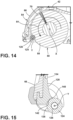
- FIGS. 11-15 show another embodiment of an interference wiper for the brushroll 50.
- the interference wiper comprises a roller 120 integrated with the nozzle cover 66 and forms a removable assembly 122, such that when the nozzle cover 66 is removed, the roller 120 is also removed.
- the entire assembly 122, e.g. the cover 66 and roller 120 is removable as a unit.
- FIG. 11 depicts the assembly 122 in a removed state.
- the roller 120 can include at least one rolling element 124 mounted for free rotation around an axis Y.
- the axis Y can be defined by a shaft 126 extending through the rolling element 124.
- the shaft 126 is fixed at opposing ends thereof to a roller mount 128.
- a bearing 130 is disposed at each opposing end of the shaft 126, and have an inner race press fitted on the shaft 126 and an outer race fixed in an open end 132 of the rolling element 124.
- the roller mount 128 is coupled to the nozzle cover 66, and can be integrally formed with or otherwise attached to an inner, or brushroll-facing, side 134 of the nozzle cover 66 to position the rolling element 124 in a suitable location for interference with the brushroll 50.
- the roller mount 128 is a separately-formed piece that is secured to the nozzle cover 66 with screws 136. Other attachments for the roller mount 128 are possible.
- the rolling element 124 is elongated and comprises a cylindrical outer surface 138 extending between the open ends 132.
- a single, elongated rolling element 124 minimizes opportunities for liquid and/or air leaks.
- the rolling element 124 may be a molded component made from any polymer with sufficient strength and resistance to chemical corrosion. Wood and metal are also suitable alternatives in some embodiments.
- the surface finish of the rolling element 124 may be smooth or textured. A smoother surface may be preferred, as it will stay cleaner and create less drag friction on the rolling element 124.
- the at least one rolling element 124 is configured to interface with a leading portion of the brushroll 50, as defined by the direction of rotation R1 of the brushroll 50.
- the rolling element 124 can be disposed at a forward portion of the brush chamber 70 and interfaces with a wetted portion of the rotating brushroll 50 to compresses the brushroll 50 while substantially blocking air and water leakage at the forward side of the brush chamber 70.
- the brush chamber 70 can have a suitable clearance such that only the rolling element 124 interfaces with the brushroll 50, e.g. the nozzle cover 66 does not interface with the brushroll 50.
- the rolling element 124 is generally below the distributor 42, such that the wetted portion brushroll 50 rotates past the rolling element 124, which compresses the microfiber 88 (or other agitation material) of the brushroll 50, and forces excess liquid out of the microfiber 88 before reaching the surface to be cleaned.
- Other locations for the rolling element 124 in relation to the brushroll 50, where the rolling element 124 is configured to interface with a portion of the brushroll 50, are possible.
- the rotating brushroll 50 can transfer force to the rolling element 124 via friction, resulting in the rolling element 124 rotating in a direction R2 about its rotational axis Y, with R2 being opposite the brushroll rotation direction R1.
- the rotational axis Y of the rolling element 124 is preferably parallel to the rotational axis X of the brushroll 50.
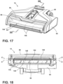
- FIGS. 17-19 show another embodiment of a base 14 for the apparatus 10.
- the base 14 includes a rolling squeegee 144 that comprises a plurality of vanes 146.
- the rolling squeegee 144 does not contact the brushroll 50, and instead is configured to provide a suction seal between the suction nozzle 54 and the floor surface, while allowing large debris to enter the suction nozzle 54, on a forward stroke of the base 14, and wipes the floor to prevent water puddles on a backward stroke of the base 14, as described in further detail below.
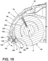
- the rolling squeegee 144 can include at least one rolling element 148 mounted for unidirectional rotation around an axis Z, the rolling element 148 comprising the multiple vanes 146 extending radially, or substantially radially, relative to the axis Z.
- the axis Z can be defined by a shaft 150 extending through the rolling element 148.
- the shaft 150 is fixed at opposing ends thereof to a squeegee mount 152.
- the rolling squeegee 144 includes multiple rolling elements 148.
- Each rolling element 148 may be mounted for individual unidrectional rotation around axis Z.
- the roller mount 152 is accordingly configured to fix multiple shafts 150 in place.
- a single rolling element 148 may be provided (see, for example, FIGS. 20-21 ) or more than two rolling elements 148 may be provided.
- one-way rotational bearings (not shown) can be fixed in the ends of each rolling element 148, and may be press fitted on the shafts 150.
- the roller mount 152 can be coupled to the nozzle cover 66, and can be integrally formed with or otherwise attached to an inner, or brushroll-facing, side 154 of the nozzle cover 66 to position the rolling element 148 in front of the brushroll 50.
- the roller mount 152 is a separately-formed piece that is secured to the nozzle cover 66. Other attachments for the roller mount 152 are possible.
- the vanes 146 can be pliant, i.e. flexible or resilient, such that the vanes 146 can bend readily according to the contour of the surface to be cleaned yet remain undeformed by normal use of the apparatus 10.
- the vanes 146 can be formed of a resilient polymeric material, such as ethylene propylene diene monomer (EPDM) rubber, polyvinyl chloride (PVC), a rubber copolymer such as nitrile butadiene rubber, or any material known in the art of sufficient rigidity to remain substantially undeformed during normal use of the apparatus 10.
- the rolling elements 148 are elongated and comprise a cylindrical inner body 156, with the plurality of vanes 146 extending from the inner body 156.
- the vanes 146 an extend radially, or substantially radially, to outer tips 158, and the tips 158 can be angled or can curve about the axis Z so that at least a portion of one vane 146 is always in contact with the floor surface.
- the vanes 146 can be spaced from each other about the periphery of the inner body 156 to define debris gaps 160 between adjacent vanes 146.
- the rolling element 148 can be a molded component, and the vanes 146 can be integrally molded with the inner body 156.
- the base 14 is moved in a forward direction F over the floor surface S, for example via a user gripping the handle 16 ( FIG. 1 ) and pushing the entire apparatus 10 forward.
- a backward stroke the base 14 is moved in a rearward direction B over the floor surface S, for example via a user gripping the handle 16 and pulling the entire apparatus 10 backward.
- the rolling elements 148 With the rolling elements 148 mounted for unidirectional rotation, the rolling elements 148 rotate in a direction R3 about axis Z on a forward stroke of the base 14 due to contact between the vanes 146 and the floor surface, with direction R3 being the same as the brushroll rotation direction R1.
- the rotational axis Z of the rolling elements 148 is preferably parallel to the rotational axis X of the brushroll 50.
- the rolling elements 148 can roll over larger debris while maintaining a tight seal between the suction nozzle 54 and the floor surface. This prevents "plowing" of larger debris while maintaining maximum suction that is effective to remove small, fine debris from the surface in addition to the larger debris.
- the rolling elements 148 stop rotating and the vanes 146 remain in a fixed orientation. Due to the design of the vanes 146, at least a portion of at least one vane 146 is in contact with the floor surface at any orientation in which the rolling elements 148 stop.
- the vane or vanes 146 in contact with the floor surface on the backward stroke squeegees or wipes residual liquid from the surface to be cleaned so that it can be drawn into the recovery pathway via the suction nozzle 54, thereby leaving a moisture and streak-free finish on the surface to be cleaned.
- the rolling squeegee 144 is provided in addition to the squeegee 118, with the squeegee 118 mounted to the base housing 64 behind the rolling squeegee 144, the brushroll 50, and the brush chamber 70.
- the squeegee 118 does not roll, but may flex back and forth on the forward and backward cleaning strokes.
- a second squeegee 118 is not provided in addition to the rolling squeegee 144.
- the rolling element 148 is disposed generally in front of and, optionally slightly below, the brushroll 50. Other locations for the rolling element 148 in relation to the brushroll 50, where the rolling element 148 does not interface with the brushroll 50, are possible. There is an air gap 162 between the rolling element 148 and the rotating brushroll 50. Preferably, the air gap 162 is small to minimize water leaks. For the embodiment shown, the air gap 162 may be on the order of 0.5 mm - 1.0 mm.
- the rolling squeegee 144 is integrated with the nozzle cover 66, such that when the nozzle cover 66 is removed, the rolling squeegee 144 is also removed.
- the squeegee 144 and cover 66 can forms a removable assembly, with the assembly being removable from the base housing 64 as a unit.
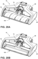
- FIG. 20A shows an embodiment where the rolling squeegee 144 is integrated with the brushroll 50, such that when the nozzle cover 66 is removed, the rolling squeegee 144 remains on the base housing 64.
- FIG. 20B shows an embodiment where the rolling squeegee 144 is integrated with the base housing 64, such that when the nozzle cover 66 and the brushroll 50 are removed, the rolling squeegee 144 remains on the base housing 64.
- FIGS. 21A-21B show another embodiment of the rolling squeegee 144 with at least one rolling element 148 mounted for unidirectional rotation around axis Z.
- the rolling element 148 has a locking gear 210 that makes contact with a locking tooth 212 when the apparatus 10 is moved in a backward stroke to prevent rotation of the rolling element 148 about the axis Z.
- the locking gear 210 can be provided on at least one, and optionally on each, end of the cylindrical inner body 156, with a corresponding tooth 212 provided in a suitable location to engage the locking gear 210.
- the tooth 212 can be disposed within a slot 214 on the squeegee mount 152 that receives the portion of the body 156, or other portion of the rolling element 148, that includes the locking gear 210.
- the slot 214 can be elongated, including being oval- or racetrack-shaped as shown, such that the rolling element 148 can translate linearly, e.g. move forward or backward, within the slot 214 to move the locking gear 210 into and out of engagement with the tooth 212.
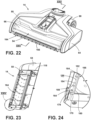
- FIGS. 22-26 show yet another embodiment of a base 14 for the apparatus 10.
- the base 14 includes a cantilevered squeegee assembly 164 that can include at least one squeegee 166 having a first end 168 that is fixed or mounted and a second end 170 that is free to bend or flex about a flexion point P.
- the cantilevered squeegee assembly 164 does not contact the brushroll 50, and instead is configured to lift up on a forward stroke of the base 14 to allow large debris to enter the suction nozzle 54, and wipes the floor to prevent water puddles on a backward stroke of the base 14, as described in further detail below.
- the mounted end 168 of the squeegee 166 can be fixed to a squeegee mount 172.
- the squeegee mount 172 is coupled to the nozzle cover 66, and can be integrally formed with or otherwise attached to an inner, or brushroll-facing, side 174 of the nozzle cover 66 to position the squeegee 166 in a suitable location forward of the brushroll 50.
- the squeegee mount 172 is a separately-formed piece that is secured to the nozzle cover 66 with one or more screws 176. Other attachments for the squeegee mount 172 are possible.
- the assembly 164 may be integrated with the brushroll 50 rather than the nozzle cover 66, or may be integrated with the base housing 64 rather than either the brushroll 50 or the nozzle cover 66.
- the free end 170 of the squeegee 166 can include a leading side 178 and an opposing trailing side 180, with the sides 178, 180 meeting and terminating at a wiper edge 182.
- a plurality of protrusions 184 are disposed on the leading side 178 and are spaced apart to define debris gaps 186 between adjacent protrusions 184.
- the protrusions 184 can project orthogonally from the leading side 178 and have a shape configured to catch on the floor surface on a forward stroke of the base 14 and to release from the floor surface on a backward stroke of the base 14.
- the squeegee 166 can be pliant, i.e. flexible or resilient, in order to bend readily on the cleaning strokes, yet remain undeformed by normal use of the apparatus 10.
- the squeegee 166 can be formed of a rubber silicone material, and may have a hardness of 70-90 Shore A.
- the protrusions 184 catch on the floor surface and the squeegee 166 bends at flexion point P. This lifts the wiper edge 182 up, and allows large debris to enter the suction nozzle 54 through the debris gaps 186 between adjacent protrusions 184.
- the protrusions 184 can comprise triangular ribs having tips 188 that dig against the floor surface on a forward stroke of the base 14, thereby bending the free end 170 of the squeegee 166 backward to lift the wiper edge 182.
- the protrusion 184 release from the floor surface, allowing the squeegee 166 to bends back and bring the wiper edge 182 down.
- the wiper edge 182 comes into contact with the floor surface and wipes residual liquid from the surface so that it can be drawn into the recovery pathway via the suction nozzle 54, thereby leaving a moisture and streak-free finish on the surface to be cleaned
- the deflection point P may be any point about which the free end 170 bends or flexes when subject to the forces of the forward and backward strokes of the base 14 during a cleaning operation.
- the bending of the squeegee 166 may depend on variables such as the type of floor surface and the speed of the base 14, and so the degree of bending and the location of the deflection point P may vary.
- the cantilevered squeegee 166 is provided in addition to the squeegee 118, with the squeegee 118 mounted to the base housing 64 behind the cantilevered squeegee 166, the brushroll 50, and the brush chamber 70.
- the squeegee 118 does not pivot as the cantilevered squeegee 166 does, but may flex back and forth on the forward and backward cleaning strokes.
- a second squeegee 118 is not provided in addition to the cantilevered squeegee 166.
- the squeegee 166 is disposed generally in front of and, optionally slightly below, the brushroll 50. Other locations for the squeegee 166 in relation to the brushroll 50, where the squeegee 166 does not interface with the brushroll 50, are possible. There is an air gap 190 between the squeegee 166 and the rotating brushroll 50. Preferably, the air gap 190 is small to minimize water leaks. For the embodiment shown, the air gap 190 may be on the order of 0.5 mm - 1.0 mm.
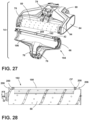
- FIGS. 27-30 show yet another embodiment of a base 14 for the apparatus 10.
- the fluid distributor 42 comprises a porous spray bar 192.
- the porous spray bar 192 delivers liquid to the brushroll 50 across the entire length of the spray bar 192 by "weeping" pressurized cleaning formula through pores, thereby providing an even wetting distribution to the brushroll.
- the spray bar 192 interferes with a portion of the brushroll 50 in order to compress the microfiber 88 (or other agitation material) of the brushroll 50, and forces the fibers to better distribute the liquid. This inference can also scrape off dirt and debris into the suction air flow of the suction nozzle 54.
- the porous spray bar 192 can be integrated with the nozzle cover 66 and forms a removable assembly 194, such that when the nozzle cover 66 is removed, the porous spray bar 192 is also removed.
- the entire assembly 194, e.g. the cover 66 and porous spray bar 192 is removable as a unit.
- FIG. 27 depicts the assembly 194 in a removed state.
- the porous spray bar 192 is provided on an interior or brush-facing side 196 of the nozzle cover 66.
- FIG. 29 shows a cleaning fluid flow path through the cover 66, with the flow path indicated by dashed line CF.
- the porous spray bar 192 is fed via channels 204 of the cover 66 which terminate in the connector ports 76 that couple with the spray connectors 78 on the base housing 64 when the cover 66 is installed on the base housing 64.
- the spray bar 192 can include inlet ports 206 that are fitted over or inserted into the open ends 200 of the body 198 for connection with the cover channels 204.
- the porous body 198 can be manufactured from various materials such as plastic, ceramic or metal, and using various techniques.
- the material for the porous body 198 can be configured to release the cleaning fluid at a relatively constant flow rate in order to evenly distribute the treating agent onto the brushroll 50.
- One preferred example is a body 198 made from sintered plastic, producing a sintered spray bar 192.
- a suitable material for the porous body 198 is a porous plastic material.
- the porous plastic can have a suitable pore size in order to achieve a consistent, even flow rate of approximately 50 - 100 ml/min.
- the material can be configured with omnidirectional matrices of plastic that form an interconnected network of open-celled pores.
- the porous body 198 can be manufactured by sintering polymer pellets.
- Some specific examples of a suitable porous plastic are polyethylene (PE) and polypropylene (PP). More specifically, a suitable material is available from POREX ® (PE or PP).
- Another example of a suitable material for the porous body 198 is a porous ceramic material made from alumina and/or silicon carbide (SiC).
- the porous body 198 can be selectively coated to precisely control the surface area where liquid delivery to the brushroll 50 is desired.
- the coating may be impervious to water, to liquid, and/or to the cleaning fluid that is dispensed by the porous spray bar 192
- a portion of the body 198 facing toward the brushroll 50 can be uncoated to allow fluid to weep through pores in this area of the body 198 and a portion of the body 198 facing away from the brushroll 50 can be coated to prevent fluid flow through pores in this area of the body 198.
- 25%-75% of outer surface area the body 198 can be coated, with the remainder uncoated to allow cleaning fluid to flow therethrough.
- a blocking member 208 is disposed at a forward portion of the brush chamber 70 and faces but does not contact the rotating brushroll 50.
- the blocking member 208 limits the gap at the front of the brush chamber 70 to minimize air and water leakage between the rotating brushroll 50 and the brush-facing side 196 of the nozzle cover 66.
- the blocking member 208 can be integrated with the nozzle cover 66 and forms the removable assembly 194 along with the cover 66 and spray bar 192.
- the blocking member 208 can be a strip that projects rearward toward, but does not contact, the brushroll 50, and that is elongated laterally to extend substantially the length of the brushroll 50
- a squeegee 118 is mounted to the base housing 64 behind the brushroll 50, the brush chamber 70, and the porous spray bar 192. In other embodiments, the squeegee 118 is not provided.
- the porous spray bar 192 interfaces with a portion of the rotating brushroll 50 to compresses the microfiber 88 (or other agitation material) of the brushroll 50, and forces excess liquid out of the microfiber 88 before reaching the surface to be cleaned.
- the brush chamber 70 can have a suitable clearance such that only the porous spray bar 192 interfaces with the brushroll 50, e.g. the nozzle cover 66 and blocking member 208 do not interface with the brushroll 50.
- the porous spray bar 192 is positioned to interfere with the brushroll at an approximately 12 o'clock position, relative to the circumference of the brushroll 50. In this position, the porous spray bar 192 compresses the top side of the brushroll 50.
- Other locations for the porous spray bar 192 in relation to the brushroll 50, where the porous spray bar 192 is configured to interface with a portion of the brushroll 50, are possible.
- FIG. 30 shows another location of the porous spray bar 192 in phantom line, where the porous spray bar 192 is positioned to interfere with the brushroll at an approximately 10 o'clock position, and interfaces with an upper front portion of the brushroll 50.
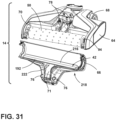
- FIGS. 31-32 show yet another embodiment of a base 14 for the apparatus 10 having the porous spray bar 192.
- the porous spray bar 192 is positioned rear of the brushroll 50, for example at an approximately 2 to 3 o'clock position, inclusive, as shown in FIG. 32 , and interferes with an upper rear portion of the brushroll 50.
- the location of fluid delivery to the brushroll 50 is closer to the suction duct 73, and given the direction of rotation R1, just after an inlet 234 to the suction duct 73.
- the porous spray bar 192 is supported by an insert 216, and the insert 216 can be integrated with the nozzle cover 66 to form a removable assembly 218, such that when the nozzle cover 66 is removed, the porous spray bar 192 and insert 216 are also removed.
- the entire assembly 218 is removable as a unit.
- FIG. 31 depicts the assembly 218 in a removed state.
- the porous spray bar 192 can have a semi-circular body manufactured from any of the materials or according to any of the methods disclosed for the previous embodiment, including, but not limited to, having a polymeric sintered body for a sintered spray bar 192.
- the spray bar can be secured to the insert 216 using various means, such as by using glue or another adhesive.
- the insert 216 includes an interior fluid channel 220, at least one inlet 222 supplied with cleaning fluid via the pump 44 ( FIG. 2 ) or other flow control system of the apparatus 10, and at least one outlet which is covered or otherwise closed by the spray bar 192, such that fluid in the channel 220 flows out of the insert 216 through the spray bar 192.
- the insert 216 has a single elongated slot 224 that is covered or otherwise closed by the spray bar 192.
- Cleaning fluid can flow into the channel 220 via the inlet 222, and flows outward through pores (not shown) in the spray bar 192.
- the insert 216 includes a front wall 226, a back wall 228, a top wall 230, and a bottom wall 232 forming the channel 220.
- the lateral ends of the walls 226-232 can be closed by a portion of the nozzle cover 66 or by additional walls (not shown), such that the channel 220 is sealed, save for the inlet 222 and the slot 224.
- the walls 226-232 joined together in a generally trapezoidal shape, although other cross-sectional configurations for the insert 216 are possible.
- the front wall 226 of the insert 216 faces the brushroll 50 and supports the spray bar 192.
- the front wall 226 can curve around, but not interfere with, a portion of the brushroll 50, and may generally follow the curvature of the brush-facing side 196 of the nozzle cover 66.
- the spray bar 192 projects outwardly from the front wall 226, and interferes with the brushroll 50.
- the inlet 222 can project from the back wall 228, or from another suitable location on the insert 216.
- the insert 216 blocks off part of the airflow path behind the brushroll 50 to minimize the open area where liquid can fling off the brushroll 50 and accumulate.
- the insert 216 can be positioned at an upper side of the duct 73, with the top wall 230 fitted tightly against the top wall 71 of the nozzle cover 66. This reduces the cross-sectional area of the inlet 234 to the duct 73 and increases the air velocity through the duct 73 for more powerful liquid recovery.
- FIG. 32 shows a portion of a cleaning fluid flow path through the base 14, with the flow path indicated by dashed line CF.
- the insert 216 is fed via the inlet 222, which can couple with a spray connector port (not show.
- an air inlet 234 of the duct 73 is defined between a lower duct wall 236 and the bottom wall 232 of the insert 216, which is disposed below the top wall 71 of the nozzle cover 66 on the base housing 64 when the cover 66 is installed on the base housing 64.
- Pressurized cleaning fluid weeps through the pores of the spray bar 192 to deliver cleaning fluid to the upper rear portion of the brushroll 50 across the entire length of the spray bar, thereby providing an even wetting distribution to the brushroll 50.
- the spray bar 192 interferes with the upper rear portion of the brushroll 50 in order to compress the microfiber 88 (or other agitation material) in this area, and force the fibers to better distribute the cleaning fluid. This inference can also scrape off dirt and debris into the suction air flow of the suction nozzle 54.
- FIGS. 33-34 show still another embodiment of a base 14 for the apparatus 10 having the porous spray bar 192.
- the porous spray bar 192 is positioned rear of the brushroll 50, for example at an approximately 4 to 5 o'clock position, inclusive, as shown in FIG. 34 , and interferes with a lower rear portion of the brushroll 50.
- the location of fluid delivery to the brushroll 50 is closer to the suction duct 73, and given the direction of rotation R1, just before the air inlet 234 to the suction duct 73.
- the porous spray bar 192 is supported by an insert 238, and the insert 238 can be positioned at a lower side of the duct 73, for example with a bottom 240 of the insert 238 fitted tightly against the bottom wall 236 of the duct 73.
- the insert 238 includes an interior fluid channel (not shown), at least one inlet 242 supplied with cleaning fluid via the pump 44 ( FIG. 2 ) or other flow control system of the apparatus 10, and at least one outlet which is covered or otherwise closed by the spray bar 192, such that fluid flows out of the insert 238 through the spray bar 192.
- the porous spray bar 192 can have a semi-circular body manufactured from any of the materials or according to any of the methods disclosed for the previous embodiment, including, but not limited to, having a polymeric sintered body for a sintered spray bar 192.
- the spray bar can be secured to the insert 238 using various means, such as by using glue or another adhesive.
- the insert 238 can be integrated with the base housing 64, such that when the nozzle cover 66 and the brushroll 50 are removed, the spray bar 192 and insert 238 remain on the base housing 64.
- FIG. 33 depicts the base housing 64 and nozzle cover 66 in phantom line.
- FIG. 34 shows a portion of a cleaning fluid flow path through the base 14, with the flow path indicated by dashed line CF.
- Pressurized cleaning fluid weeps through the pores of the spray bar 192 to deliver cleaning fluid to the lower rear portion of the brushroll 50 across the entire length of the spray bar 192, thereby providing an even wetting distribution to the brushroll 50.
- the spray bar 192 With the spray bar 192 so positioned, application of the cleaning fluid to the brushroll 50 occurs just before the air inlet 234, e.g. the area where suction air flow is the strongest.
- centrifugal forces act on the microfiber nap of the brushroll 50 causing the microfibers to extend radially outwardly and shed liquid and debris.
- the "flinging" action of the rotating brushroll 50 combined with the suction air flow removes most of the dirty liquid and debris from the brushroll 50. In other words, the brushroll 50 is rinsed off. After this rinsing, exposure to the suction air flow and the rotational speed of brushroll 50 can partially dry the brushroll. The brushroll 50 remains damp enough to clean the floor but does not over-wet or leave streaks on the floor.
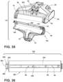
- FIGS. 35-38 show still another embodiment of a base 14 for the apparatus 10 having a fender 250 surrounding the brushroll 50.
- the fender 250 includes a fender wall 254 that extends partially around the outer circumference of the brushroll 50.
- the fluid distributor 42 dispenses cleaning fluid to the brushroll 50 through a slot 256 in the fender wall 254.
- the fluid distributor 42 comprises a porous spray bar 192 as described with respect to FIGS. 27-30 .
- Other fluid distributors are possible.
- the fender 250 helps to confine liquid that is dispensed onto and/or flung off the brushroll 50 to the area within the fender 250.
- the liquid inside the fender 250 can be absorbed by the microfiber nap of the brushroll 50, wetting the brushroll 50 evenly to wipe over the floor at the open lower side of the fender 250.
- the fender 250 can be integrated with the brushroll 50 and forms an assembly 252, with the assembly 252 being removable from the base housing 64 as a unit. When the nozzle cover 66 is removed, the fender 250 and brushroll 50 remain on the base 14.
- FIG. 36 depicts the assembly 252 in a removed state. When removed, the brushroll 50 can be separated from the fender 250. This permits the brushroll 50 and fender 250 to be thoroughly cleaned, and permits either component to be replaced individually, rather than having to replace the entire assembly 252 when one component reaches the end of its useful life. As depicted in FIG. 36 , the fender 250 can be used with a hybrid brushroll as described herein, or with other types of brushrolls.
- the fender wall 254 terminates in a front edge 258 on a front side of the brushroll 50 and terminates in a rear edge 260 on a rear side of the brushroll 50 to expose the lower portion of the brushroll 50 for contact with the surface to be cleaned.
- the rear edge 260 can be higher than the front edge 258 to expose a greater portion of the brushroll 50 at its rear side, toward the duct 73.
- the air inlet 234 of the duct 73 is defined between the rear edge 260 of the fender 250 and the lower wall 236 of the duct 73.
- the fender 250 can include an end cap 262 at a first end thereof, and which can be integrally formed with or otherwise attached to the fender wall 254 such that the end cap 262 is removable from the brushroll 50 with the fender wall 254.
- an outer race of the bearing 92 ( FIG. 7 ) is fixed in the end cap 262.
- the fender 250 can include a handle 264 to aid in removing the assembly 252 from the brush chamber 70.
- the handle 264 can optionally include indents 266 in the sides of the handle 264 to assist in gripping the handle 264 to lift the assembly 252.
- the indents 266 can, for example, by pinched between the thumb and forefinger of the user.
- the handle 264 can be integrally formed with or otherwise attached to the end cap 262, and can project upwardly from the end cap 262 when the assembly 252 is seated in the brush chamber 70 (see FIG. 35 ) so that a user can grip the handle 264 to lift the assembly 252 up.
- the cap ring 268 is fitted over a portion of the drive assembly 74, such as the hub 108 ( FIG. 9 ). Like the embodiment discussed above with respect to FIG. 9 , the cap ring 268 can be chamfered for easy lead-in when installing the assembly 252 in the brush chamber 70.
- the fender 250 can have a suitable clearance with the brushroll 50 such that the fender wall 254 does not contact the brushroll 50.
- the nozzle cover 66 can provide a suitable clearance for the fender 250 such that the fender wall 254 does not contact the brush-facing side 196 of the nozzle cover 66.
- the spray bar 192 dispenses cleaning fluid to the brushroll 50 through the slot 256 in the fender wall 254.
- the spray bar 192 can be aligned with and can project at least partially through the slot 256 to ensure that cleaning fluid reaches the brushroll 50, rather than leaking out over the outer side of the fender wall 254.
- the porous spray bar 192 can interface with a portion of the rotating brushroll 50 to compresses the microfiber 88 (or other agitation material) of the brushroll 50, and forces excess liquid out of the microfiber 88 before reaching the surface to be cleaned. In other embodiments, the spray bar 192 does not contact the brushroll 50.
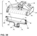
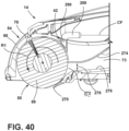
- FIGS. 39-40 show yet another embodiment of a base 14 for the apparatus 10 having a restricted air flow path for the suction duct 73 to increase air velocity within the brush chamber 70 and an angled squeegee 270.
- an inlet 272 of the duct 73 is defined between a lower duct wall 274 and an upper duct wall 276 which is formed by a bottom or underside of the nozzle cover 66.
- the duct 73 can include a narrowed section 278 downstream of the inlet 272.
- the narrowed section 278 can be formed by a portion of the upper duct wall 274 that converges toward, and then diverges away from, the lower duct wall 276.
- the narrowed section 278 can be formed by a portion of the lower duct wall 276 that converges toward, and then diverges away from, the upper duct wall 274.
- the angled squeegee 270 can be mounted to the base housing 64 behind the brushroll 50 and the brush chamber 70 and is configured to contact the surface as the base 14 moves across the surface to be cleaned.
- the squeegee 270 wipes residual liquid from the surface to be cleaned so that it can be drawn into the recovery pathway via the suction nozzle 54, thereby leaving a moisture and streak-free finish on the surface to be cleaned.
- the angled squeegee 270 is disposed obliquely to the surface to be cleaned, or at an incline rising toward the suction duct 73.
- the squeegee 270 can, in one embodiment, project forwardly from the lower duct wall 276, and may project under a rear portion of the brushroll 50.
- the angled squeegee 270 does not contact the brushroll 50, and instead is configured to provide a suction seal between the suction nozzle 54 and the floor surface, while allowing large debris to enter the suction nozzle 54, on a forward stroke of the base 14, and wipes the floor to prevent water puddles on a backward stroke of the base 14.
- the squeegee 270 is pliant, i.e. flexible or resilient, in order to bend readily according to the contour of the surface to be cleaned yet remain undeformed by normal use of the apparatus 10, and may be formed of any of the materials disclosed above with respect to squeegee 118 ( FIG. 5 ).
- the fluid distributor 42 comprises a manifold 280 having multiple outlets 282 that distribute cleaning fluid to the brushroll 50.
- the manifold 280 is positioned rear of the brushroll 50, for example at an approximately 2 to 3 o'clock position, inclusive, as shown in FIG. 40 . As such, the location of fluid delivery to the brushroll 50 is closer to the suction duct 73, and given the direction of rotation R1, just after the inlet 272 to the suction duct 73.
- the manifold 280 is therefore disposed above the inlet 272, and the squeegee is disposed below the inlet 272.
- the manifold 280 can be integrated with the nozzle cover 66 and forms a removable assembly 284, such that when the nozzle cover 66 is removed, the manifold 280 is also removed.
- the entire assembly 284 is removable as a unit.
- FIG. 39 depicts the assembly 284 in a removed state.
- the manifold 280 is provided on an interior or brush-facing side 286 of the nozzle cover 66.
- the manifold 280 can include inlet ports 288, one of which is visible in FIG. 40 , that feed cleaning fluid to the outlets 282 via an interior supply channel 290 of the manifold 280.
- a flow path, indicated by dashed line CF, can fluidly couple the inlet ports 288 with the connector ports 76 ( FIG. 39 ) that couple with the spray connectors 78 on the base housing 64 when the cover 66 is installed on the base housing 64.
- the manifold 280 does not engage or interfere with the brushroll 50.
- Other fluid distributors are possible, including a sintered spray bar.
- the different features and structures of the various embodiments of the invention may be used in combination with each other as desired, or may be used separately. That one surface cleaning apparatus is illustrated herein as having all of these features does not mean that all of these features must be used in combination, but rather done so here for brevity of description.
- the surface cleaning apparatus 10 shown herein has an upright configuration, the surface cleaning apparatus can be configured as a canister or portable unit.
- foot components such as the suction nozzle and brushroll can be provided on a cleaning head coupled with a canister unit.
- the surface cleaning apparatus can additionally have steam delivery capability.
- the various features of the different embodiments may be mixed and matched in various vacuum cleaner configurations as desired to form new embodiments, whether or not the new embodiments are expressly described.
Landscapes
- Engineering & Computer Science (AREA)
- Mechanical Engineering (AREA)
- Nozzles For Electric Vacuum Cleaners (AREA)
- Cleaning By Liquid Or Steam (AREA)
- Cleaning In General (AREA)
Claims (12)
- Oberflächenreinigungsvorrichtung (10) mit:einer Basis (14) mit einem Basisgehäuse (64), das wenigstens teilweise eine Bürstenkammer (70) bildet,einer Düsenabdeckung (66), die mit dem Basisgehäuse (64) verbunden ist, wobei die Düsenabdeckung (66) die Bürstenkammer (70) schließt,einem Bürstenwalzen/Wischer-Aufbau (82), der mit dem Basisgehäuse (64) gekoppelt ist und aufweist:eine Bürstenwalze (50), die innerhalb der Bürstenkammer (70) positioniert ist, undeinen Wischer (80), der mit der Bürstenwalze (50) integriert ist und positioniert ist, um auf die Bürstenwalze (50) einzuwirken, undeinem Flüssigkeitsverteiler (42), der dazu positioniert ist, um Reinigungsflüssigkeit auf die Bürstenwalze (50) auszugeben,wobei die Düsenabdeckung (66) von dem Basisgehäuse (64) abnehmbar ist, ohne den Bürstenwalzen/Wischer-Aufbau (82) vom Basisgehäuse (64) zu entfernen.
- Oberflächenreinigungsvorrichtung (10) nach Anspruch 1, wobei der Bürstenwalzen/Wischer-Aufbau (82) von dem Basisgehäuse (64) abnehmbar ist und wobei die Bürstenwalze (50) dazu ausgestaltet ist, bei der Abnahme vom Basisgehäuse (64) von dem Wischer (80) getrennt zu werden.
- Oberflächenreinigungsvorrichtung (10) nach einem der Ansprüche 1-2, wobei der Wischer (80) unter dem Flüssigkeitsverteiler (42) positioniert ist, so dass ein Bereich der Bürstenwalze, der von dem Flüssigkeitsverteiler (42) mit Reinigungsflüssigkeit befeuchtet ist, sich an dem Wischer (80) vorbei dreht, bevor er eine zu reinigende Oberfläche unterhalb der Basis (14) erreicht.
- Oberflächenreinigungsvorrichtung (10) nach einem der Ansprüche 1-3, wobei der Wischer (80) ein längliches Wischerblatt (98) aufweist, das in einem vorderen Bereich der Bürstenkammer (70) angeordnet ist, um auf einen vorderen Bereich der Bürstenwalze (50) einzuwirken.
- Oberflächenreinigungsvorrichtung (10) nach einem der Ansprüche 1-4, wobeidie Bürstenwalze (50) eine Bürstenstange (84), die eine Drehachse der Bürstenwalze (50) definiert, und ein Lager (92) an einem ersten Ende der Bürstenstange (84) aufweist undder Wischer (80) eine Endkappe (100) aufweist, in der das Lager (92) fixiert ist.
- Oberflächenreinigungsvorrichtung (10) nach Anspruch 5, wobeidie Bürstenwalze (50) betriebsmäßig verbunden ist mit und angetrieben wird durch einen Antriebsaufbau, wobei der Antriebsaufbau einen in der Basis (14) angeordneten Bürstenwalzenmotor (72) und einen Antriebskopf (96) aufweist,wobei die Bürstenwalze (50) an einem zweiten Ende der Bürstenstange (84) eine Antriebsendkappe (94) aufweist, die mit dem Antriebskopf (96) gekoppelt ist, undwobei der Wischer (80) einen Abschlussring (106) aufweist, der die Antriebsendkappe (94) und den damit gekoppelten Antriebskopf (96) umgibt,wobei optional
der Antriebsaufbau eine Nabe (108) aufweist, die den Antriebskopf (96) umgibt, wobei die Nabe (108) eine erste abgeschrägte Kante (110) aufweist und der Abschlussring (106) über die Nabe (108) aufgesetzt ist und eine zweite abgeschrägte Kante (112) aufweist, die komplementär zu der ersten abgeschrägten Kante (110) ist. - Oberflächenreinigungsvorrichtung (10) nach einem der Ansprüche 1-6, wobei der Wischer (80) einen Griff (102) aufweist, um die Abnahme des Bürstenwalzen/Wischer-Aufbaus (82) vom Basisgehäuse (64) zu erleichtern.
- Oberflächenreinigungsvorrichtung (10) nach einem der Ansprüche 1-7, mit einer Leitung (73), die einen Teil eines Rückführungsweges bildet, wobei die Leitung (73) von einer hinteren Seite der Bürstenkammer (70) ausgeht, wobei optional die Düsenabdeckung (66) eine obere Wand (71) der Leitung (73) definiert.
- Oberflächenreinigungsvorrichtung (10) nach einem der Ansprüche 1-8, wobei die Düsenabdeckung (66) wenigstens einen Fluidkanal aufweist, der dem Flüssigkeitsverteiler (42) Reinigungsflüssigkeit zuführt.
- Oberflächenreinigungsvorrichtung (10) nach einem der Ansprüche 1-9, wobei die Bürstenwalze (50) aufweist:ein Mikrofasermaterial (88), und wobei der Wischer (80) positioniert ist, um auf das Mikrofasermaterial (88) einzuwirken, odereine Bürstenstange (84), Borsten (86), die von der Bürstenstange (84) ausgehen, und Mikrofasermaterial (88), das zwischen den Borsten (86) vorgesehen ist, und wobei der Wischer (80) positioniert ist, um auf die Borsten (86) und das Mikrofasermaterial (88) einzuwirken.
- Oberflächenreinigungsvorrichtung (10) nach einem der Ansprüche 1-10, mit:einem Rückführungssystem einschließlich eines Rückführungsweges, eines Rückführungstanks (22) und einer Saugquelle (56), die dazu ausgestaltet ist, um einen Arbeitsluftstrom durch den Rückführungsweg zu erzeugen, wobei die Bürstenkammer (70) einen Teil des Rückführungsweges definiert und die Bürstenwalze (50) sich in dem Rückführungsweg befindet, und/odereinem Reinigungsflüssigkeit-Zufuhrsystem mit einem Vorratstank (20) in Fließverbindung mit dem Flüssigkeitsverteiler (42).
- Oberflächenreinigungsvorrichtung (10) nach einem der Ansprüche 1-10, mit einem aufrechten Körper (12), der mit der Basis (14) gekoppelt ist, wobei der aufrechte Körper (12) einen Griff (16) und wenigstens eines aufweist von:einem Auslöser (26), der die Zufuhr von Flüssigkeit aus dem Flüssigkeitsverteiler (42) steuert,einem Vorratstank (20), der dazu ausgestaltet ist, um Reinigungsflüssigkeit bereitzuhalten,einem Rückführungstank (22), der dazu ausgestaltet ist, um Flüssigkeit und von der zu reinigenden Oberfläche entfernten Schmutz zu speichern,einer Saugquelle (56), die selektiv einen Arbeitsluftstrom in einem Rückführungsweg erzeugt,eine Pumpe (44), die selektiv einen Flüssigkeitsweg unter Druck setzt, der Reinigungsflüssigkeit zum Flüssigkeitsverteiler (42) leitet,ein Gelenkaufbau (38), der den aufrechten Körper (12) schwenkbar mit der Basis (14) koppelt, um den aufrechten Körper (12) um wenigstens eine Achse zu bewegen.
Applications Claiming Priority (1)
| Application Number | Priority Date | Filing Date | Title |
|---|---|---|---|
| US202163238864P | 2021-08-31 | 2021-08-31 |
Publications (3)
| Publication Number | Publication Date |
|---|---|
| EP4154778A2 EP4154778A2 (de) | 2023-03-29 |
| EP4154778A3 EP4154778A3 (de) | 2023-08-23 |
| EP4154778B1 true EP4154778B1 (de) | 2024-12-18 |
Family
ID=82899295
Family Applications (1)
| Application Number | Title | Priority Date | Filing Date |
|---|---|---|---|
| EP22190067.3A Active EP4154778B1 (de) | 2021-08-31 | 2022-08-11 | Oberflächenreinigungsvorrichtung |
Country Status (3)
| Country | Link |
|---|---|
| US (2) | US12035873B2 (de) |
| EP (1) | EP4154778B1 (de) |
| CN (1) | CN115721220A (de) |
Families Citing this family (4)
| Publication number | Priority date | Publication date | Assignee | Title |
|---|---|---|---|---|
| US12035873B2 (en) * | 2021-08-31 | 2024-07-16 | Bissell Inc. | Surface cleaning apparatus |
| JP7577365B1 (ja) * | 2023-04-29 | 2024-11-05 | アイリスオーヤマ株式会社 | 清掃装置 |
| US20250352014A1 (en) * | 2024-05-14 | 2025-11-20 | Sharkninja Operating Llc | Directionally-aware vacuum cleaner |
| CN119308245B (zh) * | 2024-12-19 | 2025-02-25 | 山西路桥建设集团有限公司 | 一种道路护栏清洗设备 |
Family Cites Families (22)
| Publication number | Priority date | Publication date | Assignee | Title |
|---|---|---|---|---|
| CH480086A (de) * | 1967-01-05 | 1969-10-31 | Werner & Mertz Gmbh | Verfahren und Vorrichtung zur Schaumerzeugung |
| US4959628A (en) * | 1988-07-22 | 1990-09-25 | Quad Research, Inc. | Rotating electric switch actuated by fixed magnetic means, usable for a surface cleaning device |
| US6081962A (en) * | 1995-11-06 | 2000-07-04 | Bissell Homecare, Inc. | Upright water extraction cleaning machine with improved float assembly |
| US6041472A (en) * | 1995-11-06 | 2000-03-28 | Bissell Homecare, Inc. | Upright water extraction cleaning machine |
| US6968593B1 (en) * | 2001-08-14 | 2005-11-29 | Bissell Homecare, Inc. | Hand-held deep cleaner |
| US6647578B2 (en) * | 2001-09-18 | 2003-11-18 | The Hoover Company | Brush assembly removal device |
| US8402600B2 (en) * | 2006-12-13 | 2013-03-26 | Ab Electrolux | Vacuum cleaner nozzle and roller |
| JP4958572B2 (ja) * | 2007-02-07 | 2012-06-20 | パナソニック株式会社 | 掃除機用吸込具および電気掃除機 |
| RU2603600C2 (ru) | 2011-08-23 | 2016-11-27 | Конинклейке Филипс Н.В. | Чистящее устройство для чистки поверхности, содержащее щетку и элемент скребка |
| AU2014100004A4 (en) * | 2013-01-11 | 2014-01-30 | Bissell Inc. | Vacuum cleaner |
| KR101452617B1 (ko) | 2013-03-08 | 2014-10-22 | 박미경 | 미세먼지 제거용 진공청소기 |
| US9820627B2 (en) * | 2013-07-17 | 2017-11-21 | Bissell Homecare, Inc. | Vacuum cleaner with fluid distribution system |
| PL4193898T3 (pl) | 2013-12-12 | 2025-08-04 | Alfred Kärcher SE & Co. KG | Maszyna do czyszczenia podłóg z zespołem oddzielacza |
| CN108348124B (zh) * | 2015-10-10 | 2021-07-30 | 深圳市赫兹科技有限公司 | 地面清洁器及其清洁筒清理结构 |
| US10092155B2 (en) * | 2015-10-28 | 2018-10-09 | Bissell Homecare, Inc. | Surface cleaning apparatus |
| WO2019157646A1 (zh) * | 2018-02-13 | 2019-08-22 | 深圳市赫兹科技有限公司 | 扫地机器人及其两用水箱 |
| US11304581B2 (en) | 2019-01-08 | 2022-04-19 | Bissell Inc. | Surface cleaning apparatus |
| CA3101161A1 (en) | 2019-12-09 | 2021-06-09 | Bissell Inc. | Surface cleaning apparatus |
| GB2590496B (en) * | 2019-12-20 | 2023-10-04 | Techtronic Cordless Gp | A cleaner head for a cleaning appliance |
| US11122946B2 (en) * | 2021-03-04 | 2021-09-21 | Bissell Inc. | Brushroll for surface cleaning apparatus |
| EP4059399A1 (de) * | 2021-03-17 | 2022-09-21 | Koninklijke Philips N.V. | Zuführen von flüssigkeit zu mindestens einem bereich einer zu reinigenden oberfläche |
| US12035873B2 (en) * | 2021-08-31 | 2024-07-16 | Bissell Inc. | Surface cleaning apparatus |
-
2022
- 2022-08-08 US US17/882,731 patent/US12035873B2/en active Active
- 2022-08-11 EP EP22190067.3A patent/EP4154778B1/de active Active
- 2022-08-30 CN CN202211049492.4A patent/CN115721220A/zh active Pending
-
2024
- 2024-06-17 US US18/745,099 patent/US12303094B2/en active Active
Also Published As
| Publication number | Publication date |
|---|---|
| US12035873B2 (en) | 2024-07-16 |
| US20230064666A1 (en) | 2023-03-02 |
| US12303094B2 (en) | 2025-05-20 |
| CN115721220A (zh) | 2023-03-03 |
| US20240335073A1 (en) | 2024-10-10 |
| EP4154778A2 (de) | 2023-03-29 |
| EP4154778A3 (de) | 2023-08-23 |
Similar Documents
| Publication | Publication Date | Title |
|---|---|---|
| EP4154778B1 (de) | Oberflächenreinigungsvorrichtung | |
| AU2021107640A4 (en) | Surface cleaning apparatus | |
| EP3501363B1 (de) | Oberflächenreinigungsvorrichtung | |
| EP4434426B1 (de) | Oberflächenreinigungsvorrichtung mit dampfabgabe |
Legal Events
| Date | Code | Title | Description |
|---|---|---|---|
| PUAI | Public reference made under article 153(3) epc to a published international application that has entered the european phase |
Free format text: ORIGINAL CODE: 0009012 |
|
| STAA | Information on the status of an ep patent application or granted ep patent |
Free format text: STATUS: THE APPLICATION HAS BEEN PUBLISHED |
|
| AK | Designated contracting states |
Kind code of ref document: A2 Designated state(s): AL AT BE BG CH CY CZ DE DK EE ES FI FR GB GR HR HU IE IS IT LI LT LU LV MC MK MT NL NO PL PT RO RS SE SI SK SM TR |
|
| RIC1 | Information provided on ipc code assigned before grant |
Ipc: A47L 11/40 20060101ALI20230403BHEP Ipc: A47L 9/04 20060101ALI20230403BHEP Ipc: A47L 7/00 20060101AFI20230403BHEP |
|
| P01 | Opt-out of the competence of the unified patent court (upc) registered |
Effective date: 20230528 |
|
| PUAL | Search report despatched |
Free format text: ORIGINAL CODE: 0009013 |
|
| AK | Designated contracting states |
Kind code of ref document: A3 Designated state(s): AL AT BE BG CH CY CZ DE DK EE ES FI FR GB GR HR HU IE IS IT LI LT LU LV MC MK MT NL NO PL PT RO RS SE SI SK SM TR |
|
| RIC1 | Information provided on ipc code assigned before grant |
Ipc: A47L 11/40 20060101ALI20230719BHEP Ipc: A47L 9/04 20060101ALI20230719BHEP Ipc: A47L 7/00 20060101AFI20230719BHEP |
|
| STAA | Information on the status of an ep patent application or granted ep patent |
Free format text: STATUS: REQUEST FOR EXAMINATION WAS MADE |
|
| 17P | Request for examination filed |
Effective date: 20240223 |
|
| RBV | Designated contracting states (corrected) |
Designated state(s): AL AT BE BG CH CY CZ DE DK EE ES FI FR GB GR HR HU IE IS IT LI LT LU LV MC MK MT NL NO PL PT RO RS SE SI SK SM TR |
|
| GRAP | Despatch of communication of intention to grant a patent |
Free format text: ORIGINAL CODE: EPIDOSNIGR1 |
|
| STAA | Information on the status of an ep patent application or granted ep patent |
Free format text: STATUS: GRANT OF PATENT IS INTENDED |
|
| INTG | Intention to grant announced |
Effective date: 20240808 |
|
| GRAS | Grant fee paid |
Free format text: ORIGINAL CODE: EPIDOSNIGR3 |
|
| GRAA | (expected) grant |
Free format text: ORIGINAL CODE: 0009210 |
|
| STAA | Information on the status of an ep patent application or granted ep patent |
Free format text: STATUS: THE PATENT HAS BEEN GRANTED |
|
| AK | Designated contracting states |
Kind code of ref document: B1 Designated state(s): AL AT BE BG CH CY CZ DE DK EE ES FI FR GB GR HR HU IE IS IT LI LT LU LV MC MK MT NL NO PL PT RO RS SE SI SK SM TR |
|
| REG | Reference to a national code |
Ref country code: CH Ref legal event code: EP |
|
| REG | Reference to a national code |
Ref country code: DE Ref legal event code: R096 Ref document number: 602022008785 Country of ref document: DE |
|
| REG | Reference to a national code |
Ref country code: IE Ref legal event code: FG4D |
|
| REG | Reference to a national code |
Ref country code: NL Ref legal event code: FP |
|
| REG | Reference to a national code |
Ref country code: LT Ref legal event code: MG9D |
|
| PG25 | Lapsed in a contracting state [announced via postgrant information from national office to epo] |
Ref country code: HR Free format text: LAPSE BECAUSE OF FAILURE TO SUBMIT A TRANSLATION OF THE DESCRIPTION OR TO PAY THE FEE WITHIN THE PRESCRIBED TIME-LIMIT Effective date: 20241218 |
|
| PG25 | Lapsed in a contracting state [announced via postgrant information from national office to epo] |
Ref country code: FI Free format text: LAPSE BECAUSE OF FAILURE TO SUBMIT A TRANSLATION OF THE DESCRIPTION OR TO PAY THE FEE WITHIN THE PRESCRIBED TIME-LIMIT Effective date: 20241218 |
|
| PG25 | Lapsed in a contracting state [announced via postgrant information from national office to epo] |
Ref country code: BG Free format text: LAPSE BECAUSE OF FAILURE TO SUBMIT A TRANSLATION OF THE DESCRIPTION OR TO PAY THE FEE WITHIN THE PRESCRIBED TIME-LIMIT Effective date: 20241218 |
|
| PG25 | Lapsed in a contracting state [announced via postgrant information from national office to epo] |
Ref country code: NO Free format text: LAPSE BECAUSE OF FAILURE TO SUBMIT A TRANSLATION OF THE DESCRIPTION OR TO PAY THE FEE WITHIN THE PRESCRIBED TIME-LIMIT Effective date: 20250318 |
|
| PG25 | Lapsed in a contracting state [announced via postgrant information from national office to epo] |
Ref country code: LV Free format text: LAPSE BECAUSE OF FAILURE TO SUBMIT A TRANSLATION OF THE DESCRIPTION OR TO PAY THE FEE WITHIN THE PRESCRIBED TIME-LIMIT Effective date: 20241218 Ref country code: GR Free format text: LAPSE BECAUSE OF FAILURE TO SUBMIT A TRANSLATION OF THE DESCRIPTION OR TO PAY THE FEE WITHIN THE PRESCRIBED TIME-LIMIT Effective date: 20250319 |
|
| PG25 | Lapsed in a contracting state [announced via postgrant information from national office to epo] |
Ref country code: RS Free format text: LAPSE BECAUSE OF FAILURE TO SUBMIT A TRANSLATION OF THE DESCRIPTION OR TO PAY THE FEE WITHIN THE PRESCRIBED TIME-LIMIT Effective date: 20250318 |
|
| REG | Reference to a national code |
Ref country code: AT Ref legal event code: MK05 Ref document number: 1751507 Country of ref document: AT Kind code of ref document: T Effective date: 20241218 |
|
| PG25 | Lapsed in a contracting state [announced via postgrant information from national office to epo] |
Ref country code: SM Free format text: LAPSE BECAUSE OF FAILURE TO SUBMIT A TRANSLATION OF THE DESCRIPTION OR TO PAY THE FEE WITHIN THE PRESCRIBED TIME-LIMIT Effective date: 20241218 |
|
| PG25 | Lapsed in a contracting state [announced via postgrant information from national office to epo] |
Ref country code: PL Free format text: LAPSE BECAUSE OF FAILURE TO SUBMIT A TRANSLATION OF THE DESCRIPTION OR TO PAY THE FEE WITHIN THE PRESCRIBED TIME-LIMIT Effective date: 20241218 |
|
| PG25 | Lapsed in a contracting state [announced via postgrant information from national office to epo] |
Ref country code: ES Free format text: LAPSE BECAUSE OF FAILURE TO SUBMIT A TRANSLATION OF THE DESCRIPTION OR TO PAY THE FEE WITHIN THE PRESCRIBED TIME-LIMIT Effective date: 20241218 |
|
| PG25 | Lapsed in a contracting state [announced via postgrant information from national office to epo] |
Ref country code: IS Free format text: LAPSE BECAUSE OF FAILURE TO SUBMIT A TRANSLATION OF THE DESCRIPTION OR TO PAY THE FEE WITHIN THE PRESCRIBED TIME-LIMIT Effective date: 20250418 |
|
| PG25 | Lapsed in a contracting state [announced via postgrant information from national office to epo] |
Ref country code: PT Free format text: LAPSE BECAUSE OF FAILURE TO SUBMIT A TRANSLATION OF THE DESCRIPTION OR TO PAY THE FEE WITHIN THE PRESCRIBED TIME-LIMIT Effective date: 20250421 |
|
| PG25 | Lapsed in a contracting state [announced via postgrant information from national office to epo] |
Ref country code: EE Free format text: LAPSE BECAUSE OF FAILURE TO SUBMIT A TRANSLATION OF THE DESCRIPTION OR TO PAY THE FEE WITHIN THE PRESCRIBED TIME-LIMIT Effective date: 20241218 |
|
| PG25 | Lapsed in a contracting state [announced via postgrant information from national office to epo] |
Ref country code: RO Free format text: LAPSE BECAUSE OF FAILURE TO SUBMIT A TRANSLATION OF THE DESCRIPTION OR TO PAY THE FEE WITHIN THE PRESCRIBED TIME-LIMIT Effective date: 20241218 Ref country code: AT Free format text: LAPSE BECAUSE OF FAILURE TO SUBMIT A TRANSLATION OF THE DESCRIPTION OR TO PAY THE FEE WITHIN THE PRESCRIBED TIME-LIMIT Effective date: 20241218 |
|
| PG25 | Lapsed in a contracting state [announced via postgrant information from national office to epo] |
Ref country code: SK Free format text: LAPSE BECAUSE OF FAILURE TO SUBMIT A TRANSLATION OF THE DESCRIPTION OR TO PAY THE FEE WITHIN THE PRESCRIBED TIME-LIMIT Effective date: 20241218 |
|
| PG25 | Lapsed in a contracting state [announced via postgrant information from national office to epo] |
Ref country code: CZ Free format text: LAPSE BECAUSE OF FAILURE TO SUBMIT A TRANSLATION OF THE DESCRIPTION OR TO PAY THE FEE WITHIN THE PRESCRIBED TIME-LIMIT Effective date: 20241218 |
|
| PG25 | Lapsed in a contracting state [announced via postgrant information from national office to epo] |
Ref country code: IT Free format text: LAPSE BECAUSE OF FAILURE TO SUBMIT A TRANSLATION OF THE DESCRIPTION OR TO PAY THE FEE WITHIN THE PRESCRIBED TIME-LIMIT Effective date: 20241218 |
|
| PGFP | Annual fee paid to national office [announced via postgrant information from national office to epo] |
Ref country code: NL Payment date: 20250723 Year of fee payment: 4 |
|
| PG25 | Lapsed in a contracting state [announced via postgrant information from national office to epo] |
Ref country code: SE Free format text: LAPSE BECAUSE OF FAILURE TO SUBMIT A TRANSLATION OF THE DESCRIPTION OR TO PAY THE FEE WITHIN THE PRESCRIBED TIME-LIMIT Effective date: 20241218 |
|
| REG | Reference to a national code |
Ref country code: DE Ref legal event code: R097 Ref document number: 602022008785 Country of ref document: DE |
|
| PG25 | Lapsed in a contracting state [announced via postgrant information from national office to epo] |
Ref country code: DK Free format text: LAPSE BECAUSE OF FAILURE TO SUBMIT A TRANSLATION OF THE DESCRIPTION OR TO PAY THE FEE WITHIN THE PRESCRIBED TIME-LIMIT Effective date: 20241218 |
|
| PGFP | Annual fee paid to national office [announced via postgrant information from national office to epo] |
Ref country code: DE Payment date: 20250724 Year of fee payment: 4 |
|
| PGFP | Annual fee paid to national office [announced via postgrant information from national office to epo] |
Ref country code: FR Payment date: 20250725 Year of fee payment: 4 |
|
| PLBE | No opposition filed within time limit |
Free format text: ORIGINAL CODE: 0009261 |
|
| STAA | Information on the status of an ep patent application or granted ep patent |
Free format text: STATUS: NO OPPOSITION FILED WITHIN TIME LIMIT |
|
| 26N | No opposition filed |
Effective date: 20250919 |