EP4154095B1 - Ein durch kieferkontraktion betätigbares schaltsystem - Google Patents
Ein durch kieferkontraktion betätigbares schaltsystem Download PDFInfo
- Publication number
- EP4154095B1 EP4154095B1 EP21745608.6A EP21745608A EP4154095B1 EP 4154095 B1 EP4154095 B1 EP 4154095B1 EP 21745608 A EP21745608 A EP 21745608A EP 4154095 B1 EP4154095 B1 EP 4154095B1
- Authority
- EP
- European Patent Office
- Prior art keywords
- wearer
- input signals
- activation
- processor
- signal
- Prior art date
- Legal status (The legal status is an assumption and is not a legal conclusion. Google has not performed a legal analysis and makes no representation as to the accuracy of the status listed.)
- Active
Links
Images





Classifications
-
- H—ELECTRICITY
- H04—ELECTRIC COMMUNICATION TECHNIQUE
- H04W—WIRELESS COMMUNICATION NETWORKS
- H04W4/00—Services specially adapted for wireless communication networks; Facilities therefor
- H04W4/06—Selective distribution of broadcast services, e.g. multimedia broadcast multicast service [MBMS]; Services to user groups; One-way selective calling services
- H04W4/10—Push-to-Talk [PTT] or Push-On-Call services
-
- G—PHYSICS
- G06—COMPUTING OR CALCULATING; COUNTING
- G06F—ELECTRIC DIGITAL DATA PROCESSING
- G06F3/00—Input arrangements for transferring data to be processed into a form capable of being handled by the computer; Output arrangements for transferring data from processing unit to output unit, e.g. interface arrangements
- G06F3/01—Input arrangements or combined input and output arrangements for interaction between user and computer
- G06F3/011—Arrangements for interaction with the human body, e.g. for user immersion in virtual reality
- G06F3/015—Input arrangements based on nervous system activity detection, e.g. brain waves [EEG] detection, electromyograms [EMG] detection, electrodermal response detection
-
- G—PHYSICS
- G01—MEASURING; TESTING
- G01D—MEASURING NOT SPECIALLY ADAPTED FOR A SPECIFIC VARIABLE; ARRANGEMENTS FOR MEASURING TWO OR MORE VARIABLES NOT COVERED IN A SINGLE OTHER SUBCLASS; TARIFF METERING APPARATUS; MEASURING OR TESTING NOT OTHERWISE PROVIDED FOR
- G01D5/00—Mechanical means for transferring the output of a sensing member; Means for converting the output of a sensing member to another variable where the form or nature of the sensing member does not constrain the means for converting; Transducers not specially adapted for a specific variable
- G01D5/12—Mechanical means for transferring the output of a sensing member; Means for converting the output of a sensing member to another variable where the form or nature of the sensing member does not constrain the means for converting; Transducers not specially adapted for a specific variable using electric or magnetic means
- G01D5/14—Mechanical means for transferring the output of a sensing member; Means for converting the output of a sensing member to another variable where the form or nature of the sensing member does not constrain the means for converting; Transducers not specially adapted for a specific variable using electric or magnetic means influencing the magnitude of a current or voltage
- G01D5/142—Mechanical means for transferring the output of a sensing member; Means for converting the output of a sensing member to another variable where the form or nature of the sensing member does not constrain the means for converting; Transducers not specially adapted for a specific variable using electric or magnetic means influencing the magnitude of a current or voltage using Hall-effect devices
-
- G—PHYSICS
- G06—COMPUTING OR CALCULATING; COUNTING
- G06F—ELECTRIC DIGITAL DATA PROCESSING
- G06F1/00—Details not covered by groups G06F3/00 - G06F13/00 and G06F21/00
- G06F1/16—Constructional details or arrangements
- G06F1/1613—Constructional details or arrangements for portable computers
- G06F1/163—Wearable computers, e.g. on a belt
-
- G—PHYSICS
- G06—COMPUTING OR CALCULATING; COUNTING
- G06F—ELECTRIC DIGITAL DATA PROCESSING
- G06F3/00—Input arrangements for transferring data to be processed into a form capable of being handled by the computer; Output arrangements for transferring data from processing unit to output unit, e.g. interface arrangements
- G06F3/01—Input arrangements or combined input and output arrangements for interaction between user and computer
- G06F3/016—Input arrangements with force or tactile feedback as computer generated output to the user
-
- G—PHYSICS
- G08—SIGNALLING
- G08B—SIGNALLING SYSTEMS, e.g. PERSONAL CALLING SYSTEMS; ORDER TELEGRAPHS; ALARM SYSTEMS
- G08B5/00—Visible signalling systems, e.g. visible personal calling systems or remote indication of seats occupied
- G08B5/22—Visible signalling systems, e.g. visible personal calling systems or remote indication of seats occupied using electric transmission; using electromagnetic transmission
- G08B5/36—Visible signalling systems, e.g. visible personal calling systems or remote indication of seats occupied using electric transmission; using electromagnetic transmission using visible light sources
Definitions
- the present invention relates to systems and methods for operating a controlled device in a hands-free manner through volitional jaw clench actions of a wearer.
- US 2019/265802 A1 describes user interaction concepts, principles and algorithms for gestures involving facial expressions, motion or orientation of body parts, eye gaze, tightening muscles, mental activity, and other user actions.
- User interaction concepts, principles and algorithms for enabling hands-free and voice-free interaction with electronic devices are described.
- Gestures for systems using eye gaze and head tracking that can be used with augmented, mixed or virtual reality, mobile or desktop computing are described.
- US 2012/229248 A1 describes a hands-free controller, a facial expression management system, a drowsiness detection system and methods for using them.
- the controller monitors facial expressions of the user, monitors motions of the user's body, generates commands for an electronic device based on the monitored facial expressions and body motions, and communicates the commands to the electronic device.
- Monitoring facial expressions can include sensing facial muscle motions using facial expression sensors.
- Monitoring user body motions can include sensing user head motions.
- Facial expression management can includes monitoring user facial expressions, storing monitored expressions, and communicating monitored expressions to an electronic device.
- Drowsiness detection can include monitoring eye opening of the user, generating an alert when drowsiness is detected, monitoring proper usage of the device, and generating a warning when improper usage is detected.
- Embodiments of the invention include systems and methods for operating a controlled device, such as an illumination element having one or more light emitting diodes (LEDs), a push-to-talk (PTT) adapter for a two-way radio, or a two-way radio itself.
- a controlled device such as an illumination element having one or more light emitting diodes (LEDs), a push-to-talk (PTT) adapter for a two-way radio, or a two-way radio itself.
- an activation accessory for a controlled device includes a vibration motor, a wearable module including a Hall effect sensor, and a communication element.
- the wearable module includes a Hall effect sensor that is communicably coupled to a controller, which has a first output coupled to a control signal interface and a second output coupled to the vibration motor.
- the controller includes a processor and a memory coupled thereto and which stores processor-executable instructions that, when executed by the processor, cause the processor to receive and evaluate input signals from the Hall effect sensor.
- the controller evaluates the input signals to determine whether or not they represent a command for the controlled device by assessing the input signals for a signal pattern indicative of a plurality of volitional jaw clench actions of a wearer of the wearable module. If/when the processor determines that the input signals represent the command, then it decodes the command and transmits an associated control signal to the controlled device via the control signal interface as well as an activation signal to the vibration motor.
- the communication element is coupled to the control signal interface and is adapted to transmit the control signal from the processor to the controlled device.
- the communication element may be a cable having a plug configured to mate with a jack at the controlled device, or a transmitter adapted for radio frequency communication with a receiver at the controlled device.
- the activation signal for the vibration motor may be a pulse width modulated signal.
- the wearable module is supported in a mount of a headset, or another arrangement.
- a mount is moveable with respect to a frame of the headset so as to permit locating the wearable module at different positions on the wearer.
- the wearable module may include more than one Hall effect sensor, with the multiple sensors arranged with respect to one another so as to permit individual and/or group activation thereof by associated volitional jaw clench actions of the wearer.
- a visual activation indicator may be present.
- Such a visual activation indicator (e.g., an LED) may be coupled to receive a visual activation indication signal from the controller and the processor-executable instructions, when executed by the processor, may further cause the processor to perform transmit the visual activation indication signal to the visual activation indicator if/when the processor determines that the first input signals represent the command.
- the processor may evaluate the input signals against a stored library of command signal representations, where each command signal representation characterizes an associated command for the controlled device.
- the input signals may be assessed according to respective power spectral densities thereof within specified time periods.
- the input signals may be assessed according to count values of the Hall effect sensor(s) received within a specified time period.
- the input signals may be evaluated against a trained model of command signal representations, where each command signal representation characterizes an associated command for the controlled device.
- Described herein are systems and methods for hands-free operation of controlled devices, for example illumination systems, push-to-talk system, and other devices. These systems and methods are characterized, in part, by employing a switch element, e.g., a Hall effect sensor, that is positioned on or near the face of a user, overlying the area of the user's masseter muscle so that clenching/flexing of the jaw activates the switch.
- a switch element e.g., a Hall effect sensor
- the switch element is employed in combination with a headset or mask suitable for wear in a variety of contexts, including military, law enforcement, health care, and others (e.g., consumer).
- the headset or mask positions the switch element so that it overlies an area of the wearer's masseter muscle so that clenching/flexing of the wearer's jaw activates the switch, thereby allowing for hand-free operation of the controlled device.
- Other embodiments of the invention make use of the switch element as part of other head-worn illumination, imaging, and/or communication systems.
- the switch element may be positioned in locations other than over the wearer's masseter muscle, allowing activation/deactivation by means of muscles associated with a wearer's eyebrow, temple, etc.
- wearable module or a wearable electronic controller having one or more active control surfaces (e.g., Hall effect sensors, electromyography (EMG) sensors, piezo switches, etc.) is positioned to contact the right (and/or) left side of the wearer's face within an area below the ear canal to the bottom of the mandible and extending forward beneath the zygomatic arch, which is formed between the zygomatic process of the temporal bone and the temporal process of the zygomatic bone, and the zygomatic bone.
- active control surfaces e.g., Hall effect sensors, electromyography (EMG) sensors, piezo switches, etc.
- the active control surfaces are configured to detect a relaxed condition and a flexed condition of the wearer's masseter muscle(s) (see, e.g., Figure 9 ), thereby allowing the wearer to generate input signals for controlling electronic system components via masseter muscle manipulation.
- the wearable module or electronic controller is adjustable in terms of the positioning of one or more of the active control surfaces within the area(s) overlying a portion of the wearer's masseter muscle(s) and means for adjusting the contact pressure of the active control surfaces against the wearer's face may be provided.
- the wearable module may be constructed to house one or more of the electronic system components (e.g., lights, cameras, displays, laser pointers, a haptic engine in the form of a vibration motor, etc.) that is being controlled by masseter muscle manipulation.
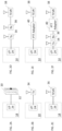
- the activation accessory 10 includes a vibration motor 12, a wearable module 14 that includes a Hall effect sensor 16, and a controller 18.
- Hall effect sensor 16 is communicably coupled to controller 18 through an analog-to-digital converter 20, which converts the analog output of the Hall effect sensor 16 to a digital signal that is provided as an input to a processor 22 of the controller.
- Processor 22 has outputs coupled to a control signal interface 24 and the vibration motor 12.
- controller 18 is also coupled to a memory 26, which stores processor-executable instructions that, when executed by processor 22, cause processor 22 to receive and evaluate input signals from the Hall effect sensor 16.
- Controller 18 i.e., processor 22 evaluates the input signals to determine whether or not they represent a command for the controlled device by assessing the input signals for a signal pattern indicative of a plurality of volitional jaw clench actions of a wearer of the wearable module 14. As more fully discussed below, if/when the processor 22 determines that the input signals from Hall effect sensor 16 represent the command for the controlled device, then processor 22 decodes the command and transmits an associated control signal to the controlled device (not shown in this view) via the control signal interface 24, as well as transmitting an activation signal to the vibration motor 12.
- the processor 22 determines that the input signals from Hall effect sensor 16 do not represent the command for the controlled device, no control signal or activation signal is transmitted and processor 22 proceeds to evaluate further/new input signals from the Hall effect sensor 16 in a like manner as the original input signals.
- the activation signal for the vibration motor is a pulse width modulated signal.
- the haptic feedback provided by vibration motor 12 in response to jaw clench actions of a wearer may also be activated by another user (e.g., through a communication to the wearer of wearable module 14) to provide a means for silent communication.
- the controlled device is an illumination element 30 made up of one or more LEDs 32.
- the processor of controller 18 is coupled to the control signal interface 24 and is adapted to transmit a control signal to the controlled device, in this case illumination element 30, via the control signal interface 24.
- the control signal interface 24 is coupled to the control signal interface 24 and is adapted to transmit a control signal to the controlled device, in this case illumination element 30, via the control signal interface 24.
- drivers and other interface elements that may be present to amplify and/or otherwise condition the control signal so that it is suitable for use with the illumination element 30.
- FIG. 2B illustrates an example in which the wearable module 14 is coupled to a transmitter 34 via the control signal interface 24.
- Transmitter 34 may be a low power / short range transmitter, such as a Bluetooth TM , Bluetooth Low Energy (BLE), Zigbee, infrared, WiFi HaLow (IEEE 802.22h), Z-wave, Thread, SigFox, Dash7, or other transmitter.
- the transmitter 34 may itself be the controlled device or, alternatively, as shown in Figure 2D , the transmitter 34 may be one component of a wireless communication system that includes a receiver 36 communicatively coupled to a controlled device, such as two-way radio 38. In such an arrangement, transmitter 34 is adapted for radio frequency communication with receiver 36 at the controlled device.
- the control signal issued by processor 22 of controller 18 is coupled to the control signal interface 24 and transmitted via a radio frequency signal from transmitter 34 to the controlled device.
- FIG 2C shows a further alternative in which the wearable module 14 is coupled directly to two-way radio 36.
- the control signal interface 24 may be coupled to the two-way radio 36 by a cable having a plug configured to mate with a jack at the two-way radio 36 (or, more generally, the controlled device).
- the wearable module 14 may function as a push-to-talk (PTT) unit for the two-way radio 36 (or, more generally, an activation switch for the controlled device).
- PTT push-to-talk
- the wearable module 14 may function as an ancillary PTT element for a PTT adapter 40 for the two-way radio 36 (or, more generally, the controlled device).
- connection between the wearable module 14 (control signal interface 24) and the PTT adapter 40 may be wired, as shown in Figure 2E , e.g., using a cable having a plug configured to mate with a jack at the PTT adapter, or wireless, using a transmitter/receiver pair 34, 36.Of course, other arrangements for communicating the control signal produced by the processor 22 (or, more generally, controller 18) of the wearable module 10 to a controlled device may be used.
- processor 22 may also communicate with and control other peripherals, such as a heads-up display, audio input/output unit, off-headset unit, etc.
- Processor 22 is a hardware-implemented module and may be a general-purpose processor, or dedicated circuitry or logic, such as a field programmable gate array (FPGA) or an application-specific integrated circuit (ASIC)), or other form of processing unit.
- Memory 26 may be a readable/writeable memory, such as an electrically erasable programable read-only memory, or other storage device.
- the wearable module 10 may be supported in a mount 42 of a headset 44, or another arrangement.
- a mount 42 may be moveable with respect to a frame 46 of the headset or a component thereof, such as earcup 48, so as to permit locating the wearable module 14 at different positions on the wearer.
- a mount 42 may be configured to position the wearable module 14 so as to be overlying an area of the wearer's masseter muscle.
- the wearable module 14 may be supported in a mask 52 (e.g., a mask used by a firefighter, a diver, an aircrew member, of another wearer), where the mask 52 is configured to position the wearable module 14 so as to be overlying an area of the wearer's masseter muscle.
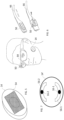
- the wearable module 14 may have an adhesive applied to a surface thereof to enable the wearable module 14 to be worn on the face or head of the wearer (see, e.g., Figure 6 ).
- Such an adhesive may, in one case, be in the form of a removeable film 54 adhered to the surface of the wearable module 14.
- the wearable module 14 may include more than one Hall effect sensor 16, with the multiple sensors arranged with respect to one another so as to permit individual and/or group activation thereof by associated volitional jaw clench actions of the wearer.
- Figure 7 illustrates a wearable module 14' that includes two Hall effect sensors 16-1, 16-2. Each Hall effect sensor is associated with a respective paddle switch 56-1, 56-2, which can be depressed through a volitional jaw clench action of the wearer. Depressing a paddle switch will cause its associated Hall effect sensor to be activated.
- a visual activation indicator 50 may be present.
- a visual activation indicator e.g., one or more LEDs
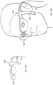
- the visual activation indicator 50 may be located on the headset 44, on a helmet 60 or an indicator panel 62 associated therewith, or as an attachment, integral or otherwise, to a pair of glasses 64 or goggles, e.g., on the temple pieces 66 thereof.
- An activation indicator of this kind is especially useful when the wearable module 14 is used to control devices such as PTT controllers/adapters associated with tactical radios or the radios themselves.
- a "microphone status LED” may be included in visual activation indicator 50 to provide a visual awareness of microphone condition. This LED emits light inside of the eyeglasses 64 which is visible only by the wearer. This provides effective light discipline in the tactical situations. Light would be visible when the microphone is in use (i.e., open) and would be extinguished when the microphone is not in use (i.e., off).
- wearable module 14 is positioned so as to be flush against the wearer's face (or nearly so), over the masseter muscle so that clenching/flexing of the jaw activates the Hall effect sensor 16.
- Power supply and control electronics for the wearable module 14 may be incorporated within the module itself, and/or in a frame or mask that supports the wearable module 14 or elsewhere.
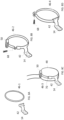
- the wearable module 14 is mounted to the earphone cup 48 of headset 44 by means of a frame 46 about the circumference of the earphone cup.
- the frame 46 may be mounted to the earphone cup 48 by means of friction fit frame 46-1, a frame 46-2, 46-3, 46-4 that is fitted by means of a screw 68, a rivet or pin 70, or other attachment means.
- the wearable module 14 may be attached to or integrated in a moveable portion of mount 42 that is rotatable about a rivet, pin or other joint or hinge and may also be flexible so as to be moved adjacent to or away from a wearer's face. This is useful to prevent unwanted actuations of Hall effect sensor 16.
- Such a moveable portion of mount 42 may be hingibly attached to a frame 46 by a spring-loaded hinge that keeps the wearable module 14 against the wearer's face even when the wearer moves his/her head unless moved away from the wearer's face by an amount sufficient to engage a detent that prevents return to a position adjacent a wearer's face unless manually adjusted by the wearer.
- a hingible arrangement may incorporate a spring-loaded hinge of any type, for example a spring-loaded piano hinge, butt hinge, barrel hinge, butterfly hinge, pivot hinge, or other arrangement.
- illumination element 50 can be attached to the inside of eyeglass temples 66 or slipped over a temple piece to contact the wearer's temple area when the eyeglasses are worn. This also provides a convenient location for vibration motor 12. From this position on the user, when the processor of wearable module 14 detects volitional facial movements of the wearer, such as clenching of the wearer's masseter muscle, which is then turned into a command signal, for activating, deactivating, or controlling a controlled device (e.g., changing the volume of audio communications or music, turning on integrated lighting modules, or answering a phone call) the vibration motor 12 may be activated to provide feedback that indicates successful recognition of the input command.
- a controlled device e.g., changing the volume of audio communications or music, turning on integrated lighting modules, or answering a phone call
- a distinct "clench language” may be programmed to control certain functions of the controlled device using specific masseter muscle clench sequences or patterns.
- the vibration motor 12 may also provide haptic feedback to the user as notification of microphone status or other enabled systems. For example, light vibrations of vibration motor 12 in a specific pattern may alert the wearer that a microphone is open , so as to prevent an "open-mic" situation where others are prevented from communicating over a common channel.
- sensors such as for wearer vital signs monitoring may also be integrated into the temple 66 to provide remote biomonitoring of the wearer, as the temple area has been proven to be an effective location for sensing certain vital signs.
- sensors may be integrated into the eyeglass temples 66, permanently attached as an accessory, or attached to the inside of the temple using adhesive tape, glue, magnets, hook and loop fasteners, screws, or a tongue and groove or dovetail profile connection mechanism.
- the sensor signal may be routed through a powered cable/tether or via a wireless connection such as Bluetooth or Near Field Magnetic Induction.
- the activation accessory does not require donning a headset or mask. Instead, the activation accessory can be worn by itself, e.g., through use of an adhesive. Incorporating the activation accessory in headsets would typically be the norm for any member of an aircraft flight or operations crew, but headsets such as the one illustrated in the above-referenced figures are not restricted to use by flight/aircraft crews and may be employed by ground forces, naval/coast guard personnel, and civilians. For example, headsets such as the ones described herein may be employed by workers in and around constructions sites, sports arenas, film and television production locations, amusement parks, and many other locations.
- FIG. 3 illustrates a headset with both left and right earphone cups, this is for purposes of example only and the present system may be used with headsets having only a single earphone cup, or one or two earpieces. Indeed, the present system may be used even with headgear that does not include any earphones or earpieces, for example attached to a band worn on the head or neck, or on a boom of a helmet or other headgear.
- the processor 22 may evaluate the input signals against a stored library of command signal representations, where each command signal representation characterizes an associated command for the controlled device.
- the input signals may be assessed according to respective power spectral densities thereof within specified time periods.
- the input signals may be assessed according to count values of the Hall effect sensor(s) received within a specified time period.
- the input signals may be evaluated against a trained model of command signal representations, where each command signal representation characterizes an associated command for the controlled device.
- FIG. 9 An example of an input signal received by processor 22 from Hall effect sensor 16 is illustrated in Figure 9 .
- Trace 72 depicts "counts" of the Hall effect sensor 16 received by processor 22 over time.
- the counts represent the applied magnetic field detected by the Hall effect sensor 16 which varies with the jaw clench actions of the wearer.
- Other output parameters that can be measured to provide similar results include voltage and/or current.
- the wearable module of the activation accessory 10 includes one or more switch elements (Hall effect sensor(s) 16 or other(s) of the sensors discussed herein) that is/are sensitive to movements of a wearer's masseter muscle and which are communicatively coupled to controller 18 having processor 22 and memory 26 coupled thereto and storing processor-executable instructions.
- Processor 22 is further coupled to provide an output signal to an indicator, such as illumination element 50 and/or vibration motor 12.
- the wearable module 16 may be fitted to a head- or face-worn article (e.g., a headset, mask, or eyeglasses/goggles, as described below) by an elongated member so as to be positionable to allow the one or more control surfaces associated with the one or more switch elements to contact a side of the wearer's face within an area below the wearer's ear canal to a bottom of the wearer's mandible and extending forward beneath the wearer's zygomatic arch, the switch elements.
- a head- or face-worn article e.g., a headset, mask, or eyeglasses/goggles, as described below
- an elongated member so as to be positionable to allow the one or more control surfaces associated with the one or more switch elements to contact a side of the wearer's face within an area below the wearer's ear canal to a bottom of the
- commands 74, 76, 78, etc.
- trace 72 exhibits marked shifts in count values corresponding to periods of time when a wearer relaxes (signal level high) and clenches (signal level low) his/her jaw while wearing a wearable module 14.
- the detection of such actions by processor 22 may be edge-sensitive or level-sensitive.
- the Hall effect sensor signals may be decoded according to a clench language to discriminate between activation, deactivation, and operational commands for the controlled device.
- the example shown in Figure 9 represents decoded signals representing commands for an illumination unit.
- Signal groups 74 and 78, a short clench followed by a long clench, represent activation ("on”) and deactivation ("off”) commands.
- the illumination module is ordered to change operating state, from a current state on or off to an opposite state off or on, respectively, when such a set of input signals is recognized by the processor 22.
- Signal group 76 represents a command to alter an output characteristic, e.g., brightness, and corresponds to two short clenches followed by a long clench.
- the two short clenches signal a change in output and the long clench signals that the brightness of the illumination unit should be varied, e.g., low to high, during the period of the clench action.
- other clench languages for a variety of controlled devices may be implemented.
- triple clench inputs may be recognized as signally valid command inputs, different from commands associated with a double clench input.
- multiple clench inputs and/or clench-and-hold inputs may also be recognized as signifying different commands.
- Such multi-clench inputs are useful for eliminating unintentional actuations of Hall effect sensor 16, as may be occasioned by involuntary muscle movements or by a wearer chewing food, gum, etc., or clenching his/her jaw during other activities.
- the intended command may be identified by decoding the detected relaxed and clenched conditions of the wearer's masseter muscles according to a clench language that identifies such commands according to a number of detected clench actions identified within a time period, for example, a number of detected short and long (clench-and-hold) clench actions identified within a time period.
- Valid forms of clench inputs may be used to turn on/off lighting elements and/or individual LEDs thereof, adjust the intensity of one or more illuminated LEDs, or to signal other desired operations.
- clench input actuation sequence timings, repetitions, and durations may each be used, individually and/or in combination to specify different command inputs for one or more controlled devices.
- Figure 10 illustrates a method 80 of operating a controlled device in accordance with embodiments of the present invention.
- the controller 18 receives from the Hall effect sensor 16 in the wearable module 14 communicably coupled to the controller, first input signals.
- processor 22 of controller 18 evaluates the first input signals according to and by executing processor-executable instructions stored in memory 26 to determine whether or not the first input signals represent a command for the controlled device. As discussed above, this evaluation 84 proceeds by the processor assessing 86 the first input signals for a signal pattern indicative of a plurality of volitional jaw clench actions of a wearer of the wearable module 14.
- processor 22 determines that the first input signals represent the command, step 88, then processor 22 decodes the command 90 (e.g., by identifying the input signals as being one of a number of patterns of a clench language, as described above, and transmitting 92 an associated control signal to the controlled device via a communication element communicably coupled to the processor, and transmitting 94 an activation signal to a vibration motor of the wearable module.
- the communication element may be a cable having a plug configured to mate with a jack at the controlled device, a transmitter adapted for radio frequency communication with a receiver at the controlled device, or other element.
- Decoding the command signal may involve determining the number of short clench actions preceding a long clench action to determine the nature of a following one or more long and/or short clench actions, and may also depend on a current operating state of the controlled device. Otherwise, step 96, the processor 22 does not transmit the control signal and the activation signal and instead proceeds to evaluate second/next input signals 96 from the Hall effect sensor in a like manner as the first input signals.
- Hall effect sensor 16 is a device that requires little or no mechanical displacement of a control element in order to signal or effect a change (or desired change) in state of a controlled system.
- Other examples of such a device which may be used in place of the Hall effect sensor 16 include an EMG sensor or a piezo switch, such as the Piezo Proximity Sensor produced by Communicate AT Pty Ltd. of Dee Why, Australia.
- Piezo switches generally have an on/off output state responsive to electrical pulses generated by a piezoelectric element. The electrical pulse is produced when the piezoelectric element is placed under stress, for example as a result of compressive forces resulting from a wearer clenching his/her jaw so that pressure is exerted against the switch.
- additional circuitry may be provided so that the output state of the switch is maintained in either an "on” or an “off” state until a second actuation of the switch occurs.
- a flip-flop may be used to maintain a switch output logic high or logic low, with state changes occurring as a result of sequential input pulses from the piezoelectric element.
- tactile switches employ mechanical elements subject to wear, for some applications they may be more appropriate than Hall effect sensors or piezo switches because they provide mechanical feedback to the user (although the haptic feedback provided by vibration motor 12 also provides an acceptable level of feedback for a user and so may be sufficient in the majority of instances). This feedback can provide assurance that the switch has been activated or deactivated.
- Momentary contact tactile switches may also be used, but because they require continual force (e.g., as provided by clenching one's jaw against the switch), they are best suited to applications where only a momentary or short engagement of the active element under the control of switch is desired, for example, signal light flashes, burst transmissions, or other short duration applications, or where a flip flop is used to maintain an output state until a subsequent input is received, as discussed above.
- Other forms of switches include a ribbon switch (e.g., as made by Tapeswitch Corporation of Farmingdale, NY) and conductive printed circuit board surface elements activated via carbon pucks on an overlaid keypad.
- the controlled device may consist of one or more LEDs, which emit light in one or more wavelengths.
- the controlled device may include one or more cameras for digital still and/or video imaging.
- a lighting element may be worn on one side of the headset while an imaging system is worn on the opposite side, each being controlled by separate activation accessories mounted on respective opposite sides of the headset, or by activation accessory if the lighting and illumination systems are responsive to different command signals, similar to the way in which computer cursor control devices (e.g., touch pads, mice, etc.) may be separately responsive to single, double, triple, or other multiple clicks.
- the activation accessory may itself be used to control a cursor as part of a user-computer interface.
- any or all of cursor type, cursor movement, and cursor selection may be controlled using a wearable module 14 positioned so as to be flush against the wearer's face (or nearly so), over the area of the masseter muscle so that clenching/flexing of the jaw activates the Hall effect sensor 16.
- Applications for such uses include computer gaming interfaces, which today commonly include head-worn communication equipment.
- One or more wearable modules 14 configured in accordance with embodiments of the invention may be fitted to such headgear (either when manufactured or as an after-market addition) to provide cursor control capabilities.
- Conventional wired or wireless communication means may be employed to provide a connection to a console, personal computer, tablet, mobile phone, or other device that serves as the gaming or other host.
- the use of such human-machine interfaces may find particular application for users that have no or limited use of their hands and afford them a convenient means of interacting with a personal computer, tablet, mobile phone, or similar device.
- the controlled device(s) may include one or more microphones. Such microphones may be mounted or integral to a headset and make use of bone conduction transducers for transmission of audio signals.
- wearable module 14 may be used to adjust the presence, absence, and/or volume of audio played through one or more earphones or other earpieces. Also, a wearable module 14 may be used to control off-headset equipment, for example, via a wireless transmitter.
- One or more of the above-described embodiments may permit signal generation via a control surface that can be activated by direct or indirect force, hinged paddle, touch-sensitive surface, or other tactile actuation device.
- Devices configured in accordance with these embodiments may employ moveable structures (e.g., paddles) that house Hall effect sensors to detect a change in an electromagnetic field when a corresponding magnet is moved in proximity to the sensor.
- moveable structures e.g., paddles
- Such devices may be in the form of an accessory to a remote (e.g., hand-held) device or fully integrated into a wearable form factor such as eyeglasses and headsets.
- Other sensors, as discussed herein, may also be used.
- a user may provide different commands for an associated device.
- different command activation sequences may be used for zooming a camera, panning a direction in a virtual/visual environment, or a host of other commands to control cameras, audio transmissions (volume up or down), etc.
- the use of gyros and/or accelerometers while clenching and holding can allow for selecting and moving objects in the virtual field.
- This is similar to a click-and-hold followed by movement of a cursor with a mouse or j oystick in that it allows a user to move objects (e.g., icons) around on a virtual desktop, to open menus, and to select commands, etc. by clenching and moving one's head.
- the gyros and/or accelerometers may be incorporated in wearable module 14 or elsewhere (e.g., in a frame supporting the wearable module).
- head-worn visioning devices with wearable modules 14 are illustrated.
- Such head-worn visioning devices are suitable for application in a variety of contexts, including military, law enforcement, health care, field repair, and others (e.g., consumer).
- visioning devices configured in accordance with embodiments of the present invention can be operated in a hands-free fashion and worn with or without a helmet or other headdress, communication devices, etc.
- the frame carrying the visioning means provides a platform for audio/video capture and/or communications.
- one or more speakers, ear buds, and/or microphones may be provided integral to or attached to the frame.
- Hands-free operation of the visioning devices is facilitated using a wearable module 14 that includes a clench switch as described above that can be activated when the user clenches or otherwise manipulates his/her jaw, temple, etc.
- Figures 11A-11B and 12A-12B illustrate embodiments of a visioning device in the form of head-worn virtual reality goggles 100 with integrated wearable modules 14 ( Figs. 11A-11B ) and attachable wearable modules 14 ( Figs. 12A-12B ) configured in accordance with the present invention.
- Figures 13A-13B and 14A-14B illustrate embodiments of a visioning device in the form of head-worn augmented reality glasses 102 with integrated wearable modules 14 ( Figs. 13A-13B ) and attachable wearable modules 14 ( Figs. 14A -14V) configured in accordance with the present invention.
- the various visioning devices each include a frame 104 worn over the ears.
- visioning devices 100, 102 may be personalized to a wearer by creating a model, either physical or digital, of the wearer's head and face and fabricating an visioning device 100, 102 (or just a frame 104) specifically to suit the wearer according to the dimensions provided from the model.
- Modern additive manufacturing processes commonly known as 3D printing
- a user may capture multiple still images and/or a short video of his/her head and face.
- an object of known dimensions e.g., a ruler, a credit card, etc.
- a 3D model of the user's head and face can be created at the server.
- the user can then be provided with an opportunity to customize a visioning device 100, 102 (or frame 104) to be sized to the dimensions of the model, selecting, for example, color, materials, the positions over the ears, etc. at which the visioning device 100, 102 will be worn.
- the visioning device specification may be dispatched to a manufacturing facility at which the visioning device is fabricated.
- Visioning devices 100, 102 may further support one or more communication earpieces (not shown) and/or one or more microphones (not shown), the earpiece(s) and microphone(s) allowing for communications to/from the wearer.
- the earpiece(s) and microphone(s) may be communicatively connected to a transceiver carried elsewhere on the wearer's person, either using wired or wireless connections.
- the earpiece(s) and/or microphone(s) may be eliminated, and audio communications facilitated through bone conduction elements. Portions of the illumination devices 100, 102 are in contact with the wearer's head.
- a bone conduction headphone that decodes signals from a receiver and converts them to vibrations can transmit those vibrations directly to the wearer's cochlea.
- the receiver and bone conduction headphone(s) may be embedded directly in the visioning device 100, 102, or in some cases the receiver may be external thereto.
- One or more bone conduction headphones may be provided.
- the headphone(s) may be similar to bone conduction speakers employed by scuba divers and may consist of a piezoelectric flexing disc encased in a molded portion of the visioning device 100, 102 that contacts the wearer's head just behind one or both ears.
- a bone conduction microphone may be provided.
- a power source for the electronics is provided and may be housed within the visioning device 100, 102 or located external thereto (e.g., worn on a vest or belt pack).
- a primary power source may be located external to the visioning device 100, 102 and a secondary power source provided integral thereto. This would allow the primary power source to be decoupled from the visioning device 100, 102 which would then revert to using the secondary power source (e.g., a small battery or the like), at least temporarily.
- the visioning device 100, 102 may be provided with one or more ports allowing connection of different forms of power supplies.
- status indicators e.g., LEDs or other indicators
- haptic feedback may be used for various indications, e.g., low battery, etc.
- Frames 104 of various visioning devices 100, 102 may be fashioned from a variety of materials, including but not limited to plastics (e.g., zylonite), metals and/or metal alloys, carbon fiber, wood, cellulose acetates (including but not limited to nylon), natural horn and/or bone, leather, epoxy resins, and combinations of the foregoing. Fabrication processes include, but are not limited to, injection molding, sintering, milling, and die cutting. Alternatively, or in addition, one or more additive manufacturing processes, such as extrusion, vat photopolymerization, powder bed fusion, material jetting, or direct energy jetting, may be used to fashion the illumination device and/or components thereof.
- plastics e.g., zylonite
- metals and/or metal alloys e.g., carbon fiber, wood, cellulose acetates (including but not limited to nylon), natural horn and/or bone, leather, epoxy resins, and combinations of the foregoing.
- Fabrication processes include
- Activation/deactivation and/or other operation of the imaging elements, and/or audio communication elements of the visioning devices 100, 102 may be effected through the use of integrated wearable modules 14 or attachable wearable modules 14, as applicable.
- integrated wearable modules 14 or attachable wearable modules 14, as applicable may include a clench switch in the form of a Hall effect sensor or other sensor or switch, as discussed above.
- the clench switch is responsive to minimal displacements of the wearer's masseter muscle, temple, or other facial element, which the clench switch is positioned on or near when the associated visioning device 100, 102 is worn, e.g., overlying the area of the user's masseter muscle when the visioning device 100, 102 is worn, so that clenching/flexing of the wearer's jaw (or similar movement) activates or deactivates the switch.
- the use of a clench switch overlying the area of the user's masseter muscle so that clenching/flexing of the jaw activates the switch allows for hand-free operation of the imaging elements (and, optionally, other elements) of the device.
- the clench switch is included at or near the end of a frame element 106 that is a molded component of the original frame 104, with the clench switch being positioned by the frame element 106 so as to be flush against the wearer's face (or nearly so) over the masseter muscle when the visioning device 100, 102 is worn so that clenching/flexing of the wearer's jaw activates the switch.
- an attachable wearable module 14 may be provided.
- the attachable wearable module 14 include a buckle 108 that slides over a temple piece of frame 104 and an elongated member 110 that extends down from the temple piece to the area of the wearer's face near the jaw line so that the clench switch included in the wearable module 14 at or near the end of the elongated member 110 is positioned over the wearer's masseter muscle.
- the attachable wearable module 14 may be provided as an after-market accessory for an visioning device 100, 102 not originally fitted with hands-free operating means.
- the position of the clench switch may be adjustable, e.g., by providing a telescoping elongated member 110 or frame element 106, as applicable. In this way, the clench switch may be positioned at various distances from temple pieces of frame 104, so as to accommodate wearer's faces of different sizes.
- wearable module 14 allows activation/deactivation of the imaging elements, communications elements, and/or other elements of visioning devices 100, 102 in a hands-free fashion.
- elements of visioning devices 100, 102 may be controlled using wearale modules 14 positioned on different sides of the wearer's face or by a single wearable module 14 where the various elements are responsive to multi-clench actuations of wearable module s14, as described above.
- the wearable module 14 may be hingibly attached to frame 104. This is useful to prevent unwanted actuations of the clench switch in that it can be moved away from or adjacent to the wearer's face as required.
- Such a hinge arrangement may include a spring-loaded hinge that keeps the switch against the wearer's face even when the wearer moves his/her head unless moved away from the wearer's face by an amount sufficient to engage a detent that prevents return to a position adjacent a wearer's face unless manually adjusted by the wearer.
- the hingible arrangement of wearable module 14 may involve a spring-loaded hinge of any type, for example a spring-loaded piano hinge, butt hinge, barrel hinge, butterfly hinge, pivot hinge, or other arrangement.
Landscapes
- Engineering & Computer Science (AREA)
- Physics & Mathematics (AREA)
- General Engineering & Computer Science (AREA)
- Theoretical Computer Science (AREA)
- General Physics & Mathematics (AREA)
- Human Computer Interaction (AREA)
- Multimedia (AREA)
- Signal Processing (AREA)
- Computer Networks & Wireless Communication (AREA)
- Computer Hardware Design (AREA)
- Electromagnetism (AREA)
- Health & Medical Sciences (AREA)
- Biomedical Technology (AREA)
- Dermatology (AREA)
- General Health & Medical Sciences (AREA)
- Neurology (AREA)
- Neurosurgery (AREA)
- User Interface Of Digital Computer (AREA)
- Prostheses (AREA)
Claims (7)
- Aktivierungszubehör (10) für eine gesteuerte Vorrichtung, das Folgendes umfasst:einen Vibrationsmotor (12);ein tragbares Modul (14), das in einer Halterung eines Headsets gehalten wird, wobei das Headset einen Rahmen (104) zum Tragen über den Ohren eines Trägers umfasst, wobei der Rahmen Bügelstücke umfasst, wobei das tragbare Modul (14) einen Hall-Effekt-Sensor (16) enthält und ferner ein längliches Element (110) und eine Schnalle (108) enthält, um das tragbare Modul verschiebbar an einem der Bügelstücke des Rahmens (104) zu befestigen, so dass es sich von dem Bügelstück erstreckt, wenn der Rahmen von dem Träger getragen wird, wobei das tragbare Modul (14) so positionierbar ist, dass der Hall-Effekt-Sensor entspannte und verkrampfte Zustände der Kaumuskeln des Trägers erfassen kann, wenn der Rahmen von dem Träger getragen wird, wobei der Hall-Effekt-Sensor kommunikativ mit einer Steuereinheit (18) verbunden ist, die einen ersten Ausgang, der mit einer Steuersignalschnittstelle (24) verbunden ist, und einen zweiten Ausgang, der mit dem Vibrationsmotor verbunden ist, aufweist, wobei die Steuereinheit einen Prozessor (22) und einen Speicher (26), der mit dem Prozessor verbunden ist und von dem Prozessor ausführbare Befehle speichert, enthält, wobei die Befehle, wenn sie von dem Prozessor ausgeführt werden, den Prozessor veranlassen, Schritte durchzuführen, die Folgendes beinhalten:Empfangen (82) von ersten Eingangssignalen von dem Hall-Effekt-Sensor,Auswerten (84) der ersten Eingangssignale, um zu bestimmen, ob die ersten Eingangssignale einen Befehl für die gesteuerte Vorrichtung darstellen oder nicht, indem die ersten Eingangssignale auf ein Signalmuster hin untersucht werden, das eine Vielzahl von willentlichen Kieferballenbewegungen des Trägers anzeigt, undwenn der Prozessor feststellt, dass die ersten Eingangssignale den Befehl (88) darstellen, Dekodieren des Befehls (90) und Übertragen (i) eines zugehörigen Steuersignal an die Steuersignalschnittstelle (92) und (ii) eines Aktivierungssignal an den Vibrationsmotor (94), andernfalls nicht Übertragen des Steuersignals und des Aktivierungssignals und Fortfahren, zweite Eingangssignale von dem Hall-Effekt-Sensor in der gleichen Weise wie die ersten Eingangssignale (96) auszuwerten; undein Kommunikationselement (34, 36), das mit der Steuersignalschnittstelle gekoppelt ist und geeignet ist, das Steuersignal von dem Prozessor zu der gesteuerten Vorrichtung zu übertragen, wobei das Kommunikationselement eines der folgenden ist: ein Kabel mit einem Stecker, der so konfiguriert ist, dass er mit einer Buchse an der gesteuerten Vorrichtung zusammenpasst, und ein Transmitter, der für eine Radiofrequenzkommunikation mit einem Empfänger an der gesteuerten Vorrichtung geeignet ist.
- Aktivierungszubehör nach Anspruch 1, wobei das Aktivierungssignal ein pulsbreitenmoduliertes Signal ist.
- Aktivierungszubehör nach Anspruch 1, wobei die gesteuerte Vorrichtung mindestens eines der folgenden Elemente enthält: ein Beleuchtungselement (30), einen Push-to-Talk-(PTT)-Adapter (40) für ein Zweiwege-Funkgerät, und ein Zweiwege-Funkgerät (38).
- Aktivierungszubehör nach Anspruch 1, das ferner einen visuellen Aktivierungsindikator (50) umfasst, der so gekoppelt ist, dass er ein visuelles Aktivierungsanzeigesignal von der Steuereinheit empfängt, und wobei die vom Prozessor ausführbaren Anweisungen, wenn sie vom Prozessor ausgeführt werden, den Prozessor ferner veranlassen, Schritte auszuführen, die das Übertragen des visuellen Aktivierungsanzeigesignals an den visuellen Aktivierungsindikator einschließen, wenn der Prozessor feststellt, dass die ersten Eingangssignale den Befehl darstellen.
- Aktivierungszubehör nach Anspruch 1, wobei das Beurteilen der ersten Eingangssignale für das Signalmuster, das eine Vielzahl von willentlichen Kieferballenaktionen des Trägers anzeigt, das Auswerten der ersten Eingangssignale anhand einer gespeicherten Bibliothek von Befehlssignaldarstellungen umfasst, wobei jede Befehlssignaldarstellung einen zugehörigen Befehl für die gesteuerte Vorrichtung charakterisiert.
- Aktivierungszubehör nach Anspruch 1, wobei die ersten Eingangssignale nach einem der folgenden Kriterien bewertet werden: jeweilige spektrale Leistungsdichten der ersten Eingangssignale innerhalb bestimmter Zeiträume und Zählwerte des Hall-Effekt-Sensors, die innerhalb eines bestimmten Zeitraums empfangen werden.
- Aktivierungszubehör nach Anspruch 1, wobei das Beurteilen der ersten Eingangssignale für das Signalmuster, das eine Vielzahl von willentlichen Kieferballenaktionen des Trägers anzeigt, das Auswerten der ersten Eingangssignale anhand eines trainierten Modells von Befehlssignaldarstellungen umfasst, wobei jede Befehlssignaldarstellung einen zugehörigen Befehl für die gesteuerte Vorrichtung charakterisiert.
Applications Claiming Priority (4)
| Application Number | Priority Date | Filing Date | Title |
|---|---|---|---|
| US202062705524P | 2020-07-02 | 2020-07-02 | |
| US202063110463P | 2020-11-06 | 2020-11-06 | |
| US17/247,976 US11553313B2 (en) | 2020-07-02 | 2021-01-04 | Clench activated switch system |
| PCT/US2021/039395 WO2022005984A1 (en) | 2020-07-02 | 2021-06-28 | Clench activated switch system |
Publications (3)
| Publication Number | Publication Date |
|---|---|
| EP4154095A1 EP4154095A1 (de) | 2023-03-29 |
| EP4154095C0 EP4154095C0 (de) | 2024-05-08 |
| EP4154095B1 true EP4154095B1 (de) | 2024-05-08 |
Family
ID=79167993
Family Applications (1)
| Application Number | Title | Priority Date | Filing Date |
|---|---|---|---|
| EP21745608.6A Active EP4154095B1 (de) | 2020-07-02 | 2021-06-28 | Ein durch kieferkontraktion betätigbares schaltsystem |
Country Status (4)
| Country | Link |
|---|---|
| US (2) | US11553313B2 (de) |
| EP (1) | EP4154095B1 (de) |
| CN (1) | CN115803705A (de) |
| WO (1) | WO2022005984A1 (de) |
Families Citing this family (2)
| Publication number | Priority date | Publication date | Assignee | Title |
|---|---|---|---|---|
| WO2022225912A1 (en) * | 2021-04-21 | 2022-10-27 | Hourglass Medical Llc | Methods for voice blanking muscle movement controlled systems |
| CN117200901B (zh) * | 2023-11-07 | 2024-02-02 | 中国人民解放军总医院第一医学中心 | 基于可主动施力的分体式潜水咬嘴的水下信号传输系统 |
Family Cites Families (110)
| Publication number | Priority date | Publication date | Assignee | Title |
|---|---|---|---|---|
| US4970589A (en) | 1986-07-10 | 1990-11-13 | Varo, Inc. | Head mounted video display and remote camera system |
| GB2233437A (en) | 1989-06-30 | 1991-01-09 | Liu Ju Fu | Headphone type illuminating device with massage means |
| US5083246A (en) | 1990-12-07 | 1992-01-21 | Lambert Jesse A | Helmet mounted aviation night vision illuminating device |
| US5226712A (en) | 1992-11-25 | 1993-07-13 | Lucas Richard G | Hands-free flashlight held between teeth |
| US6023288A (en) | 1993-03-31 | 2000-02-08 | Cairns & Brother Inc. | Combination head-protective helmet and thermal imaging apparatus |
| US5667291A (en) | 1995-05-23 | 1997-09-16 | Surgical Acuity, Inc. | Illumination assembly for dental and medical applications |
| US6046712A (en) | 1996-07-23 | 2000-04-04 | Telxon Corporation | Head mounted communication system for providing interactive visual communications with a remote system |
| JPH11188098A (ja) | 1997-10-20 | 1999-07-13 | Matsushita Electric Works Ltd | 携帯用光照射装置 |
| US5946071A (en) | 1998-07-14 | 1999-08-31 | Live Wire Enterprises, Inc. | Eyeglasses with illuminated frame |
| US5951141A (en) | 1998-11-17 | 1999-09-14 | Bradley; Paul David | Head mounted illumination device |
| JP4168221B2 (ja) | 1999-09-06 | 2008-10-22 | 株式会社島津製作所 | 身体装着型表示システム |
| US7204250B1 (en) * | 1999-12-16 | 2007-04-17 | Compumedics Limited | Bio-mask |
| JP2002075004A (ja) | 2000-08-23 | 2002-03-15 | Metro Denki Kogyo Kk | ヘッドライト |
| US7091928B2 (en) | 2001-03-02 | 2006-08-15 | Rajasingham Arjuna Indraeswara | Intelligent eye |
| US6612695B2 (en) | 2001-11-07 | 2003-09-02 | Michael Waters | Lighted reading glasses |
| FR2832906A1 (fr) | 2001-12-01 | 2003-06-06 | Gallet Sa | Systeme d'eclairage individuel a commande par la bouche |
| US6560029B1 (en) | 2001-12-21 | 2003-05-06 | Itt Manufacturing Enterprises, Inc. | Video enhanced night vision goggle |
| US6918678B2 (en) | 2002-04-29 | 2005-07-19 | Mcclanahan John B. | Headset incorporating an integral light |
| TW594658B (en) | 2002-07-01 | 2004-06-21 | Leadtek Research Inc | Helmet-mounted display |
| US7114823B2 (en) | 2002-07-19 | 2006-10-03 | Mccullough Wayne | Illumination systems and methods of use |
| WO2004061519A1 (ja) | 2002-12-24 | 2004-07-22 | Nikon Corporation | ヘッドマウントディスプレイ |
| US20040136178A1 (en) | 2003-01-09 | 2004-07-15 | Sun Yu | Ear mounted flashlight |
| ITMI20030121A1 (it) | 2003-01-27 | 2004-07-28 | Giuseppe Donato | Sistema modulare di sorveglianza per il monitoraggio di ambienti critici. |
| US6905206B2 (en) | 2003-03-25 | 2005-06-14 | John Michael Skuro | Retractable eyewear retaining strap assembly |
| ES2608606T3 (es) | 2003-04-01 | 2017-04-12 | Sunstar Suisse Sa | Aparato para la monitorización de la actividad muscular |
| US6896389B1 (en) | 2003-08-22 | 2005-05-24 | Erby Paul | Headmounted light |
| GB2405949A (en) | 2003-09-12 | 2005-03-16 | Canon Kk | Voice activated device with periodicity determination |
| EP1699237B1 (de) | 2003-12-26 | 2012-12-05 | Nikon Corporation | Einrichtung zur anzeige in der nähe des auges, kopfhörer und damit ausgestattetes system |
| KR100594117B1 (ko) | 2004-09-20 | 2006-06-28 | 삼성전자주식회사 | Hmd 정보 단말기에서 생체 신호를 이용하여 키를입력하는 장치 및 방법 |
| US7303303B1 (en) | 2005-03-28 | 2007-12-04 | Derek Haynes | Lip light |
| US8388561B2 (en) | 2005-07-01 | 2013-03-05 | The United States Of America, As Represented By The Secretary, Department Of Health And Human Services | Systems and methods for recovery from motor control via stimulation to a substituted site to an affected area |
| EP1928296B1 (de) | 2005-09-27 | 2011-05-04 | Penny AB | Vorrichtung zur kontrolle eines externen geräts |
| KR100652010B1 (ko) | 2005-12-02 | 2006-12-01 | 한국전자통신연구원 | 이물기를 이용한 문자 형성 장치 및 방법 |
| US9344612B2 (en) | 2006-02-15 | 2016-05-17 | Kenneth Ira Ritchey | Non-interference field-of-view support apparatus for a panoramic facial sensor |
| US7184903B1 (en) | 2006-03-16 | 2007-02-27 | Vrb Power Systems Inc. | System and method for a self-healing grid using demand side management techniques and energy storage |
| DE102006015334B4 (de) | 2006-04-03 | 2010-11-25 | Ching-Hui Lee | Brille mit eigener Bleuchtung |
| US20070243835A1 (en) | 2006-04-13 | 2007-10-18 | Motorola, Inc. | Enhanced push-to-talk button integrating haptic response |
| US20080273166A1 (en) | 2007-05-04 | 2008-11-06 | William Kokonaski | Electronic eyeglass frame |
| WO2007129661A1 (ja) | 2006-05-09 | 2007-11-15 | Nikon Corporation | ヘッドマウントディスプレイ |
| US7814903B2 (en) | 2006-06-05 | 2010-10-19 | Gentex Corporation | Integrated control circuit for an oxygen mask |
| US20100081895A1 (en) | 2006-06-21 | 2010-04-01 | Jason Matthew Zand | Wireless medical telemetry system and methods using radio frequency energized biosensors |
| US7798638B2 (en) | 2007-01-02 | 2010-09-21 | Hind-Sight Industries, Inc. | Eyeglasses with integrated video display |
| US8905541B2 (en) | 2010-07-02 | 2014-12-09 | Mitsui Chemicals, Inc. | Electronic spectacle frames |
| US8944590B2 (en) | 2010-07-02 | 2015-02-03 | Mitsui Chemicals, Inc. | Electronic spectacle frames |
| US8801174B2 (en) | 2011-02-11 | 2014-08-12 | Hpo Assets Llc | Electronic frames comprising electrical conductors |
| US20100014699A1 (en) | 2008-06-18 | 2010-01-21 | Anderson John F | Reversible headset |
| EP2486450B1 (de) | 2008-11-02 | 2021-05-19 | David Chaum | Augennahes anzeigesystem und gerät |
| WO2010080999A1 (en) | 2009-01-09 | 2010-07-15 | Pixeloptics, Inc. | Electro-active spectacles and associated electronics |
| AU2010240501A1 (en) | 2009-04-23 | 2011-10-06 | Yeda Research And Development Co. Ltd. | Nasal flow device controller |
| FR2945183B1 (fr) | 2009-05-05 | 2011-05-06 | Thales Sa | Lampe de casque a commande asservie a la position de la tete |
| JP5268801B2 (ja) | 2009-06-26 | 2013-08-21 | キヤノン株式会社 | 頭部装着型表示装置 |
| US10507333B2 (en) * | 2009-07-14 | 2019-12-17 | Pulse, Llc | Immersive, flux-guided, micro-coil apparatus and method |
| US9503555B2 (en) | 2009-10-21 | 2016-11-22 | Symbol Technologies, Llc | Mounting device couplable to a human head |
| US20120242698A1 (en) | 2010-02-28 | 2012-09-27 | Osterhout Group, Inc. | See-through near-eye display glasses with a multi-segment processor-controlled optical layer |
| US9759917B2 (en) | 2010-02-28 | 2017-09-12 | Microsoft Technology Licensing, Llc | AR glasses with event and sensor triggered AR eyepiece interface to external devices |
| WO2011106797A1 (en) | 2010-02-28 | 2011-09-01 | Osterhout Group, Inc. | Projection triggering through an external marker in an augmented reality eyepiece |
| US8690800B2 (en) | 2010-05-18 | 2014-04-08 | Erik Lillydahl | Systems and methods for reducing subconscious neuromuscular tension including bruxism |
| EP2585758A2 (de) | 2010-06-23 | 2013-05-01 | Sight Saver LLC | Befestigbares beleuchtungssystem |
| US20120002046A1 (en) | 2010-06-30 | 2012-01-05 | Raytheon Company | Flip-Up Hands-Free Display Mount |
| US9013264B2 (en) | 2011-03-12 | 2015-04-21 | Perceptive Devices, Llc | Multipurpose controller for electronic devices, facial expressions management and drowsiness detection |
| WO2012154938A1 (en) | 2011-05-10 | 2012-11-15 | Kopin Corporation | Headset computer that uses motion and voice commands to control information display and remote devices |
| DE102012102883A1 (de) | 2012-04-03 | 2013-10-10 | Metasonic Ag | Verfahren und System zum Erzeugen eines Quellcodes für ein Computerprogramm zur Ausführung und Simulation eines Prozesses |
| US9048034B2 (en) * | 2012-05-04 | 2015-06-02 | Industrial Control Systems Limited | Extended contact strip |
| US9442290B2 (en) | 2012-05-10 | 2016-09-13 | Kopin Corporation | Headset computer operation using vehicle sensor feedback for remote control vehicle |
| US20130329183A1 (en) | 2012-06-11 | 2013-12-12 | Pixeloptics, Inc. | Adapter For Eyewear |
| US20150366504A1 (en) * | 2014-06-20 | 2015-12-24 | Medibotics Llc | Electromyographic Clothing |
| US9442305B2 (en) | 2012-06-14 | 2016-09-13 | Mitsui Chemicals, Inc. | Electronic eyeglasses and methods of manufacturing |
| US10051908B2 (en) | 2012-06-28 | 2018-08-21 | Revision Military S.A.R.L. | Helmet-mounted display |
| US9726895B2 (en) | 2012-08-07 | 2017-08-08 | Industry-University Cooperation Foundation Hanyang University | Wearable display device having a sliding structure |
| US8929573B2 (en) | 2012-09-14 | 2015-01-06 | Bose Corporation | Powered headset accessory devices |
| EP4485094A1 (de) | 2012-11-01 | 2025-01-01 | 6Degrees Ltd. | Oberarm-computerzeigevorrichtung |
| US10110805B2 (en) | 2012-12-06 | 2018-10-23 | Sandisk Technologies Llc | Head mountable camera system |
| US9717633B2 (en) | 2013-03-15 | 2017-08-01 | Michael Waters | Lighted headgear |
| US9417653B2 (en) | 2013-05-29 | 2016-08-16 | Lawrence A. Quintal | Face-operated joystick control system |
| US20190265802A1 (en) | 2013-06-20 | 2019-08-29 | Uday Parshionikar | Gesture based user interfaces, apparatuses and control systems |
| US10884493B2 (en) * | 2013-06-20 | 2021-01-05 | Uday Parshionikar | Gesture based user interfaces, apparatuses and systems using eye tracking, head tracking, hand tracking, facial expressions and other user actions |
| US20150109769A1 (en) | 2013-10-21 | 2015-04-23 | Hsi-Ming Chang | Angle-adjustable lighting device |
| GB2518699B (en) | 2014-02-19 | 2015-08-05 | Racal Acoustics Ltd | Ballistic helmet |
| JP6618482B2 (ja) | 2014-05-07 | 2019-12-11 | サンスター スイス エスエー | 歯クレンチングおよび/または歯グラインディングの自動検出 |
| CN106462037B (zh) | 2014-05-13 | 2019-04-26 | 松下知识产权经营株式会社 | 穿戴装置 |
| US10108016B2 (en) | 2014-08-20 | 2018-10-23 | Microsoft Technology Licensing, Llc | Headband comfort and fit adjustment mechanisms |
| WO2016098153A1 (ja) | 2014-12-15 | 2016-06-23 | オリンパス株式会社 | ウェアラブル機器用支持部材 |
| US20160178903A1 (en) | 2014-12-19 | 2016-06-23 | Kabushiki Kaisha Toshiba | Head mounted display |
| US9720515B2 (en) * | 2015-01-02 | 2017-08-01 | Wearable Devices Ltd. | Method and apparatus for a gesture controlled interface for wearable devices |
| CN104635357B (zh) * | 2015-03-07 | 2017-03-01 | 河南机电职业学院 | 一种可穿戴智能眼镜 |
| US20160316181A1 (en) | 2015-04-22 | 2016-10-27 | Red Street Ventures, Llc | Headphones with retractable monocle video screen controlled by remote smart device |
| US9924333B2 (en) * | 2015-05-05 | 2018-03-20 | Verizon Patent And Licensing Inc. | Push-to-talk service features |
| US20170035350A1 (en) * | 2015-08-04 | 2017-02-09 | Bruxlab BV | System and method for detecting bruxism |
| US10348355B2 (en) * | 2015-09-16 | 2019-07-09 | Intel Corporation | Techniques for gesture recognition using photoplethysmographic (PPMG) sensor and low-power wearable gesture recognition device using the same |
| WO2017065663A1 (en) | 2015-10-16 | 2017-04-20 | Luna Verktyg & Maskin Ab | Belt clip and belt clip arrangement |
| US20170116827A1 (en) * | 2015-10-23 | 2017-04-27 | Narrative Marketing, Inc. | System and wearable device for event notifications |
| US9717401B1 (en) | 2016-02-01 | 2017-08-01 | Jay S. Orringer, M.D., A Professional Corporation | Wireless surgical headlight |
| US9774979B1 (en) | 2016-03-03 | 2017-09-26 | Google Inc. | Systems and methods for spatial audio adjustment |
| US20170270820A1 (en) * | 2016-03-18 | 2017-09-21 | Icon Health & Fitness, Inc. | Eating Feedback System |
| US10824253B2 (en) | 2016-05-09 | 2020-11-03 | Mentor Acquisition One, Llc | User interface systems for head-worn computers |
| US10247773B2 (en) * | 2016-07-01 | 2019-04-02 | Intel Corporation | Systems and methods for wireless device testing |
| WO2018093765A1 (en) * | 2016-11-15 | 2018-05-24 | Regents Of The University Of California | Methods and apparatuses for improving peripheral nerve function |
| US10736566B2 (en) | 2017-02-13 | 2020-08-11 | The Board Of Trustees Of The University Of Alabama | Food intake monitor |
| US20180264320A1 (en) * | 2017-03-14 | 2018-09-20 | Lumo BodyTech, Inc | System and method for automatic location detection for wearable sensors |
| US10477298B2 (en) | 2017-09-08 | 2019-11-12 | Immersion Corporation | Rendering haptics on headphones with non-audio data |
| WO2019099831A1 (en) | 2017-11-16 | 2019-05-23 | Control Bionics Holdings Pty Ltd | Electromyography (emg) assistive communications device with context-sensitive user interface |
| US11144125B2 (en) | 2017-12-07 | 2021-10-12 | First-Light Usa, Llc | Hands-free switch system |
| US10731835B2 (en) | 2017-12-07 | 2020-08-04 | First-Light Usa, Llc | Illumination device |
| US11002437B2 (en) | 2017-12-07 | 2021-05-11 | First-Light Usa, Llc | Head-mounted illumination devices |
| CN208338996U (zh) | 2018-04-28 | 2019-01-08 | 江门市鹏程头盔有限公司 | 一种方便打开内护目镜的头盔 |
| US10873577B2 (en) * | 2018-08-17 | 2020-12-22 | Evgeny Chereshnev | Identifying and authorizing user data over a network based on biometric and statistical data |
| TWI679400B (zh) * | 2018-09-30 | 2019-12-11 | 沅聖科技股份有限公司 | 建築物結構安全的偵測系統及方法 |
| EP3890663A1 (de) | 2018-12-05 | 2021-10-13 | First-Light USA, LLC | Freihandschaltanlage |
| CN112071311B (zh) | 2019-06-10 | 2024-06-18 | Oppo广东移动通信有限公司 | 控制方法、控制装置、穿戴设备和存储介质 |
| WO2022098973A1 (en) | 2020-11-06 | 2022-05-12 | Hourglass Medical Llc | Switch system for operating a controlled device |
-
2021
- 2021-01-04 US US17/247,976 patent/US11553313B2/en active Active
- 2021-06-28 WO PCT/US2021/039395 patent/WO2022005984A1/en not_active Ceased
- 2021-06-28 CN CN202180046413.1A patent/CN115803705A/zh active Pending
- 2021-06-28 EP EP21745608.6A patent/EP4154095B1/de active Active
-
2022
- 2022-12-23 US US18/146,087 patent/US11778428B2/en active Active
Also Published As
| Publication number | Publication date |
|---|---|
| CN115803705A (zh) | 2023-03-14 |
| WO2022005984A1 (en) | 2022-01-06 |
| EP4154095C0 (de) | 2024-05-08 |
| US20220007154A1 (en) | 2022-01-06 |
| US11553313B2 (en) | 2023-01-10 |
| US11778428B2 (en) | 2023-10-03 |
| US20230127100A1 (en) | 2023-04-27 |
| EP4154095A1 (de) | 2023-03-29 |
Similar Documents
| Publication | Publication Date | Title |
|---|---|---|
| US12135836B2 (en) | Hands-free switch system | |
| EP4327186B1 (de) | Verfahren für systeme mit bewegungssteuerung der muskeln zur sprachaustastung | |
| JP7273928B2 (ja) | 頭部装着型コンピュータのための調節可能鼻用ブリッジアセンブリ | |
| CN216221898U (zh) | 头戴式系统、装置和接口单元以及免手式开关系统 | |
| WO2022098973A1 (en) | Switch system for operating a controlled device | |
| US11692693B2 (en) | Head-mounted illumination devices | |
| EP1928296B1 (de) | Vorrichtung zur kontrolle eines externen geräts | |
| US11778428B2 (en) | Clench activated switch system | |
| US20260074130A1 (en) | Eyeglasses nose piece switch | |
| US12073019B2 (en) | Clench-control accessory for head-worn devices | |
| US12380798B2 (en) | Switch system for operating a controlled device | |
| CN117222967A (zh) | 用于排除语音的肌肉运动控制系统的方法 | |
| CN116868150A (zh) | 用于头戴式设备的咬合控制附件 |
Legal Events
| Date | Code | Title | Description |
|---|---|---|---|
| STAA | Information on the status of an ep patent application or granted ep patent |
Free format text: STATUS: UNKNOWN |
|
| STAA | Information on the status of an ep patent application or granted ep patent |
Free format text: STATUS: THE INTERNATIONAL PUBLICATION HAS BEEN MADE |
|
| PUAI | Public reference made under article 153(3) epc to a published international application that has entered the european phase |
Free format text: ORIGINAL CODE: 0009012 |
|
| STAA | Information on the status of an ep patent application or granted ep patent |
Free format text: STATUS: REQUEST FOR EXAMINATION WAS MADE |
|
| 17P | Request for examination filed |
Effective date: 20221221 |
|
| AK | Designated contracting states |
Kind code of ref document: A1 Designated state(s): AL AT BE BG CH CY CZ DE DK EE ES FI FR GB GR HR HU IE IS IT LI LT LU LV MC MK MT NL NO PL PT RO RS SE SI SK SM TR |
|
| STAA | Information on the status of an ep patent application or granted ep patent |
Free format text: STATUS: EXAMINATION IS IN PROGRESS |
|
| REG | Reference to a national code |
Ref country code: DE Ref legal event code: R079 Free format text: PREVIOUS MAIN CLASS: G06F0003010000 Ipc: H04W0004100000 Ref country code: DE Ref legal event code: R079 Ref document number: 602021013121 Country of ref document: DE Free format text: PREVIOUS MAIN CLASS: G06F0003010000 Ipc: H04W0004100000 |
|
| GRAP | Despatch of communication of intention to grant a patent |
Free format text: ORIGINAL CODE: EPIDOSNIGR1 |
|
| STAA | Information on the status of an ep patent application or granted ep patent |
Free format text: STATUS: GRANT OF PATENT IS INTENDED |
|
| 17Q | First examination report despatched |
Effective date: 20231201 |
|
| RIC1 | Information provided on ipc code assigned before grant |
Ipc: G06F 3/01 20060101ALI20231204BHEP Ipc: G06F 1/16 20060101ALI20231204BHEP Ipc: H04W 4/10 20090101AFI20231204BHEP |
|
| INTG | Intention to grant announced |
Effective date: 20231220 |
|
| RIN1 | Information on inventor provided before grant (corrected) |
Inventor name: FLAGLE, JACOB Inventor name: GOOD, BLAKE S. Inventor name: ROSS, JEREMY B. |
|
| GRAS | Grant fee paid |
Free format text: ORIGINAL CODE: EPIDOSNIGR3 |
|
| GRAA | (expected) grant |
Free format text: ORIGINAL CODE: 0009210 |
|
| STAA | Information on the status of an ep patent application or granted ep patent |
Free format text: STATUS: THE PATENT HAS BEEN GRANTED |
|
| AK | Designated contracting states |
Kind code of ref document: B1 Designated state(s): AL AT BE BG CH CY CZ DE DK EE ES FI FR GB GR HR HU IE IS IT LI LT LU LV MC MK MT NL NO PL PT RO RS SE SI SK SM TR |
|
| REG | Reference to a national code |
Ref country code: GB Ref legal event code: FG4D |
|
| REG | Reference to a national code |
Ref country code: CH Ref legal event code: EP |
|
| REG | Reference to a national code |
Ref country code: DE Ref legal event code: R096 Ref document number: 602021013121 Country of ref document: DE |
|
| REG | Reference to a national code |
Ref country code: IE Ref legal event code: FG4D |
|
| U01 | Request for unitary effect filed |
Effective date: 20240514 |
|
| U07 | Unitary effect registered |
Designated state(s): AT BE BG DE DK EE FI FR IT LT LU LV MT NL PT SE SI Effective date: 20240527 |
|
| U20 | Renewal fee for the european patent with unitary effect paid |
Year of fee payment: 4 Effective date: 20240627 |
|
| PG25 | Lapsed in a contracting state [announced via postgrant information from national office to epo] |
Ref country code: IS Free format text: LAPSE BECAUSE OF FAILURE TO SUBMIT A TRANSLATION OF THE DESCRIPTION OR TO PAY THE FEE WITHIN THE PRESCRIBED TIME-LIMIT Effective date: 20240908 |
|
| PG25 | Lapsed in a contracting state [announced via postgrant information from national office to epo] |
Ref country code: HR Free format text: LAPSE BECAUSE OF FAILURE TO SUBMIT A TRANSLATION OF THE DESCRIPTION OR TO PAY THE FEE WITHIN THE PRESCRIBED TIME-LIMIT Effective date: 20240508 |
|
| PG25 | Lapsed in a contracting state [announced via postgrant information from national office to epo] |
Ref country code: GR Free format text: LAPSE BECAUSE OF FAILURE TO SUBMIT A TRANSLATION OF THE DESCRIPTION OR TO PAY THE FEE WITHIN THE PRESCRIBED TIME-LIMIT Effective date: 20240809 |
|
| PG25 | Lapsed in a contracting state [announced via postgrant information from national office to epo] |
Ref country code: ES Free format text: LAPSE BECAUSE OF FAILURE TO SUBMIT A TRANSLATION OF THE DESCRIPTION OR TO PAY THE FEE WITHIN THE PRESCRIBED TIME-LIMIT Effective date: 20240508 |
|
| PG25 | Lapsed in a contracting state [announced via postgrant information from national office to epo] |
Ref country code: PL Free format text: LAPSE BECAUSE OF FAILURE TO SUBMIT A TRANSLATION OF THE DESCRIPTION OR TO PAY THE FEE WITHIN THE PRESCRIBED TIME-LIMIT Effective date: 20240508 |
|
| PG25 | Lapsed in a contracting state [announced via postgrant information from national office to epo] |
Ref country code: PL Free format text: LAPSE BECAUSE OF FAILURE TO SUBMIT A TRANSLATION OF THE DESCRIPTION OR TO PAY THE FEE WITHIN THE PRESCRIBED TIME-LIMIT Effective date: 20240508 Ref country code: NO Free format text: LAPSE BECAUSE OF FAILURE TO SUBMIT A TRANSLATION OF THE DESCRIPTION OR TO PAY THE FEE WITHIN THE PRESCRIBED TIME-LIMIT Effective date: 20240808 Ref country code: IS Free format text: LAPSE BECAUSE OF FAILURE TO SUBMIT A TRANSLATION OF THE DESCRIPTION OR TO PAY THE FEE WITHIN THE PRESCRIBED TIME-LIMIT Effective date: 20240908 Ref country code: HR Free format text: LAPSE BECAUSE OF FAILURE TO SUBMIT A TRANSLATION OF THE DESCRIPTION OR TO PAY THE FEE WITHIN THE PRESCRIBED TIME-LIMIT Effective date: 20240508 Ref country code: GR Free format text: LAPSE BECAUSE OF FAILURE TO SUBMIT A TRANSLATION OF THE DESCRIPTION OR TO PAY THE FEE WITHIN THE PRESCRIBED TIME-LIMIT Effective date: 20240809 Ref country code: ES Free format text: LAPSE BECAUSE OF FAILURE TO SUBMIT A TRANSLATION OF THE DESCRIPTION OR TO PAY THE FEE WITHIN THE PRESCRIBED TIME-LIMIT Effective date: 20240508 Ref country code: RS Free format text: LAPSE BECAUSE OF FAILURE TO SUBMIT A TRANSLATION OF THE DESCRIPTION OR TO PAY THE FEE WITHIN THE PRESCRIBED TIME-LIMIT Effective date: 20240808 |
|
| PG25 | Lapsed in a contracting state [announced via postgrant information from national office to epo] |
Ref country code: CZ Free format text: LAPSE BECAUSE OF FAILURE TO SUBMIT A TRANSLATION OF THE DESCRIPTION OR TO PAY THE FEE WITHIN THE PRESCRIBED TIME-LIMIT Effective date: 20240508 |
|
| PG25 | Lapsed in a contracting state [announced via postgrant information from national office to epo] |
Ref country code: SK Free format text: LAPSE BECAUSE OF FAILURE TO SUBMIT A TRANSLATION OF THE DESCRIPTION OR TO PAY THE FEE WITHIN THE PRESCRIBED TIME-LIMIT Effective date: 20240508 Ref country code: RO Free format text: LAPSE BECAUSE OF FAILURE TO SUBMIT A TRANSLATION OF THE DESCRIPTION OR TO PAY THE FEE WITHIN THE PRESCRIBED TIME-LIMIT Effective date: 20240508 |
|
| PG25 | Lapsed in a contracting state [announced via postgrant information from national office to epo] |
Ref country code: SM Free format text: LAPSE BECAUSE OF FAILURE TO SUBMIT A TRANSLATION OF THE DESCRIPTION OR TO PAY THE FEE WITHIN THE PRESCRIBED TIME-LIMIT Effective date: 20240508 |
|
| PG25 | Lapsed in a contracting state [announced via postgrant information from national office to epo] |
Ref country code: SM Free format text: LAPSE BECAUSE OF FAILURE TO SUBMIT A TRANSLATION OF THE DESCRIPTION OR TO PAY THE FEE WITHIN THE PRESCRIBED TIME-LIMIT Effective date: 20240508 Ref country code: SK Free format text: LAPSE BECAUSE OF FAILURE TO SUBMIT A TRANSLATION OF THE DESCRIPTION OR TO PAY THE FEE WITHIN THE PRESCRIBED TIME-LIMIT Effective date: 20240508 Ref country code: RO Free format text: LAPSE BECAUSE OF FAILURE TO SUBMIT A TRANSLATION OF THE DESCRIPTION OR TO PAY THE FEE WITHIN THE PRESCRIBED TIME-LIMIT Effective date: 20240508 Ref country code: CZ Free format text: LAPSE BECAUSE OF FAILURE TO SUBMIT A TRANSLATION OF THE DESCRIPTION OR TO PAY THE FEE WITHIN THE PRESCRIBED TIME-LIMIT Effective date: 20240508 |
|
| REG | Reference to a national code |
Ref country code: CH Ref legal event code: PL |
|
| PG25 | Lapsed in a contracting state [announced via postgrant information from national office to epo] |
Ref country code: MC Free format text: LAPSE BECAUSE OF FAILURE TO SUBMIT A TRANSLATION OF THE DESCRIPTION OR TO PAY THE FEE WITHIN THE PRESCRIBED TIME-LIMIT Effective date: 20240508 |
|
| REG | Reference to a national code |
Ref country code: DE Ref legal event code: R097 Ref document number: 602021013121 Country of ref document: DE |
|
| PLBE | No opposition filed within time limit |
Free format text: ORIGINAL CODE: 0009261 |
|
| STAA | Information on the status of an ep patent application or granted ep patent |
Free format text: STATUS: NO OPPOSITION FILED WITHIN TIME LIMIT |
|
| 26N | No opposition filed |
Effective date: 20250211 |
|
| PG25 | Lapsed in a contracting state [announced via postgrant information from national office to epo] |
Ref country code: IE Free format text: LAPSE BECAUSE OF NON-PAYMENT OF DUE FEES Effective date: 20240628 |
|
| PG25 | Lapsed in a contracting state [announced via postgrant information from national office to epo] |
Ref country code: CH Free format text: LAPSE BECAUSE OF NON-PAYMENT OF DUE FEES Effective date: 20240630 |
|
| U20 | Renewal fee for the european patent with unitary effect paid |
Year of fee payment: 5 Effective date: 20250628 |
|
| PG25 | Lapsed in a contracting state [announced via postgrant information from national office to epo] |
Ref country code: CY Free format text: LAPSE BECAUSE OF FAILURE TO SUBMIT A TRANSLATION OF THE DESCRIPTION OR TO PAY THE FEE WITHIN THE PRESCRIBED TIME-LIMIT; INVALID AB INITIO Effective date: 20210628 |
|
| GBPC | Gb: european patent ceased through non-payment of renewal fee |
Effective date: 20250628 |
|
| PG25 | Lapsed in a contracting state [announced via postgrant information from national office to epo] |
Ref country code: HU Free format text: LAPSE BECAUSE OF FAILURE TO SUBMIT A TRANSLATION OF THE DESCRIPTION OR TO PAY THE FEE WITHIN THE PRESCRIBED TIME-LIMIT; INVALID AB INITIO Effective date: 20210628 |
|
| PG25 | Lapsed in a contracting state [announced via postgrant information from national office to epo] |
Ref country code: GB Free format text: LAPSE BECAUSE OF NON-PAYMENT OF DUE FEES Effective date: 20250628 |