EP4153948B1 - Befestigungselement, insbesondere drehmomentstütze, und maschine - Google Patents
Befestigungselement, insbesondere drehmomentstütze, und maschine Download PDFInfo
- Publication number
- EP4153948B1 EP4153948B1 EP21731715.5A EP21731715A EP4153948B1 EP 4153948 B1 EP4153948 B1 EP 4153948B1 EP 21731715 A EP21731715 A EP 21731715A EP 4153948 B1 EP4153948 B1 EP 4153948B1
- Authority
- EP
- European Patent Office
- Prior art keywords
- fastening element
- cutouts
- circumferential direction
- web
- machine
- Prior art date
- Legal status (The legal status is an assumption and is not a legal conclusion. Google has not performed a legal analysis and makes no representation as to the accuracy of the status listed.)
- Active
Links
Images


Classifications
-
- G—PHYSICS
- G01—MEASURING; TESTING
- G01D—MEASURING NOT SPECIALLY ADAPTED FOR A SPECIFIC VARIABLE; ARRANGEMENTS FOR MEASURING TWO OR MORE VARIABLES NOT COVERED IN A SINGLE OTHER SUBCLASS; TARIFF METERING APPARATUS; MEASURING OR TESTING NOT OTHERWISE PROVIDED FOR
- G01D11/00—Component parts of measuring arrangements not specially adapted for a specific variable
- G01D11/30—Supports specially adapted for an instrument; Supports specially adapted for a set of instruments
-
- F—MECHANICAL ENGINEERING; LIGHTING; HEATING; WEAPONS; BLASTING
- F16—ENGINEERING ELEMENTS AND UNITS; GENERAL MEASURES FOR PRODUCING AND MAINTAINING EFFECTIVE FUNCTIONING OF MACHINES OR INSTALLATIONS; THERMAL INSULATION IN GENERAL
- F16H—GEARING
- F16H57/00—General details of gearing
-
- G—PHYSICS
- G01—MEASURING; TESTING
- G01D—MEASURING NOT SPECIALLY ADAPTED FOR A SPECIFIC VARIABLE; ARRANGEMENTS FOR MEASURING TWO OR MORE VARIABLES NOT COVERED IN A SINGLE OTHER SUBCLASS; TARIFF METERING APPARATUS; MEASURING OR TESTING NOT OTHERWISE PROVIDED FOR
- G01D5/00—Mechanical means for transferring the output of a sensing member; Means for converting the output of a sensing member to another variable where the form or nature of the sensing member does not constrain the means for converting; Transducers not specially adapted for a specific variable
- G01D5/12—Mechanical means for transferring the output of a sensing member; Means for converting the output of a sensing member to another variable where the form or nature of the sensing member does not constrain the means for converting; Transducers not specially adapted for a specific variable using electric or magnetic means
- G01D5/244—Mechanical means for transferring the output of a sensing member; Means for converting the output of a sensing member to another variable where the form or nature of the sensing member does not constrain the means for converting; Transducers not specially adapted for a specific variable using electric or magnetic means influencing characteristics of pulses or pulse trains; generating pulses or pulse trains
- G01D5/24428—Error prevention
- G01D5/24433—Error prevention by mechanical means
- G01D5/24442—Error prevention by mechanical means by mounting means
-
- G—PHYSICS
- G01—MEASURING; TESTING
- G01D—MEASURING NOT SPECIALLY ADAPTED FOR A SPECIFIC VARIABLE; ARRANGEMENTS FOR MEASURING TWO OR MORE VARIABLES NOT COVERED IN A SINGLE OTHER SUBCLASS; TARIFF METERING APPARATUS; MEASURING OR TESTING NOT OTHERWISE PROVIDED FOR
- G01D5/00—Mechanical means for transferring the output of a sensing member; Means for converting the output of a sensing member to another variable where the form or nature of the sensing member does not constrain the means for converting; Transducers not specially adapted for a specific variable
- G01D5/26—Mechanical means for transferring the output of a sensing member; Means for converting the output of a sensing member to another variable where the form or nature of the sensing member does not constrain the means for converting; Transducers not specially adapted for a specific variable characterised by optical transfer means, i.e. using infrared, visible, or ultraviolet light
- G01D5/32—Mechanical means for transferring the output of a sensing member; Means for converting the output of a sensing member to another variable where the form or nature of the sensing member does not constrain the means for converting; Transducers not specially adapted for a specific variable characterised by optical transfer means, i.e. using infrared, visible, or ultraviolet light with attenuation or whole or partial obturation of beams of light
- G01D5/34—Mechanical means for transferring the output of a sensing member; Means for converting the output of a sensing member to another variable where the form or nature of the sensing member does not constrain the means for converting; Transducers not specially adapted for a specific variable characterised by optical transfer means, i.e. using infrared, visible, or ultraviolet light with attenuation or whole or partial obturation of beams of light the beams of light being detected by photocells
- G01D5/347—Mechanical means for transferring the output of a sensing member; Means for converting the output of a sensing member to another variable where the form or nature of the sensing member does not constrain the means for converting; Transducers not specially adapted for a specific variable characterised by optical transfer means, i.e. using infrared, visible, or ultraviolet light with attenuation or whole or partial obturation of beams of light the beams of light being detected by photocells using displacement encoding scales
- G01D5/3473—Circular or rotary encoders
- G01D5/34738—Axles; Driving or coupling means
-
- H—ELECTRICITY
- H02—GENERATION; CONVERSION OR DISTRIBUTION OF ELECTRIC POWER
- H02K—DYNAMO-ELECTRIC MACHINES
- H02K11/00—Structural association of dynamo-electric machines with electric components or with devices for shielding, monitoring or protection
- H02K11/20—Structural association of dynamo-electric machines with electric components or with devices for shielding, monitoring or protection for measuring, monitoring, testing, protecting or switching
- H02K11/21—Devices for sensing speed or position, or actuated thereby
-
- F—MECHANICAL ENGINEERING; LIGHTING; HEATING; WEAPONS; BLASTING
- F16—ENGINEERING ELEMENTS AND UNITS; GENERAL MEASURES FOR PRODUCING AND MAINTAINING EFFECTIVE FUNCTIONING OF MACHINES OR INSTALLATIONS; THERMAL INSULATION IN GENERAL
- F16H—GEARING
- F16H57/00—General details of gearing
- F16H57/02—Gearboxes; Mounting gearing therein
- F16H2057/02034—Gearboxes combined or connected with electric machines
-
- H—ELECTRICITY
- H02—GENERATION; CONVERSION OR DISTRIBUTION OF ELECTRIC POWER
- H02K—DYNAMO-ELECTRIC MACHINES
- H02K5/00—Casings; Enclosures; Supports
- H02K5/04—Casings or enclosures characterised by the shape, form or construction thereof
- H02K5/22—Auxiliary parts of casings not covered by groups H02K5/06-H02K5/20, e.g. shaped to form connection boxes or terminal boxes
Definitions
- the invention relates to a fastening element, in particular a torque support, for fastening a rotary encoder with a encoder shaft to a housing, comprising a ring by means of which the encoder shaft can be enclosed, at least two first recesses by means of which the fastening element can be fastened to the rotary encoder or to the housing, at least two second recesses by means of which the fastening element can be fastened to the housing or to the rotary encoder, and at least two webs which extend radially outwards or inwards from a respective connection region of the ring and which each have one of the second recesses, wherein the respective connection region is arranged closer to one of two adjacent first recesses in the positive circumferential direction, wherein the respective web extends in the negative circumferential direction in the direction of the other of the two adjacent first recesses, wherein the respective second recess is arranged in the region of the end of the respective web in the negative circumferential direction, wherein the fastening element further has
- the invention relates to a machine, in particular an electrical machine, comprising a housing, a rotary encoder, a fastening element of this type, by means of which the rotary encoder is fastened to the housing, and a machine shaft which is connected in a rotationally fixed manner to the encoder shaft.
- Such a fastening element is used, for example, in electric motors that are equipped with a rotary encoder. If a hollow shaft encoder is used in electric motors to record the speed or angular position of the rotor, the housing of the rotary encoder must be supported by a rigid connection against the housing of the motor and prevented from rotating.
- a rotary encoder (or rotary angle encoder or rotary encoder) is a sensor for angle of rotation that usually supplies digital output signals that must be decoded in the evaluation device at the other end of the sensor cable. This is why it is also called an encoder.
- "Rotary encoder" can also be used as a generic term for all angular position sensors. However, concentricity errors when fastening the encoder, tolerances during production, thermal expansion of the shaft and vibrations caused by the motor repeatedly lead to fatigue fractures in the existing fastening techniques, which can cause subsequent damage because motor monitoring is no longer guaranteed.
- a stator coupling for the torsionally rigid connection of two components which allows radial and axial relative movements within tolerance limits, with a flat base surface, with first lugs attached to the base surface, which have a pair of first mounting points arranged diametrically to one another in a first axis (X-axis) for fastening to one component, and with second lugs attached to the base surface and bent out of the plane of the base surface (10), which have a pair of second mounting points arranged diametrically to one another in a second axis (Y-axis) for fastening to the other component, wherein the first axis (X-axis) and the second axis (Y-axis) are approximately perpendicular to one another in the plane of the base surface and the base surface has straight edges between the mounting points.
- a flexible shaft coupling which consists of an elastically deformable coupling element which can be connected on one side to a drive shaft and on the other side to a driven shaft.
- An object of the invention is to provide a fastening element and a machine which in particular overcome the disadvantages mentioned.
- a solution to the problem is provided by a fastening element of the type mentioned at the outset by the additional features of the characterizing part of claim 1.
- the first recesses and/or the second recesses allow in particular the fastening element to be fastened to the rotary encoder or to the housing by means of threaded pins, screws or bolts.
- the first recesses and/or the second recesses can be designed as bores, for example.
- the ring is preferably flat in the axial direction, in particular in relation to its extension in the radial direction. The ring or the complete fastening element can be punched out of a sheet metal and then shaped if necessary.
- the ring has connecting areas on which the respective webs are arranged.
- the ring and the respective webs are formed as one piece.
- the respective connecting area is not arranged in the middle between two adjacent first recesses, but rather in one of the two adjacent first recesses. positive circumferential direction.
- the respective web then extends in the negative circumferential direction to the other of the two adjacent first recesses, ie to the more distant first recess of the two adjacent first recesses.
- the fastening element is designed with two first recesses and two webs extending radially outwards, the ring together with the two webs can in particular take the shape of a paragraph symbol " ⁇ ".
- Other designs of the fastening element with three first recesses and three webs or four first recesses and four webs, etc., are also feasible.
- the proposed design of the fastening element in particular the connection between the rotary encoder and the housing that is extended in the circumferential direction, achieves the following advantages in particular.
- the rigidity of the fastening element can be increased in the circumferential direction, i.e. greater torsional rigidity is achieved, which reduces or prevents measurement errors in angle measuring systems.
- Wobbling movements of the encoder i.e. a circumferential tilting of the encoder shaft caused by incorrect alignment of the encoder or the encoder shaft, can be absorbed without causing significant mechanical stress in the fastening element. This can sometimes significantly extend the service life of the fastening element.
- axial displacements caused by thermal expansion and manufacturing tolerances can be compensated. This is achieved in particular by the connection between the rotary encoder and the housing that is extended in the circumferential direction, which has a comparatively high rigidity in the circumferential direction, but remains mobile enough in the axial direction to compensate for such axial displacements.
- a particularly advantageous feature of the proposed fastening element is the reduction in mechanical stress mentioned above, which is explained in more detail below.
- mechanical stress for the proposed fastening element and for two other fastening elements which are shown in Figures 1 and 2 and briefly explained below, was calculated in corresponding simulations, whereby the respective fastening elements were subjected to different loads.
- the loads correspond to an axial displacement, whereby a value of 2 mm is assumed in the simulations.
- This reflects a thermal expansion of a shaft, e.g. a rotor shaft of a machine designed as an electric motor.
- the loads take into account a circumferential tilting or twisting, which is varied in the direction of the vertical axis and the transverse axis. This reflects an incorrect alignment of the encoder shaft.
- Two possible orientations within the slots are taken into account.
- the proposed fastening element can reduce the mechanical stresses that usually occur during operation compared to the two fastening elements according to the Figures 1 and 2 can thus be reduced considerably: in the embodiment according to the Figures 3 and 4 by a remarkable 78% and 83% respectively.
- other designs of the proposed fastening element also result in a significant reduction in the mechanical stresses that occur during operation. This is accompanied, among other things, by a significantly extended service life of the proposed fastening element.
- the respective second recess is arranged in the area of the end of the respective web in the negative circumferential direction. This means that the length of the respective web in the circumferential direction can be used particularly well and material can be saved at the same time. Furthermore, the proposed fastening element has a particularly high torsional rigidity.
- the fastening element has at least two further webs, which extend radially outwards or inwards from a respective further connection region of the ring and which each have one of the first recesses.
- the respective further web extends in the axial direction, in particular towards the rotary encoder or the housing or in the axial direction in which the rotary encoder or the housing can be positioned relative to the fastening element in order to fasten the fastening element to the rotary encoder or the housing via the respective first recess, wherein the respective first recess is arranged in the region of the axial end of the respective further web.
- the fastening element has two first recesses, two second recesses and two webs, which are diametrically opposite each other in pairs.
- the respective web is essentially designed in the shape of a ring segment in the negative circumferential direction outside the respective connection area.
- the respective web thus has the shape of a corresponding part of a complete ring, e.g. a quarter of a complete ring.
- the respective web extends in the negative circumferential direction to the other of the two adjacent first recesses or beyond the other of the two adjacent first recesses.
- the fastening element has two first recesses, two second recesses and two webs, which are each diametrically opposite one another in pairs, wherein the respective connection region is arranged offset in the positive circumferential direction by 30° to 50°, preferably 40°, from the center between two adjacent first recesses, and wherein the respective web extends from the respective connection region in the negative circumferential direction over a length of 100° to 120°, preferably 107.5° in the direction of the other of the two adjacent first recesses.
- This design of the fastening element enables its manufacture from one piece, e.g. a sheet metal, especially if additional webs for the first recesses are provided and these additional webs extend in the same radial direction as the webs for the second recesses.
- the fastening element can be manufactured from one piece, for example by punching or lasering. Thanks to the explained design of the respective web, the high torsional rigidity and tolerance to axial displacements can be achieved.
- At least the respective web, in particular the entire fastening element is made of steel, in particular spring steel. This allows a robust design of the fastening element and this in turn ensures high customer acceptance.
- the machine comprises an electric motor or an electric generator.
- the machine can comprise, for example, a gearbox and/or other parts of a larger system.
- Figure 1 shows a first torque support.
- the torque support has a ring 2 through which a sensor shaft can be passed.
- the torque support also has two webs 5, each with a second recess 4 and two further webs 7, each with two first recesses 3.
- the pairs of webs and further webs are arranged offset from one another by 90° in the circumferential direction.
- the torque support 1 can be attached to a rotary encoder using the first recesses 3 and to a housing of a machine using the second recesses 4.
- Figure 2 shows a second torque arm with a torque of Figure 1 modified geometry shown in the first torque support.
- the same reference numerals as in Figure 1 same objects.
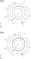
- the Figures 3 and 4 show an embodiment of a fastening element 1 according to the invention.
- the fastening element 1 designed as a torque support, has a ring 2, by means of which a sensor shaft can be enclosed.
- the fastening element 1 also has two webs 5, which each extend radially outwards from a respective connection area 6 of the ring 2 (see arrow 32) and which each have two recesses 4 at their respective ends in the circumferential direction.
- the fastening element 1 can be fastened to a housing or to a rotary encoder by means of the two second recesses 4.
- the fastening element also has two further webs 7, which each extend radially outwards from a respective further connection area 8 of the ring 2 and then in the axial direction (see symbol ⁇ , 33) and which each have a first recess 3.
- the fastening element 1 can be fastened to a rotary encoder or to a housing by means of the two first recesses 3.
- the respective connecting region 6 is arranged closer to one of the two first recesses 3 in the positive circumferential direction 30, wherein the respective web 6 extends in the negative circumferential direction 31 in the direction of the other first recess 3.
- the respective second recess 4 is arranged in the region of the end of the respective web 5 in the negative circumferential direction 31. Furthermore, the respective web 5 is essentially designed in the shape of a ring segment in the negative circumferential direction 31 outside the respective connection region.
- the respective connection region 6 is arranged offset by 40° in the positive circumferential direction 30 with respect to the center between two first recesses 3.
- the respective web 5 extends from the respective connection region 6 in the negative circumferential direction 31 over a length of 107.5° in the direction of the other first recess.
- the fastening element 1 is made of steel, in particular spring steel.
- Figure 5 shows a section of an embodiment of a machine 23 according to the invention.
- the machine 23 has a housing 22, which can be designed in several parts and can also include a cover, as in Figure 5 indicated. Furthermore, the machine 23 has a rotary encoder 21 and a fastening element by means of which the rotary encoder is attached to the housing.
- the two webs 5, the two second recesses 4 and the two first recesses 3 of the fastening element are visible, whereas other parts of the fastening element are covered by the rotary encoder 21.
- the machine also has a machine shaft 24, which is connected to a Figure 5 is non-rotatably connected to the encoder shaft (not shown).
Landscapes
- Engineering & Computer Science (AREA)
- Physics & Mathematics (AREA)
- General Physics & Mathematics (AREA)
- General Engineering & Computer Science (AREA)
- Mechanical Engineering (AREA)
- Microelectronics & Electronic Packaging (AREA)
- Power Engineering (AREA)
- Transmission And Conversion Of Sensor Element Output (AREA)
Description
- Die Erfindung betrifft ein Befestigungselement, insbesondere eine Drehmomentstütze, zur Befestigung eines Drehgebers mit einer Geberwelle an einem Gehäuse aufweisend einen Ring, mittels welchem die Geberwelle umschließbar ist, zumindest zwei erste Ausnehmungen, mittels welchen das Befestigungselement am Drehgeber bzw. am Gehäuse befestigbar ist, zumindest zwei zweite Ausnehmungen, mittels welchen das Befestigungselement am Gehäuse bzw. am Drehgeber befestigbar ist, und zumindest zwei Stege, welche sich von einem jeweiligen Verbindungsbereich des Ringes jeweils nach radial außen oder innen erstrecken und welche jeweils eine der zweiten Ausnehmungen aufweisen, wobei der jeweilige Verbindungsbereich in positiver Umfangsrichtung näher an einer von zwei benachbarten ersten Ausnehmungen angeordnet ist, wobei sich der jeweilige Steg in negativer Umfangsrichtung in Richtung der anderen der zwei benachbarten ersten Ausnehmungen erstreckt, wobei die jeweilige zweite Ausnehmung im Bereich des Endes des jeweiligen Steges in negativer Umfangsrichtung angeordnet ist, wobei das Befestigungselement weiterhin zumindest zwei weitere Stege aufweist, welche sich von einem jeweiligen weiteren Verbindungsbereich des Ringes jeweils nach radial außen oder innen erstrecken und welche jeweils eine der ersten Ausnehmungen aufweisen, wobei sich der jeweilige weitere Steg in axialer Richtung erstreckt und die jeweilige erste Ausnehmung im Bereich des axialen Endes des jeweiligen weiteren Steges angeordnet ist.
- Weiterhin betrifft die Erfindung eine Maschine, insbesondere eine elektrische Maschine, aufweisend ein Gehäuse, einen Drehgeber, ein derartiges Befestigungselement, mittels welchem der Drehgeber an dem Gehäuse befestigt ist, und eine Maschinenwelle, welche drehfest mit der Geberwelle verbunden ist.
- Ein derartiges Befestigungselement kommt beispielsweise bei Elektromotoren zum Einsatz, die mit einem Drehgeber ausgerüstet sind. Wird ein Hohlwellengeber bei Elektromotoren zur Erfassung der Drehzahl oder der Winkellage des Rotors eingesetzt, so muss das Gehäuse des Drehgebers gegenüber dem Gehäuse des Motors durch eine steife Verbindung abgestützt und am Mitdrehen gehindert werden. Ein Drehgeber (bzw. Drehwinkelgeber oder Rotary Encoder) ist dabei ein Sensor für Drehwinkel, der meist digitale Ausgangssignale liefert, die am anderen Ende der Sensorleitung im Auswertegerät decodiert werden müssen. Deshalb wird er auch als Encoder (englisch: rotary encoder) bezeichnet. "Drehgeber" kann auch als Oberbegriff für alle Winkellagegeber verwendet werden. Rundlauffehler bei der Befestigung des Gebers, Toleranzen bei der Fertigung, Wärmedehnung der Welle, sowie Schwingungen, die durch den Motor verursacht werden, führen allerdings immer wieder zu Dauerbrüchen in den vorhandenen Befestigungstechniken, was Folgeschäden verursachen kann, da die Motorüberwachung nicht mehr gewährleistet ist.
- Aus der
EP 2 216 630 A1 ist eine Drehmomentstütze zum drehsteifen Verbinden eines Drehgebers mit einer Anschlussfläche bekannt. - Aus der
EP 2 693 170 A1 ist eine Statorkupplung zur drehsteifen Verbindung zweier Bauteile bekannt, die radiale und axiale Relativbewegungen innerhalb von Toleranzgrenzen zulässt, mit einer ebenen Basisfläche, mit an der Basisfläche ansetzenden ersten Laschen, die ein Paar in einer ersten Achse (X-Achse) diametral zueinander angeordneter erster Montagepunkte zur Befestigung an dem einen Bauteil aufweisen, und mit an der Basisfläche ansetzenden und aus der Ebene der Basisfläche (10) gebogenen zweiten Laschen, die ein Paar in einer zweiten Achse (Y-Achse) diametral zueinander angeordneter zweiter Montagepunkte zur Befestigung an dem anderen Bauteil aufweisen, wobei die erste Achse (X-Achse) und die zweite Achse (Y-Achse) in der Ebene der Basisfläche etwa senkrecht zueinander verlaufen und wobei die Basisfläche jeweils zwischen den Montagepunkten geradlinige Kanten aufweist. - Aus der
US 3 987 645 A ist eine flexible Wellenkupplung bekannt, die aus einem elastisch verformbaren Kupplungselement besteht, das auf der einen Seite mit einer Antriebswelle und auf der anderen Seite mit einer angetriebenen Welle verbunden sein kann. - Eine Aufgabe der Erfindung ist es, ein Befestigungselement und eine Maschine bereitzustellen, welche insbesondere die genannten Nachteile überwinden.
- Eine Lösung der Aufgabe ergibt sich durch ein Befestigungselement der eingangs genannten Art durch die zusätzlichen Merkmale des kennzeichnenden Teils des Anspruchs 1.
- Weiterhin ergibt sich eine Lösung der Aufgabe durch eine Maschine der eingangs genannten Art dadurch, dass die Maschine das vorgeschlagene Befestigungselement aufweist.
- Die ersten Ausnehmungen und/oder die zweiten Ausnehmungen erlauben insbesondere, das Befestigungselement an dem Drehgeber bzw. an dem Gehäuse mittels Gewindestiften, Schrauben oder Bolzen zu befestigen. Dabei können die ersten Ausnehmungen und/oder die zweiten Ausnehmungen bspw. als Bohrungen ausgeführt werden. Vorzugsweise ist der Ring in axialer Richtung flach ausgebildet, insb. im Verhältnis zu seiner Erstreckung in radialer Richtung. Dabei kann der Ring bzw. das komplette Befestigungselement aus einem Blech ausgestanzt und ggf. anschließend geformt werden.
- Der Ring weist dabei Verbindungsbereiche auf, an welchen die jeweiligen Stege angeordnet sind. Bspw. sind dabei der Ring und die jeweiligen Stege einstückig ausgebildet. Der jeweilige Verbindungsbereich ist dabei nicht in der Mitte zwischen zwei benachbarten ersten Ausnehmungen angeordnet, sondern zu einer der beiden benachbarten ersten Ausnehmungen in positiver Umfangsrichtung hin verschoben. Der jeweilige Steg erstreckt sich dann in negativer Umfangsrichtung zu der anderen der beiden benachbarten ersten Ausnehmungen, d. h. zur weiter entfernten ersten Ausnehmung der beiden benachbarten ersten Ausnehmungen. Bei einer Ausgestaltung des Befestigungselementes mit zwei ersten Ausnehmungen und zwei sich nach radial außen erstreckenden Stegen kann der Ring zusammen mit den beiden Stegen dabei insbesondere die Form eines Paragraphsymbols "§" annehmen. Andere Ausgestaltungen des Befestigungselementes mit drei ersten Ausnehmungen und drei Stegen bzw. vier ersten Ausnehmungen und vier Stegen, usw., sind ebenfalls umsetzbar.
- Durch die vorgeschlagene Ausgestaltung des Befestigungselementes, insbesondere die in Umfangsrichtung verlängerte Verbindung zwischen dem Drehgeber und dem Gehäuse, werden insbesondere folgende Vorteile erzielt. So kann bspw. die Steifigkeit des Befestigungselementes in Umfangsrichtung erhöht werden, d.h. es wird eine größere Torsionssteifigkeit erreicht, was Messfehler bei Winkelmesssystemen verringert bzw. verhindert. Taumelbewegungen des Gebers, d. h. eine umlaufende Verkippung der Geberwelle, verursacht durch fehlerhaftes Ausrichten des Gebers bzw. der Geberwelle, können absorbiert werden, ohne dass dabei nennenswerte mechanische Spannungen in dem Befestigungselement verursacht werden. Dadurch kann die Lebensdauer des Befestigungselementes teils erheblich verlängert werden. Hinzu kommt, dass axiale Verschiebungen ausgeglichen werden können, welche durch Wärmeausdehnung und Fertigungstoleranzen verursacht werden. Dies wird insbesondere durch die in Umfangsrichtung verlängerte Verbindung zwischen dem Drehgeber und dem Gehäuse erreicht, die in Umfangsrichtung eine vergleichsweise hohe Steifigkeit aufweist, jedoch in axialer Richtung beweglich genug bleibt, um derartige axiale Verschiebungen auszugleichen.
- Besonders vorteilhaft ist an dem vorgeschlagenen Befestigungselement die erwähnte Verringerung der mechanischen Spannung, die im Folgenden genauer erläutert wird. Dazu wird die mechanische Spannung für das vorgeschlagene Befestigungselement und für zwei andere Befestigungselemente, die in den Figuren 1 und 2 dargestellt sind und weiter unten kurz erläutert werden, in entsprechenden Simulationen berechnet, wobei die jeweiligen Befestigungselemente verschiedenen Lasten ausgesetzt werden. Die Lasten entsprechen dabei einer axialen Verschiebung, wobei bei den Simulationen ein Wert von 2 mm angenommen wird. Dies spiegelt eine Wärmedehnung einer Welle, bspw. einer Rotorwelle einer als Elektromotor ausgestalteten Maschine wider. Weiterhin berücksichtigen die Lasten eine umlaufende Verkippung bzw. Verdrehung, welche in Richtung der Hochachse und der Querachse variiert wird. Dies spiegelt eine fehlerhafte Ausrichtung der Geberwelle wider. Bei dem Befestigungselement gemäß der
Figur 2 werden dabei zwei mögliche Ausrichtung innerhalb der Langlöcher berücksichtigt. - Die Ergebnisse der Simulationen sind in der Tabelle unten zusammengestellt, wobei die Ergebnisse für die verschiedenen Befestigungselemente wie folgt benannt sind:
"A": das Befestigungselement gemäßFigur 1 ,
"B1" bzw. "B2": das Befestigungselement gemäßFigur 2 mit einer ersten bzw. zweiten Ausrichtung innerhalb der Langlöcher
"C": ein Ausführungsbeispiel des vorgeschlagenen Befestigungselements gemäß denFiguren 3 und 4 .Verdrehung (in °) Vergleichsspannungen (in MPa) Hochachse Querachse "A" "B1" "B2" "C" -5 -5 1335 1192 1519 291 0 -5 1152 1399 1263 204 5 -5 1275 1742 1540 217 -5 0 835 734 946 172 0 0 619 599 665 86 5 0 832 744 940 172 -5 5 1283 1748 1542 216 0 5 1148 1401 1262 205 5 5 1349 1204 1520 293 Maximum 1349 1748 293 - Durch das vorgeschlagene Befestigungselement können die üblicherweise während des Betriebs auftretenden mechanischen Spannungen im Vergleich zu den beiden Befestigungselementen gemäß den
Figuren 1 und 2 somit beträchtlich verringert werden: bei dem Ausführungsbeispiel gemäß denFiguren 3 und 4 sogar um beachtliche 78% bzw. 83%. Aber auch andere Ausgestaltungen des vorgeschlagenen Befestigungselementes bewirken eine deutliche Verringerung der während des Betriebs auftretenden mechanischen Spannungen. Dies geht unter anderem einher mit einer deutlich verlängerten Lebensdauer des vorgeschlagenen Befestigungselementes. - Die jeweilige zweite Ausnehmung ist im Bereich des Endes des jeweiligen Steges in negativer Umfangsrichtung angeordnet. Dadurch kann die Länge des jeweiligen Steges in Umfangsrichtung besonders gut ausgenutzt werden gleichzeitig Material eingespart werden. Weiterhin weist das vorgeschlagene Befestigungselement dadurch eine besonders große Torsionssteifigkeit auf.
- Das Befestigungselement weist zumindest zwei weitere Stege auf, welche sich von einem jeweiligen weiteren Verbindungsbereich des Ringes jeweils nach radial außen oder innen erstrecken und welche jeweils eine der ersten Ausnehmungen aufweisen.
- Der jeweilige weitere Steg erstreckt sich dabei in axialer Richtung, insbesondere zum Drehgeber bzw. zum Gehäuse bzw. in jener axialen Richtung, in welcher der Drehgeber bzw. das Gehäuse relativ zum Befestigungselement positioniert werden kann, um das Befestigungselement über die jeweilige erste Ausnehmung am Drehgeber bzw. am Gehäuse zu befestigen, wobei die jeweilige erste Ausnehmung im Bereich des axialen Endes des jeweiligen weiteren Steges angeordnet ist. Beispielsweise weist das Befestigungselement zwei erste Ausnehmungen, zwei zweite Ausnehmungen und zwei Stege auf, die sich jeweils paarweise diametral gegenüberliegen.
- Bei einer vorteilhaften Ausgestaltung der Erfindung ist der jeweilige Steg in negativer Umfangsrichtung außerhalb des jeweiligen Verbindungsbereichs im Wesentlichen ringsegmentförmig ausgestaltet. Je nach seiner Erstreckung in Umfangsrichtung, bspw. eine Viertel Umdrehung bzw. 90°, weist der jeweilige Steg somit die Gestalt eines entsprechenden Teils eines vollständigen Ringes auf, bspw. ein Viertel eines vollständigen Ringes. Auch dadurch kann die Torsionssteifigkeit des vorgeschlagenen Befestigungselementes erhöht werden und somit eine besonders langlebige Ausgestaltung des vorgeschlagenen Befestigungselementes erzielt werden.
- Bei einer weiteren vorteilhaften Ausgestaltung der Erfindung erstreckt sich der jeweilige Steg in negativer Umfangsrichtung bis zu der anderen der zwei benachbarten ersten Ausnehmungen oder über die andere der zwei benachbarten ersten Ausnehmungen hinaus. Diese beiden Ausgestaltungen ermöglichen eine besonders große Torsionssteifigkeit des vorgeschlagenen Befestigungselementes.
- Bei der Erfindung weist das Befestigungselement zwei erste Ausnehmungen, zwei zweite Ausnehmungen und zwei Stege auf, die sich jeweils paarweise diametral gegenüberliegen, wobei der jeweilige Verbindungsbereich in positiver Umfangsrichtung um 30° bis 50°, vorzugsweise 40°, gegenüber der Mitte zwischen zwei benachbarten ersten Ausnehmungen versetzt angeordnet ist, und wobei sich der jeweilige Steg ausgehend von dem jeweiligen Verbindungsbereich in negativer Umfangsrichtung auf einer Länge von 100° bis 120°, vorzugsweise 107,5° in Richtung der anderen der zwei benachbarten ersten Ausnehmungen erstreckt.
- Diese Ausgestaltung des Befestigungselementes ermöglicht dessen Fertigung aus einem Stück, bspw. einem Blech, insbesondere, wenn weitere Stege für die ersten Ausnehmungen vorgesehen sind und sich diese weiteren Stege in dieselbe radiale Richtung wie die Stege für die zweiten Ausnehmungen erstrecken. Das Befestigungselement kann zum Beispiel durch Stanzen oder Lasern aus einem Stück hergestellt werden. Dank der erläuterten des jeweiligen Steges können dabei die erläuterte hohe Torsionssteifigkeit sowie die Toleranz gegenüber axialen Verschiebungen erreicht werden.
- Bei einer weiteren vorteilhaften Ausgestaltung der Erfindung ist zumindest der jeweilige Steg, insb. das ganze Befestigungselement aus Stahl, insb. Federstahl. Dies erlaubt eine robuste Ausführung des Befestigungselementes und dies wiederum eine hohe Kundenakzeptanz.
- Bei einer weiteren vorteilhaften Ausgestaltung der Erfindung umfasst die Maschine einen Elektromotor oder einen Elektrogenerator. Zusätzlich kann die Maschine bspw. ein Getriebe und/oder andere Teile einer größeren Anlage umfassen.
- Oftmals werden besonders gute Ergebnisse erzielt, wenn sich die Stege und ggf. die weiteren Stege vom Ring nach radial außen erstrecken.
- Im Folgenden wird die Erfindung anhand der in den Figuren dargestellten Ausführungsbeispiele näher beschrieben und erläutert. Es zeigen:
- FIG 1
- eine erste Drehmomentstütze,
- FIG 2
- eine zweite Drehmomentstütze,
- FIGs 3&4
- ein Ausführungsbeispiel eines erfindungsgemäßen Befestigungselementes, und
- FIG 5
- einen Ausschnitt eines Ausführungsbeispiels einer erfindungsgemäßen Maschine.
-
Figur 1 zeigt eine erste Drehmomentstütze. Die Drehmomentstütze weist einen Ring 2 auf, durch welchen eine Geberwelle hindurchgeführt werden kann. Weiterhin weist die Drehmomentstütze zwei Stege 5 mit jeweils einer zweiten Ausnehmung 4 sowie zwei weitere Stege 7 mit jeweils zwei ersten Ausnehmungen 3 auf. Dabei sind die Paare von Stegen und weiteren Stegen in Umfangsrichtung um 90° zueinander versetzt angeordnet. Mithilfe der ersten Ausnehmungen 3 kann die Drehmomentstütze 1 an einem Drehgeber befestigt werden und mithilfe der zweiten Ausnehmungen 4 an einem Gehäuse einer Maschine. -
Figur 2 zeigt eine zweite Drehmomentstütze mit einer gegenüber der inFigur 1 dargestellten ersten Drehmomentstütze modifizierten Geometrie. Dabei bezeichnen gleiche Bezugszeichen wie inFigur 1 gleiche Gegenstände. - Die
Figuren 3 und 4 zeigen ein Ausführungsbeispiel eines erfindungsgemäßen Befestigungselementes 1. Das als Drehmomentstütze ausgeführte Befestigungselement 1 weist einen Ring 2 auf, mittels welchem eine Geberwelle umschließbar ist. Weiterhin weist das Befestigungselement 1 zwei Stege 5 auf, welche sich von einem jeweiligen Verbindungsbereich 6 des Ringes 2 jeweils nach radial außen (vgl. Pfeil 32) erstrecken und welche an ihrem jeweiligen Ende in Umfangsrichtung jeweils zwei Ausnehmungen 4 aufweisen. Mittels der beiden zweiten Ausnehmungen 4 ist das Befestigungselement 1 an einem Gehäuse bzw. an einem Drehgeber befestigbar. Das Befestigungselement weist weiterhin zwei weitere Stege 7 auf, welche sich von einem jeweiligen weiteren Verbindungsbereich 8 des Ringes 2 jeweils zunächst nach radial außen und anschließend sich in axiale Richtung (vgl. Symbol ⊗, 33) erstrecken und welche jeweils eine erste Ausnehmung 3 aufweisen. Mittels der beiden ersten Ausnehmungen 3 ist das Befestigungselement 1 an einem Drehgeber bzw. an einem Gehäuse befestigbar. - Wie in den
Figuren 3 und 4 dargestellt, ist der jeweilige Verbindungsbereich 6 in positiver Umfangsrichtung 30 näher an einer der beiden ersten Ausnehmungen 3 angeordnet, wobei sich der jeweilige Steg 6 in negativer Umfangsrichtung 31 in Richtung der anderen ersten Ausnehmung 3 erstreckt. - Die jeweilige zweite Ausnehmung 4 ist dabei im Bereich des Endes des jeweiligen Steges 5 in negativer Umfangsrichtung 31 angeordnet. Weiterhin ist der jeweilige Steg 5 in negativer Umfangsrichtung 31 außerhalb des jeweiligen Verbindungsbereiches im Wesentlichen ringsegmentförmig ausgestaltet. Der jeweilige Verbindungsbereich 6 ist dabei in positiver Umfangsrichtung 30 um 40° gegenüber der Mitte zwischen zwei ersten Ausnehmungen 3 versetzt angeordnet. Dabei erstreckt sich der jeweilige Steg 5 ausgehend von dem jeweiligen Verbindungsbereich 6 in negativer Umfangsrichtung 31 auf einer Länge von 107,5° in Richtung der anderen ersten Ausnehmung.
- Vorzugsweise ist das Befestigungselement 1 dabei aus Stahl, insbesondere Federstahl gefertigt.
-
Figur 5 zeigt einen Ausschnitt eines Ausführungsbeispiels einer erfindungsgemäßen Maschine 23. Die Maschine 23 weist ein Gehäuse 22 auf, welches mehrstückig ausgebildet sein kann und dabei auch einen Deckel umfassen kann, wie inFigur 5 angedeutet. Weiterhin weist die Maschine 23 einen Drehgeber 21 und ein Befestigungselement auf, mittels welchem der Drehgeber an dem Gehäuse befestigt ist. InFigur 5 sind von dem Befestigungselement die zwei Stege 5, die zwei zweiten Ausnehmungen 4 sowie die zwei ersten Ausnehmungen 3 erkennbar, wohingegen andere Teile des Befestigungselementes von dem Drehgeber 21 verdeckt sind. Die Maschine weist weiterhin eine Maschinenwelle 24 auf, welche mit einer inFigur 5 nicht dargestellten Geberwelle drehfest verbunden ist.
Claims (7)
- Befestigungselement (1), insbesondere Drehmomentstütze, zur Befestigung eines Drehgebers (21) mit einer Geberwelle an einem Gehäuse (22) aufweisend- einen Ring (2), mittels welchem die Geberwelle umschließbar ist,- zumindest zwei erste Ausnehmungen (3), mittels welchen das Befestigungselement (1) am Drehgeber (21) bzw. am Gehäuse (22) befestigbar ist,- zumindest zwei zweite Ausnehmungen (4), mittels welchen das Befestigungselement (1) am Gehäuse (22) bzw. am Drehgeber (21) befestigbar ist,- zumindest zwei Stege (5), welche sich von einem jeweiligen Verbindungsbereich (6) des Ringes (2) jeweils nach radial außen oder innen erstrecken und welche jeweils eine der zweiten Ausnehmungen (4) aufweisen,- wobei der jeweilige Verbindungsbereich (6) in positiver Umfangsrichtung (30) näher an einer von zwei benachbarten ersten Ausnehmungen (3) angeordnet ist,- wobei sich der jeweilige Steg (6) in negativer Umfangsrichtung (31) in Richtung der anderen der zwei benachbarten ersten Ausnehmungen (3) erstreckt,wobei die jeweilige zweite Ausnehmung (4) im Bereich des Endes des jeweiligen Steges (5) in negativer Umfangsrichtung (31) angeordnet ist,wobei das Befestigungselement (1) weiterhin zumindest zwei weitere Stege (7) aufweist, welche sich von einem jeweiligen weiteren Verbindungsbereich (8) des Ringes (2) jeweils nach radial außen oder innen erstrecken und welche jeweils eine der ersten Ausnehmungen (3) aufweisen,wobei sich der jeweilige weitere Steg (7) in axialer Richtung erstreckt und die jeweilige erste Ausnehmung (3) im Bereich des axialen Endes des jeweiligen weiteren Steges (7) angeordnet ist,dadurch gekennzeichnet, dassdas Befestigungselement (1) zwei erste Ausnehmungen (3), zwei zweite Ausnehmungen (4) und zwei Stege (5) aufweist, die sich jeweils paarweise diametral gegenüberliegen,wobei der jeweilige Verbindungsbereich (6) in positiver Umfangsrichtung (30) um 30° bis 50°, vorzugsweise 40°, gegenüber der Mitte zwischen zwei benachbarten ersten Ausnehmungen (3) versetzt angeordnet ist, undwobei sich der jeweilige Steg (5) ausgehend von dem jeweiligen Verbindungsbereich (6) in negativer Umfangsrichtung (31) auf einer Länge von 100° bis 120° erstreckt.
- Befestigungselement (1) nach Anspruch 1,
wobei der jeweilige Steg (5) in negativer Umfangsrichtung (31) außerhalb des jeweiligen Verbindungsbereichs (6) im Wesentlichen ringsegmentförmig ausgestaltet ist. - Befestigungselement (1) nach einem der vorherigen Ansprüche,
wobei sich der jeweilige Steg (5) in negativer Umfangsrichtung (31) bis zu der anderen der zwei benachbarten ersten Ausnehmungen (3) oder über die andere der zwei benachbarten ersten Ausnehmungen (3) hinaus erstreckt. - Befestigungselement (1) nach einem der vorherigen Ansprüche,
wobei sich der jeweilige Steg (5) ausgehend von dem jeweiligen Verbindungsbereich (6) in negativer Umfangsrichtung (31) auf einer Länge von 107,5° in Richtung der anderen der zwei benachbarten ersten Ausnehmungen (3) erstreckt. - Befestigungselement (1) nach einem der vorherigen Ansprüche,
wobei zumindest der jeweilige Steg (5), insb. das ganze Befestigungselement (1) aus Stahl, insb. Federstahl, ist. - Maschine (23), insbesondere elektrische Maschine, aufweisend- ein Gehäuse (22),- einen Drehgeber (21),- ein Befestigungselement (1) nach einem der vorherigen Ansprüche, mittels welchem der Drehgeber (21) an dem Gehäuse (22) befestigt ist, und- eine Maschinenwelle (24), welche drehfest mit der Geberwelle verbunden ist.
- Maschine (23) nach Anspruch 6, wobei die Maschine (23) einen Elektromotor oder einen Elektrogenerator umfasst.
Applications Claiming Priority (2)
| Application Number | Priority Date | Filing Date | Title |
|---|---|---|---|
| EP20187922.8A EP3945291A1 (de) | 2020-07-27 | 2020-07-27 | Befestigungselement, insbesondere drehmomentstütze, und maschine |
| PCT/EP2021/064733 WO2022022877A1 (de) | 2020-07-27 | 2021-06-02 | Befestigungselement, insbesondere drehmomentstütze, und maschine |
Publications (2)
| Publication Number | Publication Date |
|---|---|
| EP4153948A1 EP4153948A1 (de) | 2023-03-29 |
| EP4153948B1 true EP4153948B1 (de) | 2024-07-24 |
Family
ID=71833242
Family Applications (2)
| Application Number | Title | Priority Date | Filing Date |
|---|---|---|---|
| EP20187922.8A Withdrawn EP3945291A1 (de) | 2020-07-27 | 2020-07-27 | Befestigungselement, insbesondere drehmomentstütze, und maschine |
| EP21731715.5A Active EP4153948B1 (de) | 2020-07-27 | 2021-06-02 | Befestigungselement, insbesondere drehmomentstütze, und maschine |
Family Applications Before (1)
| Application Number | Title | Priority Date | Filing Date |
|---|---|---|---|
| EP20187922.8A Withdrawn EP3945291A1 (de) | 2020-07-27 | 2020-07-27 | Befestigungselement, insbesondere drehmomentstütze, und maschine |
Country Status (3)
| Country | Link |
|---|---|
| EP (2) | EP3945291A1 (de) |
| CN (1) | CN116209880B (de) |
| WO (1) | WO2022022877A1 (de) |
Families Citing this family (2)
| Publication number | Priority date | Publication date | Assignee | Title |
|---|---|---|---|---|
| CN114762226B (zh) * | 2019-12-04 | 2025-10-10 | 索尤若驱动有限及两合公司 | 有风机罩、转子轴和角度传感器的电机 |
| WO2025131499A1 (de) * | 2023-12-22 | 2025-06-26 | Sew-Eurodrive Gmbh & Co Kg | Elektromotor mit ersten winkelsensor |
Family Cites Families (11)
| Publication number | Priority date | Publication date | Assignee | Title |
|---|---|---|---|---|
| NL7400886A (nl) * | 1974-01-23 | 1975-07-25 | Philips Nv | Flexibele askoppeling. |
| DE29911508U1 (de) * | 1999-07-01 | 2000-12-07 | Dr. Johannes Heidenhain Gmbh, 83301 Traunreut | Kupplung und Verwendung dieser Kupplung in einer Winkelmeßeinrichtung |
| DE10203278B4 (de) * | 2001-03-09 | 2012-11-22 | Dr. Johannes Heidenhain Gmbh | Kupplung und Winkelmessvorrichtung mit einer derartigen Kupplung |
| DE102006020067A1 (de) * | 2005-06-11 | 2006-12-14 | Dr. Johannes Heidenhain Gmbh | Kupplung und Winkelmesseinrichtung mit dieser Kupplung |
| DE102008032419A1 (de) * | 2008-07-10 | 2010-01-14 | Dr. Johannes Heidenhain Gmbh | Drehgeber und Baureihe von Drehgebern |
| EP2216630B2 (de) | 2008-11-24 | 2015-09-30 | Pepperl + Fuchs Drehgeber GmbH | Drehmomentstütze |
| CN101793534B (zh) * | 2010-01-22 | 2012-01-25 | 中国船舶重工集团公司第七一七研究所 | 一种内环直立式四轴稳定平台 |
| DE202011107029U1 (de) * | 2011-10-17 | 2013-01-18 | Fritz Kübler GmbH Zähl- und Sensortechnik | Drehgebersystem mit Drehgeber und Anschlussstück |
| EP2693170B1 (de) * | 2012-07-31 | 2014-09-24 | SICK STEGMANN GmbH | Statorkupplung |
| EP3301405A1 (de) * | 2016-09-29 | 2018-04-04 | Siemens Aktiengesellschaft | Verbinden einer motorwelle eines motors mit einem drehgeber |
| EP3372858A1 (de) * | 2017-03-07 | 2018-09-12 | Siemens Aktiengesellschaft | Kupplungselemente mit schwingungsdämpfung |
-
2020
- 2020-07-27 EP EP20187922.8A patent/EP3945291A1/de not_active Withdrawn
-
2021
- 2021-06-02 WO PCT/EP2021/064733 patent/WO2022022877A1/de not_active Ceased
- 2021-06-02 EP EP21731715.5A patent/EP4153948B1/de active Active
- 2021-06-02 CN CN202180059720.3A patent/CN116209880B/zh active Active
Also Published As
| Publication number | Publication date |
|---|---|
| EP3945291A1 (de) | 2022-02-02 |
| WO2022022877A1 (de) | 2022-02-03 |
| CN116209880B (zh) | 2024-06-18 |
| EP4153948A1 (de) | 2023-03-29 |
| CN116209880A (zh) | 2023-06-02 |
Similar Documents
| Publication | Publication Date | Title |
|---|---|---|
| DE3785931T2 (de) | Elastische kupplung. | |
| DE102016219919A1 (de) | Elastisches Zahnrad eines Wellgetriebes | |
| EP1722459B1 (de) | Elektrische Maschine mit Abstützung des Rotors auf einer Stirnseite des Stators | |
| EP2960530A1 (de) | Montageverfahren für eine elektrische Maschine mit zumindest zwei Maschinensegmenten | |
| DE102004036644B4 (de) | Motor für Waschmaschine | |
| EP1722460B1 (de) | Elektrische Maschine mit vorgespanntem Kugellager und Verfahren zur Herstellung derselben | |
| DE8915109U1 (de) | Kupplung | |
| EP3945291A1 (de) | Befestigungselement, insbesondere drehmomentstütze, und maschine | |
| EP1178232B1 (de) | Flanschmitnehmer für ein Kardangelenk und Gelenkwelle | |
| WO2002053917A1 (de) | Kältemittelverdichter | |
| DE3689054T2 (de) | Rotorzusammenbau für Roots-Pumpe. | |
| DE102015001447B4 (de) | Elektromotor mit einem Entkopplungsring | |
| EP2189675B1 (de) | Wellenkupplung | |
| DE3109388A1 (de) | "hochelastische wellenkupplung" | |
| EP3771841B1 (de) | Lagerschale für ein kugelgelenk sowie kugelgelenk | |
| DE10127653A1 (de) | Antriebwelle | |
| DE102020122909B4 (de) | Klappergeräusch reduzierende säulenbaugruppe für elektrische servolenkung und verfahren | |
| DE69517779T2 (de) | Elastische Kupplung für drehende Wellen | |
| DE102013211476A1 (de) | Loslagersystem für eine elektrische Maschine | |
| DE19750920A1 (de) | Getriebekopfanordnung und Verfahren zur Montage derselben an einen Motor | |
| DE202004003695U1 (de) | Hydrodynamisches Lagersystem zur Drehlagerung eines Spindelmotors | |
| DE2801617C3 (de) | Lagerzentrierung von geteilten Pleuelstangen | |
| WO2013163995A2 (de) | Selbstfixierendes statorgehäuse | |
| WO2023102587A1 (de) | Rotor | |
| EP2424083B1 (de) | Elektromotor und Verfahren zu dessen Herstellung |
Legal Events
| Date | Code | Title | Description |
|---|---|---|---|
| STAA | Information on the status of an ep patent application or granted ep patent |
Free format text: STATUS: UNKNOWN |
|
| STAA | Information on the status of an ep patent application or granted ep patent |
Free format text: STATUS: THE INTERNATIONAL PUBLICATION HAS BEEN MADE |
|
| PUAI | Public reference made under article 153(3) epc to a published international application that has entered the european phase |
Free format text: ORIGINAL CODE: 0009012 |
|
| STAA | Information on the status of an ep patent application or granted ep patent |
Free format text: STATUS: REQUEST FOR EXAMINATION WAS MADE |
|
| 17P | Request for examination filed |
Effective date: 20221222 |
|
| AK | Designated contracting states |
Kind code of ref document: A1 Designated state(s): AL AT BE BG CH CY CZ DE DK EE ES FI FR GB GR HR HU IE IS IT LI LT LU LV MC MK MT NL NO PL PT RO RS SE SI SK SM TR |
|
| DAV | Request for validation of the european patent (deleted) | ||
| DAX | Request for extension of the european patent (deleted) | ||
| RAP1 | Party data changed (applicant data changed or rights of an application transferred) |
Owner name: INNOMOTICS GMBH |
|
| GRAP | Despatch of communication of intention to grant a patent |
Free format text: ORIGINAL CODE: EPIDOSNIGR1 |
|
| STAA | Information on the status of an ep patent application or granted ep patent |
Free format text: STATUS: GRANT OF PATENT IS INTENDED |
|
| INTG | Intention to grant announced |
Effective date: 20240118 |
|
| GRAS | Grant fee paid |
Free format text: ORIGINAL CODE: EPIDOSNIGR3 |
|
| GRAA | (expected) grant |
Free format text: ORIGINAL CODE: 0009210 |
|
| STAA | Information on the status of an ep patent application or granted ep patent |
Free format text: STATUS: THE PATENT HAS BEEN GRANTED |
|
| AK | Designated contracting states |
Kind code of ref document: B1 Designated state(s): AL AT BE BG CH CY CZ DE DK EE ES FI FR GB GR HR HU IE IS IT LI LT LU LV MC MK MT NL NO PL PT RO RS SE SI SK SM TR |
|
| REG | Reference to a national code |
Ref country code: GB Ref legal event code: FG4D Free format text: NOT ENGLISH |
|
| REG | Reference to a national code |
Ref country code: CH Ref legal event code: EP |
|
| REG | Reference to a national code |
Ref country code: IE Ref legal event code: FG4D Free format text: LANGUAGE OF EP DOCUMENT: GERMAN Ref country code: DE Ref legal event code: R096 Ref document number: 502021004498 Country of ref document: DE |
|
| REG | Reference to a national code |
Ref country code: DE Ref legal event code: R081 Ref document number: 502021004498 Country of ref document: DE Owner name: INNOMOTICS GMBH, DE Free format text: FORMER OWNER: ANMELDERANGABEN UNKLAR / UNVOLLSTAENDIG, 80297 MUENCHEN, DE Ref country code: DE Ref legal event code: R081 Ref document number: 502021004498 Country of ref document: DE Owner name: ANMELDERANGABEN UNKLAR / UNVOLLSTAENDIG, DE Free format text: FORMER OWNER: ANMELDERANGABEN UNKLAR / UNVOLLSTAENDIG, 80297 MUENCHEN, DE |
|
| REG | Reference to a national code |
Ref country code: DE Ref legal event code: R081 Ref document number: 502021004498 Country of ref document: DE Owner name: INNOMOTICS GMBH, DE Free format text: FORMER OWNER: INNOMOTICS GMBH, MUENCHEN, DE Ref country code: DE Ref legal event code: R081 Ref document number: 502021004498 Country of ref document: DE Owner name: ANMELDERANGABEN UNKLAR / UNVOLLSTAENDIG, DE Free format text: FORMER OWNER: INNOMOTICS GMBH, MUENCHEN, DE |
|
| REG | Reference to a national code |
Ref country code: LT Ref legal event code: MG9D |
|
| REG | Reference to a national code |
Ref country code: NL Ref legal event code: MP Effective date: 20240724 |
|
| PG25 | Lapsed in a contracting state [announced via postgrant information from national office to epo] |
Ref country code: PT Free format text: LAPSE BECAUSE OF FAILURE TO SUBMIT A TRANSLATION OF THE DESCRIPTION OR TO PAY THE FEE WITHIN THE PRESCRIBED TIME-LIMIT Effective date: 20241125 |
|
| PG25 | Lapsed in a contracting state [announced via postgrant information from national office to epo] |
Ref country code: NL Free format text: LAPSE BECAUSE OF FAILURE TO SUBMIT A TRANSLATION OF THE DESCRIPTION OR TO PAY THE FEE WITHIN THE PRESCRIBED TIME-LIMIT Effective date: 20240724 |
|
| PG25 | Lapsed in a contracting state [announced via postgrant information from national office to epo] |
Ref country code: PT Free format text: LAPSE BECAUSE OF FAILURE TO SUBMIT A TRANSLATION OF THE DESCRIPTION OR TO PAY THE FEE WITHIN THE PRESCRIBED TIME-LIMIT Effective date: 20241125 Ref country code: NL Free format text: LAPSE BECAUSE OF FAILURE TO SUBMIT A TRANSLATION OF THE DESCRIPTION OR TO PAY THE FEE WITHIN THE PRESCRIBED TIME-LIMIT Effective date: 20240724 |
|
| PG25 | Lapsed in a contracting state [announced via postgrant information from national office to epo] |
Ref country code: NO Free format text: LAPSE BECAUSE OF FAILURE TO SUBMIT A TRANSLATION OF THE DESCRIPTION OR TO PAY THE FEE WITHIN THE PRESCRIBED TIME-LIMIT Effective date: 20241024 |
|
| PG25 | Lapsed in a contracting state [announced via postgrant information from national office to epo] |
Ref country code: PL Free format text: LAPSE BECAUSE OF FAILURE TO SUBMIT A TRANSLATION OF THE DESCRIPTION OR TO PAY THE FEE WITHIN THE PRESCRIBED TIME-LIMIT Effective date: 20240724 Ref country code: FI Free format text: LAPSE BECAUSE OF FAILURE TO SUBMIT A TRANSLATION OF THE DESCRIPTION OR TO PAY THE FEE WITHIN THE PRESCRIBED TIME-LIMIT Effective date: 20240724 Ref country code: GR Free format text: LAPSE BECAUSE OF FAILURE TO SUBMIT A TRANSLATION OF THE DESCRIPTION OR TO PAY THE FEE WITHIN THE PRESCRIBED TIME-LIMIT Effective date: 20241025 |
|
| PG25 | Lapsed in a contracting state [announced via postgrant information from national office to epo] |
Ref country code: BG Free format text: LAPSE BECAUSE OF FAILURE TO SUBMIT A TRANSLATION OF THE DESCRIPTION OR TO PAY THE FEE WITHIN THE PRESCRIBED TIME-LIMIT Effective date: 20240724 |
|
| PG25 | Lapsed in a contracting state [announced via postgrant information from national office to epo] |
Ref country code: LV Free format text: LAPSE BECAUSE OF FAILURE TO SUBMIT A TRANSLATION OF THE DESCRIPTION OR TO PAY THE FEE WITHIN THE PRESCRIBED TIME-LIMIT Effective date: 20240724 |
|
| PG25 | Lapsed in a contracting state [announced via postgrant information from national office to epo] |
Ref country code: IS Free format text: LAPSE BECAUSE OF FAILURE TO SUBMIT A TRANSLATION OF THE DESCRIPTION OR TO PAY THE FEE WITHIN THE PRESCRIBED TIME-LIMIT Effective date: 20241124 |
|
| PG25 | Lapsed in a contracting state [announced via postgrant information from national office to epo] |
Ref country code: HR Free format text: LAPSE BECAUSE OF FAILURE TO SUBMIT A TRANSLATION OF THE DESCRIPTION OR TO PAY THE FEE WITHIN THE PRESCRIBED TIME-LIMIT Effective date: 20240724 |
|
| PG25 | Lapsed in a contracting state [announced via postgrant information from national office to epo] |
Ref country code: RS Free format text: LAPSE BECAUSE OF FAILURE TO SUBMIT A TRANSLATION OF THE DESCRIPTION OR TO PAY THE FEE WITHIN THE PRESCRIBED TIME-LIMIT Effective date: 20241024 Ref country code: ES Free format text: LAPSE BECAUSE OF FAILURE TO SUBMIT A TRANSLATION OF THE DESCRIPTION OR TO PAY THE FEE WITHIN THE PRESCRIBED TIME-LIMIT Effective date: 20240724 |
|
| PG25 | Lapsed in a contracting state [announced via postgrant information from national office to epo] |
Ref country code: RS Free format text: LAPSE BECAUSE OF FAILURE TO SUBMIT A TRANSLATION OF THE DESCRIPTION OR TO PAY THE FEE WITHIN THE PRESCRIBED TIME-LIMIT Effective date: 20241024 Ref country code: PL Free format text: LAPSE BECAUSE OF FAILURE TO SUBMIT A TRANSLATION OF THE DESCRIPTION OR TO PAY THE FEE WITHIN THE PRESCRIBED TIME-LIMIT Effective date: 20240724 Ref country code: NO Free format text: LAPSE BECAUSE OF FAILURE TO SUBMIT A TRANSLATION OF THE DESCRIPTION OR TO PAY THE FEE WITHIN THE PRESCRIBED TIME-LIMIT Effective date: 20241024 Ref country code: LV Free format text: LAPSE BECAUSE OF FAILURE TO SUBMIT A TRANSLATION OF THE DESCRIPTION OR TO PAY THE FEE WITHIN THE PRESCRIBED TIME-LIMIT Effective date: 20240724 Ref country code: IS Free format text: LAPSE BECAUSE OF FAILURE TO SUBMIT A TRANSLATION OF THE DESCRIPTION OR TO PAY THE FEE WITHIN THE PRESCRIBED TIME-LIMIT Effective date: 20241124 Ref country code: HR Free format text: LAPSE BECAUSE OF FAILURE TO SUBMIT A TRANSLATION OF THE DESCRIPTION OR TO PAY THE FEE WITHIN THE PRESCRIBED TIME-LIMIT Effective date: 20240724 Ref country code: GR Free format text: LAPSE BECAUSE OF FAILURE TO SUBMIT A TRANSLATION OF THE DESCRIPTION OR TO PAY THE FEE WITHIN THE PRESCRIBED TIME-LIMIT Effective date: 20241025 Ref country code: FI Free format text: LAPSE BECAUSE OF FAILURE TO SUBMIT A TRANSLATION OF THE DESCRIPTION OR TO PAY THE FEE WITHIN THE PRESCRIBED TIME-LIMIT Effective date: 20240724 Ref country code: ES Free format text: LAPSE BECAUSE OF FAILURE TO SUBMIT A TRANSLATION OF THE DESCRIPTION OR TO PAY THE FEE WITHIN THE PRESCRIBED TIME-LIMIT Effective date: 20240724 Ref country code: BG Free format text: LAPSE BECAUSE OF FAILURE TO SUBMIT A TRANSLATION OF THE DESCRIPTION OR TO PAY THE FEE WITHIN THE PRESCRIBED TIME-LIMIT Effective date: 20240724 |
|
| REG | Reference to a national code |
Ref country code: DE Ref legal event code: R081 Ref document number: 502021004498 Country of ref document: DE Owner name: INNOMOTICS GMBH, DE Free format text: FORMER OWNER: ANMELDERANGABEN UNKLAR / UNVOLLSTAENDIG, 80297 MUENCHEN, DE |
|
| PG25 | Lapsed in a contracting state [announced via postgrant information from national office to epo] |
Ref country code: SM Free format text: LAPSE BECAUSE OF FAILURE TO SUBMIT A TRANSLATION OF THE DESCRIPTION OR TO PAY THE FEE WITHIN THE PRESCRIBED TIME-LIMIT Effective date: 20240724 Ref country code: DK Free format text: LAPSE BECAUSE OF FAILURE TO SUBMIT A TRANSLATION OF THE DESCRIPTION OR TO PAY THE FEE WITHIN THE PRESCRIBED TIME-LIMIT Effective date: 20240724 Ref country code: RO Free format text: LAPSE BECAUSE OF FAILURE TO SUBMIT A TRANSLATION OF THE DESCRIPTION OR TO PAY THE FEE WITHIN THE PRESCRIBED TIME-LIMIT Effective date: 20240724 |
|
| PG25 | Lapsed in a contracting state [announced via postgrant information from national office to epo] |
Ref country code: EE Free format text: LAPSE BECAUSE OF FAILURE TO SUBMIT A TRANSLATION OF THE DESCRIPTION OR TO PAY THE FEE WITHIN THE PRESCRIBED TIME-LIMIT Effective date: 20240724 |
|
| PG25 | Lapsed in a contracting state [announced via postgrant information from national office to epo] |
Ref country code: CZ Free format text: LAPSE BECAUSE OF FAILURE TO SUBMIT A TRANSLATION OF THE DESCRIPTION OR TO PAY THE FEE WITHIN THE PRESCRIBED TIME-LIMIT Effective date: 20240724 |
|
| REG | Reference to a national code |
Ref country code: DE Ref legal event code: R097 Ref document number: 502021004498 Country of ref document: DE |
|
| PG25 | Lapsed in a contracting state [announced via postgrant information from national office to epo] |
Ref country code: SK Free format text: LAPSE BECAUSE OF FAILURE TO SUBMIT A TRANSLATION OF THE DESCRIPTION OR TO PAY THE FEE WITHIN THE PRESCRIBED TIME-LIMIT Effective date: 20240724 |
|
| PLBE | No opposition filed within time limit |
Free format text: ORIGINAL CODE: 0009261 |
|
| STAA | Information on the status of an ep patent application or granted ep patent |
Free format text: STATUS: NO OPPOSITION FILED WITHIN TIME LIMIT |
|
| 26N | No opposition filed |
Effective date: 20250425 |
|
| PGFP | Annual fee paid to national office [announced via postgrant information from national office to epo] |
Ref country code: DE Payment date: 20250625 Year of fee payment: 5 |
|
| PGFP | Annual fee paid to national office [announced via postgrant information from national office to epo] |
Ref country code: AT Payment date: 20250721 Year of fee payment: 5 |
|
| PG25 | Lapsed in a contracting state [announced via postgrant information from national office to epo] |
Ref country code: SE Free format text: LAPSE BECAUSE OF FAILURE TO SUBMIT A TRANSLATION OF THE DESCRIPTION OR TO PAY THE FEE WITHIN THE PRESCRIBED TIME-LIMIT Effective date: 20240724 |
|
| PGFP | Annual fee paid to national office [announced via postgrant information from national office to epo] |
Ref country code: IT Payment date: 20250624 Year of fee payment: 5 |
|
| REG | Reference to a national code |
Ref country code: CH Ref legal event code: H13 Free format text: ST27 STATUS EVENT CODE: U-0-0-H10-H13 (AS PROVIDED BY THE NATIONAL OFFICE) Effective date: 20260127 |
|
| PG25 | Lapsed in a contracting state [announced via postgrant information from national office to epo] |
Ref country code: MC Free format text: LAPSE BECAUSE OF FAILURE TO SUBMIT A TRANSLATION OF THE DESCRIPTION OR TO PAY THE FEE WITHIN THE PRESCRIBED TIME-LIMIT Effective date: 20240724 |
|
| PG25 | Lapsed in a contracting state [announced via postgrant information from national office to epo] |
Ref country code: LU Free format text: LAPSE BECAUSE OF NON-PAYMENT OF DUE FEES Effective date: 20250602 |
|
| GBPC | Gb: european patent ceased through non-payment of renewal fee |
Effective date: 20250602 |
|
| REG | Reference to a national code |
Ref country code: BE Ref legal event code: MM Effective date: 20250630 |
|
| PG25 | Lapsed in a contracting state [announced via postgrant information from national office to epo] |
Ref country code: GB Free format text: LAPSE BECAUSE OF NON-PAYMENT OF DUE FEES Effective date: 20250602 |
|
| PG25 | Lapsed in a contracting state [announced via postgrant information from national office to epo] |
Ref country code: IE Free format text: LAPSE BECAUSE OF NON-PAYMENT OF DUE FEES Effective date: 20250602 |
|
| PG25 | Lapsed in a contracting state [announced via postgrant information from national office to epo] |
Ref country code: BE Free format text: LAPSE BECAUSE OF NON-PAYMENT OF DUE FEES Effective date: 20250630 |
|
| PG25 | Lapsed in a contracting state [announced via postgrant information from national office to epo] |
Ref country code: FR Free format text: LAPSE BECAUSE OF NON-PAYMENT OF DUE FEES Effective date: 20250630 |
|
| PG25 | Lapsed in a contracting state [announced via postgrant information from national office to epo] |
Ref country code: CH Free format text: LAPSE BECAUSE OF NON-PAYMENT OF DUE FEES Effective date: 20250630 |