EP4153881B1 - Geräuschdämpfender shim - Google Patents
Geräuschdämpfender shim Download PDFInfo
- Publication number
- EP4153881B1 EP4153881B1 EP21726467.0A EP21726467A EP4153881B1 EP 4153881 B1 EP4153881 B1 EP 4153881B1 EP 21726467 A EP21726467 A EP 21726467A EP 4153881 B1 EP4153881 B1 EP 4153881B1
- Authority
- EP
- European Patent Office
- Prior art keywords
- noise
- fibres
- perforated metal
- temperature resistant
- high temperature
- Prior art date
- Legal status (The legal status is an assumption and is not a legal conclusion. Google has not performed a legal analysis and makes no representation as to the accuracy of the status listed.)
- Active
Links
Images


Classifications
-
- F—MECHANICAL ENGINEERING; LIGHTING; HEATING; WEAPONS; BLASTING
- F16—ENGINEERING ELEMENTS AND UNITS; GENERAL MEASURES FOR PRODUCING AND MAINTAINING EFFECTIVE FUNCTIONING OF MACHINES OR INSTALLATIONS; THERMAL INSULATION IN GENERAL
- F16D—COUPLINGS FOR TRANSMITTING ROTATION; CLUTCHES; BRAKES
- F16D65/00—Parts or details
- F16D65/0006—Noise or vibration control
-
- F—MECHANICAL ENGINEERING; LIGHTING; HEATING; WEAPONS; BLASTING
- F16—ENGINEERING ELEMENTS AND UNITS; GENERAL MEASURES FOR PRODUCING AND MAINTAINING EFFECTIVE FUNCTIONING OF MACHINES OR INSTALLATIONS; THERMAL INSULATION IN GENERAL
- F16D—COUPLINGS FOR TRANSMITTING ROTATION; CLUTCHES; BRAKES
- F16D65/00—Parts or details
- F16D65/02—Braking members; Mounting thereof
- F16D65/04—Bands, shoes or pads; Pivots or supporting members therefor
- F16D65/092—Bands, shoes or pads; Pivots or supporting members therefor for axially-engaging brakes, e.g. disc brakes
- F16D65/095—Pivots or supporting members therefor
- F16D65/097—Resilient means interposed between pads and supporting members or other brake parts
- F16D65/0971—Resilient means interposed between pads and supporting members or other brake parts transmitting brake actuation force, e.g. elements interposed between brake piston and pad
-
- F—MECHANICAL ENGINEERING; LIGHTING; HEATING; WEAPONS; BLASTING
- F16—ENGINEERING ELEMENTS AND UNITS; GENERAL MEASURES FOR PRODUCING AND MAINTAINING EFFECTIVE FUNCTIONING OF MACHINES OR INSTALLATIONS; THERMAL INSULATION IN GENERAL
- F16D—COUPLINGS FOR TRANSMITTING ROTATION; CLUTCHES; BRAKES
- F16D69/00—Friction linings; Attachment thereof; Selection of coacting friction substances or surfaces
- F16D2069/005—Friction linings; Attachment thereof; Selection of coacting friction substances or surfaces having a layered structure
- F16D2069/007—Friction linings; Attachment thereof; Selection of coacting friction substances or surfaces having a layered structure comprising a resilient layer
-
- F—MECHANICAL ENGINEERING; LIGHTING; HEATING; WEAPONS; BLASTING
- F16—ENGINEERING ELEMENTS AND UNITS; GENERAL MEASURES FOR PRODUCING AND MAINTAINING EFFECTIVE FUNCTIONING OF MACHINES OR INSTALLATIONS; THERMAL INSULATION IN GENERAL
- F16D—COUPLINGS FOR TRANSMITTING ROTATION; CLUTCHES; BRAKES
- F16D69/00—Friction linings; Attachment thereof; Selection of coacting friction substances or surfaces
- F16D69/04—Attachment of linings
- F16D2069/0425—Attachment methods or devices
- F16D2069/0441—Mechanical interlocking, e.g. roughened lining carrier, mating profiles on friction material and lining carrier
-
- F—MECHANICAL ENGINEERING; LIGHTING; HEATING; WEAPONS; BLASTING
- F16—ENGINEERING ELEMENTS AND UNITS; GENERAL MEASURES FOR PRODUCING AND MAINTAINING EFFECTIVE FUNCTIONING OF MACHINES OR INSTALLATIONS; THERMAL INSULATION IN GENERAL
- F16D—COUPLINGS FOR TRANSMITTING ROTATION; CLUTCHES; BRAKES
- F16D2200/00—Materials; Production methods therefor
- F16D2200/006—Materials; Production methods therefor containing fibres or particles
Definitions
- the present invention relates to an anti-noise shim, more in detail the invention relates to an anti-noise shim comprising a perforated metal layer and a high temperature resistant layer.
- Brake pads a major component in braking systems, are designed to create friction against wheel discs to reduce their speed when engaged to contact the disc by hydraulic piston. However, this friction generates unwanted heat energy, vibrations and high pitched noise. Brake pads are engineered to withstand the heat resistance and remain their braking performance but an element called break pad shim is needed to further absorb this generated heat and protect the sensible elements of car breaking system.
- a brake pad shim is assembled to a brake pad; it keeps the brake pad and wheel disc perfectly aligned also reducing its vibration, which effectively is perceived as a high pitched piercing noise by a human ear.
- brake pad shims by absorbing the vibration reduce noise pollution from vehicles. Shims are also responsible for dissipating heat from the brake pad to prevent overheating in brake liquid system. The extent of the mentioned capabilities are a factor of the brake pad shim material.
- the quality of the brake pad shim material coating is very poor resulting in relatively poor heat dissipation properties.
- US 6,105,736 discloses an anti-squeal shim (1) comprising a metal layer (3), having mechanical bonding means (6, 15), a pairs at the upper end and another at the lower end of the anti-squeal shim, said metal layer coated on one side thereof by a high temperature resistant layer, a compound layer (2), said anti-squeal shim comprising a hole (5) provided through the anti-squeal shim (see fig. 1 , 5, 6 and 7, column 4, lines 52 - 62).
- JP 6 208336 B2 discloses an anti-noise shim (107) comprising a metal layer (104) without through holes, having mechanical bonding means (105) with pointed tip (106), coupled to a graphite foil layer (103) (see fig.1 and paragraph [0030]).
- the present invention deals with a new anti-noise shim which overcomes the drawbacks of the prior art. This is achieved by the anti-noise shim comprising a perforated metal layer and a high temperature resistant layer and related methods for the production application thereof as defined in the independent claims.
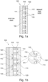
- the applicant surprisingly and unexpectedly developed a new Anti-noise shim 100 comprising at least a perforated metal layer 110 and at least a high temperature resistant layer 120 faced/coupled together by mechanical bonding wherein the perforated metal layer comprises through holes 111 and sharped/pointed mechanical bonding means 112, a continuous high temperature resistant layer 120, in particular a continuous high temperature resistant layer 120 in correspondence of the through holes 111 of the perforated metal layer 110, as clearly reported in the figures, such as fig. 1a, 1b , 3a , 3b , and the high temperature resistant layer comprises fibres, a filler and a binder, and in particular,
- Anti-noise shim 100 comprising at least a perforated metal layer 110 and at least a high temperature resistant layer 120 faced/coupled together by mechanical bonding wherein the perforated metal layer comprises through holes 111 and sharped/pointed mechanical bonding means 112, a continuous high temperature resistant layer 120, in particular a continuous high temperature resistant layer 120 in correspondence of the through holes 111 of the perforated metal layer 110, as clearly reported in the figures, such as fig. 1a, 1b , 3a , 3b , and the high temperature resistant layer comprises fibres, fillers and a binder, said anti-noise shim further comprising:
- Anti-noise shim 100 comprising at least a perforated metal layer 110 and at least a high temperature resistant layer 120 faced/coupled together by mechanical bonding wherein the perforated metal layer comprises through holes 111 and sharped/pointed mechanical bonding means 112, a continuous high temperature resistant layer 120, in particular a continuous high temperature resistant layer 120 in correspondence of the through holes 111 of the perforated metal layer 110, as clearly reported in the figures, such as fig.
- the high temperature resistant layer comprises fibres, a filler and a binder, said anti-noise shim further comprising a coating layer 130 bonded on the other side/face of the perforated metal layer; or Anti-noise shim 100 comprising at least a perforated metal layer 110 and at least a high temperature resistant layer 120 faced/coupled together by mechanical bonding wherein the perforated metal layer comprises through holes 111 and sharped/pointed mechanical bonding means 112, a continuous high temperature resistant layer 120, in particular a continuous high temperature resistant layer 120 in correspondence of the through holes 111 of the perforated metal layer 110, as clearly reported in the figures, such as fig.
- the high temperature resistant layer comprises fibres, a filler and a binder, said anti-noise shim further comprising a second high temperature resistant layer 120, a continuous high temperature resistant layer 120, in particular a continuous high temperature resistant layer 120 in correspondence of the through holes 111 of the perforated metal layer 110, as clearly reported in the figures, such as fig. 1a, 1b , 3a , 3b , mechanically bonded on the other side/face of the perforated metal layer.
- a further thin coating layer 140 might be applied on the high temperature resistant layer 120 when coupled with the perforated metal layer 110.
- a perforated metal layer 110 is meant a metal layer having through holes 111, in particular a metal layer with not less than 1 through hole per 2 square centimeter (cm 2 ) of the surface of the metal layer, preferably 1 through holes/cm 2 , or 2, 3, 4, 5 or 6 through holes/cm 2 of the surface of the metal layer.
- through holes have diameter not less than 0.5 mm and not more than 3.0 mm, preferably not less than 1.0 mm and not more than 1.5 mm.
- the perforated metal layer 110 has a thickness preferably of not less than 300 ⁇ m and not more than 500 ⁇ m, more preferably not less than 360 ⁇ m and not more than 400 um.
- Such a perforated metal layer 110 may e.g be comprised of iron, zinc-plated steel, stainless steel, aluminum or the like.
- the high temperature resistant layer 120 comprises fibres, a filler and a binder.
- the binder is an elastomeric binder, but it may also be a non-elastomeric resin type binder.
- the fibres make the material stronger and less elastic in the plane without considerably affecting the compression characteristics in the normal direction.
- the fibres and the fillers reduce the amount of elastomeric binder in the layer, thereby making the layer less expensive.
- the fibres content in the high temperature resistant layer 120 is not less than 5%, or 10%, or 14%, and not more than 23% or 30% by weight. However, for some applications the fibres content may be higher than 30%, such as up to 50% or up to 80% or even up to 95 %.
- the fibres are selected from organic fibres depending on the specific application.
- organic fibres include: cellulose fibers cotton linters fibers (fibers coming from plants,in general) aromatic polyamide fibres, polyamide fibres other than aromatic polyamide fibres, polyolefine fibres, polyester fibres, polyacrylonitrile fibres, polyvinyl alcohol fibres, polyvinylchloride fibres, polyurea fibres, polyurethane fibres, polyfluorocarbon fibres, phenol fibres, or the like.
- the fibres comprises aromatic polyamide fibers.
- the fibers are selected from inorganic fiber such as carbon fibres, glass fibre, ceramic fibre, rock wool, mineral wool, fused quartz fibre, chemical processed high silica fibre, fused alumina silicate fibre, alumina continuous fibre, stabilized zirconia fibre, boron nitride fibre, alkali titanate fibre, whiskers, boron fibre, wollastonite, basalt fibre.
- the filler may be an inorganic filler such as clay, ash, talc, barium sulfate, sodium bicarbonate, graphite, lead sulfate, tripoli, wollastonite, or an organic filler.
- the binder may be an elastomeric material of rubber type such as styrene-butadiene rubber (SBR), acrylonitrile-butadiene rubber (nitrile-butadiene rubber, NBR), isoprene rubber (IR), chloroprene rubber (CR), butadiene rubber (BR), isobutylene-isoprene rubber (IIR), ethylene propylene rubber (EPM), fluoro rubber (FPM), silicone rubber (Si), chlorosulfonated polyethylene (CSM), ethylene-vinylacetate copolymers (EVA), chlorinated polyethylene (CPE), chloro-isobutane-isoprene rubber (CIIR), epichlorohydrin rubber (ECO), nitrile isoprene rubber (NIR) or the like. Elastomers other than rubbers may also be used.
- the binder is a resin type material such as a rubber modified phenolic resin, a phenolic resin, an epoxy
- the high temperature resistant layer 120 has a thickness preferably not less than 50 ⁇ m and not more than 600 ⁇ m, more preferably not less than 150 ⁇ m and not more than 300 um.
- the coating layer 130 is a visco-elastic layer.
- the visco-elastic layer may be a latex (SBR, NBR, chloroprene, acrylic or the like), synthetic resins (acrylic, phenolic or the like, PTFE, polyurethanes, a visco elastic adhesive such as an acrylic or silicone based adhesive or the like, but it may be any visco elastic material with suitable vibration absorption and thermal resistance properties at the conditions that a shim is subjected to when mounted in a disc brake.
- the coating layer 130 has a thickness preferably not less than 30 ⁇ m and not more than 200 ⁇ m, more preferably not less than 80 ⁇ m and not more than 150 um.
- Said optional thin coating layer 140 comprises thermo-resistant polymeric material such as PTFE, silicones, polyurethanes, synthetic resins, in particular with a thickness of not less than 10 ⁇ m and not more than 100 ⁇ m, preferably not less than 20 ⁇ m and not more than 80 ⁇ m.
- thermo-resistant polymeric material such as PTFE, silicones, polyurethanes, synthetic resins
- Said thin coating layer 140 is applied on the high temperature resistant layer 120 as a top layer.
- Step application or bonding of coating layer 130 and/or thin coating layer 140 can be performed in different way: rolls, bath saturation, spraying, wetting, etc.
- the anti-noise shim 100 is an advanced anti-noise shim comprising multi-layer material with its application in the brake shims. It is made by mechanically bonding at least a high temperature resistant layer 120 comprising binders, an elastomeric material of latex rubber type such as specialized Nitrile Butadiene Rubber (NBR) Styrene Binder Rubber (SBR) latex material or the like, fibres, such as inorganic fibers, and fillers, with a perforated metal layer 110.
- NBR Nitrile Butadiene Rubber
- SBR Styrene Binder Rubber
- Said perforated metal layer 110 is characterized by through holes 111 and sharped/pointed mechanical bonding means 112, jointly/united with the perforated metal layer 110 and, where present, located at the edge 113 of the through holes 111 on at least a mechanically bonding surface 114 of the perforated metal layer 110.
- Perforated metal layer 110 having through holes 111 absorbs resonant frequencies better than a solid metal layer.
- the high temperature resistant layer 120 according to the present invention is produced from adapting gasket technology, which involves infusing the binder, such as raw NBR (or SBR or other types) Latex, with fibres and fillers. Said adapted gasket technology makes the anti-noise shims according to any of the embodiments according to the present invention more temperature resistant while the perforations of the metal layer 120 make it a perfect material for high frequency noise absorption.
- the anti-noise shim according to the present invention is an advanced anti-noise shim comprising multi-layer composite wherein the perforated metal layer/sheet 110 is mechanically bonded with at least a, or sandwiched by mechanical bonding between two, high temperature resistant layer 120 comprising binders, an elastomeric material of rubber type, such as specialised Nitrile Butadiene Rubber (NBR) material, fibres, such as organic and inorganic fibers and fillers.
- NBR Nitrile Butadiene Rubber
- the high temperature resistant layer 120 is produced from adapting gasket technology, which involves infusing the binder, an elastomeric material of rubber type, preferably the raw NBR (or SBR or other types) latex, with fibres, preferably the inorganic fibres, and fillers.
- NBR (or SBR or the like) latex is a milky white liquid emulsion of synthetic rubber.
- the gasket technology is more resistant to higher temperatures than a 100% NBR coated layer.
- the perforated metal layer concept makes distribution of the high frequency vibrations much more effective and absorbed in the compound material easier.
- the mechanical bonding step (pressing the high temperature resistant layer/sheet 120, according to the present invention, on the perforated metal layer 110 characterized by through holes 111 and sharped/pointed mechanical bonding means 112, jointly/united with the perforated metal layer 110 and, where present, located at the edge 113 of the through holes 111 on at least a mechanically bonding surface 114 of the perforated metal layer 110 ) requires no gluing agent nor solvents to form a strong bond during the process. This eliminates the need of solvents used in actual technology for shim production.
- the pressure applied is sufficient to make the sharped/pointed mechanical bonding means 112 fold in on themselves to grip the perforated metal layer/sheet and the high temperature resistant layer/sheet to each other.
- mechanical bonding means 112 or “mechanical bonding means 112” according to the present invention, it is meant means of bonding / mechanical constraint 112 or means of linking 112 or means of fastener 112 for the mechanical joining between the perforated metal layer 110 coupled with the high thermal resistant layer/s 120.
- Figs. 1a and 1b schematically show a number of embodiments of anti-noise shims 100 according to the present invention with at least a perforated metal layer 110 and at least a high temperature resistant layer 120 faced/coupled together by mechanical bonding wherein the perforated metal layer comprises through holes 111.
- fig. 1a shows an anti-noise shim 100 with at least a perforated metal layer 110 and at least a high temperature resistant layer 120 faced/coupled together by mechanical bonding wherein the perforated metal layer comprises through holes 111, said anti-noise shim further comprising a coating layer 130 bonded on the other side/face of the perforated metal layer.
- the perforated metal layer 110 characterized by through holes 111 and sharped/pointed mechanical bonding means 112, preferably with hook shape, at least one or two or three or four mechanical bonding means for each through hole, said mechanical bonding means jointly/united with the perforated metal layer 110 and, where present, located at the edge 113 of the through holes 111 on at least a mechanically bonding surface 114 of the perforated metal layer 110, mechanically bonding surface on which is mechanically bonded the high temperature resistant layer 120, while the coating layer 130 is bonded on the other side/face of the perforated metal layer.
- fig. 1b shows an anti-noise shim 100 with at least a perforated metal layer 110 and at least a high temperature resistant layer 120 faced/coupled together by mechanical bonding wherein the perforated metal layer comprises through holes 111, said anti-noise shim further comprising a second high temperature resistant layer 120 mechanically bonded on the other side/face of the perforated metal layer.
- the perforated metal layer 110 characterized by through holes 111 and sharped/pointed mechanical bonding means 112, preferably with hook shape, at least one or two or three or four mechanical bonding means for each through hole, said mechanical bonding means jointly/united with the perforated metal layer 110 and, where present, located at the edge 113 of the through holes 111 on the mechanically bonding surfaces 114 of the perforated metal layer 110, mechanically bonding surfaces on which the high temperature resistant layers 120 are mechanically bonded.
- a thin coating layer 140 is, or might be, applied as top layer on a high temperature resistant layer 120.
- said method comprises the steps:
- Every of the above mentioned methods according to the present invention can optionally further comprise a step wherein a further thin coating layer 140 is applied/bonded on the high temperature resistant layer/sheet 120, in particular when the high temperature resistant layer/sheet 120 is mechanically bonded/already mechanically bonded to the perforated metal layer 110.
- the perforated metal layer/sheet 110 has through holes 111 with sharped/pointed mechanical bonding means 112, preferably with hook shape, at least one or two or three or four mechanical bonding means for each through hole, said mechanical bonding means jointly/united with the perforated metal layer/sheet 110 and, where present, located at the edge 113 of the through holes 111 on at least a mechanically bonding surface 114 of the perforated metal layer 110.
- Said perforation step when present in any embodiments of the method of producing anti-noise shim of the type according to the present invention, always precedes the step of providing the perforated metal sheet 110.
- the pressure applied is sufficient to make the sharped/pointed mechanical bonding means 112, of the perforated metal layer/sheet 110, fold in on themselves to grip the perforated metal layer/sheet 110 and the high temperature resistant layer/sheet 120 to each other, while coating film/sheet 130 is applied/bonded by printing roll, spraying, wetting, bath saturation, etc.. Also the thin coating layer/sheet/film 140 is applied/bonded by printing roll, spraying, wetting, bath saturation, etc., when present.
- the perforated metal sheet may be pre-treating with a bonding agent before the step of bonding 230/270.
- Fig. 3a - 3b show schematic examples of a continuous perforating, bonding and optionally cutting process line 300.
- Fig. 3a shows a schematic example of a continuous perforating, bonding and optionally cutting process line 300, wherein the perforated metal sheet 110, obtained by a perforation machine 310 acting on a metal sheet provided in form of coils, not represented, and the high temperature resistant sheets 120 to be bonded together, are provided in the form of coils or rolls, not represented.
- the sheets 110 and 120 are pressed together and bonded by a pair of calender rolls 330 to form a layered anti-noise shim sheet according to the present invention.
- a thin coating layer 140 is applied on the surface of the high temperature resistant layer of the layered anti-noise shim sheet by a wet application process 340.
- FIG. 3b shows a schematic example of a continuous perforating, bonding and optionally cutting process line 300, wherein the perforated metal sheet 110, obtained by a perforation machine 310 acting on a metal sheet provided in form of coils, not represented, and the high temperature resistant sheet 120 to be bonded together, are provided.
- the sheets 110, and 120 are pressed together and bonded by a pair of calender rolls 330 to form a layered sheet.
- the coating layer 130 is applied on the no-bonded surface of the perforated metal layer 110 of the layered sheet by a wet application process 370 to form anti-noise shim sheet according to the present invention.
- individual anti-noise brake shims 350 are cut out from the anti-noise shim sheet by a stamping machine 360.
- Fig 4 shows a schematic example of a disc brake 10, as an example of those disc brakes already known in the art, said disc brake 10 known in the art comprising a disc 20 arranged to rotate about the axis C-C.
- a pair of brake pads 30 each having a backing plate 40 supporting a friction member 50 on the disc side thereof, a brake calliper 60 supporting the brake pads 30 movably toward and away from opposite friction surfaces of the disc 20, and hydraulic actuating means in the form of a brake piston 70 for urging the brake pads against the disc.
- the brake piston 70 is hydraulically actuated via the fluid path 80 connected to the hydraulic brake system of a vehicle.
- the disc brake 10 the calliper housing 60 is moveable in the actuation direction of the brake piston, whereby the brake pad on the non piston side is urged against the disc by a calliper finger 90 of the calliper housing 60.
- An anti-noise shim 100 is arranged adjacent the backing plate 40 of each disc pad 30 and the brake force from the brake piston 70 and calliper finger 65 respectively is transferred to the brake pads 30 via the anti noise shims 100.
- the expression “brake pad side” refers to the side of an anti noise shim 100 that face the backing plate 40 of a brake pad 30 and the expression “piston side” refers to the non pad side, i.e. the side that faces the piston 70 or the calliper finger 90.
- the calliper finger 90 is omitted and the calliper 60 is provided with brake pistons 70 on both sides of the disc 20.
- the above expressions include any such non disclosed disc brake arrangements.
- disc brake arrangement comprising an anti-noise shim according to anyone of the above embodiments between the calliper and the brake pad, and the disc brake may be arranged in a suitable vehicle -such as a car, truck, train, motorbike, bicycle etc.
- a method to prevent noise in a disc brake comprising the step of arranging an anti-noise shim according to anyone of the above embodiments between the calliper and the brake pad.
Landscapes
- Engineering & Computer Science (AREA)
- General Engineering & Computer Science (AREA)
- Mechanical Engineering (AREA)
- Braking Arrangements (AREA)
- Laminated Bodies (AREA)
- Exhaust Silencers (AREA)
- Gasket Seals (AREA)
- Polishing Bodies And Polishing Tools (AREA)
- Diaphragms For Electromechanical Transducers (AREA)
Claims (17)
- Geräuschdämpfende Scheibe (100), umfassend mindestens eine perforierte Metallschicht (110) und mindestens eine hochtemperaturresistente Schicht (120), die durch mechanische Bindung miteinander verbunden/gekoppelt sind, wobei die perforierte Metallschicht Durchgangslöcher (111) und mechanische Bindungsmittel (112) umfasst, und die hochtemperaturresistente Schicht Fasern, ein Füllstoff- und ein Bindematerial umfasst, wobei die perforierte Metallschicht 110 durch Durchgangslöcher (111) und scharfkantige/spitzige mechanische Bindungsmittel (112) gekennzeichnet ist, die gemeinsam/verbunden mit der perforierten Metallschicht 110 sind und, sofern anwesend, an der Kante 113 der Durchgangslöcher (111) auf mindestens einer mechanischen Bindungsoberfläche (114) der perforierten Metallschicht 110 angeordnet sind.
- Geräuschdämpfende Scheibe nach Anspruch 1, ferner umfassend eine Beschichtungsschicht (130), die auf der anderen Seite/Fläche der perforierten Metallschicht gebunden ist.
- Geräuschdämpfende Scheibe nach Anspruch 1, ferner umfassend eine zweite hochtemperaturresistente Schicht (120), die mechanisch auf der anderen Seite/Fläche der perforierten Metallschicht gebunden ist.
- Geräuschdämpfende Scheibe nach einem der vorstehenden Ansprüche, wobei eine weitere dünne Beschichtungsschicht (140) auf die hochtemperaturresistente Schicht (120) angewandt/gebunden ist.
- Geräuschdämpfende Scheibe nach einem der vorstehenden Ansprüche, wobei der Faserinhalt nach Gewicht in der hochtemperaturresistenten Schicht 95 % oder weniger, vorzugsweise 50 % oder weniger, besonders bevorzugt 30 % oder weniger und noch bevorzugter 23 % oder weniger ist.
- Geräuschdämpfende Scheibe nach einem der vorstehenden Ansprüche, wobei die thermoresistenten Fasern synthetische organische Fasern wie Zellulosefasern, Baumwollinterfasern (aus Pflanzen stammende Fasern im Allgemeinen), aromatische Polyamidfasern, Aramidfasern, andere Polyamidfasern als aromatische Polyamidfasern, Polyolefinfasern, Polyesterfasern, Polyacrylnitrilfasern, Polyvinylalkoholfasern, Polyvinylchloridfasern, Polyharnstofffasern, Polyurethanfasern, Polyfluorkohlenstofffasern, Phenolfasern und/oder anorganische Fasern wie Kohlenstofffasern, Glasfasern, Keramikfasern, Steinwolle, Mineralwolle, geschmolzene Quarzfasern, chemisch verarbeitete Fasern mit hohem Siliziumdioxidgehalt, geschmolzene Aluminiumsilikatfasern, kontinuierliche Aluminiumoxidfasern, stabilisierte Zirkoniumdioxidfasern, Bornitridfasern, Alkalitititanatfasern, Whisker, Borfasern, Wollastonit, Basaltfasern umfassen.
- Geräuschdämpfende Scheibe nach einem der vorstehenden Ansprüche, wobei das Füllstoffmaterial ein anorganisches Füllstoffmaterial wie Ton, Asche, Talk, Bariumsulfat, Natriumbikarbonat, Graphit, Bleisulfat, Tripoli, Wollastonit oder einen organischen Füllstoff umfasst.
- Geräuschdämpfende Scheibe nach einem der vorstehenden Ansprüche, wobei das Bindematerial ein elastomeres Material vom Latex-/Kautschuk-Typ wie Styrol-Butadien-Kautschuk (SBR), Acrylnitril-Butadien-Kautschuk (NitrilKautschuk, NBR), Isopren-Kautschuk (IR), Chloropren-Kautschuk (CR), Butadien-Kautschuk (BR), Isobutylen-Isopren-Kautschuk IIR), Ethylen-Propylen-Kautschuk (EPM), Fluor-Kautschuk (FPM), Silizium-Kautschuk (Si), chlorsulfoniertes Polyethylen (CSM), Ethylen-Vinylacetat-Copolymere (EVA), chloriertes Polyethylen (CPE), Chlor-Isobutan-Isopren-Kautschuk (CIIR), Epichlorhydrin-Kautschuk (ECO), Nitril-Isopren-Kautschuk (NIR) oder dergleichen umfasst, oder das Bindematerial ein harzartiges Material wie ein mit Kautschuk modifiziertes Phenolharz, ein Phenolharz, ein Epoxidharz oder dergleichen umfasst.
- Geräuschdämpfende Scheibe nach einem der vorstehenden Ansprüche, wobei die Beschichtungsschicht eine viskoelastische Schicht ist.
- Verfahren zum Herstellen einer geräuschdämpfenden Scheibe (100) nach Anspruch 1 und/oder 2 und/oder 3, das Verfahren umfassend die Schritte:- Bereitstellen eines perforierten Metallblechs (110), umfassend Durchgangslöcher (111) und mechanische Bindungsmittel (112),- mechanisches Binden durch Anwenden von Druck oder Druck und Temperatur eines hochtemperaturresistenten Blechs (120), umfassend Fasern, einen Füllstoff und ein Bindemittel, auf mindestens einer Seite des perforierten Metallblechs, um ein geräuschdämpfendes Scheibe blech zu bilden.
- Verfahren nach Anspruch 10, umfassend die Schritte:- Bereitstellen eines weiteren hochtemperaturresistenten Blechs (120),- mechanisches Binden durch Anwenden von Druck oder Druck und Temperatur des weiteren hochtemperaturresistenten Blechs auf mindestens einer nicht gebundenen Seite des perforierten Metallblechs.
- Verfahren nach Anspruch 10, umfassend die Schritte:- Bereitstellen eines Beschichtungsblechs (130),- Binden des Beschichtungsblechs auf mindestens einer nicht gebundenen Seite des perforierten Metallblechs.
- Verfahren nach einem der Ansprüche 10 bis 12, wobei das Binden ein kontinuierliches Walzen beinhaltet.
- Geräuschdämpfende BremsScheibe, umfassend eine geräuschdämpfende Scheibe nach einem der Ansprüche 1 bis 9.
- Verfahren zur Verhinderung von Geräuschen in einer Scheibenbremse, umfassend den Schritt des Anordnens der geräuschdämpfenden BremsScheibe nach Anspruch 14 zwischen dem Bremssattel und dem Bremsbelag.
- Scheibenbremsanordnung (10), umfassend die geräuschdämpfende BremsScheibe nach Anspruch 14 zwischen dem Sattel und dem Bremsbelag.
- Fahrzeug, umfassend eine Scheibenbremsanordnung nach Anspruch 16.
Applications Claiming Priority (2)
| Application Number | Priority Date | Filing Date | Title |
|---|---|---|---|
| IT102020000011902A IT202000011902A1 (it) | 2020-05-21 | 2020-05-21 | Lamina anti-rumore |
| PCT/IB2021/054200 WO2021234533A1 (en) | 2020-05-21 | 2021-05-17 | Anti-noise shim |
Publications (3)
| Publication Number | Publication Date |
|---|---|
| EP4153881A1 EP4153881A1 (de) | 2023-03-29 |
| EP4153881B1 true EP4153881B1 (de) | 2024-11-20 |
| EP4153881C0 EP4153881C0 (de) | 2024-11-20 |
Family
ID=71784591
Family Applications (1)
| Application Number | Title | Priority Date | Filing Date |
|---|---|---|---|
| EP21726467.0A Active EP4153881B1 (de) | 2020-05-21 | 2021-05-17 | Geräuschdämpfender shim |
Country Status (11)
| Country | Link |
|---|---|
| US (1) | US12435764B2 (de) |
| EP (1) | EP4153881B1 (de) |
| JP (1) | JP7785360B2 (de) |
| KR (1) | KR20230012037A (de) |
| CN (1) | CN115667753A (de) |
| BR (1) | BR112022023243A2 (de) |
| ES (1) | ES3013561T3 (de) |
| IT (1) | IT202000011902A1 (de) |
| MX (1) | MX2022014572A (de) |
| PL (1) | PL4153881T3 (de) |
| WO (1) | WO2021234533A1 (de) |
Families Citing this family (4)
| Publication number | Priority date | Publication date | Assignee | Title |
|---|---|---|---|---|
| IT202300018630A1 (it) * | 2023-09-11 | 2025-03-11 | Omnia Advanced Mat S R L | Lamina antirumore ulteriormente migliorata e relativo metodo di produzione |
| WO2025057043A1 (en) * | 2023-09-11 | 2025-03-20 | Omnia Advanced Materials S.R.L. | Improved anti-noise shim and further improved anti-noise shim and its production method |
| IT202300018627A1 (it) * | 2023-09-11 | 2025-03-11 | Omnia Advanced Mat S R L | Lamina anti rumore migliorata e relativo metodo di produzione |
| IT202300024480A1 (it) | 2023-11-17 | 2025-05-17 | Omnia Advanced Mat S R L | Lamina antirumore ancor più migliorata e relativo metodo di produzione |
Family Cites Families (9)
| Publication number | Priority date | Publication date | Assignee | Title |
|---|---|---|---|---|
| JPH11223230A (ja) * | 1998-02-04 | 1999-08-17 | Yuusan Gasket Kk | ディスクブレーキの鳴き防止用シムおよびディスクブレーキ |
| JP3546373B2 (ja) * | 2000-02-21 | 2004-07-28 | 株式会社エンドレスプロジェクト | ディスクブレーキ用摩擦パッド |
| JP2002295548A (ja) * | 2001-03-30 | 2002-10-09 | Nichias Corp | 制振シム構造体 |
| KR20040078878A (ko) * | 2003-03-06 | 2004-09-13 | 니찌아스 카부시키카이샤 | 잡음방지용 심 및 그 부착구조체 |
| JP2004301157A (ja) * | 2003-03-28 | 2004-10-28 | Nichias Corp | 鳴き防止シム構造体およびそれを備えたディスクブレーキ装置 |
| WO2008133556A1 (en) * | 2007-04-25 | 2008-11-06 | Trelleborg Rubore Ab | Anti-squeal shim |
| CA2725910A1 (en) * | 2010-12-16 | 2012-06-16 | Anstro Manufacturing, Inc. | Brake pad assembly with embedded shim |
| CA2821897C (en) * | 2013-07-26 | 2016-08-16 | Ray Arbesman | Metal and graphite laminate |
| DE102014006646A1 (de) * | 2014-05-07 | 2015-11-12 | Wolverine Advanced Materials Gmbh | Dämpfungsblech |
-
2020
- 2020-05-21 IT IT102020000011902A patent/IT202000011902A1/it unknown
-
2021
- 2021-05-17 ES ES21726467T patent/ES3013561T3/es active Active
- 2021-05-17 BR BR112022023243A patent/BR112022023243A2/pt unknown
- 2021-05-17 MX MX2022014572A patent/MX2022014572A/es unknown
- 2021-05-17 PL PL21726467.0T patent/PL4153881T3/pl unknown
- 2021-05-17 US US17/924,129 patent/US12435764B2/en active Active
- 2021-05-17 EP EP21726467.0A patent/EP4153881B1/de active Active
- 2021-05-17 WO PCT/IB2021/054200 patent/WO2021234533A1/en not_active Ceased
- 2021-05-17 JP JP2022567824A patent/JP7785360B2/ja active Active
- 2021-05-17 CN CN202180036720.1A patent/CN115667753A/zh active Pending
- 2021-05-17 KR KR1020227044183A patent/KR20230012037A/ko active Pending
Also Published As
| Publication number | Publication date |
|---|---|
| PL4153881T3 (pl) | 2025-03-10 |
| CN115667753A (zh) | 2023-01-31 |
| EP4153881A1 (de) | 2023-03-29 |
| JP7785360B2 (ja) | 2025-12-15 |
| WO2021234533A1 (en) | 2021-11-25 |
| JP2023532174A (ja) | 2023-07-27 |
| US12435764B2 (en) | 2025-10-07 |
| ES3013561T3 (en) | 2025-04-14 |
| MX2022014572A (es) | 2022-12-15 |
| EP4153881C0 (de) | 2024-11-20 |
| BR112022023243A2 (pt) | 2023-01-10 |
| IT202000011902A1 (it) | 2021-11-21 |
| KR20230012037A (ko) | 2023-01-25 |
| US20230175561A1 (en) | 2023-06-08 |
Similar Documents
| Publication | Publication Date | Title |
|---|---|---|
| EP4153881B1 (de) | Geräuschdämpfender shim | |
| EP2140165B1 (de) | Unterlage gegen quietschen | |
| US6105736A (en) | Disc brake and anti-squeal shim therefor | |
| US7749926B2 (en) | Wet type friction member | |
| US8505696B2 (en) | Brake shim and method thereof | |
| KR101947558B1 (ko) | 디스크 브레이크용 심 | |
| EP2378152B1 (de) | Wärmeisolierungskomponente für eine Bremsvorrichtung | |
| US20150159716A1 (en) | Brake insulator with thermal barrier | |
| WO2025057043A1 (en) | Improved anti-noise shim and further improved anti-noise shim and its production method | |
| JP2013100913A (ja) | 鳴き防止シムを製造する方法、及びディスク・ブレーキの鳴きを防止するための方法 | |
| CN220488155U (zh) | 一种汽车刹车卡钳 | |
| CN215567468U (zh) | 一种带双翼片的离合器片 | |
| CN202833764U (zh) | 具有减振、吸音功能的汽车刹车片 | |
| WO2025104630A1 (en) | Even more improved anti-noise shim and its production method | |
| IT202300018630A1 (it) | Lamina antirumore ulteriormente migliorata e relativo metodo di produzione | |
| IT202300018627A1 (it) | Lamina anti rumore migliorata e relativo metodo di produzione | |
| JP3904252B2 (ja) | 摩擦材の製造方法 |
Legal Events
| Date | Code | Title | Description |
|---|---|---|---|
| STAA | Information on the status of an ep patent application or granted ep patent |
Free format text: STATUS: UNKNOWN |
|
| STAA | Information on the status of an ep patent application or granted ep patent |
Free format text: STATUS: THE INTERNATIONAL PUBLICATION HAS BEEN MADE |
|
| PUAI | Public reference made under article 153(3) epc to a published international application that has entered the european phase |
Free format text: ORIGINAL CODE: 0009012 |
|
| STAA | Information on the status of an ep patent application or granted ep patent |
Free format text: STATUS: REQUEST FOR EXAMINATION WAS MADE |
|
| 17P | Request for examination filed |
Effective date: 20221219 |
|
| AK | Designated contracting states |
Kind code of ref document: A1 Designated state(s): AL AT BE BG CH CY CZ DE DK EE ES FI FR GB GR HR HU IE IS IT LI LT LU LV MC MK MT NL NO PL PT RO RS SE SI SK SM TR |
|
| DAV | Request for validation of the european patent (deleted) | ||
| DAX | Request for extension of the european patent (deleted) | ||
| RAP3 | Party data changed (applicant data changed or rights of an application transferred) |
Owner name: OMNIA ADVANCED MATERIALS S.R.L. |
|
| GRAP | Despatch of communication of intention to grant a patent |
Free format text: ORIGINAL CODE: EPIDOSNIGR1 |
|
| STAA | Information on the status of an ep patent application or granted ep patent |
Free format text: STATUS: GRANT OF PATENT IS INTENDED |
|
| INTG | Intention to grant announced |
Effective date: 20240801 |
|
| GRAS | Grant fee paid |
Free format text: ORIGINAL CODE: EPIDOSNIGR3 |
|
| GRAA | (expected) grant |
Free format text: ORIGINAL CODE: 0009210 |
|
| STAA | Information on the status of an ep patent application or granted ep patent |
Free format text: STATUS: THE PATENT HAS BEEN GRANTED |
|
| AK | Designated contracting states |
Kind code of ref document: B1 Designated state(s): AL AT BE BG CH CY CZ DE DK EE ES FI FR GB GR HR HU IE IS IT LI LT LU LV MC MK MT NL NO PL PT RO RS SE SI SK SM TR |
|
| REG | Reference to a national code |
Ref country code: GB Ref legal event code: FG4D |
|
| REG | Reference to a national code |
Ref country code: CH Ref legal event code: EP |
|
| REG | Reference to a national code |
Ref country code: DE Ref legal event code: R096 Ref document number: 602021022094 Country of ref document: DE |
|
| REG | Reference to a national code |
Ref country code: IE Ref legal event code: FG4D |
|
| U01 | Request for unitary effect filed |
Effective date: 20241219 |
|
| U07 | Unitary effect registered |
Designated state(s): AT BE BG DE DK EE FI FR IT LT LU LV MT NL PT RO SE SI Effective date: 20250108 |
|
| PG25 | Lapsed in a contracting state [announced via postgrant information from national office to epo] |
Ref country code: HR Free format text: LAPSE BECAUSE OF FAILURE TO SUBMIT A TRANSLATION OF THE DESCRIPTION OR TO PAY THE FEE WITHIN THE PRESCRIBED TIME-LIMIT Effective date: 20241120 Ref country code: IS Free format text: LAPSE BECAUSE OF FAILURE TO SUBMIT A TRANSLATION OF THE DESCRIPTION OR TO PAY THE FEE WITHIN THE PRESCRIBED TIME-LIMIT Effective date: 20250320 |
|
| REG | Reference to a national code |
Ref country code: ES Ref legal event code: FG2A Ref document number: 3013561 Country of ref document: ES Kind code of ref document: T3 Effective date: 20250414 |
|
| PG25 | Lapsed in a contracting state [announced via postgrant information from national office to epo] |
Ref country code: NO Free format text: LAPSE BECAUSE OF FAILURE TO SUBMIT A TRANSLATION OF THE DESCRIPTION OR TO PAY THE FEE WITHIN THE PRESCRIBED TIME-LIMIT Effective date: 20250220 |
|
| PG25 | Lapsed in a contracting state [announced via postgrant information from national office to epo] |
Ref country code: GR Free format text: LAPSE BECAUSE OF FAILURE TO SUBMIT A TRANSLATION OF THE DESCRIPTION OR TO PAY THE FEE WITHIN THE PRESCRIBED TIME-LIMIT Effective date: 20250221 |
|
| PG25 | Lapsed in a contracting state [announced via postgrant information from national office to epo] |
Ref country code: RS Free format text: LAPSE BECAUSE OF FAILURE TO SUBMIT A TRANSLATION OF THE DESCRIPTION OR TO PAY THE FEE WITHIN THE PRESCRIBED TIME-LIMIT Effective date: 20250220 |
|
| U20 | Renewal fee for the european patent with unitary effect paid |
Year of fee payment: 5 Effective date: 20250402 |
|
| U1N | Appointed representative for the unitary patent procedure changed after the registration of the unitary effect |
Representative=s name: GREGORJ S.R.L.; IT |
|
| PG25 | Lapsed in a contracting state [announced via postgrant information from national office to epo] |
Ref country code: SM Free format text: LAPSE BECAUSE OF FAILURE TO SUBMIT A TRANSLATION OF THE DESCRIPTION OR TO PAY THE FEE WITHIN THE PRESCRIBED TIME-LIMIT Effective date: 20241120 |
|
| PGFP | Annual fee paid to national office [announced via postgrant information from national office to epo] |
Ref country code: PL Payment date: 20250430 Year of fee payment: 5 |
|
| PGFP | Annual fee paid to national office [announced via postgrant information from national office to epo] |
Ref country code: ES Payment date: 20250616 Year of fee payment: 5 |
|
| PG25 | Lapsed in a contracting state [announced via postgrant information from national office to epo] |
Ref country code: SK Free format text: LAPSE BECAUSE OF FAILURE TO SUBMIT A TRANSLATION OF THE DESCRIPTION OR TO PAY THE FEE WITHIN THE PRESCRIBED TIME-LIMIT Effective date: 20241120 |
|
| PGFP | Annual fee paid to national office [announced via postgrant information from national office to epo] |
Ref country code: TR Payment date: 20250508 Year of fee payment: 5 |
|
| PG25 | Lapsed in a contracting state [announced via postgrant information from national office to epo] |
Ref country code: CZ Free format text: LAPSE BECAUSE OF FAILURE TO SUBMIT A TRANSLATION OF THE DESCRIPTION OR TO PAY THE FEE WITHIN THE PRESCRIBED TIME-LIMIT Effective date: 20241120 |
|
| PLBE | No opposition filed within time limit |
Free format text: ORIGINAL CODE: 0009261 |
|
| STAA | Information on the status of an ep patent application or granted ep patent |
Free format text: STATUS: NO OPPOSITION FILED WITHIN TIME LIMIT |
|
| 26N | No opposition filed |
Effective date: 20250821 |
|
| REG | Reference to a national code |
Ref country code: CH Ref legal event code: H13 Free format text: ST27 STATUS EVENT CODE: U-0-0-H10-H13 (AS PROVIDED BY THE NATIONAL OFFICE) Effective date: 20251223 |
|
| PG25 | Lapsed in a contracting state [announced via postgrant information from national office to epo] |
Ref country code: CH Free format text: LAPSE BECAUSE OF NON-PAYMENT OF DUE FEES Effective date: 20250531 |
|
| PG25 | Lapsed in a contracting state [announced via postgrant information from national office to epo] |
Ref country code: MC Free format text: LAPSE BECAUSE OF FAILURE TO SUBMIT A TRANSLATION OF THE DESCRIPTION OR TO PAY THE FEE WITHIN THE PRESCRIBED TIME-LIMIT Effective date: 20241120 |
|
| PGFP | Annual fee paid to national office [announced via postgrant information from national office to epo] |
Ref country code: GB Payment date: 20260330 Year of fee payment: 6 |
|
| PG25 | Lapsed in a contracting state [announced via postgrant information from national office to epo] |
Ref country code: IE Free format text: LAPSE BECAUSE OF NON-PAYMENT OF DUE FEES Effective date: 20250517 |