EP4153400B1 - Modulare kreisförmige platte für die additive herstellung eines teils mit einer drehachse auf einem pulverbett - Google Patents
Modulare kreisförmige platte für die additive herstellung eines teils mit einer drehachse auf einem pulverbett Download PDFInfo
- Publication number
- EP4153400B1 EP4153400B1 EP21736642.6A EP21736642A EP4153400B1 EP 4153400 B1 EP4153400 B1 EP 4153400B1 EP 21736642 A EP21736642 A EP 21736642A EP 4153400 B1 EP4153400 B1 EP 4153400B1
- Authority
- EP
- European Patent Office
- Prior art keywords
- module
- blank
- axis
- tray
- circular
- Prior art date
- Legal status (The legal status is an assumption and is not a legal conclusion. Google has not performed a legal analysis and makes no representation as to the accuracy of the status listed.)
- Active
Links
Images



Classifications
-
- B—PERFORMING OPERATIONS; TRANSPORTING
- B22—CASTING; POWDER METALLURGY
- B22F—WORKING METALLIC POWDER; MANUFACTURE OF ARTICLES FROM METALLIC POWDER; MAKING METALLIC POWDER; APPARATUS OR DEVICES SPECIALLY ADAPTED FOR METALLIC POWDER
- B22F12/00—Apparatus or devices specially adapted for additive manufacturing; Auxiliary means for additive manufacturing; Combinations of additive manufacturing apparatus or devices with other processing apparatus or devices
- B22F12/30—Platforms or substrates
- B22F12/37—Rotatable
-
- B—PERFORMING OPERATIONS; TRANSPORTING
- B29—WORKING OF PLASTICS; WORKING OF SUBSTANCES IN A PLASTIC STATE IN GENERAL
- B29C—SHAPING OR JOINING OF PLASTICS; SHAPING OF MATERIAL IN A PLASTIC STATE, NOT OTHERWISE PROVIDED FOR; AFTER-TREATMENT OF THE SHAPED PRODUCTS, e.g. REPAIRING
- B29C64/00—Additive manufacturing, i.e. manufacturing of three-dimensional [3D] objects by additive deposition, additive agglomeration or additive layering, e.g. by 3D printing, stereolithography or selective laser sintering
- B29C64/10—Processes of additive manufacturing
- B29C64/141—Processes of additive manufacturing using only solid materials
- B29C64/153—Processes of additive manufacturing using only solid materials using layers of powder being selectively joined, e.g. by selective laser sintering or melting
-
- B—PERFORMING OPERATIONS; TRANSPORTING
- B22—CASTING; POWDER METALLURGY
- B22F—WORKING METALLIC POWDER; MANUFACTURE OF ARTICLES FROM METALLIC POWDER; MAKING METALLIC POWDER; APPARATUS OR DEVICES SPECIALLY ADAPTED FOR METALLIC POWDER
- B22F10/00—Additive manufacturing of workpieces or articles from metallic powder
- B22F10/20—Direct sintering or melting
- B22F10/28—Powder bed fusion, e.g. selective laser melting [SLM] or electron beam melting [EBM]
-
- B—PERFORMING OPERATIONS; TRANSPORTING
- B22—CASTING; POWDER METALLURGY
- B22F—WORKING METALLIC POWDER; MANUFACTURE OF ARTICLES FROM METALLIC POWDER; MAKING METALLIC POWDER; APPARATUS OR DEVICES SPECIALLY ADAPTED FOR METALLIC POWDER
- B22F10/00—Additive manufacturing of workpieces or articles from metallic powder
- B22F10/60—Treatment of workpieces or articles after build-up
- B22F10/66—Treatment of workpieces or articles after build-up by mechanical means
-
- B—PERFORMING OPERATIONS; TRANSPORTING
- B22—CASTING; POWDER METALLURGY
- B22F—WORKING METALLIC POWDER; MANUFACTURE OF ARTICLES FROM METALLIC POWDER; MAKING METALLIC POWDER; APPARATUS OR DEVICES SPECIALLY ADAPTED FOR METALLIC POWDER
- B22F10/00—Additive manufacturing of workpieces or articles from metallic powder
- B22F10/60—Treatment of workpieces or articles after build-up
- B22F10/68—Cleaning or washing
-
- B—PERFORMING OPERATIONS; TRANSPORTING
- B22—CASTING; POWDER METALLURGY
- B22F—WORKING METALLIC POWDER; MANUFACTURE OF ARTICLES FROM METALLIC POWDER; MAKING METALLIC POWDER; APPARATUS OR DEVICES SPECIALLY ADAPTED FOR METALLIC POWDER
- B22F12/00—Apparatus or devices specially adapted for additive manufacturing; Auxiliary means for additive manufacturing; Combinations of additive manufacturing apparatus or devices with other processing apparatus or devices
- B22F12/30—Platforms or substrates
-
- B—PERFORMING OPERATIONS; TRANSPORTING
- B29—WORKING OF PLASTICS; WORKING OF SUBSTANCES IN A PLASTIC STATE IN GENERAL
- B29C—SHAPING OR JOINING OF PLASTICS; SHAPING OF MATERIAL IN A PLASTIC STATE, NOT OTHERWISE PROVIDED FOR; AFTER-TREATMENT OF THE SHAPED PRODUCTS, e.g. REPAIRING
- B29C64/00—Additive manufacturing, i.e. manufacturing of three-dimensional [3D] objects by additive deposition, additive agglomeration or additive layering, e.g. by 3D printing, stereolithography or selective laser sintering
- B29C64/20—Apparatus for additive manufacturing; Details thereof or accessories therefor
- B29C64/245—Platforms or substrates
-
- B—PERFORMING OPERATIONS; TRANSPORTING
- B29—WORKING OF PLASTICS; WORKING OF SUBSTANCES IN A PLASTIC STATE IN GENERAL
- B29C—SHAPING OR JOINING OF PLASTICS; SHAPING OF MATERIAL IN A PLASTIC STATE, NOT OTHERWISE PROVIDED FOR; AFTER-TREATMENT OF THE SHAPED PRODUCTS, e.g. REPAIRING
- B29C64/00—Additive manufacturing, i.e. manufacturing of three-dimensional [3D] objects by additive deposition, additive agglomeration or additive layering, e.g. by 3D printing, stereolithography or selective laser sintering
- B29C64/30—Auxiliary operations or equipment
-
- B—PERFORMING OPERATIONS; TRANSPORTING
- B29—WORKING OF PLASTICS; WORKING OF SUBSTANCES IN A PLASTIC STATE IN GENERAL
- B29C—SHAPING OR JOINING OF PLASTICS; SHAPING OF MATERIAL IN A PLASTIC STATE, NOT OTHERWISE PROVIDED FOR; AFTER-TREATMENT OF THE SHAPED PRODUCTS, e.g. REPAIRING
- B29C64/00—Additive manufacturing, i.e. manufacturing of three-dimensional [3D] objects by additive deposition, additive agglomeration or additive layering, e.g. by 3D printing, stereolithography or selective laser sintering
- B29C64/30—Auxiliary operations or equipment
- B29C64/35—Cleaning
-
- B—PERFORMING OPERATIONS; TRANSPORTING
- B29—WORKING OF PLASTICS; WORKING OF SUBSTANCES IN A PLASTIC STATE IN GENERAL
- B29C—SHAPING OR JOINING OF PLASTICS; SHAPING OF MATERIAL IN A PLASTIC STATE, NOT OTHERWISE PROVIDED FOR; AFTER-TREATMENT OF THE SHAPED PRODUCTS, e.g. REPAIRING
- B29C64/00—Additive manufacturing, i.e. manufacturing of three-dimensional [3D] objects by additive deposition, additive agglomeration or additive layering, e.g. by 3D printing, stereolithography or selective laser sintering
- B29C64/30—Auxiliary operations or equipment
- B29C64/379—Handling of additively manufactured objects, e.g. using robots
-
- B—PERFORMING OPERATIONS; TRANSPORTING
- B29—WORKING OF PLASTICS; WORKING OF SUBSTANCES IN A PLASTIC STATE IN GENERAL
- B29C—SHAPING OR JOINING OF PLASTICS; SHAPING OF MATERIAL IN A PLASTIC STATE, NOT OTHERWISE PROVIDED FOR; AFTER-TREATMENT OF THE SHAPED PRODUCTS, e.g. REPAIRING
- B29C64/00—Additive manufacturing, i.e. manufacturing of three-dimensional [3D] objects by additive deposition, additive agglomeration or additive layering, e.g. by 3D printing, stereolithography or selective laser sintering
- B29C64/40—Structures for supporting 3D objects during manufacture and intended to be sacrificed after completion thereof
-
- B—PERFORMING OPERATIONS; TRANSPORTING
- B33—ADDITIVE MANUFACTURING TECHNOLOGY
- B33Y—ADDITIVE MANUFACTURING, i.e. MANUFACTURING OF THREE-DIMENSIONAL [3D] OBJECTS BY ADDITIVE DEPOSITION, ADDITIVE AGGLOMERATION OR ADDITIVE LAYERING, e.g. BY 3D PRINTING, STEREOLITHOGRAPHY OR SELECTIVE LASER SINTERING
- B33Y10/00—Processes of additive manufacturing
-
- B—PERFORMING OPERATIONS; TRANSPORTING
- B33—ADDITIVE MANUFACTURING TECHNOLOGY
- B33Y—ADDITIVE MANUFACTURING, i.e. MANUFACTURING OF THREE-DIMENSIONAL [3D] OBJECTS BY ADDITIVE DEPOSITION, ADDITIVE AGGLOMERATION OR ADDITIVE LAYERING, e.g. BY 3D PRINTING, STEREOLITHOGRAPHY OR SELECTIVE LASER SINTERING
- B33Y30/00—Apparatus for additive manufacturing; Details thereof or accessories therefor
-
- B—PERFORMING OPERATIONS; TRANSPORTING
- B33—ADDITIVE MANUFACTURING TECHNOLOGY
- B33Y—ADDITIVE MANUFACTURING, i.e. MANUFACTURING OF THREE-DIMENSIONAL [3D] OBJECTS BY ADDITIVE DEPOSITION, ADDITIVE AGGLOMERATION OR ADDITIVE LAYERING, e.g. BY 3D PRINTING, STEREOLITHOGRAPHY OR SELECTIVE LASER SINTERING
- B33Y40/00—Auxiliary operations or equipment, e.g. for material handling
- B33Y40/20—Post-treatment, e.g. curing, coating or polishing
-
- Y—GENERAL TAGGING OF NEW TECHNOLOGICAL DEVELOPMENTS; GENERAL TAGGING OF CROSS-SECTIONAL TECHNOLOGIES SPANNING OVER SEVERAL SECTIONS OF THE IPC; TECHNICAL SUBJECTS COVERED BY FORMER USPC CROSS-REFERENCE ART COLLECTIONS [XRACs] AND DIGESTS
- Y02—TECHNOLOGIES OR APPLICATIONS FOR MITIGATION OR ADAPTATION AGAINST CLIMATE CHANGE
- Y02P—CLIMATE CHANGE MITIGATION TECHNOLOGIES IN THE PRODUCTION OR PROCESSING OF GOODS
- Y02P10/00—Technologies related to metal processing
- Y02P10/25—Process efficiency
Definitions
- the present invention relates to the field of additive manufacturing on a powder bed of a part with an axis of revolution, and more particularly to a plate used for the implementation of this manufacturing technique, also called 3D manufacturing.
- the material in powder form can be metallic, ceramic or polymer (e.g. PEEK). It is specified that in the context of this application, the term “metallic” includes pure metals and alloys.
- These techniques generally consist of selective melting or selective sintering processes on a powder bed such as described in document [1], which usually include a step during which a first layer of powder is deposited on a manufacturing plate. a metal, a metal alloy, a ceramic or a polymer of controlled thickness, then a step consisting of heating with a heating means (for example a laser or an electron beam) a predefined zone of the powder layer, and proceed by repeating these steps for each additional layer, until you obtain, slice by slice, the final piece.
- a heating means for example a laser or an electron beam
- the manufacturing process requires a succession of operations, including separation of the part from the plate by saw cutting, by electroerosion (EDM for “Electrical Discharge Machining), etc., before starting the following machining operations.
- EDM Electroerosion
- the cutting operation generates delays (positioning of the plate on the cutting machine, cutting time, cleaning after cutting, etc.).
- this operation is an additional operation further exposing the metal part to the risk of corrosion.
- the desired objective is the overall optimization of the manufacturing range (melting/sintering and machining) of parts with an axis of revolution in additive manufacturing on a powder bed (in particular by SLM (for “Selective Laser Melting” in English), by EBM (for “Electron Beam Melting” in English), by SLS (for “Selective Laser Sintering” in English)), in particular pinions, in particular for the production of parts with stages of increasing diameters of large amplitude, such as pinions with sails at mid-hub height.
- SLM Selective Laser Melting
- EBM for “Electron Beam Melting” in English
- SLS for “Selective Laser Sintering” in English
- pinions in particular for the production of parts with stages of increasing diameters of large amplitude, such as pinions with sails at mid-hub height.
- the invention aims in particular to provide a simple and effective solution to the problems raised above.
- the invention proposes a circular modular plate for the additive manufacturing on a powder bed of a part with an axis of revolution, characterized in that it consists of an assembly of modules which are coupled concentrically according to an axis and contiguous in a radial direction, the modules comprising an annular peripheral module and a circular central module, and in which, each module comprising, in an axial direction, an upper face, intended to be in contact with the powder bed, and a lower face, the lower face of each module is provided with at least one means configured to facilitate an installation of the module on a lathe of a machining device by turning, said means being chosen from a protuberance (for example of the cone type) or a recess of the notch or groove type.
- the modules of the board fit into each other concentrically.
- the modules Preferably, the modules have a circular outline.
- the assembly comprises at least one annular intermediate module located between the annular peripheral module and the circular central module.
- the assembly of modules forms a flat upper main face.
- each module is secured to the adjacent module by a solution to be agreed, for example by screwing, or even via a radial adjustment and an axial stopping means making it possible to ensure flatness of the plate thus obtained by the joining of the two modules. , compatible with the installation of powder layers.
- each module comprises a shoulder, located on a radially outer side surface, configured to form an axial abutment against a shoulder located on a radially inner side surface of an adjacent module.
- the invention also proposes a planar support comprising, in an upper face, at least one open cavity configured to receive a circular modular tray as described above, the open cavity having a shape complementary to the shape of the circular modular tray.
- the planar support has several open cavities. This makes it possible to optimize the loading of the additive manufacturing machine.
- the invention also proposes a planar assembly for the additive manufacturing on a powder bed of at least one part with an axis of revolution, comprising such a planar support and a modular plate as described above for each of the open cavities of the planar support .
- the operation of separating the raw part from the plate is now integrated into the machining operations of the part. Due to the particular shape of the modular plate, the raw part resulting from additive manufacturing can be mounted directly on the machining means, which saves an operation during which the part could be exposed to corrosion problems.
- the additive manufacturing plate is circular and is arranged geometrically in such a way that it can be mounted - after depowdering - on a lathe and thus insert the part/plate separation operation among the turning operations of roughing and finishing of the part.
- the tray according to the invention is circular and modular.
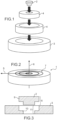
- the plate 1 comprises at least a central circular module 2 and a peripheral annular module 3. But it can also include one or more intermediate annular modules 4, located between these two modules. Indeed, in order to allow modularity of the circular plate 1 which is compatible with several references of parts with an axis of revolution (several external diameters, several internal hub diameters, etc.), the plate can comprise n annular module(s). Intermediate (s) 4 (n being an integer greater than or equal to 1), arranged between the central circular plate 2 and the peripheral annular module 3. In the figure 1 , the plate 1 comprises two intermediate annular modules 4.
- the number of modules, as well as their dimensions, must be defined on a case-by-case basis by the part manufacturer, in order to optimize them as best as possible according to the number of references, while being compatible with the dimensions of the additive manufacturing machine, as well as of the turn.
- the modules of the plate mate contiguously in a radial direction 5 of the plate and concentrically with each other (relative to a concentric axis 6) to form a circular plate 1 having a flat upper main face 7.
- the advantage of a modular circular table whose modules fit into each other concentrically is that the support elements necessary for the manufacture of the part and which are located near the center of the table are accessible to a turning tool.
- the supports necessary for manufacturing the inner hub of a sprocket are made accessible.
- the part/platter separation can be done using this tool according to a cutting plane perpendicular to the turning axis (which corresponds to the concentric axis of the platter).
- At least one module of the assembly comprises, on its radially external lateral surface 8, a shoulder 9 intended to bear against a shoulder 10 located on the radially internal lateral surface 11 of an adjacent module.
- a shoulder 9 intended to bear against a shoulder 10 located on the radially internal lateral surface 11 of an adjacent module.
- the central circular module 2 and the peripheral annular module 3 which comprise the shoulder 9 and the shoulder 10 respectively on their radially external 8 and internal 11 side surfaces.
- At least one module comprises, on its lower main face 12, at least one recess (for example a notch 13 or a groove 14) configured to facilitate the installation and maintenance of the tray/assembly. part on the machining lathe.
- at least one recess for example a notch 13 or a groove 14
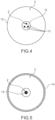
- the lower main face of a tray according to the invention obtained by assembling a central circular module 2 and a peripheral annular module 3.
- the central circular module 2 has three notches 13, which are arranged near the center of the module.
- said at least one means configured to facilitate installation of the module on a lathe of a turning machining device, chosen from a protuberance or a notch or groove type recess is also present on the peripheral annular module 3 , but is not shown.
- the central circular module has a central notch 13 and the peripheral annular module 3 includes a groove 14 located at the periphery of said module.
- a planar support 15 comprising four open cavities 16, each configured to receive a circular modular tray 1, thus forming a planar assembly 17.
- a planar assembly 17 comprising four open cavities 16, each configured to receive a circular modular tray 1, thus forming a planar assembly 17.
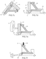
- only two modules are represented in the Figure 6 .
- the plate used here comprises two modules: a central circular module 2 and a peripheral annular module 3.
- these two modules are assembled to form a circular plate 1 ( figure 7a ) and the plate is placed in an additive manufacturing device on a powder bed.
- the powder used can be metallic, ceramic or polymer.
- the raw part 20 is produced layer by layer by a conventional additive manufacturing process.
- line A in broken lines, which also represents the axis of revolution 26 of the piece to be made.
- the part and the support elements are for example constructed layer by layer by selective melting or selective sintering of the powder 19 at the same time.
- the powder 19 having an average particle size of between 10 and 50 ⁇ m, or using an electron beam 18, the powder 19 having an average particle size of between 50 and 100 ⁇ m.
- the part to be produced comprises in particular an internal hub 22 and a peripheral rim 23, the internal hub 22 being connected to the central circular module 2 via a first support element 21 and the peripheral rim 23 being connected to the peripheral annular module 3 via another support element 21.
- These two support elements 21 are produced, like the part, by selective melting or selective sintering of the powder. Generally, they are made openwork in order to allow the passage of powder 19 during depowdering of the part. They can, for example, have the shape of crosspieces. It will be noted that each support element 21 is produced on a single module, which allows the possible detachment (by separation by cutting) of one module while the other is still attached to the part.
- Powder removal can be done by suction, blowing, vibration or even by inverting the raw part so that the powder escapes by gravity.
- the modules are put in place to form the plate 1 ( figure 8a ) and the latter is placed in a powder bed additive manufacturing device.
- the part is then produced by localized fusion or localized sintering of the powder ( figure 8b ).
- the part does not have an internal hub.
- Only the rim 23 is connected to the plate 1 by a support element 21. More precisely, it is the peripheral annular plate 3 which is connected to the part via the support element 21.
- the central circular module 2 has the function of providing a flat surface to spread the layer of powder.
- the central circular module 2 is removed (which is not connected to the part) and the part is de-powdered ( figure 8c ).
- the support elements 21 in these two embodiments can be removed by conventional machining means using a lathe.
- modules used in the production of a part are reusable for the manufacture of another part, after having applied to them a possible grinding operation to obtain a flatness of the assembly capable of receiving the layers of powder.
Landscapes
- Engineering & Computer Science (AREA)
- Chemical & Material Sciences (AREA)
- Materials Engineering (AREA)
- Manufacturing & Machinery (AREA)
- Physics & Mathematics (AREA)
- Optics & Photonics (AREA)
- Mechanical Engineering (AREA)
- Plasma & Fusion (AREA)
- Robotics (AREA)
- Powder Metallurgy (AREA)
- Medical Preparation Storing Or Oral Administration Devices (AREA)
- Pallets (AREA)
- Coating Apparatus (AREA)
Claims (8)
- Kreisförmige modulare Schale (1) für die additive Fertigung eines Werkstücks mit einer Rotationsachse (26) auf einem Pulverbett, dadurch gekennzeichnet, dass sie aus einer Anordnung von Modulen besteht, die konzentrisch entlang einer Achse (6) und aneinander angrenzend entlang einer radialen Richtung (5) gekoppelt sind, wobei die Module ein ringförmiges Peripheriemodul (3) und ein kreisförmiges Zentralmodul (2) umfassen,und wobei jedes Modul entlang einer axialen Richtung (6) eine obere Fläche, die dazu bestimmt ist, mit dem Pulverbett in Kontakt zu sein, und eine untere Fläche (12) enthält,wobei die modulare Schale dadurch gekennzeichnet ist, dass die untere Fläche jedes Moduls mit mindestens einem Mittel versehen ist, das dazu konfiguriert ist, das Platzieren des Moduls auf einer Drehbank einer Drehbearbeitungsvorrichtung zu erleichtern, wobei das Mittel aus einem Vorsprung oder einer Vertiefung vom Typ Kerbe (13) oder Nut (14) ausgewählt wird.
- Kreisförmige modulare Schale nach Anspruch 1, dadurch gekennzeichnet, dass die Anordnung mindestens ein ringförmiges Zwischenmodul (4) umfasst, das sich zwischen dem ringförmigen Umfangsmodul und dem kreisförmigen Zentralmodul befindet.
- Kreisförmige modulare Schale nach Anspruch 1 oder Anspruch 2, dadurch gekennzeichnet, dass die Anordnung von Modulen eine flache obere Hauptfläche (7) bildet.
- Kreisförmige modulare Schale nach einem der Ansprüche 1 bis 3, dadurch gekennzeichnet, dass jedes Modul eine Schulter (9) umfasst, die sich auf einer radial äußeren Seitenfläche (8) befindet und dazu konfiguriert ist, einen axialen Anschlag gegen eine Schulter (10) zu bilden, die sich auf einer radial inneren Seitenfläche (11) eines benachbarten Moduls befindet.
- Flacher Träger (15), der in einer oberen Fläche mindestens einen offenen Hohlraum (16) enthält, der dazu konfiguriert ist, eine kreisförmige modulare Schale (1) nach einem der Ansprüche 1 bis 4 aufzunehmen, wobei der offene Hohlraum eine Form aufweist, die komplementär mit der Form der kreisförmigen modularen Schale ist.
- Flache Anordnung (17) für die additive Fertigung mindestens eines Werkstücks mit einer Rotationsachse auf einem Pulverbett, umfassend einen flachen Träger (15) nach Anspruch 5 und eine modulare Schale (1) nach einem der Ansprüche 1 bis 4 für jeden der offenen Hohlräume (16) des flachen Trägers.
- Verfahren zum Fertigen eines Werkstücks mit einer Rotationsachse, umfassend:- Herstellen eines Rohlings (20) und mindestens eines Trägerelements (21) für den Rohling durch örtliches Verschmelzen oder örtliches Sintern eines Pulvers (19) auf einer modularen kreisförmigen Schale (1) nach einem der Ansprüche 1 bis 4, wobei der Rohling über das mindestens eine Trägerelement fest mit der modularen kreisförmigen Schale verbunden ist und der Rohling eine Rotationsachse (26) aufweist, die mit der konzentrischen Achse (6) der Module der Schale zusammenfällt;- Entpulvern des so erhaltenen Rohlings;- wenn die Schale ein oder mehrere Module enthält, die nicht fest mit dem Rohling verbunden sind, Entfernen dieses oder dieser Module;- Platzieren des Rohlings und des oder der Module, die fest mit dem Rohling verbunden sind, auf einer Drehbank einer Drehbearbeitungsvorrichtung, wobei das mindestens eine Mittel aus einem Vorsprung oder einer Vertiefung vom Typ Kerbe (13) oder Nut (14) ausgewählt wird und sich auf der unteren Fläche jedes Moduls befindet, um das Platzieren des Moduls auf der Drehbank der Drehbearbeitungsvorrichtung zu erleichtern;- Drehbearbeiten einer Vorderseite (B) des Rohlings;- Trennen des Rohlings von dem oder den fest verbundenen Modulen der Schale durch Drehschneiden, wobei das Schneiden an dem oder den Trägerelementen entlang einer Schnittebene (C) senkrecht zur Rotationsachse des Rohlings durchgeführt wird;- Drehbearbeiten einer Rückseite (D) des Rohlings;
wobei die Schritte des Bearbeitens (B) (D) und des Trennens durch Drehen durch Drehen des Rohlings um die konzentrische Achse (6) der Module der Schale durchgeführt werden;
wodurch das Werkstück mit einer Rotationsachse erhalten wird. - Fertigungsverfahren nach Anspruch 7, wobei während des Schritts des Herstellens des Rohlings (20) und des mindestens einen Trägerelements (21) dasselbe Trägerelement auf einem einzigen Modul verschmolzen oder gesintert wird.
Applications Claiming Priority (2)
| Application Number | Priority Date | Filing Date | Title |
|---|---|---|---|
| FR2006655A FR3111839B1 (fr) | 2020-06-25 | 2020-06-25 | Plateau modulaire circulaire pour la fabrication additive sur lit de poudre d’une pièce à axe de révolution |
| PCT/FR2021/051047 WO2021260287A1 (fr) | 2020-06-25 | 2021-06-11 | Plateau modulaire circulaire pour la fabrication additive sur lit de poudre d'une piece a axe de revolution |
Publications (2)
| Publication Number | Publication Date |
|---|---|
| EP4153400A1 EP4153400A1 (de) | 2023-03-29 |
| EP4153400B1 true EP4153400B1 (de) | 2024-08-07 |
Family
ID=72560829
Family Applications (1)
| Application Number | Title | Priority Date | Filing Date |
|---|---|---|---|
| EP21736642.6A Active EP4153400B1 (de) | 2020-06-25 | 2021-06-11 | Modulare kreisförmige platte für die additive herstellung eines teils mit einer drehachse auf einem pulverbett |
Country Status (7)
| Country | Link |
|---|---|
| US (1) | US12515257B2 (de) |
| EP (1) | EP4153400B1 (de) |
| CN (1) | CN116133775A (de) |
| CA (1) | CA3183383A1 (de) |
| FR (1) | FR3111839B1 (de) |
| PL (1) | PL4153400T3 (de) |
| WO (1) | WO2021260287A1 (de) |
Families Citing this family (3)
| Publication number | Priority date | Publication date | Assignee | Title |
|---|---|---|---|---|
| US20230294175A1 (en) * | 2022-03-15 | 2023-09-21 | Hamilton Sundstrand Corporation | Method of building additively on a billet substrate |
| SE2230446A1 (en) * | 2022-12-29 | 2024-06-30 | Seco Tools Ab | Detachable build plate |
| US20240399462A1 (en) * | 2023-05-31 | 2024-12-05 | Spirit Aerosystems, Inc. | Modular build plate and method for additive manufacturing |
Family Cites Families (12)
| Publication number | Priority date | Publication date | Assignee | Title |
|---|---|---|---|---|
| FR3030323B1 (fr) | 2014-12-23 | 2019-08-09 | Safran Aircraft Engines | Plateau de fabrication pour la fabrication de pieces par fusion selective ou frittage selectif sur lit de poudre, outillage et procede de fabrication mettant en oeuvre un tel plateau |
| JP2016203510A (ja) * | 2015-04-23 | 2016-12-08 | ダイハツ工業株式会社 | 3次元構造体を含む製品の製造方法 |
| CN108025497A (zh) * | 2015-09-16 | 2018-05-11 | 应用材料公司 | 在增材制造中底板的制造、壳体的制造和支撑支柱的制造 |
| FR3043577B1 (fr) * | 2015-11-17 | 2022-06-17 | Snecma | Procede de fabrication d'une preforme d'aube, d'une aube et d'un secteur de distributeur par fusion selective sur lit de poudre |
| DE102016209933A1 (de) | 2016-06-06 | 2017-12-07 | Eos Gmbh Electro Optical Systems | Vorrichtung und Verfahren zum generativen Herstellen eines dreidimensionalen Objekts |
| CN107617859A (zh) * | 2016-12-23 | 2018-01-23 | 合肥盛强数控设备有限公司 | 一种基于sls3d打印模具的数控机床后处理工艺 |
| FR3064519B1 (fr) * | 2017-03-29 | 2021-02-12 | Safran Aircraft Engines | Procede de fabrication d'une piece metallique par fabrication additive |
| EP3417961B1 (de) * | 2017-06-19 | 2022-07-27 | General Electric Company | Halterung zur generativen fertigung |
| DE102017118065A1 (de) | 2017-08-09 | 2019-02-14 | Karlsruher Institut für Technologie | Generative Fertigungsanlage und Verfahren zur Herstellung von Bauteilen mittels dieser generativen Fertigungsanlage |
| US20190143589A1 (en) * | 2017-11-16 | 2019-05-16 | Metal Industries Research & Development Centre | Powder bed device of additive manufacturing and additive manufacturing apparatus |
| DE102018116314A1 (de) * | 2018-07-05 | 2020-01-09 | Aesculap Ag | Bauplattform und Verfahren zur generativen Herstellung eines Bauteils, insbesondere eines Medizinprodukts wie ein Implantat |
| CN208840513U (zh) * | 2018-09-21 | 2019-05-10 | 天津镭明激光科技有限公司 | 一种增材制造激光成型系统集成设备 |
-
2020
- 2020-06-25 FR FR2006655A patent/FR3111839B1/fr active Active
-
2021
- 2021-06-11 WO PCT/FR2021/051047 patent/WO2021260287A1/fr not_active Ceased
- 2021-06-11 US US18/002,896 patent/US12515257B2/en active Active
- 2021-06-11 EP EP21736642.6A patent/EP4153400B1/de active Active
- 2021-06-11 CA CA3183383A patent/CA3183383A1/fr active Pending
- 2021-06-11 CN CN202180059757.6A patent/CN116133775A/zh active Pending
- 2021-06-11 PL PL21736642.6T patent/PL4153400T3/pl unknown
Also Published As
| Publication number | Publication date |
|---|---|
| PL4153400T3 (pl) | 2024-10-14 |
| US20230264267A1 (en) | 2023-08-24 |
| FR3111839B1 (fr) | 2022-09-02 |
| CN116133775A (zh) | 2023-05-16 |
| WO2021260287A1 (fr) | 2021-12-30 |
| FR3111839A1 (fr) | 2021-12-31 |
| EP4153400A1 (de) | 2023-03-29 |
| US12515257B2 (en) | 2026-01-06 |
| CA3183383A1 (fr) | 2021-12-30 |
Similar Documents
| Publication | Publication Date | Title |
|---|---|---|
| WO2021260287A1 (fr) | Plateau modulaire circulaire pour la fabrication additive sur lit de poudre d'une piece a axe de revolution | |
| EP3370901B1 (de) | Verfahren zur generativen fertigung eines teils, insbesondere eines verkleidungselement für eine reifenform, unter verwendung von pulver | |
| EP3377254B1 (de) | Verfahren zur herstellung einer schaufelvorform, einer schaufel und eines düsensegments durch selektive pulverbettfusion | |
| EP2709792B1 (de) | Verfahren zur herstellung eines formelement durch sinterung mit planaren unfritted teil, und entsprechendes formelement | |
| EP3218141B1 (de) | Verfahren zum reibschweissen eines blatts an eine turbomaschinenschaufel, einschliesslich eines flächenbearbeitungsverfahrens | |
| FR2939712A1 (fr) | Garniture de moule comprenant un element sacrificiel de liaison | |
| WO2011054772A1 (fr) | Plateau de support pour dispositif de frittage laser et procede de frittage ameliore | |
| EP0396899A2 (de) | Zylinderwerkzeug zum Bearbeiten von Band- oder Plattenmaterial in einer Rotationsmaschine und Herstellungsverfahren | |
| EP3468733B1 (de) | Bauplattform zur generativ herstellung mit einem plattenförmigen versteifungselement ausgestattet, das teilweise in der dicke hohlräume aufweist | |
| FR3064519A1 (fr) | Procede de fabrication d'une piece metallique par fabrication additive | |
| EP3595842B1 (de) | Verfahren zur herstellung von metalllegierungsteilen mit komplexer form | |
| FR2806763A1 (fr) | Palier composite a double roulement a billes, procede pour son montage, et outil pour la realisation d'une paire de bagues dudit palier | |
| EP1756830B2 (de) | Hülle für schräg gelagerte digitalplatten | |
| EP4110588A1 (de) | Modulare schale zur generativen fertigung eines teils mit einer rotationsachse auf einem pulverbett | |
| EP3741500B1 (de) | Verfahren zum herstellen einer mikrofräse, die integrierte kühlkanäle umfasst | |
| EP0517572B2 (de) | Verfahren zur Herstellung einer Riemenscheibe, Vorrichtung zu ihrer Herstellung und so hergestellte Riemenscheibe | |
| WO2000037816A1 (fr) | Bague de synchronisation pour un synchroniseur de boite de vitesses, et procede de fabrication du corps en tole d'une telle bague | |
| EP3499316B1 (de) | Schliesszylinderfeder für ein uhrwerk einer uhr, und herstellungsverfahren einer solchen feder | |
| EP4196300A1 (de) | Generative fertigung auf einem rohling eines turbomaschinenteils mit rauem bereich | |
| EP1675168A2 (de) | Verfahren und Vorrichtung zur Positionierung von Anschlusskugeln für integrierte Schaltungen | |
| EP4308326A1 (de) | Verfahren zur herstellung einer lüfterscheibe mit einem teil durch generative fertigung | |
| FR2968584A1 (fr) | Fraise-mere avec porte-plaquettes montes sur un moyeu | |
| CH715379B1 (fr) | Fraise-mère pour la fabrication de roues dentées horlogères. |
Legal Events
| Date | Code | Title | Description |
|---|---|---|---|
| STAA | Information on the status of an ep patent application or granted ep patent |
Free format text: STATUS: UNKNOWN |
|
| STAA | Information on the status of an ep patent application or granted ep patent |
Free format text: STATUS: THE INTERNATIONAL PUBLICATION HAS BEEN MADE |
|
| PUAI | Public reference made under article 153(3) epc to a published international application that has entered the european phase |
Free format text: ORIGINAL CODE: 0009012 |
|
| STAA | Information on the status of an ep patent application or granted ep patent |
Free format text: STATUS: REQUEST FOR EXAMINATION WAS MADE |
|
| 17P | Request for examination filed |
Effective date: 20221219 |
|
| AK | Designated contracting states |
Kind code of ref document: A1 Designated state(s): AL AT BE BG CH CY CZ DE DK EE ES FI FR GB GR HR HU IE IS IT LI LT LU LV MC MK MT NL NO PL PT RO RS SE SI SK SM TR |
|
| DAV | Request for validation of the european patent (deleted) | ||
| DAX | Request for extension of the european patent (deleted) | ||
| REG | Reference to a national code |
Ref legal event code: R079 Free format text: PREVIOUS MAIN CLASS: B29C0064153000 Ipc: B22F0010680000 Ref country code: DE Ref legal event code: R079 Ref document number: 602021016883 Country of ref document: DE Free format text: PREVIOUS MAIN CLASS: B29C0064153000 Ipc: B22F0010680000 |
|
| GRAP | Despatch of communication of intention to grant a patent |
Free format text: ORIGINAL CODE: EPIDOSNIGR1 |
|
| RIC1 | Information provided on ipc code assigned before grant |
Ipc: B22F 12/30 20210101ALI20240409BHEP Ipc: B22F 10/68 20210101AFI20240409BHEP |
|
| STAA | Information on the status of an ep patent application or granted ep patent |
Free format text: STATUS: GRANT OF PATENT IS INTENDED |
|
| INTG | Intention to grant announced |
Effective date: 20240516 |
|
| GRAS | Grant fee paid |
Free format text: ORIGINAL CODE: EPIDOSNIGR3 |
|
| GRAA | (expected) grant |
Free format text: ORIGINAL CODE: 0009210 |
|
| STAA | Information on the status of an ep patent application or granted ep patent |
Free format text: STATUS: THE PATENT HAS BEEN GRANTED |
|
| AK | Designated contracting states |
Kind code of ref document: B1 Designated state(s): AL AT BE BG CH CY CZ DE DK EE ES FI FR GB GR HR HU IE IS IT LI LT LU LV MC MK MT NL NO PL PT RO RS SE SI SK SM TR |
|
| REG | Reference to a national code |
Ref country code: GB Ref legal event code: FG4D Free format text: NOT ENGLISH |
|
| REG | Reference to a national code |
Ref country code: CH Ref legal event code: EP |
|
| REG | Reference to a national code |
Ref country code: IE Ref legal event code: FG4D Free format text: LANGUAGE OF EP DOCUMENT: FRENCH |
|
| REG | Reference to a national code |
Ref country code: DE Ref legal event code: R096 Ref document number: 602021016883 Country of ref document: DE |
|
| REG | Reference to a national code |
Ref country code: LT Ref legal event code: MG9D |
|
| REG | Reference to a national code |
Ref country code: NL Ref legal event code: MP Effective date: 20240807 |
|
| PG25 | Lapsed in a contracting state [announced via postgrant information from national office to epo] |
Ref country code: NO Free format text: LAPSE BECAUSE OF FAILURE TO SUBMIT A TRANSLATION OF THE DESCRIPTION OR TO PAY THE FEE WITHIN THE PRESCRIBED TIME-LIMIT Effective date: 20241107 |
|
| REG | Reference to a national code |
Ref country code: AT Ref legal event code: MK05 Ref document number: 1710401 Country of ref document: AT Kind code of ref document: T Effective date: 20240807 |
|
| PG25 | Lapsed in a contracting state [announced via postgrant information from national office to epo] |
Ref country code: GR Free format text: LAPSE BECAUSE OF FAILURE TO SUBMIT A TRANSLATION OF THE DESCRIPTION OR TO PAY THE FEE WITHIN THE PRESCRIBED TIME-LIMIT Effective date: 20241108 Ref country code: NL Free format text: LAPSE BECAUSE OF FAILURE TO SUBMIT A TRANSLATION OF THE DESCRIPTION OR TO PAY THE FEE WITHIN THE PRESCRIBED TIME-LIMIT Effective date: 20240807 Ref country code: FI Free format text: LAPSE BECAUSE OF FAILURE TO SUBMIT A TRANSLATION OF THE DESCRIPTION OR TO PAY THE FEE WITHIN THE PRESCRIBED TIME-LIMIT Effective date: 20240807 Ref country code: PT Free format text: LAPSE BECAUSE OF FAILURE TO SUBMIT A TRANSLATION OF THE DESCRIPTION OR TO PAY THE FEE WITHIN THE PRESCRIBED TIME-LIMIT Effective date: 20241209 |
|
| PG25 | Lapsed in a contracting state [announced via postgrant information from national office to epo] |
Ref country code: BG Free format text: LAPSE BECAUSE OF FAILURE TO SUBMIT A TRANSLATION OF THE DESCRIPTION OR TO PAY THE FEE WITHIN THE PRESCRIBED TIME-LIMIT Effective date: 20240807 |
|
| PG25 | Lapsed in a contracting state [announced via postgrant information from national office to epo] |
Ref country code: LV Free format text: LAPSE BECAUSE OF FAILURE TO SUBMIT A TRANSLATION OF THE DESCRIPTION OR TO PAY THE FEE WITHIN THE PRESCRIBED TIME-LIMIT Effective date: 20240807 |
|
| PG25 | Lapsed in a contracting state [announced via postgrant information from national office to epo] |
Ref country code: IS Free format text: LAPSE BECAUSE OF FAILURE TO SUBMIT A TRANSLATION OF THE DESCRIPTION OR TO PAY THE FEE WITHIN THE PRESCRIBED TIME-LIMIT Effective date: 20241207 Ref country code: AT Free format text: LAPSE BECAUSE OF FAILURE TO SUBMIT A TRANSLATION OF THE DESCRIPTION OR TO PAY THE FEE WITHIN THE PRESCRIBED TIME-LIMIT Effective date: 20240807 |
|
| PG25 | Lapsed in a contracting state [announced via postgrant information from national office to epo] |
Ref country code: HR Free format text: LAPSE BECAUSE OF FAILURE TO SUBMIT A TRANSLATION OF THE DESCRIPTION OR TO PAY THE FEE WITHIN THE PRESCRIBED TIME-LIMIT Effective date: 20240807 |
|
| PG25 | Lapsed in a contracting state [announced via postgrant information from national office to epo] |
Ref country code: RS Free format text: LAPSE BECAUSE OF FAILURE TO SUBMIT A TRANSLATION OF THE DESCRIPTION OR TO PAY THE FEE WITHIN THE PRESCRIBED TIME-LIMIT Effective date: 20241107 Ref country code: ES Free format text: LAPSE BECAUSE OF FAILURE TO SUBMIT A TRANSLATION OF THE DESCRIPTION OR TO PAY THE FEE WITHIN THE PRESCRIBED TIME-LIMIT Effective date: 20240807 |
|
| PG25 | Lapsed in a contracting state [announced via postgrant information from national office to epo] |
Ref country code: RS Free format text: LAPSE BECAUSE OF FAILURE TO SUBMIT A TRANSLATION OF THE DESCRIPTION OR TO PAY THE FEE WITHIN THE PRESCRIBED TIME-LIMIT Effective date: 20241107 Ref country code: PT Free format text: LAPSE BECAUSE OF FAILURE TO SUBMIT A TRANSLATION OF THE DESCRIPTION OR TO PAY THE FEE WITHIN THE PRESCRIBED TIME-LIMIT Effective date: 20241209 Ref country code: NO Free format text: LAPSE BECAUSE OF FAILURE TO SUBMIT A TRANSLATION OF THE DESCRIPTION OR TO PAY THE FEE WITHIN THE PRESCRIBED TIME-LIMIT Effective date: 20241107 Ref country code: NL Free format text: LAPSE BECAUSE OF FAILURE TO SUBMIT A TRANSLATION OF THE DESCRIPTION OR TO PAY THE FEE WITHIN THE PRESCRIBED TIME-LIMIT Effective date: 20240807 Ref country code: LV Free format text: LAPSE BECAUSE OF FAILURE TO SUBMIT A TRANSLATION OF THE DESCRIPTION OR TO PAY THE FEE WITHIN THE PRESCRIBED TIME-LIMIT Effective date: 20240807 Ref country code: IS Free format text: LAPSE BECAUSE OF FAILURE TO SUBMIT A TRANSLATION OF THE DESCRIPTION OR TO PAY THE FEE WITHIN THE PRESCRIBED TIME-LIMIT Effective date: 20241207 Ref country code: HR Free format text: LAPSE BECAUSE OF FAILURE TO SUBMIT A TRANSLATION OF THE DESCRIPTION OR TO PAY THE FEE WITHIN THE PRESCRIBED TIME-LIMIT Effective date: 20240807 Ref country code: GR Free format text: LAPSE BECAUSE OF FAILURE TO SUBMIT A TRANSLATION OF THE DESCRIPTION OR TO PAY THE FEE WITHIN THE PRESCRIBED TIME-LIMIT Effective date: 20241108 Ref country code: FI Free format text: LAPSE BECAUSE OF FAILURE TO SUBMIT A TRANSLATION OF THE DESCRIPTION OR TO PAY THE FEE WITHIN THE PRESCRIBED TIME-LIMIT Effective date: 20240807 Ref country code: ES Free format text: LAPSE BECAUSE OF FAILURE TO SUBMIT A TRANSLATION OF THE DESCRIPTION OR TO PAY THE FEE WITHIN THE PRESCRIBED TIME-LIMIT Effective date: 20240807 Ref country code: BG Free format text: LAPSE BECAUSE OF FAILURE TO SUBMIT A TRANSLATION OF THE DESCRIPTION OR TO PAY THE FEE WITHIN THE PRESCRIBED TIME-LIMIT Effective date: 20240807 Ref country code: AT Free format text: LAPSE BECAUSE OF FAILURE TO SUBMIT A TRANSLATION OF THE DESCRIPTION OR TO PAY THE FEE WITHIN THE PRESCRIBED TIME-LIMIT Effective date: 20240807 |
|
| PG25 | Lapsed in a contracting state [announced via postgrant information from national office to epo] |
Ref country code: DK Free format text: LAPSE BECAUSE OF FAILURE TO SUBMIT A TRANSLATION OF THE DESCRIPTION OR TO PAY THE FEE WITHIN THE PRESCRIBED TIME-LIMIT Effective date: 20240807 Ref country code: SM Free format text: LAPSE BECAUSE OF FAILURE TO SUBMIT A TRANSLATION OF THE DESCRIPTION OR TO PAY THE FEE WITHIN THE PRESCRIBED TIME-LIMIT Effective date: 20240807 |
|
| PG25 | Lapsed in a contracting state [announced via postgrant information from national office to epo] |
Ref country code: EE Free format text: LAPSE BECAUSE OF FAILURE TO SUBMIT A TRANSLATION OF THE DESCRIPTION OR TO PAY THE FEE WITHIN THE PRESCRIBED TIME-LIMIT Effective date: 20240807 |
|
| PG25 | Lapsed in a contracting state [announced via postgrant information from national office to epo] |
Ref country code: SK Free format text: LAPSE BECAUSE OF FAILURE TO SUBMIT A TRANSLATION OF THE DESCRIPTION OR TO PAY THE FEE WITHIN THE PRESCRIBED TIME-LIMIT Effective date: 20240807 |
|
| REG | Reference to a national code |
Ref country code: DE Ref legal event code: R097 Ref document number: 602021016883 Country of ref document: DE |
|
| PLBE | No opposition filed within time limit |
Free format text: ORIGINAL CODE: 0009261 |
|
| STAA | Information on the status of an ep patent application or granted ep patent |
Free format text: STATUS: NO OPPOSITION FILED WITHIN TIME LIMIT |
|
| PGFP | Annual fee paid to national office [announced via postgrant information from national office to epo] |
Ref country code: PL Payment date: 20250604 Year of fee payment: 5 Ref country code: DE Payment date: 20250618 Year of fee payment: 5 |
|
| PGFP | Annual fee paid to national office [announced via postgrant information from national office to epo] |
Ref country code: GB Payment date: 20250625 Year of fee payment: 5 |
|
| 26N | No opposition filed |
Effective date: 20250508 |
|
| PGFP | Annual fee paid to national office [announced via postgrant information from national office to epo] |
Ref country code: FR Payment date: 20250623 Year of fee payment: 5 |
|
| PGFP | Annual fee paid to national office [announced via postgrant information from national office to epo] |
Ref country code: CZ Payment date: 20250530 Year of fee payment: 5 |
|
| PG25 | Lapsed in a contracting state [announced via postgrant information from national office to epo] |
Ref country code: SE Free format text: LAPSE BECAUSE OF FAILURE TO SUBMIT A TRANSLATION OF THE DESCRIPTION OR TO PAY THE FEE WITHIN THE PRESCRIBED TIME-LIMIT Effective date: 20240807 |
|
| REG | Reference to a national code |
Ref country code: CH Ref legal event code: H13 Free format text: ST27 STATUS EVENT CODE: U-0-0-H10-H13 (AS PROVIDED BY THE NATIONAL OFFICE) Effective date: 20260127 |
|
| PG25 | Lapsed in a contracting state [announced via postgrant information from national office to epo] |
Ref country code: MC Free format text: LAPSE BECAUSE OF FAILURE TO SUBMIT A TRANSLATION OF THE DESCRIPTION OR TO PAY THE FEE WITHIN THE PRESCRIBED TIME-LIMIT Effective date: 20240807 |
|
| PG25 | Lapsed in a contracting state [announced via postgrant information from national office to epo] |
Ref country code: LU Free format text: LAPSE BECAUSE OF NON-PAYMENT OF DUE FEES Effective date: 20250611 |
|
| REG | Reference to a national code |
Ref country code: BE Ref legal event code: MM Effective date: 20250630 |
|
| PG25 | Lapsed in a contracting state [announced via postgrant information from national office to epo] |
Ref country code: IE Free format text: LAPSE BECAUSE OF NON-PAYMENT OF DUE FEES Effective date: 20250611 |
|
| PG25 | Lapsed in a contracting state [announced via postgrant information from national office to epo] |
Ref country code: RO Free format text: LAPSE BECAUSE OF FAILURE TO SUBMIT A TRANSLATION OF THE DESCRIPTION OR TO PAY THE FEE WITHIN THE PRESCRIBED TIME-LIMIT Effective date: 20240807 Ref country code: IT Free format text: LAPSE BECAUSE OF NON-PAYMENT OF DUE FEES Effective date: 20250611 Ref country code: BE Free format text: LAPSE BECAUSE OF NON-PAYMENT OF DUE FEES Effective date: 20250630 |
|
| PG25 | Lapsed in a contracting state [announced via postgrant information from national office to epo] |
Ref country code: CH Free format text: LAPSE BECAUSE OF NON-PAYMENT OF DUE FEES Effective date: 20250630 |