EP4153379B1 - Vorrichtung und verfahren zur markierung von oberflächen durch abrieb - Google Patents
Vorrichtung und verfahren zur markierung von oberflächen durch abrieb Download PDFInfo
- Publication number
- EP4153379B1 EP4153379B1 EP21733855.7A EP21733855A EP4153379B1 EP 4153379 B1 EP4153379 B1 EP 4153379B1 EP 21733855 A EP21733855 A EP 21733855A EP 4153379 B1 EP4153379 B1 EP 4153379B1
- Authority
- EP
- European Patent Office
- Prior art keywords
- marking
- abrasive
- group
- head
- suckers
- Prior art date
- Legal status (The legal status is an assumption and is not a legal conclusion. Google has not performed a legal analysis and makes no representation as to the accuracy of the status listed.)
- Active
Links
Images




Classifications
-
- B—PERFORMING OPERATIONS; TRANSPORTING
- B44—DECORATIVE ARTS
- B44B—MACHINES, APPARATUS OR TOOLS FOR ARTISTIC WORK, e.g. FOR SCULPTURING, GUILLOCHING, CARVING, BRANDING, INLAYING
- B44B3/00—Artists' machines or apparatus equipped with tools or work holders moving or able to be controlled substantially two-dimensionally for carving, engraving, or guilloching shallow ornamenting or markings
- B44B3/009—Artists' machines or apparatus equipped with tools or work holders moving or able to be controlled substantially two-dimensionally for carving, engraving, or guilloching shallow ornamenting or markings using a computer control means
-
- B—PERFORMING OPERATIONS; TRANSPORTING
- B24—GRINDING; POLISHING
- B24C—ABRASIVE OR RELATED BLASTING WITH PARTICULATE MATERIAL
- B24C1/00—Methods for use of abrasive blasting for producing particular effects; Use of auxiliary equipment in connection with such methods
- B24C1/04—Methods for use of abrasive blasting for producing particular effects; Use of auxiliary equipment in connection with such methods for treating only selected parts of a surface, e.g. for carving stone or glass
-
- B—PERFORMING OPERATIONS; TRANSPORTING
- B44—DECORATIVE ARTS
- B44C—PRODUCING DECORATIVE EFFECTS; MOSAICS; TARSIA WORK; PAPERHANGING
- B44C1/00—Processes, not specifically provided for elsewhere, for producing decorative surface effects
- B44C1/22—Removing surface-material, e.g. by engraving, by etching
- B44C1/221—Removing surface-material, e.g. by engraving, by etching using streams of abrasive particles
-
- B—PERFORMING OPERATIONS; TRANSPORTING
- B24—GRINDING; POLISHING
- B24C—ABRASIVE OR RELATED BLASTING WITH PARTICULATE MATERIAL
- B24C3/00—Abrasive blasting machines or devices; Plants
- B24C3/02—Abrasive blasting machines or devices; Plants characterised by the arrangement of the component assemblies with respect to each other
- B24C3/06—Abrasive blasting machines or devices; Plants characterised by the arrangement of the component assemblies with respect to each other movable; portable
-
- B—PERFORMING OPERATIONS; TRANSPORTING
- B24—GRINDING; POLISHING
- B24C—ABRASIVE OR RELATED BLASTING WITH PARTICULATE MATERIAL
- B24C5/00—Devices or accessories for generating abrasive blasts
- B24C5/02—Blast guns, e.g. for generating high velocity abrasive fluid jets for cutting materials
-
- B—PERFORMING OPERATIONS; TRANSPORTING
- B24—GRINDING; POLISHING
- B24C—ABRASIVE OR RELATED BLASTING WITH PARTICULATE MATERIAL
- B24C7/00—Equipment for feeding abrasive material; Controlling the flowability, constitution, or other physical characteristics of abrasive blasts
- B24C7/0046—Equipment for feeding abrasive material; Controlling the flowability, constitution, or other physical characteristics of abrasive blasts the abrasive material being fed in a gaseous carrier
Definitions
- the invention has been developed with particular regard for an apparatus and process for marking surfaces of vehicles by abrasion.
- the surfaces which can be marked by means of the invention may be, for example, but in a non-limiting manner, the plate glass panes of the vehicles, the headlights, the rear-view mirrors and other portions and surfaces made of glass, plate glass, plexiglass, fibreglass, plastics material, metal and the like.
- the known marking system is carried out by means of surface abrasion of the plate glass panes and commonly makes use of a marking mask which reproduces in a negative state the marking code to be reproduced on the plate glass pane.
- the marking mask is supported on the plate glass pane to be marked and there is projected against it the abrasive material which makes the glass opaque in the zones left uncovered by the marking mask, leaving printed at that location the code or the symbol desired.
- This known methodology is described, for example, in the patent documents IT 19860003412 and IT 19860003374 which date from 1986 in the name of the same inventor Roberto Muriana.
- US5461407A describes an apparatus for marking surfaces by abrasion according to the preamble of claim 1.
- US5461407A further describes a process for marking surfaces by means of an apparatus, comprising the steps of: authorizing the marking by transmitting a marking request to a remote node and receiving an authorization containing marking data which are capable of being processed by the control group in order to transmit instructions for marking to the apparatus; carrying out the marking of a surface by connecting the marking head of the apparatus to the surface and controlling the opening and closing of the shut-off valve for the flow of air and abrasive; deactivating the emission of air and abrasive at the end of the marking defined by the marking data; and disconnecting the marking head from the surface.
- the conventional marking system has a number of disadvantages which have caused the inventor to develop the innovative solution described below.
- the marking mask against which the abrasive is projected is constituted by a frame, on which there are positioned the perforated tiles of the letters and numbers to be marked. If the equipment is not used correctly and checked periodically, there are brought about various disadvantages and a gradual worsening of the quality of the marking.
- the perforated tiles of the marking mask tend to be consumed at the perimeter of the shape of the character, generating over time a marking which is not very sharp and has blurred edges.
- the perforated tiles also tend to become consumed at the external edges thereof with the result that a gap is formed between adjacent tiles and produces a marking which shows slight vertical stripes between one character and another.
- Another disadvantage is constituted by the fact that the pressure of the air compressor which provides for projecting the abrasive is not easy to control for each marking and is at risk of being too low or too high.
- the marking may appear to be light at the centre and virtually invisible at the extremities of the writing.
- excessively high pressure in addition to the fact that the marking is coarse, especially at the centre of the marking mask, both the perforated tiles of the marking mask and the nozzle for dispensing the abrasive become degraded more rapidly.
- Another disadvantage of the conventional system is the difficulty in correctly positioning the equipment on the plate glass panes or on the optical units of vehicles, especially if they have a given curvature, with the risk that the poor positioning may leave a space between the marking head of the equipment and the surface to be marked, affecting the good completion of the marking.
- Another problem of the conventional marking is the fact that it is impossible to check that the operator places the correct code on the vehicle and therefore that it is impossible to prevent errors if not even occurrences of fraud in the marking process, which is critical per se during the subsequent administration of the marked vehicle for anti-theft or insurance purposes.
- the head of the apparatus is anchored to the glass or more generally to the surface to be marked via very powerful suckers which allow the operator not to have to hold the equipment via the handle thereof during the marking operation.
- the fixing of the head by the adhesion provided by the suckers allows repetition of the marking operation on the same surface until the pressure of the suckers is reduced in order to remove the head.
- the secure anchoring provided by the suckers allows the position of the head to be kept steady for the whole of the time necessary.
- the apparatus of the invention is capable of autonomously managing the flow of air/abrasive admixture in order to dispense the correct dose of abrasive and at the correct operating pressure.
- the equipment is configured in such a manner that the predefined marking area can be positioned at the edge of a surface, for example, at the edge of a plate glass pane of the vehicle, behind a frame portion which projects further than the surface to be marked.
- the predefined marking area can be positioned at the edge of a surface, for example, at the edge of a plate glass pane of the vehicle, behind a frame portion which projects further than the surface to be marked.
- the marking of the QR code on the black strip of the windscreen has the substantial advantage of generating a good light/dark contrast for the optical detection of the code with commercial readers.
- an apparatus for marking surfaces by abrasion which comprises a dispensing group for a flow of air and abrasive.
- the flow is conveyed to a marking nozzle which is advantageously mounted in a movable manner on a marking head.
- a selective shut-off valve for the flow of air and abrasive.
- a control group is configured to control both the selective opening and closing of the shut-off valve and the movement of the marking nozzle with respect to the marking head in a marking plane.
- the marking plane is substantially transverse to an emission direction of the mixture of air and abrasive from the marking nozzle on a surface to be marked.
- the marking nozzle can be mounted on a system of at least two carriages which are movable in translation in the marking plane in two mutually orthogonal directions by means of respective motorized transmissions which are controlled by the control group.
- the marking nozzle and the shut-off valve are mounted on a movable marking group in the marking plane.
- the marking group comprises a head which is intended to be supported against the surface to be marked.
- the head may comprise resilient members in order to be adapted to the formation of the surface to be marked.
- a suction group can be connected to the marking group in order to draw in the abrasive emitted by the marking nozzle during the marking of the surface.
- the resilient members may comprise self-aligning bearings which are relatively compressible and which are arranged at the end of the head for the support against the surface to be marked. Additionally or alternatively, the resilient members may comprise resilient means which apply a resilient thrust to a retractable support member on which the marking nozzle is mounted.
- a process for marking surfaces by means of an apparatus as broadly described above comprises an initial step of authorizing the marking, wherein there is provided the transmission of a marking request to a remote node and the consequent possible reception of an authorization if the request is approved.
- the authorization which is processed by the remote node may contain the marking data which are capable of being processed by the control group of the apparatus.
- the control group can transmit the instructions necessary for carrying out the marking of a surface.
- the marking instructions particularly allow connection of the marking head of the apparatus to the surface to be marked, for example, by activating in terms of suction the suckers with which the marking head is provided.
- the marking head 8 is taken by the support structure 5 by gripping it with two lateral handles, one of which is advantageously constituted by a dispensing tank 13 for abrasive which will be described in greater detail below.
- the controls for carrying out the marking operation which may comprise an activation push-button 15 and a deactivation push-button 16 in addition to a potential vent push-button 17, the function of which will become clearer below.
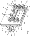
- Each sucker 32 has a sealing lip 34 which extends annularly around the end of a suction pipe 36 which runs axially inside a rod 38 which fixes the sucker 32 to the marking frame 30.
- the suckers 32 are subdivided into a first group of suckers 32a and a second group of suckers 32b.
- the first group of suckers 32a is formed by the two suckers 32 which are arranged lowest on the marking frame 30, at the two sides of the marking opening 33.
- the second group of suckers 32b comprises all the other suckers 32.
- the suction pipes 36 of the suckers 32a of the first group are in communication with a first common collector pipe 40a which is provided in the marking frame 30.
- the suction pipes 36 of the suckers 32b of the second group are in turn in communication with a second common collector pipe 40b which is also provided in the marking frame 30.
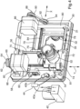
- the two collector pipes 40a, 40b communicate with a vacuum pump 42, which is illustrated in Figure 4 , with, for example, a selector 44 with manual or automatic actuation being interposed and providing for selectively carrying out a pressure reduction in the single first common collector pipe 40a or in both the common collector pipes 40a, 40b.
- the motor 60 has a drive shaft 62, on which there is keyed a drive pulley 64 which extends through a belt 66 which controls in terms of rotation a driven pulley (not visible in the Figures) which is fixed to the upper end of the manoeuvring screw 58.
- the motor 60 is mounted on a bracket 68 which projects from an upper support 70, to which there is fixed the upper end of the guide bar 56.
- the lower end of the guide bar 56 is in turn fixed to a lower support 72.
- the motor 86 has a drive shaft 88, on which there is keyed a drive pulley 90 which extends through a belt 92 which controls in terms of rotation a driven pulley 94 which is fixed to an end of the manoeuvring screw 84 which projects from the support 80.
- the motor 86 is fixed to the marking frame 30, for example, by means of a rod 87.
- the motors 60 and 86 are connected to the on-board electronic unit in known manner by means of electrical conductors (not illustrated).
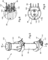
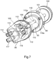
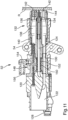
- the upper cylindrical member 101 is closed by a cap 102.
- a perforation tip 103 for the recharging cartridge projects centrally.
- openings 104 are formed around the tip 103 openings 104, through which the abrasive product which is contained in the recharging cartridge received in the upper cylindrical member 101 can descend into a collection chamber 105 which is formed in the upper support block 98 and from there into the cylindrical chamber 100.
- a system for dispensing abrasive which comprises a dispensing tube 115 which extends axially over the entire length of the main chamber 100.
- the dispensing tube 115 communicates in the lower portion with a dispensing pipe 116 which is formed in the lower support member 96 and which opens in a dispensing opening 117 which is arranged beside the opening 114 for the compressed air.
- the upper end 115a of the dispensing tube 115 is inserted in a slot 118 which is formed in the upper support block 98.
- the upper end 115a of the dispensing tube 115 is spaced apart from the bottom of the slot 118 which communicates with the main chamber 100 of the tank 13 through a series of peripheral channels 118a which are distributed radially around the dispensing tube 115.
- a small hole 119 Near the bottom of the main chamber 100, on the wall of the dispensing tube 115, there is formed a small hole 119, through which the abrasive can be introduced inside the dispensing tube 115 in order to be transported into the dispensing tube 116 by the flow of compressed air which is introduced from the main chamber 100 into the dispensing tube 115 through the upper end 115a thereof. It is possible to provide a regulator for the pressure at the outlet in order to ensure the uniformity of dispensing of the air/abrasive admixture.
- the opening 126 is connected with a tubing (not illustrated) to the dispensing opening 117 of the dispensing tank 13.
- a tubing not illustrated
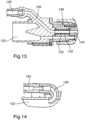
- the axial pipe 124 extends into a marking nozzle 134 which is mounted to be removable so as to be readily able to be replaced after a given number of activations of the apparatus 1 in order to ensure continuity in the precision of the marking.
- the marking nozzle 134 projects from a front opening 136 of the tubular member 120 in which there is mounted a support member 138 which is urged forwards by a spring 140.
- the support member 138 can resiliently return into the front opening 136 by a given amount so as also to adapt to the formation of the surface R in the case of marked curvature thereof, such as, for example, in the case of the headlights of the vehicles.
- the bearings are supported by a support disc 144 which is fixed to the end of the support member 138.
- shut-off valve 148 which upon command provides for the axial pipe 124 to be closed, preventing the supply of abrasive material to the nozzle 134.
- the shut-off valve 148 is of the type with a resilient sleeve and particularly comprises a compressible sleeve 150.
- the external surface of the sleeve 150 defines a wall of a control chamber 152, in which a pipe 154 which is connected to a pneumatic control circuit by means of an opening 156 opens.
- the sleeve 150 When the control chamber 152 is pressurized by supplying compressed air in the pipe 154, the sleeve becomes compressed, closing the axial passage thereof and therefore interrupting the continuity of the axial pipe 124. Conversely, by removing the pressure from the control chamber 152, the resilience of the sleeve 150 extends it radially, opening the axial passage thereof and restoring the continuity of the axial pipe 124.
- the marking process comprises three main steps:
- the operator When the operator has carried out the selections, there can be shown on video a stylized shape of the car, on which it is indicated where to position the marking head 8 in order to be able to carry out the first marking. Therefore, the operator holds the marking head 8, supports it in the position indicated on the surface R to be marked, for example, the plate glass of a vehicle, and activates the push-button 15 for activating the marking.
- the activation of the push-button 15 activates the suction group 3. If the marking head 8 is correctly supported on the surface R to be marked, the sensor associated with the U-shaped pipe 158 in the marking group provides a first permission signal. The activation of the push-button 15 further activates the vacuum pump 42 for the adhesion of the suckers 32 to the surface R to be marked. In accordance with the type of surface to be marked, there are activated all the suckers 32 or, if the surface to be marked is small, as in the case of headlights or optical groups of a vehicle, only the suckers of the first group 32a are activated. As indicated above, the selection of the suckers to be activated can be carried out manually by the operator or automatically by the equipment 1.
Landscapes
- Engineering & Computer Science (AREA)
- General Engineering & Computer Science (AREA)
- Mechanical Engineering (AREA)
- Coating Apparatus (AREA)
- Wrappers (AREA)
- Details Or Accessories Of Spraying Plant Or Apparatus (AREA)
Claims (10)
- Vorrichtung zum Markieren von Oberflächen durch Abrieb, umfassend eine Abgabegruppe (13) für einen Luft- und Schleifmittelstrom, der zu einer Markierdüse (134) gefördert wird, die an einem Markierkopf (8) mit einem selektiven Absperrventil (148) für den Luft- und Schleifmittelstrom beweglich montiert ist, und eine Steuerungsgruppe (11), die eingerichtet ist zum Steuern des wahlweisen Öffnens und Schließens des Absperrventils (148),
dadurch gekennzeichnet, dass
die Steuerungsgruppe (11) eingerichtet ist zum Steuern der Bewegung der Markierdüse (134) bezüglich des Markierkopfs (8) in einer Markierungsebene (X, Y), die im Wesentlichen quer zu einer Abgaberichtung des Luft- und Schleifmittelgemisches aus der Markierungsdüse (134) verläuft, auf einer zu markierenden Oberfläche (R). - Vorrichtung zum Markieren von Oberflächen nach Anspruch 1, wobei die Markierdüse montiert ist an einem System aus mindestens zwei Schlitten (54, 76), die mittels jeweiliger motorisierter Getriebe (56, 58, 60, 64, 66; 78, 79, 84, 86, 90, 92, 94), die durch die Steuerungsgruppe (11) gesteuert werden, in der Markierungsebene in zwei zueinander orthogonalen Richtungen (X, Y) translatorisch bewegbar sind.
- Vorrichtung zum Markieren von Oberflächen nach Anspruch 1 oder 2, wobei der Markierkopf (8) mehrere Sauger (32) aufweist, die saugtechnisch selektiv gesteuert werden, um den Markierkopf (8) an der zu markierenden Oberfläche (R) festzulegen.
- Vorrichtung zum Markieren von Oberflächen nach Anspruch 3, wobei die Sauger (32) über zwei Wechselschaltungen, die jeweils mit einer ersten Saugergruppe (32a) und einer zweiten Saugergruppe (32b) verbunden sind, mit einer Vakuumpumpe verbunden sind, wobei ein Selektor die Aktivierung der Saugleistung alternierend an den Saugern der ersten Saugergruppe (32a) und/oder an den Saugern des zweiten Saugergruppe (32b) ermöglicht.
- Vorrichtung zum Markieren von Oberflächen nach einem der vorangehenden Ansprüche, wobei die Markierdüse (134) und das Absperrventil (148) an einer beweglichen Markiergruppe (52) in der Markierungsebene (X, Y) montiert sind, umfassend einen Kopf (132), der bestimmungsgemäß an der zu markierenden Oberfläche (R) abgestützt wird, wobei der Kopf (132) federnde Elemente (140, 142) aufweist, um an die Formationen der zu markierenden Oberfläche (R) angepasst zu werden, wobei eine Sauggruppe (3) mit der Markiergruppe (52) verbunden ist, um das von der Markierdüse (134) abgegebene Schleifmittel während des Markierens der Oberfläche (R) anzusaugen.
- Vorrichtung zum Markieren von Oberflächen nach Anspruch 5, wobei die federnden Elemente umfassen:- selbstausrichtende Lager (142), die relativ komprimierbar sind und am Ende des Kopfs (132) zur Abstützung gegen die zu markierende Oberfläche (R) angeordnet sind, und/oder- federnde Einrichtungen (140), die einen federnden Druck auf ein einziehbares Stützelement (138) ausüben, an dem die Markierdüse (134) befestigt ist.
- Vorrichtung zum Markieren von Oberflächen nach einem der vorangehenden Ansprüche, wobei das Absperrventil (148) ein Muffenventil (150) ist, das in der Nähe der Markierdüse (134) montiert ist.
- Vorrichtung zum Markieren von Oberflächen nach einem der vorangehenden Ansprüche, wobei die Abgabegruppe (13) für einen Luft- und Schleifmittelstrom einen Schleifmittelbehälter umfasst, der von einer austauschbaren Schleifmittelkartusche versorgt wird.
- Vorrichtung zum Markieren von Oberflächen nach einem der vorangehenden Ansprüche, wobei die Schleifmittelabgabegruppe (13) eine Detektionseinrichtung (107) für eine Mindestmenge an für die Markierung verfügbarem Schleifmittel umfasst.
- Verfahren zum Markieren von Oberflächen mittels einer Vorrichtung nach einem der vorangehenden Ansprüche, umfassend die Schritte:- Autorisierung der Markierung durch Übermittlung einer Markierungsanforderung an einen entfernten Knoten und Empfang einer Autorisierung, die Markierungsdaten enthält, die von der Steuerungsgruppe (11) verarbeitet werden können, um Anweisungen zur Markierung an die Vorrichtung (1) zu übermitteln;- Durchführen der Markierung auf einer Oberfläche (R) durch Verbinden des Markierungskopfs (8) der Vorrichtung (1) mit der Oberfläche und Steuern des Öffnens und Schließens des Absperrventils (148) für den Luft- und Schleifmittelstrom und die Bewegung der Markierdüse (134) relativ zu dem Markierkopf (8) gemäß einer oder mehrerer durch die Markierdaten definierten Bahnen;- Deaktivieren der Abgabe von Luft und Schleifmittel an dem durch die Markierdaten definierten Ende der Markierung und- Lösen des Markierkopfs (8) von der Oberfläche (R).
Priority Applications (1)
| Application Number | Priority Date | Filing Date | Title |
|---|---|---|---|
| SM20240378T SMT202400378T1 (it) | 2020-05-20 | 2021-05-19 | Apparecchiatura e processo di marcatura di superfici per abrasione |
Applications Claiming Priority (2)
| Application Number | Priority Date | Filing Date | Title |
|---|---|---|---|
| IT102020000011674A IT202000011674A1 (it) | 2020-05-20 | 2020-05-20 | Apparecchiatura e processo di marcatura di superfici per abrasione |
| PCT/IB2021/054305 WO2021234590A2 (en) | 2020-05-20 | 2021-05-19 | Apparatus and process for marking surfaces by abrasion |
Publications (3)
| Publication Number | Publication Date |
|---|---|
| EP4153379A2 EP4153379A2 (de) | 2023-03-29 |
| EP4153379B1 true EP4153379B1 (de) | 2024-07-03 |
| EP4153379C0 EP4153379C0 (de) | 2024-07-03 |
Family
ID=71994905
Family Applications (1)
| Application Number | Title | Priority Date | Filing Date |
|---|---|---|---|
| EP21733855.7A Active EP4153379B1 (de) | 2020-05-20 | 2021-05-19 | Vorrichtung und verfahren zur markierung von oberflächen durch abrieb |
Country Status (5)
| Country | Link |
|---|---|
| EP (1) | EP4153379B1 (de) |
| ES (1) | ES2991328T3 (de) |
| IT (1) | IT202000011674A1 (de) |
| SM (1) | SMT202400378T1 (de) |
| WO (1) | WO2021234590A2 (de) |
Families Citing this family (1)
| Publication number | Priority date | Publication date | Assignee | Title |
|---|---|---|---|---|
| CN117408049B (zh) * | 2023-10-19 | 2024-04-09 | 无锡斯帝尔科技有限公司 | 一种基于3d视觉的打磨路径规划方法 |
Family Cites Families (5)
| Publication number | Priority date | Publication date | Assignee | Title |
|---|---|---|---|---|
| BE519986A (de) * | 1953-05-15 | 1953-05-30 | ||
| US3873769A (en) * | 1973-09-10 | 1975-03-25 | William L Cotter | Automatic drawing system |
| US4708534A (en) * | 1983-09-30 | 1987-11-24 | Airsonics License Partnership | Particle feed device with reserve supply |
| US5461407A (en) * | 1992-09-02 | 1995-10-24 | Telesis Marking Systems, Inc. | Marking method and apparatus using gas entrained abrasive particles |
| JPH10329890A (ja) * | 1997-05-30 | 1998-12-15 | Koei:Kk | 粉粒体供給装置 |
-
2020
- 2020-05-20 IT IT102020000011674A patent/IT202000011674A1/it unknown
-
2021
- 2021-05-19 ES ES21733855T patent/ES2991328T3/es active Active
- 2021-05-19 SM SM20240378T patent/SMT202400378T1/it unknown
- 2021-05-19 EP EP21733855.7A patent/EP4153379B1/de active Active
- 2021-05-19 WO PCT/IB2021/054305 patent/WO2021234590A2/en not_active Ceased
Also Published As
| Publication number | Publication date |
|---|---|
| SMT202400378T1 (it) | 2024-11-15 |
| EP4153379A2 (de) | 2023-03-29 |
| IT202000011674A1 (it) | 2021-11-20 |
| ES2991328T3 (es) | 2024-12-03 |
| WO2021234590A3 (en) | 2022-02-10 |
| EP4153379C0 (de) | 2024-07-03 |
| WO2021234590A2 (en) | 2021-11-25 |
Similar Documents
| Publication | Publication Date | Title |
|---|---|---|
| KR102323952B1 (ko) | 카트리지 용기, 카트리지 시스템, 음료 제조기, 및 음료를 제조하기 위한 방법 | |
| EP4153379B1 (de) | Vorrichtung und verfahren zur markierung von oberflächen durch abrieb | |
| JP4960477B2 (ja) | ワイパーブレード用警報装置、その作動方法及び警報装置を備えるワイパーブレード | |
| EP2734096B1 (de) | Spender mit optischem eingabesystem | |
| EP1007366B1 (de) | Verfahren und vorrichtung zur sicherung eines tintenbehälters | |
| EP4094661A3 (de) | Extraktionsreiniger | |
| US5497914A (en) | Car care self-service device | |
| EP0885731B1 (de) | Aufzeichnungsgerät und sein Steuerverfahren | |
| EP1654160A2 (de) | Vorrichtung zum nachfüllen von tintenstrahlpatronen und verfahren dafür | |
| US20050247141A1 (en) | Pipette | |
| US7059720B2 (en) | Ophthalmoscope | |
| US5997120A (en) | Recording apparatus which allows ink amount detection upon exchange of a printhead | |
| US7422386B2 (en) | Image creation and cutting apparatus | |
| US11072225B2 (en) | Filter apparatus for a motor vehicle, and method for operating such a filter apparatus | |
| US7354211B2 (en) | Perforation forming mechanism for use in an imaging apparatus | |
| US6973433B2 (en) | Franking machine | |
| EP0818315A1 (de) | Zum Abdichten geeigneter Druckkopf für einen Tintenstrahldrucker | |
| CN102673186A (zh) | 打印机的控制方法以及打印机 | |
| US6983137B2 (en) | Electronic apparatus, drive mechanism and drive control method for a front panel | |
| US20040263588A1 (en) | Apparatus and method for refurbishing used cartridges for ink jet type imaging devices | |
| CN109501715B (zh) | 打开或启动车辆的钥匙装置和清洁车辆外部元件的方法 | |
| JP2018183981A (ja) | 印刷前に3次元物体に複数の表面処理を提供するプリンタおよびプリンタを作動する方法 | |
| KR101909542B1 (ko) | 면도날 연마기능을 구비하는 면도기 거치대 | |
| JP3327747B2 (ja) | インクジェット記録装置 | |
| KR100819178B1 (ko) | 내면수퍼피니싱장치 및 그 제어시스템 |
Legal Events
| Date | Code | Title | Description |
|---|---|---|---|
| STAA | Information on the status of an ep patent application or granted ep patent |
Free format text: STATUS: UNKNOWN |
|
| STAA | Information on the status of an ep patent application or granted ep patent |
Free format text: STATUS: THE INTERNATIONAL PUBLICATION HAS BEEN MADE |
|
| PUAI | Public reference made under article 153(3) epc to a published international application that has entered the european phase |
Free format text: ORIGINAL CODE: 0009012 |
|
| STAA | Information on the status of an ep patent application or granted ep patent |
Free format text: STATUS: REQUEST FOR EXAMINATION WAS MADE |
|
| 17P | Request for examination filed |
Effective date: 20221003 |
|
| AK | Designated contracting states |
Kind code of ref document: A2 Designated state(s): AL AT BE BG CH CY CZ DE DK EE ES FI FR GB GR HR HU IE IS IT LI LT LU LV MC MK MT NL NO PL PT RO RS SE SI SK SM TR |
|
| P01 | Opt-out of the competence of the unified patent court (upc) registered |
Effective date: 20230626 |
|
| DAV | Request for validation of the european patent (deleted) | ||
| DAX | Request for extension of the european patent (deleted) | ||
| RIC1 | Information provided on ipc code assigned before grant |
Ipc: B24C 7/00 20060101ALN20231214BHEP Ipc: B24C 5/02 20060101ALN20231214BHEP Ipc: B24C 3/06 20060101ALN20231214BHEP Ipc: B44B 3/00 20060101ALI20231214BHEP Ipc: B44C 1/22 20060101ALI20231214BHEP Ipc: B24C 1/04 20060101AFI20231214BHEP |
|
| GRAP | Despatch of communication of intention to grant a patent |
Free format text: ORIGINAL CODE: EPIDOSNIGR1 |
|
| STAA | Information on the status of an ep patent application or granted ep patent |
Free format text: STATUS: GRANT OF PATENT IS INTENDED |
|
| INTG | Intention to grant announced |
Effective date: 20240124 |
|
| RIC1 | Information provided on ipc code assigned before grant |
Ipc: B24C 7/00 20060101ALN20240112BHEP Ipc: B24C 5/02 20060101ALN20240112BHEP Ipc: B24C 3/06 20060101ALN20240112BHEP Ipc: B44B 3/00 20060101ALI20240112BHEP Ipc: B44C 1/22 20060101ALI20240112BHEP Ipc: B24C 1/04 20060101AFI20240112BHEP |
|
| GRAS | Grant fee paid |
Free format text: ORIGINAL CODE: EPIDOSNIGR3 |
|
| GRAA | (expected) grant |
Free format text: ORIGINAL CODE: 0009210 |
|
| STAA | Information on the status of an ep patent application or granted ep patent |
Free format text: STATUS: THE PATENT HAS BEEN GRANTED |
|
| AK | Designated contracting states |
Kind code of ref document: B1 Designated state(s): AL AT BE BG CH CY CZ DE DK EE ES FI FR GB GR HR HU IE IS IT LI LT LU LV MC MK MT NL NO PL PT RO RS SE SI SK SM TR |
|
| REG | Reference to a national code |
Ref country code: CH Ref legal event code: EP |
|
| REG | Reference to a national code |
Ref country code: DE Ref legal event code: R096 Ref document number: 602021015208 Country of ref document: DE |
|
| U01 | Request for unitary effect filed |
Effective date: 20240801 |
|
| P04 | Withdrawal of opt-out of the competence of the unified patent court (upc) registered |
Free format text: CASE NUMBER: APP_48688/2024 Effective date: 20240826 |
|
| U07 | Unitary effect registered |
Designated state(s): AT BE BG DE DK EE FI FR IT LT LU LV MT NL PT RO SE SI Effective date: 20240902 |
|
| REG | Reference to a national code |
Ref country code: ES Ref legal event code: FG2A Ref document number: 2991328 Country of ref document: ES Kind code of ref document: T3 Effective date: 20241203 |
|
| P05 | Withdrawal of opt-out of the competence of the unified patent court (upc) changed |
Free format text: CASE NUMBER: APP_48688/2024 Effective date: 20240902 |
|
| PG25 | Lapsed in a contracting state [announced via postgrant information from national office to epo] |
Ref country code: NO Free format text: LAPSE BECAUSE OF FAILURE TO SUBMIT A TRANSLATION OF THE DESCRIPTION OR TO PAY THE FEE WITHIN THE PRESCRIBED TIME-LIMIT Effective date: 20241003 |
|
| PG25 | Lapsed in a contracting state [announced via postgrant information from national office to epo] |
Ref country code: GR Free format text: LAPSE BECAUSE OF FAILURE TO SUBMIT A TRANSLATION OF THE DESCRIPTION OR TO PAY THE FEE WITHIN THE PRESCRIBED TIME-LIMIT Effective date: 20241004 Ref country code: PL Free format text: LAPSE BECAUSE OF FAILURE TO SUBMIT A TRANSLATION OF THE DESCRIPTION OR TO PAY THE FEE WITHIN THE PRESCRIBED TIME-LIMIT Effective date: 20240703 |
|
| PG25 | Lapsed in a contracting state [announced via postgrant information from national office to epo] |
Ref country code: IS Free format text: LAPSE BECAUSE OF FAILURE TO SUBMIT A TRANSLATION OF THE DESCRIPTION OR TO PAY THE FEE WITHIN THE PRESCRIBED TIME-LIMIT Effective date: 20241103 |
|
| PG25 | Lapsed in a contracting state [announced via postgrant information from national office to epo] |
Ref country code: HR Free format text: LAPSE BECAUSE OF FAILURE TO SUBMIT A TRANSLATION OF THE DESCRIPTION OR TO PAY THE FEE WITHIN THE PRESCRIBED TIME-LIMIT Effective date: 20240703 Ref country code: CZ Free format text: LAPSE BECAUSE OF FAILURE TO SUBMIT A TRANSLATION OF THE DESCRIPTION OR TO PAY THE FEE WITHIN THE PRESCRIBED TIME-LIMIT Effective date: 20240703 |
|
| PG25 | Lapsed in a contracting state [announced via postgrant information from national office to epo] |
Ref country code: RS Free format text: LAPSE BECAUSE OF FAILURE TO SUBMIT A TRANSLATION OF THE DESCRIPTION OR TO PAY THE FEE WITHIN THE PRESCRIBED TIME-LIMIT Effective date: 20241003 |
|
| PG25 | Lapsed in a contracting state [announced via postgrant information from national office to epo] |
Ref country code: RS Free format text: LAPSE BECAUSE OF FAILURE TO SUBMIT A TRANSLATION OF THE DESCRIPTION OR TO PAY THE FEE WITHIN THE PRESCRIBED TIME-LIMIT Effective date: 20241003 Ref country code: PL Free format text: LAPSE BECAUSE OF FAILURE TO SUBMIT A TRANSLATION OF THE DESCRIPTION OR TO PAY THE FEE WITHIN THE PRESCRIBED TIME-LIMIT Effective date: 20240703 Ref country code: NO Free format text: LAPSE BECAUSE OF FAILURE TO SUBMIT A TRANSLATION OF THE DESCRIPTION OR TO PAY THE FEE WITHIN THE PRESCRIBED TIME-LIMIT Effective date: 20241003 Ref country code: IS Free format text: LAPSE BECAUSE OF FAILURE TO SUBMIT A TRANSLATION OF THE DESCRIPTION OR TO PAY THE FEE WITHIN THE PRESCRIBED TIME-LIMIT Effective date: 20241103 Ref country code: HR Free format text: LAPSE BECAUSE OF FAILURE TO SUBMIT A TRANSLATION OF THE DESCRIPTION OR TO PAY THE FEE WITHIN THE PRESCRIBED TIME-LIMIT Effective date: 20240703 Ref country code: GR Free format text: LAPSE BECAUSE OF FAILURE TO SUBMIT A TRANSLATION OF THE DESCRIPTION OR TO PAY THE FEE WITHIN THE PRESCRIBED TIME-LIMIT Effective date: 20241004 Ref country code: CZ Free format text: LAPSE BECAUSE OF FAILURE TO SUBMIT A TRANSLATION OF THE DESCRIPTION OR TO PAY THE FEE WITHIN THE PRESCRIBED TIME-LIMIT Effective date: 20240703 |
|
| PG25 | Lapsed in a contracting state [announced via postgrant information from national office to epo] |
Ref country code: SK Free format text: LAPSE BECAUSE OF FAILURE TO SUBMIT A TRANSLATION OF THE DESCRIPTION OR TO PAY THE FEE WITHIN THE PRESCRIBED TIME-LIMIT Effective date: 20240703 |
|
| PLBE | No opposition filed within time limit |
Free format text: ORIGINAL CODE: 0009261 |
|
| STAA | Information on the status of an ep patent application or granted ep patent |
Free format text: STATUS: NO OPPOSITION FILED WITHIN TIME LIMIT |
|
| 26N | No opposition filed |
Effective date: 20250404 |
|
| U20 | Renewal fee for the european patent with unitary effect paid |
Year of fee payment: 5 Effective date: 20250528 |
|
| PGFP | Annual fee paid to national office [announced via postgrant information from national office to epo] |
Ref country code: SM Payment date: 20250423 Year of fee payment: 5 |
|
| PGFP | Annual fee paid to national office [announced via postgrant information from national office to epo] |
Ref country code: GB Payment date: 20250527 Year of fee payment: 5 |
|
| PGFP | Annual fee paid to national office [announced via postgrant information from national office to epo] |
Ref country code: CH Payment date: 20250601 Year of fee payment: 5 |
|
| PGFP | Annual fee paid to national office [announced via postgrant information from national office to epo] |
Ref country code: IE Payment date: 20250521 Year of fee payment: 5 |
|
| PGFP | Annual fee paid to national office [announced via postgrant information from national office to epo] |
Ref country code: ES Payment date: 20250630 Year of fee payment: 5 |
|
| PG25 | Lapsed in a contracting state [announced via postgrant information from national office to epo] |
Ref country code: MC Free format text: LAPSE BECAUSE OF FAILURE TO SUBMIT A TRANSLATION OF THE DESCRIPTION OR TO PAY THE FEE WITHIN THE PRESCRIBED TIME-LIMIT Effective date: 20240703 |