EP4153377B1 - Laserschweissverfahren - Google Patents
Laserschweissverfahren Download PDFInfo
- Publication number
- EP4153377B1 EP4153377B1 EP21729110.3A EP21729110A EP4153377B1 EP 4153377 B1 EP4153377 B1 EP 4153377B1 EP 21729110 A EP21729110 A EP 21729110A EP 4153377 B1 EP4153377 B1 EP 4153377B1
- Authority
- EP
- European Patent Office
- Prior art keywords
- power
- annular
- center
- welding method
- laser welding
- Prior art date
- Legal status (The legal status is an assumption and is not a legal conclusion. Google has not performed a legal analysis and makes no representation as to the accuracy of the status listed.)
- Active
Links
Images


Classifications
-
- B—PERFORMING OPERATIONS; TRANSPORTING
- B23—MACHINE TOOLS; METAL-WORKING NOT OTHERWISE PROVIDED FOR
- B23K—SOLDERING OR UNSOLDERING; WELDING; CLADDING OR PLATING BY SOLDERING OR WELDING; CUTTING BY APPLYING HEAT LOCALLY, e.g. FLAME CUTTING; WORKING BY LASER BEAM
- B23K26/00—Working by laser beam, e.g. welding, cutting or boring
- B23K26/20—Bonding
- B23K26/21—Bonding by welding
- B23K26/24—Seam welding
- B23K26/244—Overlap seam welding
-
- B—PERFORMING OPERATIONS; TRANSPORTING
- B23—MACHINE TOOLS; METAL-WORKING NOT OTHERWISE PROVIDED FOR
- B23K—SOLDERING OR UNSOLDERING; WELDING; CLADDING OR PLATING BY SOLDERING OR WELDING; CUTTING BY APPLYING HEAT LOCALLY, e.g. FLAME CUTTING; WORKING BY LASER BEAM
- B23K26/00—Working by laser beam, e.g. welding, cutting or boring
- B23K26/02—Positioning or observing the workpiece, e.g. with respect to the point of impact; Aligning, aiming or focusing the laser beam
- B23K26/06—Shaping the laser beam, e.g. by masks or multi-focusing
- B23K26/0604—Shaping the laser beam, e.g. by masks or multi-focusing by a combination of beams
- B23K26/0613—Shaping the laser beam, e.g. by masks or multi-focusing by a combination of beams having a common axis
-
- B—PERFORMING OPERATIONS; TRANSPORTING
- B23—MACHINE TOOLS; METAL-WORKING NOT OTHERWISE PROVIDED FOR
- B23K—SOLDERING OR UNSOLDERING; WELDING; CLADDING OR PLATING BY SOLDERING OR WELDING; CUTTING BY APPLYING HEAT LOCALLY, e.g. FLAME CUTTING; WORKING BY LASER BEAM
- B23K26/00—Working by laser beam, e.g. welding, cutting or boring
- B23K26/02—Positioning or observing the workpiece, e.g. with respect to the point of impact; Aligning, aiming or focusing the laser beam
- B23K26/06—Shaping the laser beam, e.g. by masks or multi-focusing
- B23K26/062—Shaping the laser beam, e.g. by masks or multi-focusing by direct control of the laser beam
- B23K26/0622—Shaping the laser beam, e.g. by masks or multi-focusing by direct control of the laser beam by shaping pulses
-
- B—PERFORMING OPERATIONS; TRANSPORTING
- B23—MACHINE TOOLS; METAL-WORKING NOT OTHERWISE PROVIDED FOR
- B23K—SOLDERING OR UNSOLDERING; WELDING; CLADDING OR PLATING BY SOLDERING OR WELDING; CUTTING BY APPLYING HEAT LOCALLY, e.g. FLAME CUTTING; WORKING BY LASER BEAM
- B23K26/00—Working by laser beam, e.g. welding, cutting or boring
- B23K26/02—Positioning or observing the workpiece, e.g. with respect to the point of impact; Aligning, aiming or focusing the laser beam
- B23K26/06—Shaping the laser beam, e.g. by masks or multi-focusing
- B23K26/062—Shaping the laser beam, e.g. by masks or multi-focusing by direct control of the laser beam
- B23K26/0626—Energy control of the laser beam
-
- B—PERFORMING OPERATIONS; TRANSPORTING
- B23—MACHINE TOOLS; METAL-WORKING NOT OTHERWISE PROVIDED FOR
- B23K—SOLDERING OR UNSOLDERING; WELDING; CLADDING OR PLATING BY SOLDERING OR WELDING; CUTTING BY APPLYING HEAT LOCALLY, e.g. FLAME CUTTING; WORKING BY LASER BEAM
- B23K26/00—Working by laser beam, e.g. welding, cutting or boring
- B23K26/02—Positioning or observing the workpiece, e.g. with respect to the point of impact; Aligning, aiming or focusing the laser beam
- B23K26/06—Shaping the laser beam, e.g. by masks or multi-focusing
- B23K26/064—Shaping the laser beam, e.g. by masks or multi-focusing by means of optical elements, e.g. lenses, mirrors or prisms
- B23K26/0648—Shaping the laser beam, e.g. by masks or multi-focusing by means of optical elements, e.g. lenses, mirrors or prisms comprising lenses
-
- B—PERFORMING OPERATIONS; TRANSPORTING
- B23—MACHINE TOOLS; METAL-WORKING NOT OTHERWISE PROVIDED FOR
- B23K—SOLDERING OR UNSOLDERING; WELDING; CLADDING OR PLATING BY SOLDERING OR WELDING; CUTTING BY APPLYING HEAT LOCALLY, e.g. FLAME CUTTING; WORKING BY LASER BEAM
- B23K26/00—Working by laser beam, e.g. welding, cutting or boring
- B23K26/02—Positioning or observing the workpiece, e.g. with respect to the point of impact; Aligning, aiming or focusing the laser beam
- B23K26/06—Shaping the laser beam, e.g. by masks or multi-focusing
- B23K26/0665—Shaping the laser beam, e.g. by masks or multi-focusing by beam condensation on the workpiece, e.g. for focusing
-
- B—PERFORMING OPERATIONS; TRANSPORTING
- B23—MACHINE TOOLS; METAL-WORKING NOT OTHERWISE PROVIDED FOR
- B23K—SOLDERING OR UNSOLDERING; WELDING; CLADDING OR PLATING BY SOLDERING OR WELDING; CUTTING BY APPLYING HEAT LOCALLY, e.g. FLAME CUTTING; WORKING BY LASER BEAM
- B23K26/00—Working by laser beam, e.g. welding, cutting or boring
- B23K26/02—Positioning or observing the workpiece, e.g. with respect to the point of impact; Aligning, aiming or focusing the laser beam
- B23K26/06—Shaping the laser beam, e.g. by masks or multi-focusing
- B23K26/073—Shaping the laser spot
- B23K26/0734—Shaping the laser spot into an annular shape
-
- B—PERFORMING OPERATIONS; TRANSPORTING
- B23—MACHINE TOOLS; METAL-WORKING NOT OTHERWISE PROVIDED FOR
- B23K—SOLDERING OR UNSOLDERING; WELDING; CLADDING OR PLATING BY SOLDERING OR WELDING; CUTTING BY APPLYING HEAT LOCALLY, e.g. FLAME CUTTING; WORKING BY LASER BEAM
- B23K2103/00—Materials to be soldered, welded or cut
- B23K2103/02—Iron or ferrous alloys
- B23K2103/04—Steel or steel alloys
Definitions
- the present invention relates in general to welding using focused beams of laser radiation.
- the invention relates in particular to welding metal alloys using a focused center beam and a focused annular beam.
- Beams of laser radiation are increasingly used for cutting, drilling, welding, marking, and scribing workpieces made of a wide range of materials; including metals and metal alloys.
- Traditional mechanical processing produces unwanted defects, such as micro-cracks that may propagate when a processed workpiece is stressed, thereby degrading and weakening the processed workpiece.
- Laser processing minimizes such unwanted defects, is generally cleaner, and causes a smaller heat-affected zone.
- Laser machining uses a focused laser beam to produce precise cuts and holes, having high-quality edges and walls, while minimizing the formation of unwanted defects.
- a focused laser beam locates each weld spot or line precisely, while minimizing collateral heating. It is useful to distinguish two main laser welding regimes.
- Conduction welding occurs at lower laser powers and lower power densities. Absorbed laser power heats the irradiated material, melting material in each part to be joined, which flows, mixes, and then solidifies.
- Keyhole welding occurs at higher laser powers and higher power densities that are sufficient to vaporize some of the irradiated material. Pressure of the vaporized material on surrounding melted material opens a channel through the melted material, having a characteristic narrow and deep profile, which allows deep penetration of the laser beam. Finished keyhole welds are generally narrower, deeper, and stronger than conduction welds. However, it can be difficult to maintain a stable keyhole in a hot and dynamic pool of melted material.
- One problem when laser welding some metals and metal alloys is the formation of defects, particularly cracks, at the termination of a line weld. Some defects are caused by stress that is induced while the workpiece is cooling. These initial defects weaken a welded workpiece and may further propagate if thermal or mechanical stress is applied when the finished workpiece is put to use. An unreliable weld in a structure could lead to catastrophic failure.
- One known solution to mitigate defects is to rapidly reduce the laser power at the termination of a weld, rather than switching off the power digitally.
- Another known solution is to rapidly lift the focused beam at the termination of a weld, thereby illuminating a progressively larger area on the workpiece with a progressively lower intensity beam.
- the power of the center beam is then ramped down. While this method works well to prevent defects, the focused laser beam is moving across the surface of the workpiece during these power changes, producing a gradual taper in the width of the weld. This taper is typically a few millimeters long and is unacceptable in some applications that require a uniform cross section along the whole length of the weld. The very end of the weld can also taper in depth.
- US patent application with publication No. US2018/147661 discloses at a first laser device, providing a first optical feed fiber and a second laser device providing a second optical feed fiber.
- a beam combining means connected to the first and second feed fibers and to a multi-core optical fiber is adapted to form a composite laser beam by having the first optical feed fiber aligned with a first core of the multi-core optical fiber and the second optical feed fiber aligned with at least one second core of the multi-core optical fiber.
- the first and second cores outputs a composite laser beam to a workpiece to be processed.
- a control unit individually controls the power density of the output laser beams.
- welds having uniform cross sections in metals and metal alloys that are prone to cracking at the termination of a weld.
- the process would not compromise any of the advantages of laser welding, such as weld speed, precision, weld quality, and cost-per-weld.
- a method for laser welding a workpiece along a weld line in accordance with the present invention comprises delivering a focused beam of laser radiation to the workpiece.
- the focused beam has a focused center beam and a concentric focused annular beam.
- the focused center beam is smaller than the focused annular beam on a surface of the workpiece exposed to the focused beam.
- the focused beam is moved laterally with respect to the workpiece along the weld line.
- the center beam has a center processing power and the annular beam has an annular processing power.
- the power of the annular beam is reduced from the annular processing power.
- the lateral movement of the focused beam with respect to the workpiece is stopped when the focused beam reaches an end location on the weld line.
- the power of the center beam is increased from the center processing power.
- the power of the annular beam is ramped down at a first annular ramp rate while the power of the center beam is ramped down at a first center ramp rate.
- the power of the annular beam is ramped down at a second annular ramp rate while the power of the center beam is ramped down at a second center ramp rate.
- the second annular ramp rate is less than the first annular ramp rate.
- the second center ramp rate is less than the first center ramp rate.
- FIGS 1A and 1B schematically illustrate an apparatus 10 used in prior-art laser processing methods and in the laser welding method of the present invention.
- a laser source 12 delivers at least two beams of laser radiation through an optical fiber 14 to a focusing lens 16.
- Optical fiber 14 includes a center core 32 for guiding a center beam of laser radiation. Center core 32 has a low refractive index cladding 34.
- Optical fiber 14 further includes an annular core 36 for guiding an annular beam of laser radiation. Annular core 36 is concentrically located between low refractive index cladding 34 and another low refractive index cladding 38.
- Laser source 12 is configured to deliver the center beam to center core 32 and the annular beam to annular core 36.
- Laser systems integrating such a laser source with such an optical fiber are commercially available.
- the Highlight TM FL-ARM laser from Coherent Inc. of Santa Clara, California.
- One feature of this particular laser system is that the powers of the center beam and annular beam can be adjusted independently and with high precision.
- Focusing lens 16 forms a focused beam 18, comprising a focused center beam depicted as converging solid lines and a concentric focused annular beam depicted as converging dashed lines. The focused beams converge towards a focus 20, where the focused center beam has a smaller diameter than the concentric focused annular beam.
- Apparatus 10 may also include an optional beam expander, not depicted here, located between optical fiber 14 and focusing lens 16. Focusing lens 16 is depicted here as a fiber-coupled lens assembly, which are usually arranged to allow internal expansion of beams emerging from the optical fiber, prior to focusing.
- Focused beam 18 is directed onto a workpiece 22, which initially comprises two pieces to be welded together, referred to here as the "top piece” and “bottom piece” for convenience of description. Terms such as “top” and “bottom” are not meant to imply specific spatial orientations of the workpiece.
- the two pieces of workpiece 22 may be coated or uncoated.
- the two pieces of workpiece 22 may be in direct contact or may be separated by a small gap.
- zinc coated steel is commonly welded with a gap of up to a few hundred microns to allow highpressure zinc vapor to escape.
- the two pieces are depicted in cross section during lap welding.
- Workpiece 22 is supported and moved by a translation stage 24.
- Focus 20 is depicted located close to a top surface of workpiece 22.
- the focus may be located above, on, or below the top surface.
- the focus is preferably at a depth of focus between about 1 millimeters (mm) above the surface and about 2 mm below the surface.
- translation stage 24 is moved laterally, as indicated by vector M.
- the weld is depicted as hatching on workpiece 22 and is formed along a desired weld line 26 from a beginning location 28 to an end location 30.
- Laterally moving workpiece 22 moves focused beam 18 relative to workpiece 22 along weld line 26.
- Apparatus 10 may also be configured to move focusing lens 16 and thereby move focused beam 18 with respect to workpiece 22.
- Focusing lens 16 may be an assembly that incorporates galvanometer-actuated mirrors and a flat-field objective, for rapidly moving focused beam 18 laterally with respect to workpiece 22.
- workpieces having other shapes can be welded using the inventive method. For example, molded sheet-metal parts used in automotive bodies often have complex three-dimensional shapes. Robots having multiple degrees-of-freedom can weld together molded sheet-metal parts along curvilinear weld lines.
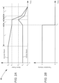
- FIGS 2A and 2B together form a timing diagram schematically illustrating one preferred embodiment of a laser welding method 40 in accordance with the present invention using apparatus 10.
- FIG. 2A is a graph of power in the annular beam and power in the center beam as a function of time.
- FIG. 2B is a graph of lateral translation velocity of the focused beam with respect to the workpiece as a function of time.
- the timing diagram spans a temporal range that includes the end of linear welding and the termination of welding.
- the focused beam is moving along weld line 26 at a constant velocity V between beginning location 28 and end location 30. For example, a constant velocity V that is between 15 and 135 millimeters per second (mm/s).
- T S the focused beam reaches the end location and stops.
- the power of the annular beam is reduced gradually from annular processing power P A to a lower power P 1 .
- This gradual reduction in power eliminates a transverse crack that would otherwise propagate to the underside of the weld and be visible on the bottom surface of the welded workpiece.
- Increasing the rate at which the power of the annular beam is reduced moves this crack towards the end location, where it will be consumed during subsequent steps of the inventive method.
- reducing the annular power also changes the cross-sectional shape of the weld, as discussed below. It is therefore preferable to reduce the power at a minimum rate sufficient to reliably eliminate the unwanted transverse crack.
- the power of the annular beam is P 1 , which is maintained through a time T 2 .
- the power of the center beam is increased from center processing power Pc to a higher power P 2 , delivering more laser power through the keyhole to the bottom side of the workpiece.
- the weld on the top side of the workpiece is broadened due to irradiation by the stationary focused annular beam. This broadening is balanced by increasing the power of the center beam to broaden the weld on the bottom side of the workpiece. The increase in power thereby prevents the formation of a weld having an asymmetrical cross-section and undesirable asymmetrical mechanical stress that would weaken the weld.
- the power of the annular beam is ramped down at a first annular ramp rate and the power of the center beam is ramped down at a first center ramp rate.
- This ramping down during T 3 provides a controlled collapse of the keyhole and is essentially a transition to conduction welding conditions around the end location. Cooling and solidification of the melted material begins during time T 3 .
- the power of the annular beam is ramped down at a second annular ramp rate and the power of the center beam is ramped down at a second center ramp rate.
- the powers of these beams are ramped down more slowly during time T 4 than time T 3 , to provide a slower and more controlled solidification of the remaining melted material.
- the second annular ramp rate is less than the first annular ramp rate and the second center ramp rate is less than the first center ramp rate.
- the power densities in the focused annular beam and the focused center beam preferably converge to provide uniform heating of the surface of the workpiece.
- the annular and center beams have been ramped down to an "off-power" P O , which means a power that is too low to melt or damage an exposed area of the workpiece.
- the off-power could be 0 watts (W).
- the inventors have found that if the focused laser beam is simply switched off or even linearly reduced in power when it reaches the end location, solidification causes significant cracking. Without laser power delivered through a keyhole, solidification starts from the bottom of the weld pool. There is fast grain growth from the sides of the weld inwards towards the center, which concentrates stress along the center of the weld line. Cooling is accompanied by shrinkage of the material that tares the weld along the weld line. In some instances, the crack that is produced can propagate along the whole weld. High-strength steels are particularly prone to this cracking along the center of the weld line and additional cracks can form around the end location.
- the inventive method prevents these defects by providing additional energy to the bottom piece through the keyhole during time T 2 , so the top and bottom pieces are close in temperature to minimize interfacial cracks that propagate to the bottom surface.
- the welded workpiece has a characteristic "bulb" shape around end location 30 (visible in FIGS 5A and 5B ).
- a bulb begins forming during time T 2 while the focused beam is stationary. Controlling the solidification and cooling by ramping down the power through times T 3 and T 4 produces slower local grain growth that minimizes crack formation at the end location. Material at the end location solidifies and cools radially inward, which concentrates stress in a small volume at the center of the bulb, instead of the center of the weld line.
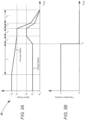
- FIGS 3A and 3B together form a timing diagram schematically illustrating another laser welding method 50 in accordance with the present invention.
- FIG. 3A is a graph of power in the annular beam and power in the center beam as a function of time.
- FIG. 3B is a graph of lateral translation velocity of the focused beam with respect to the workpiece as a function of time.
- Welding method 50 is similar to welding method 40 of FIGS 2A and 2B , but further includes a dwell time T 2' between times T 2 and T 3 , during which the power of the annular beam is maintained at about P 1 and the power of the center beam is maintained at about P 2 .
- dwell time T 2' additional energy is delivered through the keyhole by the focused center beam, which provides additional heating of the bottom piece to equalize the temperatures of the bottom piece and the top piece.
- Power P 1 , power P 2 , and dwell time T 2' may be selected to form a weld at the end location that is symmetrical in cross section.
- the bulb is symmetrical about the interface between the top piece and bottom piece, as discussed further below.
- a dwell time T 2' of tens of milliseconds (ms) is usually sufficient.
- the power of the annular beam is reduced from annular processing power P A to lower power P 1 over the total time T 1 and T 2 .
- the power of the annular beam is reduced to lower power P 1 over just time T 1 .
- This difference between the welding methods is not critical because the reduction in power of the annular beam is gradual. For example, a reduction in power of between 10% and 20%, over the last few millimeters of the weld. Time T 1 will generally be much longer than time T 2 .
- FIGS 4A and 4B together form a timing diagram schematically illustrating yet another laser welding method 60 in accordance with the present invention.
- FIG. 4A is a graph of power in the annular beam and power in the center beam as a function of time.
- FIG. 4B is a graph of lateral translation velocity of the focused beam with respect to the workpiece as a function of time.
- Welding method 60 is similar to welding method 40 of FIGS 2A and 2B , but includes an additional pulse of laser power, applied near the end of solidification of the weld pool.
- any remaining melted material in the center of the bulb solidifies and cools.
- a residual void can form near the top surface at the center of the bulb.
- residual cracks form within the bulb.
- the additional pulse of laser power in welding method 60 prevents these defects from forming by further slowing and controlling solidification of the remaining melt pool.
- the additional pulse re-melts hot material at the top surface, erasing any residual void, residual cracks, or other defects.
- the annular and center beams are maintained at the off-power during a time T 5 , following times T 3 and T 4 , while the melt pool solidifies and diminishes in volume. Then the pulse of laser power is applied during a time T 6 .
- the power of the annular beam P 3 during time T 6 is low compared to annular processing power P A and the power of the center beam P 4 during time T 6 is also low compared to center processing power P C .
- the energy applied during time T 6 is, at most, sufficient for surface re-melting and the power density is preferably uniform. Therefore, power P 4 of the smaller focused center beam is generally less than power P 3 of the focused annular beam.
- FIGS 5A and 5B are plan-view magnified photographs showing a lap weld in a high-strength steel workpiece that was made using welding method 60 of FIGS 4A and 4B , with the addition of a dwell time T 2' as in method 50 of FIGS 3A and 3B .
- the workpiece was two 1.4 mm thick pieces of galvanized Gen3 steel with a 0.3 mm gap therebetween.
- the laser system included a Highlight TM FL10000-ARM laser and a scanner mounted on a robot arm for translating the focused beam. Prior to time T S , the focused beam was translated at a velocity of 46 mm/s along the weld line, with an annular processing power P A of 3800 W and a center processing power Pc of 1000 W.
- T 1 3500 W
- P 2 1600 W
- P 3 200 W
- P 4 50 W
- T 1 100 ms
- T 2 5 ms
- T 2' 50 ms
- T 3 60 ms
- T 4 160 ms
- T 5 70 ms
- T 6 30 ms.
- FIG. 5A shows the top surface, which was exposed to the focused laser beam
- FIG. 5B shows the bottom surface.
- the focused beam was scanned from right to left along weld line 26, from beginning location 28 to end location 30.
- the weld has about uniform surface width along most of the weld line, which is approximately the diameter of the focused annular beam.
- the weld has a bulb around the end location, as discussed above. There are no cracks on the surfaces of this weld.
- the weld line is dashed in the drawings, so as not to obscure any cracking along the center of the weld.
- FIGS 6A and 6B are higher-magnification photographs of the workpiece of FIGS 5A and 5B around the bulb.
- FIG. 6A shows the top surface and
- FIG. 6B shows the bottom surface. There are no cracks apparent along the center line or within the bulb. There are no pronounced cavities or other defects near the center of the bulb.
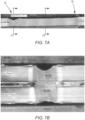
- FIGS 7A - 7C are cross-sectional magnified photographs of the workpiece of FIGS 5A and 5B .
- FIG. 7A shows the weld along the whole weld line from beginning location 28 to end location 30.
- the weld has about uniform height along most of the weld line and has no apparent discontinuities, cracks, or voids.
- the weld tapers slightly around end location 30, as discussed below.
- FIG. 7B shows the weld in cross section at a location about midway between the beginning location and the end location. This location was exposed to the focused beam prior to time T 1 , while the center beam was at center processing power Pc and the annular beam was at annular processing power P A .
- the weld has about uniform width through the workpiece or (equivalently) the weld has relatively flat walls, as desired. This means the weld is symmetrical about the interface between the two pieces.
- the weld has a meniscus in the top and bottom surfaces, which is typical of lap welding across a gap when not using a filler material.
- FIG. 7C shows the weld in cross section at the end location.
- the weld extends through the full thickness of the workpiece.
- the weld has symmetry between the top piece and bottom piece, with about the same amount of material melted in each piece. This symmetry produces a cross-sectional "butterfly" or "hourglass" shape at the end location.
- the waist located at the interface between the two pieces has about the same width (-1.8 mm) as the rest of the weld (-1.6 mm, represented by the cross section in FIG. 7B ), so the termination of the weld is not a point of weakness in the welded workpiece. There are no apparent cracks or voids at the end location.
- the bulb diameter is about 3.1 mm as measured on the top surface in this cross section.
- the inventive welding method can be applied to a variety of metal alloys.
- high-strength steel alloys “Gen3” and “XGen3”, which are third-generation steels as known in the art.
- the method can also be applied to dual-phase steels, such as "DP600” and "DP980”.
- the method can also be applied to Usibor ® and Ductibor ® branded steels, which are commercially available from ArcelorMittal S.A. of Luxembourg, Luxembourg.
- the inventive method could be applied to other configurations, such as fillet welding or butt welding.
- the method still regulates heating and then controls solidification and cooling at the bottom of the weld, which corresponds to the deepest penetration of the keyhole into the workpiece.
- the method would still mitigate crack formation and still form a characteristic bulb at the termination of the weld.
- a weld would be formed having about uniform width between the exposed surface and the bottom of the weld along most of the weld line.
Landscapes
- Physics & Mathematics (AREA)
- Optics & Photonics (AREA)
- Engineering & Computer Science (AREA)
- Plasma & Fusion (AREA)
- Mechanical Engineering (AREA)
- Laser Beam Processing (AREA)
Claims (20)
- Verfahren zum Laserschweißen eines Werkstücks (22) entlang einer Schweißlinie (26), das die folgenden Schritte beinhaltet:Zuführen eines fokussierten Strahls (18) von Laserstrahlung zu dem Werkstück (22), wobei der fokussierte Strahl (18) einen fokussierten Mittelstrahl und einen konzentrischen fokussierten Ringstrahl aufweist, wobei der fokussierte Strahl auf einer von dem fokussierten Strahl (18) bestrahlten Oberfläche des Werkstücks (22) einen kleineren Durchmesser als der fokussierte Ringstrahl aufweist;Bewegen des fokussierten Strahls (18) seitlich in Bezug auf das Werkstück (22) entlang der Schweißlinie (26), wobei der Mittelstrahl eine Mittenbearbeitungsleistung (Pc) aufweist und der Ringstrahl eine Ringbearbeitungsleistung (PA) aufweist;Verringern der Leistung des Ringstrahls von der Ringbearbeitungsleistung (PA);Anhalten der seitlichen Bewegung des fokussierten Strahls (18) in Bezug auf das Werkstück (22), wenn der fokussierte Strahl (18) eine Endposition auf der Schweißlinie (26) erreicht;Steigern der Leistung des Mittelstrahls von der Mittenbearbeitungsleistung;Absenken der Leistung des Ringstrahls mit einer ersten Ringstrahlrampenrate, während die Leistung des Mittelstrahls mit einer ersten Mittelstrahlrampenrate abgesenkt wird; undAbsenken der Leistung des Ringstrahls mit einer zweiten Ringstrahlrampenrate, während die Leistung des Mittelstrahls mit einer zweiten Mittelstrahlrampenrate abgesenkt wird, wobei die zweite Ringstrahlrampenrate kleiner ist als die erste Ringstrahlrampenrate und die zweite Mittelstrahlrampenrate kleiner ist als die erste Mittelstrahlrampenrate.
- Laserschweißverfahren nach Anspruch 1, wobei die Laserstrahlung von einer Laserquelle (12) durch eine optische Faser (14) zu einer Fokussierlinse (16) geliefert wird, wobei die Fokussierlinse den fokussierten Strahl bildet.
- Laserschweißverfahren nach Anspruch 2, wobei die optische Faser (14) einen Mittelkern (32) zum Führen des Mittelstrahls und einen Ringkern (36) zum Führen des Ringstrahls umfasst.
- Laserschweißverfahren nach Anspruch 1, wobei das Werkstück (22) zwei Stücke umfasst, die mit Überlappung zu verschweißen sind.
- Laserschweißverfahren nach Anspruch 4, wobei die zwei Stücke durch eine schmale Fuge getrennt sind.
- Laserschweißverfahren nach Anspruch 4, wobei das Verhältnis der Mittenbearbeitungsleistung (PC) zur Ringbearbeitungsleistung (PA) zum Bilden einer Schweißnaht mit einer gleichmäßigen Breite durch die zwei Stücke gewählt wird.
- Laserschweißverfahren nach Anspruch 1, wobei das Verhältnis der Mittenbearbeitungsleistung (PC) zur Ringbearbeitungsleistung kleiner als 1:3 ist.
- Laserschweißverfahren nach Anspruch 1, wobei der Fokus sich auf einer Fokustiefe in Bezug auf die bestrahlte Oberfläche des Werkstücks (22) befindet, die in einem Bereich zwischen 1 Millimeter über der bestrahlten Oberfläche und 2 Millimeter unter der bestrahlten Oberfläche liegt.
- Laserschweißverfahren nach Anspruch 1, wobei der Schritt des Absenkens der Leistung des Ringstrahls mit einer zweiten Ringstrahlrate und des Absenkens der Leistung des Mittelstrahls mit einer zweiten Mittelstrahlrate die Leistung des Ringstrahls und des Mittelstrahls auf eine Ausschaltleistung absenkt.
- Laserschweißverfahren nach Anspruch 9, wobei die Ausschaltleistung 0 Watt ist.
- Laserschweißverfahren nach Anspruch 9, wobei die Ausschaltleistung kleiner ist als eine Leistung zum Schmelzen einer Oberfläche des Werkstücks (22).
- Laserschweißverfahren nach Anspruch 1, wobei der Schritt des Verringerns der Leistung des Ringstrahls von der Ringbearbeitungsleistung (PA) auf eine niedrigere Leistung ist und der Schritt des Steigerns der Leistung des Mittelstrahls von der Mittenbearbeitungsleistung (Pc) auf eine höhere Leistung ist, wobei die niedrigere Leistung und die höhere Leistung dann vor den Schritten des Absenkens der Leistung des Ringstrahls und des Absenkens der Leistung des Mittelstrahls für eine Verweilzeit gehalten werden.
- Laserschweißverfahren nach Anspruch 12, wobei das Werkstück (12) zwei miteinander zu verschweißende Stücke umfasst und die niedrigere Leistung, die höhere Leistung und die Verweilzeit ausgewählt werden, um die Temperaturen der zwei Stücke an der Endposition gleich zu machen.
- Laserschweißverfahren nach Anspruch 12, wobei die niedrigere Leistung, die höhere Leistung und die Verweilzeit ausgewählt werden, um die Temperaturen an der bestrahlten Oberfläche und auf einer tiefsten Eindringung einer Tiefschweißung in das Werkstück (22) gleich zu machen.
- Laserschweißverfahren nach Anspruch 12, wobei die niedrigere Leistung, die höhere Leistung und die Verweilzeit ausgewählt werden, um eine Schweißnaht zu bilden, die im Querschnitt an der Endposition symmetrisch ist.
- Laserschweißverfahren nach Anspruch 12, wobei die Verringerung der Leistung des Ringstrahls von der Ringbearbeitungsleistung (PA) auf die niedrigere Leistung zwischen etwa 10 % und 20 % beträgt.
- Laserschweißverfahren nach Anspruch 1, das ferner einen Schritt des Anwendens eines Pulses der Laserleistung nach den Schritten des Absenkens der Leistung des Ringstrahls und des Absenkens der Leistung des Mittelstrahls umfasst.
- Laserschweißverfahren nach Anspruch 17, wobei die durch den Puls bereitgestellte Laserleistung ausreicht, um die Erstarrung der Schmelze an der Endposition zu verlangsamen.
- Laserschweißverfahren nach Anspruch 17, wobei die durch den Puls bereitgestellte Laserleistung ausreicht, um die bestrahlte Oberfläche erneut zu schmelzen.
- Laserschweißverfahren nach Anspruch 1, wobei das Werkstück (22) aus einem aus der Gruppe bestehend aus Gen3 Stahllegierung, XGen3 Stahllegierung, DP600 Stahl und DP980 Stahl ausgewählt wird.
Applications Claiming Priority (2)
| Application Number | Priority Date | Filing Date | Title |
|---|---|---|---|
| US16/881,886 US11524361B2 (en) | 2020-05-22 | 2020-05-22 | Laser welding method |
| PCT/US2021/031057 WO2021236337A1 (en) | 2020-05-22 | 2021-05-06 | Laser welding method |
Publications (2)
| Publication Number | Publication Date |
|---|---|
| EP4153377A1 EP4153377A1 (de) | 2023-03-29 |
| EP4153377B1 true EP4153377B1 (de) | 2024-05-22 |
Family
ID=76197586
Family Applications (1)
| Application Number | Title | Priority Date | Filing Date |
|---|---|---|---|
| EP21729110.3A Active EP4153377B1 (de) | 2020-05-22 | 2021-05-06 | Laserschweissverfahren |
Country Status (8)
| Country | Link |
|---|---|
| US (1) | US11524361B2 (de) |
| EP (1) | EP4153377B1 (de) |
| KR (1) | KR20230015403A (de) |
| CN (1) | CN115943011A (de) |
| BR (1) | BR112022023544A2 (de) |
| CA (1) | CA3178403A1 (de) |
| MX (1) | MX2022014522A (de) |
| WO (1) | WO2021236337A1 (de) |
Families Citing this family (7)
| Publication number | Priority date | Publication date | Assignee | Title |
|---|---|---|---|---|
| US11446764B2 (en) * | 2020-03-24 | 2022-09-20 | Corelase Oy | Laser welding stacked foils |
| US11524361B2 (en) | 2020-05-22 | 2022-12-13 | Coherent, Inc. | Laser welding method |
| US11471975B1 (en) * | 2021-06-03 | 2022-10-18 | Corelase Oy | Spiral laser welding methods for joining metal |
| CN117754133B (zh) * | 2022-09-16 | 2025-10-31 | 通快(中国)有限公司 | 多层铝箔的激光焊接方法、电池、焊接系统和控制装置 |
| CN116079234A (zh) * | 2022-12-12 | 2023-05-09 | 连云港倍特超微粉有限公司 | 一种铝合金薄板上圆环焊缝的激光焊接方法 |
| CN117415452A (zh) * | 2023-11-07 | 2024-01-19 | 深圳市大族锂电智能装备有限公司 | 一种激光焊接方法及焊接设备 |
| CN118162740B (zh) * | 2024-03-15 | 2024-11-19 | 华中科技大学 | 高功率激光整形焊接中气孔抑制工艺参数优化方法及系统 |
Family Cites Families (16)
| Publication number | Priority date | Publication date | Assignee | Title |
|---|---|---|---|---|
| JPS58159514A (ja) | 1982-03-18 | 1983-09-21 | Toshiba Corp | レ−ザビ−ム空間分布形成方法 |
| DE19716293C2 (de) | 1997-04-18 | 2000-07-13 | Daimler Chrysler Ag | Vorrichtung zur Regelung der Fokuslage beim Laserstrahlschweißen |
| DE10329075A1 (de) * | 2003-06-27 | 2005-01-20 | Schuler Held Lasertechnik Gmbh & Co. Kg | Multifokales Schweißverfahren und Schweißeinrichtung |
| DE102010003750A1 (de) | 2010-04-08 | 2011-10-13 | Trumpf Laser- Und Systemtechnik Gmbh | Verfahren und Anordnung zum Verändern der Strahlprofilcharakteristik eines Laserstrahls mittels einer Mehrfachclad-Faser |
| JP2012170989A (ja) * | 2011-02-22 | 2012-09-10 | Suzuki Motor Corp | レーザ重ね溶接方法 |
| US20160016261A1 (en) | 2013-03-29 | 2016-01-21 | Photon Automation, Inc. | Laser welding system and method |
| CN104858547B (zh) * | 2015-04-17 | 2016-09-21 | 温州职业技术学院 | 一种基于双光束空间特性调节的激光加工头 |
| WO2016198724A2 (en) * | 2015-06-09 | 2016-12-15 | Corelase Oy | Laser processing apparatus and method and an optical component therefor |
| JP6799755B2 (ja) * | 2015-08-05 | 2020-12-16 | パナソニックIpマネジメント株式会社 | レーザ溶接方法 |
| ES2782114T3 (es) | 2016-07-15 | 2020-09-10 | Corelase Oy | Aparato y método de tratamiento láser |
| CN110087817B (zh) | 2016-12-08 | 2022-05-17 | 可利雷斯股份有限公司 | 激光加工设备和方法 |
| US11235422B2 (en) * | 2017-02-09 | 2022-02-01 | GM Global Technology Operations LLC | Method for smoothing the surface of a laser weld joint |
| KR102418512B1 (ko) | 2017-12-29 | 2022-07-07 | 코렐라스 오와이 | 레이저 프로세싱 장치 및 방법 |
| CN209157398U (zh) * | 2018-11-05 | 2019-07-26 | 苏州大学 | 去毛刺激光头和应用其的激光去毛刺装置 |
| EP3924136B1 (de) | 2019-02-13 | 2023-04-26 | Coherent, Inc. | Laserschweissverfahren |
| US11524361B2 (en) | 2020-05-22 | 2022-12-13 | Coherent, Inc. | Laser welding method |
-
2020
- 2020-05-22 US US16/881,886 patent/US11524361B2/en active Active
-
2021
- 2021-05-06 EP EP21729110.3A patent/EP4153377B1/de active Active
- 2021-05-06 CN CN202180037262.3A patent/CN115943011A/zh active Pending
- 2021-05-06 KR KR1020227044717A patent/KR20230015403A/ko active Pending
- 2021-05-06 BR BR112022023544A patent/BR112022023544A2/pt unknown
- 2021-05-06 MX MX2022014522A patent/MX2022014522A/es unknown
- 2021-05-06 CA CA3178403A patent/CA3178403A1/en active Pending
- 2021-05-06 WO PCT/US2021/031057 patent/WO2021236337A1/en not_active Ceased
Also Published As
| Publication number | Publication date |
|---|---|
| EP4153377A1 (de) | 2023-03-29 |
| KR20230015403A (ko) | 2023-01-31 |
| BR112022023544A2 (pt) | 2022-12-20 |
| US11524361B2 (en) | 2022-12-13 |
| CA3178403A1 (en) | 2021-11-25 |
| WO2021236337A1 (en) | 2021-11-25 |
| MX2022014522A (es) | 2022-12-13 |
| US20210362271A1 (en) | 2021-11-25 |
| CN115943011A (zh) | 2023-04-07 |
Similar Documents
| Publication | Publication Date | Title |
|---|---|---|
| EP4153377B1 (de) | Laserschweissverfahren | |
| EP3924136B1 (de) | Laserschweissverfahren | |
| CN112676702B (zh) | 复合双波长对于有色金属的精密微焊接的方法和装备 | |
| EP2246144B1 (de) | Verfahren zum Hochleistungs-Laserstrahlschweißen von Werkstücken mit einer über die Oberfläche der Werkstücke protrudierenden metallischen Folie ; Anordnung dafür | |
| US10835993B2 (en) | Laser welding method | |
| CA3026330C (en) | Laser processing apparatus and method | |
| CN110325316B (zh) | 用于使激光焊接接头表面平滑的方法 | |
| US20120211474A1 (en) | Laser lap welding method | |
| CN109462986B (zh) | 涂层钢的多束激光点焊 | |
| RU2660791C1 (ru) | Способ лазерно-дуговой сварки стыка заготовок из углеродистой стали с толщиной стенок 10-45 мм | |
| EP1830980B1 (de) | Laserschweissverfahren | |
| KR102901226B1 (ko) | 용접될 상이한 재료를 포함하는 용접 구역 사이의 전환이 신속하게 이루어지는 공작물을 레이저 용접하기 위한 방법 | |
| CN110392620B (zh) | 激光焊接包含表面氧化物涂层的轻金属工件的方法 | |
| CN109175691A (zh) | 一种镀锌钢的焊接方法 | |
| JP4848921B2 (ja) | 複合溶接方法と複合溶接装置 | |
| JP2017131918A (ja) | レーザ溶接方法 | |
| CN114406470B (zh) | 排气管筒体与法兰的双光束激光焊接方法 | |
| Mohid et al. | Melted zone shapes transformation in titanium alloy welded using pulse wave laser | |
| Sekhar et al. | Laser welding of complex aluminium structures | |
| BR112021016096B1 (pt) | Método de soldagem a laser | |
| CN121289670A (zh) | 侧梁双面焊接方法 | |
| US20230294206A1 (en) | Laser welding method for joining a non-sintered material to a sintered material, composite body, and use of a laser welding method | |
| EP1870194A1 (de) | Verfahren zur Herstellung eines kontinuierlichen metallischen Bleches durch Laser-Stumpfschweissen , mit einem eine multimodale Leistungsverteilung aufweisenden Laser | |
| Yoshikawa et al. | YAG laser welding of aluminium alloys |
Legal Events
| Date | Code | Title | Description |
|---|---|---|---|
| STAA | Information on the status of an ep patent application or granted ep patent |
Free format text: STATUS: UNKNOWN |
|
| STAA | Information on the status of an ep patent application or granted ep patent |
Free format text: STATUS: THE INTERNATIONAL PUBLICATION HAS BEEN MADE |
|
| PUAI | Public reference made under article 153(3) epc to a published international application that has entered the european phase |
Free format text: ORIGINAL CODE: 0009012 |
|
| STAA | Information on the status of an ep patent application or granted ep patent |
Free format text: STATUS: REQUEST FOR EXAMINATION WAS MADE |
|
| 17P | Request for examination filed |
Effective date: 20221108 |
|
| AK | Designated contracting states |
Kind code of ref document: A1 Designated state(s): AL AT BE BG CH CY CZ DE DK EE ES FI FR GB GR HR HU IE IS IT LI LT LU LV MC MK MT NL NO PL PT RO RS SE SI SK SM TR |
|
| P01 | Opt-out of the competence of the unified patent court (upc) registered |
Effective date: 20230625 |
|
| DAV | Request for validation of the european patent (deleted) | ||
| DAX | Request for extension of the european patent (deleted) | ||
| GRAP | Despatch of communication of intention to grant a patent |
Free format text: ORIGINAL CODE: EPIDOSNIGR1 |
|
| STAA | Information on the status of an ep patent application or granted ep patent |
Free format text: STATUS: GRANT OF PATENT IS INTENDED |
|
| INTG | Intention to grant announced |
Effective date: 20240109 |
|
| RIN1 | Information on inventor provided before grant (corrected) |
Inventor name: BRESCOE, RYAN |
|
| GRAS | Grant fee paid |
Free format text: ORIGINAL CODE: EPIDOSNIGR3 |
|
| GRAA | (expected) grant |
Free format text: ORIGINAL CODE: 0009210 |
|
| STAA | Information on the status of an ep patent application or granted ep patent |
Free format text: STATUS: THE PATENT HAS BEEN GRANTED |
|
| AK | Designated contracting states |
Kind code of ref document: B1 Designated state(s): AL AT BE BG CH CY CZ DE DK EE ES FI FR GB GR HR HU IE IS IT LI LT LU LV MC MK MT NL NO PL PT RO RS SE SI SK SM TR |
|
| REG | Reference to a national code |
Ref country code: GB Ref legal event code: FG4D |
|
| REG | Reference to a national code |
Ref country code: CH Ref legal event code: EP |
|
| REG | Reference to a national code |
Ref country code: DE Ref legal event code: R096 Ref document number: 602021013592 Country of ref document: DE |
|
| REG | Reference to a national code |
Ref country code: IE Ref legal event code: FG4D |
|
| REG | Reference to a national code |
Ref country code: SE Ref legal event code: TRGR |
|
| REG | Reference to a national code |
Ref country code: LT Ref legal event code: MG9D |
|
| REG | Reference to a national code |
Ref country code: NL Ref legal event code: MP Effective date: 20240522 |
|
| PG25 | Lapsed in a contracting state [announced via postgrant information from national office to epo] |
Ref country code: IS Free format text: LAPSE BECAUSE OF FAILURE TO SUBMIT A TRANSLATION OF THE DESCRIPTION OR TO PAY THE FEE WITHIN THE PRESCRIBED TIME-LIMIT Effective date: 20240922 |
|
| PG25 | Lapsed in a contracting state [announced via postgrant information from national office to epo] |
Ref country code: BG Free format text: LAPSE BECAUSE OF FAILURE TO SUBMIT A TRANSLATION OF THE DESCRIPTION OR TO PAY THE FEE WITHIN THE PRESCRIBED TIME-LIMIT Effective date: 20240522 |
|
| PG25 | Lapsed in a contracting state [announced via postgrant information from national office to epo] |
Ref country code: HR Free format text: LAPSE BECAUSE OF FAILURE TO SUBMIT A TRANSLATION OF THE DESCRIPTION OR TO PAY THE FEE WITHIN THE PRESCRIBED TIME-LIMIT Effective date: 20240522 Ref country code: FI Free format text: LAPSE BECAUSE OF FAILURE TO SUBMIT A TRANSLATION OF THE DESCRIPTION OR TO PAY THE FEE WITHIN THE PRESCRIBED TIME-LIMIT Effective date: 20240522 |
|
| PG25 | Lapsed in a contracting state [announced via postgrant information from national office to epo] |
Ref country code: GR Free format text: LAPSE BECAUSE OF FAILURE TO SUBMIT A TRANSLATION OF THE DESCRIPTION OR TO PAY THE FEE WITHIN THE PRESCRIBED TIME-LIMIT Effective date: 20240823 |
|
| PG25 | Lapsed in a contracting state [announced via postgrant information from national office to epo] |
Ref country code: PT Free format text: LAPSE BECAUSE OF FAILURE TO SUBMIT A TRANSLATION OF THE DESCRIPTION OR TO PAY THE FEE WITHIN THE PRESCRIBED TIME-LIMIT Effective date: 20240923 |
|
| REG | Reference to a national code |
Ref country code: AT Ref legal event code: MK05 Ref document number: 1688385 Country of ref document: AT Kind code of ref document: T Effective date: 20240522 |
|
| PG25 | Lapsed in a contracting state [announced via postgrant information from national office to epo] |
Ref country code: NL Free format text: LAPSE BECAUSE OF FAILURE TO SUBMIT A TRANSLATION OF THE DESCRIPTION OR TO PAY THE FEE WITHIN THE PRESCRIBED TIME-LIMIT Effective date: 20240522 |
|
| PG25 | Lapsed in a contracting state [announced via postgrant information from national office to epo] |
Ref country code: ES Free format text: LAPSE BECAUSE OF FAILURE TO SUBMIT A TRANSLATION OF THE DESCRIPTION OR TO PAY THE FEE WITHIN THE PRESCRIBED TIME-LIMIT Effective date: 20240522 |
|
| PG25 | Lapsed in a contracting state [announced via postgrant information from national office to epo] |
Ref country code: AT Free format text: LAPSE BECAUSE OF FAILURE TO SUBMIT A TRANSLATION OF THE DESCRIPTION OR TO PAY THE FEE WITHIN THE PRESCRIBED TIME-LIMIT Effective date: 20240522 |
|
| PG25 | Lapsed in a contracting state [announced via postgrant information from national office to epo] |
Ref country code: PL Free format text: LAPSE BECAUSE OF FAILURE TO SUBMIT A TRANSLATION OF THE DESCRIPTION OR TO PAY THE FEE WITHIN THE PRESCRIBED TIME-LIMIT Effective date: 20240522 |
|
| PG25 | Lapsed in a contracting state [announced via postgrant information from national office to epo] |
Ref country code: LV Free format text: LAPSE BECAUSE OF FAILURE TO SUBMIT A TRANSLATION OF THE DESCRIPTION OR TO PAY THE FEE WITHIN THE PRESCRIBED TIME-LIMIT Effective date: 20240522 |
|
| PG25 | Lapsed in a contracting state [announced via postgrant information from national office to epo] |
Ref country code: PT Free format text: LAPSE BECAUSE OF FAILURE TO SUBMIT A TRANSLATION OF THE DESCRIPTION OR TO PAY THE FEE WITHIN THE PRESCRIBED TIME-LIMIT Effective date: 20240923 Ref country code: PL Free format text: LAPSE BECAUSE OF FAILURE TO SUBMIT A TRANSLATION OF THE DESCRIPTION OR TO PAY THE FEE WITHIN THE PRESCRIBED TIME-LIMIT Effective date: 20240522 Ref country code: NO Free format text: LAPSE BECAUSE OF FAILURE TO SUBMIT A TRANSLATION OF THE DESCRIPTION OR TO PAY THE FEE WITHIN THE PRESCRIBED TIME-LIMIT Effective date: 20240822 Ref country code: NL Free format text: LAPSE BECAUSE OF FAILURE TO SUBMIT A TRANSLATION OF THE DESCRIPTION OR TO PAY THE FEE WITHIN THE PRESCRIBED TIME-LIMIT Effective date: 20240522 Ref country code: LV Free format text: LAPSE BECAUSE OF FAILURE TO SUBMIT A TRANSLATION OF THE DESCRIPTION OR TO PAY THE FEE WITHIN THE PRESCRIBED TIME-LIMIT Effective date: 20240522 Ref country code: IS Free format text: LAPSE BECAUSE OF FAILURE TO SUBMIT A TRANSLATION OF THE DESCRIPTION OR TO PAY THE FEE WITHIN THE PRESCRIBED TIME-LIMIT Effective date: 20240922 Ref country code: HR Free format text: LAPSE BECAUSE OF FAILURE TO SUBMIT A TRANSLATION OF THE DESCRIPTION OR TO PAY THE FEE WITHIN THE PRESCRIBED TIME-LIMIT Effective date: 20240522 Ref country code: GR Free format text: LAPSE BECAUSE OF FAILURE TO SUBMIT A TRANSLATION OF THE DESCRIPTION OR TO PAY THE FEE WITHIN THE PRESCRIBED TIME-LIMIT Effective date: 20240823 Ref country code: FI Free format text: LAPSE BECAUSE OF FAILURE TO SUBMIT A TRANSLATION OF THE DESCRIPTION OR TO PAY THE FEE WITHIN THE PRESCRIBED TIME-LIMIT Effective date: 20240522 Ref country code: ES Free format text: LAPSE BECAUSE OF FAILURE TO SUBMIT A TRANSLATION OF THE DESCRIPTION OR TO PAY THE FEE WITHIN THE PRESCRIBED TIME-LIMIT Effective date: 20240522 Ref country code: BG Free format text: LAPSE BECAUSE OF FAILURE TO SUBMIT A TRANSLATION OF THE DESCRIPTION OR TO PAY THE FEE WITHIN THE PRESCRIBED TIME-LIMIT Effective date: 20240522 Ref country code: AT Free format text: LAPSE BECAUSE OF FAILURE TO SUBMIT A TRANSLATION OF THE DESCRIPTION OR TO PAY THE FEE WITHIN THE PRESCRIBED TIME-LIMIT Effective date: 20240522 Ref country code: RS Free format text: LAPSE BECAUSE OF FAILURE TO SUBMIT A TRANSLATION OF THE DESCRIPTION OR TO PAY THE FEE WITHIN THE PRESCRIBED TIME-LIMIT Effective date: 20240822 |
|
| PG25 | Lapsed in a contracting state [announced via postgrant information from national office to epo] |
Ref country code: DK Free format text: LAPSE BECAUSE OF FAILURE TO SUBMIT A TRANSLATION OF THE DESCRIPTION OR TO PAY THE FEE WITHIN THE PRESCRIBED TIME-LIMIT Effective date: 20240522 |
|
| PG25 | Lapsed in a contracting state [announced via postgrant information from national office to epo] |
Ref country code: EE Free format text: LAPSE BECAUSE OF FAILURE TO SUBMIT A TRANSLATION OF THE DESCRIPTION OR TO PAY THE FEE WITHIN THE PRESCRIBED TIME-LIMIT Effective date: 20240522 |
|
| PG25 | Lapsed in a contracting state [announced via postgrant information from national office to epo] |
Ref country code: CZ Free format text: LAPSE BECAUSE OF FAILURE TO SUBMIT A TRANSLATION OF THE DESCRIPTION OR TO PAY THE FEE WITHIN THE PRESCRIBED TIME-LIMIT Effective date: 20240522 |
|
| PG25 | Lapsed in a contracting state [announced via postgrant information from national office to epo] |
Ref country code: RO Free format text: LAPSE BECAUSE OF FAILURE TO SUBMIT A TRANSLATION OF THE DESCRIPTION OR TO PAY THE FEE WITHIN THE PRESCRIBED TIME-LIMIT Effective date: 20240522 Ref country code: SK Free format text: LAPSE BECAUSE OF FAILURE TO SUBMIT A TRANSLATION OF THE DESCRIPTION OR TO PAY THE FEE WITHIN THE PRESCRIBED TIME-LIMIT Effective date: 20240522 |
|
| PG25 | Lapsed in a contracting state [announced via postgrant information from national office to epo] |
Ref country code: SK Free format text: LAPSE BECAUSE OF FAILURE TO SUBMIT A TRANSLATION OF THE DESCRIPTION OR TO PAY THE FEE WITHIN THE PRESCRIBED TIME-LIMIT Effective date: 20240522 Ref country code: RO Free format text: LAPSE BECAUSE OF FAILURE TO SUBMIT A TRANSLATION OF THE DESCRIPTION OR TO PAY THE FEE WITHIN THE PRESCRIBED TIME-LIMIT Effective date: 20240522 Ref country code: EE Free format text: LAPSE BECAUSE OF FAILURE TO SUBMIT A TRANSLATION OF THE DESCRIPTION OR TO PAY THE FEE WITHIN THE PRESCRIBED TIME-LIMIT Effective date: 20240522 Ref country code: DK Free format text: LAPSE BECAUSE OF FAILURE TO SUBMIT A TRANSLATION OF THE DESCRIPTION OR TO PAY THE FEE WITHIN THE PRESCRIBED TIME-LIMIT Effective date: 20240522 Ref country code: CZ Free format text: LAPSE BECAUSE OF FAILURE TO SUBMIT A TRANSLATION OF THE DESCRIPTION OR TO PAY THE FEE WITHIN THE PRESCRIBED TIME-LIMIT Effective date: 20240522 |
|
| REG | Reference to a national code |
Ref country code: DE Ref legal event code: R097 Ref document number: 602021013592 Country of ref document: DE |
|
| PLBE | No opposition filed within time limit |
Free format text: ORIGINAL CODE: 0009261 |
|
| STAA | Information on the status of an ep patent application or granted ep patent |
Free format text: STATUS: NO OPPOSITION FILED WITHIN TIME LIMIT |
|
| PG25 | Lapsed in a contracting state [announced via postgrant information from national office to epo] |
Ref country code: SI Free format text: LAPSE BECAUSE OF FAILURE TO SUBMIT A TRANSLATION OF THE DESCRIPTION OR TO PAY THE FEE WITHIN THE PRESCRIBED TIME-LIMIT Effective date: 20240522 |
|
| 26N | No opposition filed |
Effective date: 20250225 |
|
| PGFP | Annual fee paid to national office [announced via postgrant information from national office to epo] |
Ref country code: DE Payment date: 20250311 Year of fee payment: 5 |
|
| PGFP | Annual fee paid to national office [announced via postgrant information from national office to epo] |
Ref country code: IT Payment date: 20250422 Year of fee payment: 5 |
|
| REG | Reference to a national code |
Ref country code: CH Ref legal event code: H13 Free format text: ST27 STATUS EVENT CODE: U-0-0-H10-H13 (AS PROVIDED BY THE NATIONAL OFFICE) Effective date: 20251223 |
|
| PG25 | Lapsed in a contracting state [announced via postgrant information from national office to epo] |
Ref country code: LU Free format text: LAPSE BECAUSE OF NON-PAYMENT OF DUE FEES Effective date: 20250506 |
|
| PG25 | Lapsed in a contracting state [announced via postgrant information from national office to epo] |
Ref country code: CH Free format text: LAPSE BECAUSE OF NON-PAYMENT OF DUE FEES Effective date: 20250531 |
|
| REG | Reference to a national code |
Ref country code: BE Ref legal event code: MM Effective date: 20250531 |
|
| PG25 | Lapsed in a contracting state [announced via postgrant information from national office to epo] |
Ref country code: MC Free format text: LAPSE BECAUSE OF FAILURE TO SUBMIT A TRANSLATION OF THE DESCRIPTION OR TO PAY THE FEE WITHIN THE PRESCRIBED TIME-LIMIT Effective date: 20240522 |
|
| PGFP | Annual fee paid to national office [announced via postgrant information from national office to epo] |
Ref country code: SE Payment date: 20260312 Year of fee payment: 6 |
|
| PGFP | Annual fee paid to national office [announced via postgrant information from national office to epo] |
Ref country code: GB Payment date: 20260316 Year of fee payment: 6 |
|
| PG25 | Lapsed in a contracting state [announced via postgrant information from national office to epo] |
Ref country code: IE Free format text: LAPSE BECAUSE OF NON-PAYMENT OF DUE FEES Effective date: 20250506 |
|
| PG25 | Lapsed in a contracting state [announced via postgrant information from national office to epo] |
Ref country code: BE Free format text: LAPSE BECAUSE OF NON-PAYMENT OF DUE FEES Effective date: 20250531 |
|
| PGFP | Annual fee paid to national office [announced via postgrant information from national office to epo] |
Ref country code: FR Payment date: 20260309 Year of fee payment: 6 |