EP4152787A1 - Endgerät, funkkommunikationsverfahren und basisstation - Google Patents
Endgerät, funkkommunikationsverfahren und basisstation Download PDFInfo
- Publication number
- EP4152787A1 EP4152787A1 EP20935423.2A EP20935423A EP4152787A1 EP 4152787 A1 EP4152787 A1 EP 4152787A1 EP 20935423 A EP20935423 A EP 20935423A EP 4152787 A1 EP4152787 A1 EP 4152787A1
- Authority
- EP
- European Patent Office
- Prior art keywords
- tpmi
- group
- coherent
- full
- power transmission
- Prior art date
- Legal status (The legal status is an assumption and is not a legal conclusion. Google has not performed a legal analysis and makes no representation as to the accuracy of the status listed.)
- Pending
Links
- 238000004891 communication Methods 0.000 title claims description 59
- 238000000034 method Methods 0.000 title claims description 27
- 230000005540 biological transmission Effects 0.000 claims abstract description 193
- 230000001427 coherent effect Effects 0.000 claims abstract description 101
- 239000011159 matrix material Substances 0.000 claims abstract description 23
- 238000012545 processing Methods 0.000 description 67
- 238000010586 diagram Methods 0.000 description 53
- 239000010410 layer Substances 0.000 description 38
- 238000005259 measurement Methods 0.000 description 22
- 230000011664 signaling Effects 0.000 description 21
- 230000009977 dual effect Effects 0.000 description 10
- 238000001914 filtration Methods 0.000 description 9
- 238000010295 mobile communication Methods 0.000 description 9
- 238000005516 engineering process Methods 0.000 description 7
- 230000006870 function Effects 0.000 description 7
- 238000013507 mapping Methods 0.000 description 7
- 239000002356 single layer Substances 0.000 description 6
- 238000012937 correction Methods 0.000 description 5
- 230000003321 amplification Effects 0.000 description 4
- 238000006243 chemical reaction Methods 0.000 description 4
- 238000007726 management method Methods 0.000 description 4
- 238000012986 modification Methods 0.000 description 4
- 230000004048 modification Effects 0.000 description 4
- 238000003199 nucleic acid amplification method Methods 0.000 description 4
- 230000001360 synchronised effect Effects 0.000 description 4
- 230000008901 benefit Effects 0.000 description 3
- 125000004122 cyclic group Chemical group 0.000 description 3
- 230000014509 gene expression Effects 0.000 description 3
- 230000007774 longterm Effects 0.000 description 3
- 230000003287 optical effect Effects 0.000 description 3
- 230000002776 aggregation Effects 0.000 description 2
- 238000004220 aggregation Methods 0.000 description 2
- 230000008878 coupling Effects 0.000 description 2
- 238000010168 coupling process Methods 0.000 description 2
- 238000005859 coupling reaction Methods 0.000 description 2
- 230000000694 effects Effects 0.000 description 2
- 230000007274 generation of a signal involved in cell-cell signaling Effects 0.000 description 2
- 239000013307 optical fiber Substances 0.000 description 2
- 238000013468 resource allocation Methods 0.000 description 2
- 101000741965 Homo sapiens Inactive tyrosine-protein kinase PRAG1 Proteins 0.000 description 1
- 102100038659 Inactive tyrosine-protein kinase PRAG1 Human genes 0.000 description 1
- 108700026140 MAC combination Proteins 0.000 description 1
- 229920006934 PMI Polymers 0.000 description 1
- 101150071746 Pbsn gene Proteins 0.000 description 1
- 230000009471 action Effects 0.000 description 1
- 230000006978 adaptation Effects 0.000 description 1
- 239000000969 carrier Substances 0.000 description 1
- 239000003795 chemical substances by application Substances 0.000 description 1
- 210000001072 colon Anatomy 0.000 description 1
- 230000001419 dependent effect Effects 0.000 description 1
- 230000006872 improvement Effects 0.000 description 1
- 239000006249 magnetic particle Substances 0.000 description 1
- 230000002093 peripheral effect Effects 0.000 description 1
- 230000008054 signal transmission Effects 0.000 description 1
- 238000013519 translation Methods 0.000 description 1
- 238000012384 transportation and delivery Methods 0.000 description 1
Images


Classifications
-
- H—ELECTRICITY
- H04—ELECTRIC COMMUNICATION TECHNIQUE
- H04B—TRANSMISSION
- H04B7/00—Radio transmission systems, i.e. using radiation field
- H04B7/02—Diversity systems; Multi-antenna system, i.e. transmission or reception using multiple antennas
- H04B7/04—Diversity systems; Multi-antenna system, i.e. transmission or reception using multiple antennas using two or more spaced independent antennas
- H04B7/06—Diversity systems; Multi-antenna system, i.e. transmission or reception using multiple antennas using two or more spaced independent antennas at the transmitting station
- H04B7/0613—Diversity systems; Multi-antenna system, i.e. transmission or reception using multiple antennas using two or more spaced independent antennas at the transmitting station using simultaneous transmission
- H04B7/0615—Diversity systems; Multi-antenna system, i.e. transmission or reception using multiple antennas using two or more spaced independent antennas at the transmitting station using simultaneous transmission of weighted versions of same signal
- H04B7/0619—Diversity systems; Multi-antenna system, i.e. transmission or reception using multiple antennas using two or more spaced independent antennas at the transmitting station using simultaneous transmission of weighted versions of same signal using feedback from receiving side
- H04B7/0636—Feedback format
- H04B7/0639—Using selective indices, e.g. of a codebook, e.g. pre-distortion matrix index [PMI] or for beam selection
-
- H—ELECTRICITY
- H04—ELECTRIC COMMUNICATION TECHNIQUE
- H04B—TRANSMISSION
- H04B7/00—Radio transmission systems, i.e. using radiation field
- H04B7/02—Diversity systems; Multi-antenna system, i.e. transmission or reception using multiple antennas
- H04B7/04—Diversity systems; Multi-antenna system, i.e. transmission or reception using multiple antennas using two or more spaced independent antennas
- H04B7/0413—MIMO systems
- H04B7/0456—Selection of precoding matrices or codebooks, e.g. using matrices antenna weighting
- H04B7/0478—Special codebook structures directed to feedback optimisation
-
- H—ELECTRICITY
- H04—ELECTRIC COMMUNICATION TECHNIQUE
- H04B—TRANSMISSION
- H04B7/00—Radio transmission systems, i.e. using radiation field
- H04B7/02—Diversity systems; Multi-antenna system, i.e. transmission or reception using multiple antennas
- H04B7/04—Diversity systems; Multi-antenna system, i.e. transmission or reception using multiple antennas using two or more spaced independent antennas
- H04B7/06—Diversity systems; Multi-antenna system, i.e. transmission or reception using multiple antennas using two or more spaced independent antennas at the transmitting station
- H04B7/0613—Diversity systems; Multi-antenna system, i.e. transmission or reception using multiple antennas using two or more spaced independent antennas at the transmitting station using simultaneous transmission
- H04B7/0615—Diversity systems; Multi-antenna system, i.e. transmission or reception using multiple antennas using two or more spaced independent antennas at the transmitting station using simultaneous transmission of weighted versions of same signal
- H04B7/0619—Diversity systems; Multi-antenna system, i.e. transmission or reception using multiple antennas using two or more spaced independent antennas at the transmitting station using simultaneous transmission of weighted versions of same signal using feedback from receiving side
- H04B7/0621—Feedback content
- H04B7/063—Parameters other than those covered in groups H04B7/0623 - H04B7/0634, e.g. channel matrix rank or transmit mode selection
-
- H—ELECTRICITY
- H04—ELECTRIC COMMUNICATION TECHNIQUE
- H04W—WIRELESS COMMUNICATION NETWORKS
- H04W8/00—Network data management
- H04W8/22—Processing or transfer of terminal data, e.g. status or physical capabilities
Definitions
- the present disclosure relates to a terminal, a radio communication method and a base station in a next-generation mobile communication system.
- LTE long term evolution
- 3GPP third generation partnership project
- LTE Long Term Evolution
- 5G 5th generation mobile communication system
- 5G+(plus) 5th generation mobile communication system
- 6G 6th generation mobile communication system
- NR New Radio
- 3GPP Rel. 15 and subsequent releases are also being studied.
- Non Patent Literature 1 3GPP TS 36.300 V8.12.0 "Evolved Universal Terrestrial Radio Access (E-UTRA) and Evolved Universal Terrestrial Radio Access Network (E-UTRAN); Overall description; Stage 2 (Release 8)", April 2010
- E-UTRA Evolved Universal Terrestrial Radio Access
- E-UTRAN Evolved Universal Terrestrial Radio Access Network
- UE user equipment
- PAs power amplifiers
- a UE reporting UE capability information indicating support for operating in mode 1 reporting UE capability information indicating support for operating in mode 2 or reporting UE capability information regarding a transmitted precoding matrix indicator (TPMI) set (which may also be referred to as a TPMI group) capable of full power transmission in relation to mode 2 has been considered.
- TPMI transmitted precoding matrix indicator
- an object of the present disclosure is to provide a terminal, a radio communication method, and a base station capable of appropriately controlling full power transmission.
- a terminal includes: a control section that generates transmitted precoding matrix indicator (TPMI) group capability information based on a second TPMI group set (for a terminal that supports a full-coherent codebook subset) that is defined differently from a first TPMI group set for a terminal that supports a partial coherent codebook subset; and a transmitting section that transmits the TPMI group capability information corresponding to a TPMI group that supports full power transmission.
- TPMI transmitted precoding matrix indicator
- PUSCH Physical Uplink Shared Channel
- a user equipment In New Radio (NR), it is considered that a user equipment (UE) will support at least one of codebook (CB)-based transmission or non-codebook (NCB)-based transmission.
- CB codebook
- NCB non-codebook
- the UE uses at least a measurement reference signal (sounding reference signal (SRS)) resource index (SRI) to determine a precoder (precoding matrix) for at least one of CB-based physical uplink shared channel (PUSCH) transmission or NCB-based uplink shared channel (PUSCH) transmission.
- SRS sounding reference signal
- SRI resource index
- the UE may determine the precoder for PUSCH transmission based on the SRI, a transmitted rank indicator (TRI), a transmitted precoding matrix indicator (TPMI), and the like.
- the UE may determine the precoder for PUSCH transmission based on the SRI.
- the SRI, the TRI, the TPMI, and the like may be notified to the UE using downlink control information (DCI).
- DCI downlink control information
- the SRI may be specified by an SRS resource indicator field (SRI field) of the DCI, or may be specified by a parameter "srs-ResourceIndicator” included in a radio resource control (RRC) information element "ConfiguredGrantConfig" of a configured grant PUSCH.
- RRC radio resource control
- the TRI and the TPMI may be specified by a field of precoding information of the DCI and the number of layers ("precoding information and number of layers" field).
- the UE may report UE capability information regarding a precoder type, and the precoder type based on the UE capability information may be configured by higher layer signaling from a base station.
- the UE capability information may be precoder type information (which may also be represented by an RRC parameter "pusch-TransCoherence") used by the UE in PUSCH transmission.
- higher layer signaling may be, for example, any of RRC signaling, medium access control (MAC) signaling, broadcast information, and the like, or a combination thereof.
- RRC radio resource control
- MAC medium access control
- MAC CE MAC control element
- PDU MAC protocol data unit
- broadcast information may be, for example, a master information block (MIB), a system information block (SIB), or the like.
- MIB master information block
- SIB system information block
- the UE may determine the precoder used for PUSCH transmission based on the precoder type information (which may also be represented by an RRC parameter "codebookSubset") included in PUSCH configuration information ("PUSCH-Config" information element of RRC signaling) notified by higher layer signaling.
- the UE may be configured with a subset of PMIs specified by the TPMI, by codebookSubset.
- the precoder type may be designated by any of full coherent (fully coherent or coherent), partial coherent, non coherent, or a combination of at least two of them (which may also be represented by parameters such as "fullyAndPartialAndNonCoherent” and "partialAndNonCoherent", for example).
- Full coherent may mean that all the antenna ports used for transmission are synchronized (which may be expressed as phase-matched, the same precoder applied, or the like). Partial coherent may mean that some ports of the antenna ports used for transmission are synchronized, but that some ports and other ports cannot be synchronized. Non coherent may mean that each antenna port used for transmission cannot be synchronized.
- a UE that supports a full coherent precoder type may be assumed to support partial coherent and non coherent precoder types.
- a UE that supports the partial coherent precoder type may be assumed to support the non coherent precoder type.
- the precoder type may be read as coherency, PUSCH transmission coherence, coherent type, coherence type, codebook type, codebook subset, codebook subset type, or the like.
- the UE may determine a precoding matrix corresponding to a TPMI index obtained from the DCI (e.g., DCI format 0_1, the same applies hereinafter) that schedules UL transmission from multiple precoders (which may also be referred to as precoding matrices, codebooks, or the like) for the CB-based transmission.
- DCI e.g., DCI format 0_1, the same applies hereinafter
- precoders which may also be referred to as precoding matrices, codebooks, or the like
- Fig. 1 is a diagram illustrating an example of association between the precoder type and a TPMI index.
- Fig. 1 is a table showing a precoding matrix W for single layer transmission using four antenna ports in discrete Fourier transform spread orthogonal frequency division multiplexing (OFDM) (DFT-s-OFDM) (with transform precoding enabled).
- OFDM discrete Fourier transform spread orthogonal frequency division multiplexing
- Fig. 1 if the precoder type (codebookSubset) is fullyAndPartialAndNonCoherent, the UE is notified with a TPMI of 0 to 27 for single layer transmission. In addition, if the precoder type is partialAndNonCoherent, the UE is configured with a TPMI of 0 to 11 for single layer transmission. If the precoder type is nonCoherent, the UE is configured with a TPMI of 0 to 3 for single layer transmission.
- the use of a part of codebooks in the UE performing the codebook-based transmission using a plurality of ports has a smaller transmit power than that of the transmission using a single port in some cases (full power transmission is unable).
- the precoding matrix in which only one of the components in respective columns is non-zero can be referred to as a non coherent codebook.
- the precoding matrix in which a given number (but not all) of components in respective columns are non-zeros can be referred to as a partial coherent codebook.
- the precoding matrix in which all components in respective columns are non-zeros can be referred to as a full-coherent codebook.
- the non coherent codebook and the partial coherent codebook may also be referred to as antenna selection precoders.
- the full-coherent codebook may also be referred to as a non-antenna selection precoder.
- a UE having at least one of the UE capabilities 1 to 3 can mean that the UE supports UL full power transmission.
- the UE can report capability information indicating that, in addition to or apart from the UE capabilities 1 to 3, UL full power transmission capability is supported, to a network (e.g., the base station).
- the configuring of a UE supporting full power transmission can be made from the network.
- the UE capability 1, 2, or 3 can be replaced with a full power transmission-related UE capability 1, 2, or 3, a full power transmission type 1, 2, or 3, an electric power allocation type 1, 2, or 3, and the like.
- the terms of type, mode, capability, and the like can be used interchangeably.
- such numerals of 1, 2, and 3 can be replaced with an optional set of numerals or characters, such as A, B, and C.
- Fig. 2 is a diagram illustrating an example of a configuration of UEs assuming the full power transmission-related UE capabilities 1 to 3.
- Fig. 2 illustrates in a simplified form only a PA and a transmitting antenna port (which can also be referred to as a transmitting antenna) of the configuration of the UE.
- this exemplary illustration shows that the number of PAs and the number of transmitting antenna ports are four, but not limited to this number.
- P indicates UE maximum output power [dBm]
- P PA indicates PA maximum output power [dBm].
- P can be, for example, 23 dBm for a UE with power class 3 and 26 dBm for a UE with power class 2.
- P PA ⁇ P is herein assumed, an embodiment of the present disclosure is applicable to a case where P PA > P.
- the configuration of UE capability 1 is expected to be costly to implement, but its full power transmission is possible using one or more optional antenna ports.
- the configuration of UE capability 2 includes only a non-full rated PA and is expected to be implementable at a lower cost, but fails to perform the full power transmission using only one antenna port, so the phase, amplitude, or the like of the signal input to each PA is necessary to be controlled. Note that UE capability 1 may also be referred to as mode 0.
- the configuration of UE capability 3 has a mixed form between the configuration of UE capability 1 and the configuration of UE capability 2.
- Antenna ports capable of full power transmission (transmitting antennas #0 and #2 in this example) and antenna ports not capable of full power transmission (transmitting antennas #1 and #3 in this example) are mixed.
- the index, number, or the like of antenna ports capable of full power transmission of UE capability 3 is not limited to this illustrated example.
- P PA P / 2 of the non-full rated PA, but the value of P PA is not limited to this exemplary value.
- Modes 1 and 2 may be referred to as operation modes 1 and 2, respectively.
- mode 1 can be a mode in which a UE is configured in such a way that one or more SRS resources included in one SRS resource set whose usage is "codebook" have the same number of SRS ports (which may also be referred to as a first full power transmission mode, for example).
- the UE operating in mode 1 can perform full power transmission using all the antenna ports.
- the configuring of the UE operating in mode 1 can be made by the network in such a way as to use a subset of TPMIs used to combine ports within one layer to achieve full power transmission.
- a new codebook subset can be introduced only for a rank value, which includes a TPMI precoder corresponding to "fullyAndPartialAndNonCoherent" defined in NR Rel. 15 but is not available for full power transmission.
- mode 2 can herein be a mode in which a UE is configured in such a way that one or more SRS resources included in one SRS resource set whose usage is "codebook" have the different number of SRS ports (which may also be referred to as a second full power transmission mode, for example).
- the UE operating in mode 2 can perform full power transmission using not all the antenna ports but some of the antenna ports.
- the UE operating in mode 2 can transmit the PUSCH and SRS in the same way regardless of the availability of antenna virtualization.
- the UE in mode 2 can be notified of a set of TPMIs for achieving full power transmission because of supporting more SRS resources than one port.
- two or three SRS resources can be configured for each SRS resource set (up to two for NR Rel. 15) .
- Mode 1 has the advantage that the required SRI field size can be smaller than that of mode 2 (full power transmission is possible with one SRS resource).
- Mode 2 has the advantage that single port transmission and multiport transmission are dynamically switchable by DCI unlike mode 1.
- full power transmission is achievable with some antenna ports, and so, for example, it is possible to perform full power transmission using only an antenna provided with a full rated PA or using only a coherent antenna.
- the UE can determine a mode to be used for PUSCH transmission based on higher layer signaling (e.g., RRC signaling), physical layer signaling (e.g., DCI), or a combination thereof.
- higher layer signaling e.g., RRC signaling
- physical layer signaling e.g., DCI
- the UE may set or indicate the mode to be used for PUSCH transmission by UL full power transmission mode information (ULFPTxModes) in a higher layer parameter (e.g., PUSCH configuration information (PUSCH-Config information element)).
- UPFPTxModes UL full power transmission mode information
- PUSCH-Config information element e.g., PUSCH configuration information (PUSCH-Config information element
- a UE reporting UE capability information indicating support for operating in mode 1, reporting UE capability information indicating support for operating in mode 2, or reporting UE capability information regarding a TPMI set (which may also be referred to as a TPMI group) enabling full power transmission in relation to mode 2 (which may also be referred to as TPMI group capability information) has been considered.
- Figs. 3A and 3B are diagrams illustrating examples of TPMI groups.
- Fig. 3A illustrates precoding matrices (precoders) of each rank corresponding to TPMI groups in a case where the number of transmitting antenna ports is four.
- precoders enabling full power transmission for a rank are one or more precoders within a range partitioned by at least one of a colon ":" or a semicolon ";”. Note that in a case where precoders enabling full power transmission for a rank include a plurality of precoders surrounded by " ⁇ ", full power transmission can be performed for the rank by using any of the plurality of precoders.
- the number of columns in each matrix may represent the number of layers.
- Fig. 3B illustrates examples of TPMI groups assumed in a UE with four transmitting antenna ports.
- a non coherent UE with four transmitting antenna ports can be adapted for any of G0 to G3.
- a partial coherent UE with four transmitting antenna ports can be adapted for any of G0 to G6.
- the UE may scale (e.g., multiplication or division) a linear value of a PUSCH transmit power determined based on a path-loss or the like by a certain factor s.
- the factor may also be referred to as a power scaling factor.
- the non-zero PUSCH antenna port can mean an antenna port having a non-zero PUSCH transmit power or an antenna port whose value is not zero (e.g., 1 or j) among the antenna ports whose transmission is represented by the precoding matrix (codebook subset).
- the number of SRS ports may be the number of SRS ports related to the SRS resource in a case where only one SRS resource is configured in the SRS resource set whose usage is the codebook, and the number of SRS ports may correspond to the number of SRS ports of the SRS resource indicated by the SRI in a case where more than one SRS resource is configured in the SRS resource set whose usage is the codebook.
- the UE can divide the linear value of the PUSCH transmit power scaled using the factor s evenly across the non-zero PUSCH antenna ports.
- the UE can apply the determined (or assumed) factor s to the precoding matrix to transmit a PUSCH at full power.
- the UE can transmit a PUSCH at full power by using a matrix obtained by multiplying the matrix portion of the precoding matrix by the factor s (or Vs).
- mode 2 requires the UE to report the TPMI group that supports UL full power transmission.
- what kind of TPMI group the UE should report e.g., is only G0 to G6 described above sufficient
- TPMI groups are for non coherent UEs/partial coherent UEs, and in a case of reporting TPMI group capability information for full-coherent UEs, what kind of TPMI group should be reported has not been considered.
- the UE In a case where an appropriate TPMI group is not reported, the UE cannot properly perform full power transmission.
- the inability to perform full power transmission may cause, for example, a decrease in coverage, which leads to difficulty in an increase in communication throughput.
- the present inventors have analyzed the PA architecture corresponding to the UE capability and have conceived a group set suitable for reporting. Further, according to one aspect of the present disclosure, for example, the UE can perform uplink multi-input multi-output (UL MIMO) transmission with full power, thereby maintaining a cell coverage similar to that of a single antenna. In addition, according to UL MIMO, spatial diversity gain can be obtained, and throughput improvement can thus be expected.
- UL MIMO uplink multi-input multi-output
- Radio communication methods according to the respective embodiments may be applied independently, or may be applied in combination.
- anna and “antenna port” in embodiments below can be used interchangeably.
- full power may be replaced with “power boosting”, “maximum power”, “extended power”, “power higher than that of Rel-15 UE”, and the like.
- the phrase "having coherent capability” may be replaced with reporting the capability, being configured with coherent, and the like.
- a non coherent UE, a partial coherent UE, and a full-coherent UE may be replaced with a UE having capability related to non coherent, a UE having capability related to partial coherent, and a UE having capability related to full coherent, respectively.
- non coherent UE the partial coherent UE, and the full-coherent UE can refer to UEs in which codebook subsets of "nonCoherent", “partialAndNonCoherent”, and “fullyAndPartialAndNonCoherent” are configured in a higher layer, respectively.
- codebook subset and “codebook” can be used interchangeably.
- the non coherent UE, the partial coherent UE, and the full-coherent UE can refer to UEs capable of performing transmission using the non coherent codebook, the partial coherent codebook, and the full-coherent codebook, respectively.
- modes 1 or 2 may be replaced with, for example, mode 1 or 2 for SRS resource sets whose usage is non-codebook.
- TPMI matrix of X
- TPMI X
- TPMI index X
- the non coherent codebook and the partial coherent codebook may also be referred to as the antenna selection precoder.
- the full-coherent codebook may also be referred to as a non-antenna selection precoder.
- a TPMI corresponding to the antenna selection precoder may be referred to as an antenna selection TPMI.
- a TPMI corresponding to the non-antenna selection precoder may be referred to as a non-antenna selection TPMI.
- TPMI precoder "TPMI group”, “one or more TPMIs”, “TPMI group enabling full power”, “TPMI group supporting full power”, and the like may be replaced with each other.
- capability information in the present disclosure may be simply replaced with the term "information”.
- the "UE” in the following embodiments is assumed as being a UE that supports mode 2, but is not limited thereto.
- the number of transmitting antenna ports is four will be described in the following embodiments, but the number of transmitting antenna ports may be another number.
- the TPMI group for the full-coherent UE is proposed.
- the UE may scale the linear value of the PUSCH transmit power determined based on the path-loss or the like by the power scaling factor s.
- a table defining a different TPMI group related to operation in mode 2 for each of the non coherent UE, the partial coherent UE, and the full-coherent UE may be used.
- the definition of the TPMI group may vary depending on the coherent capability. For example, a UE that supports mode 2 and has four transmitting antenna ports (4Tx) may select a TPMI group to report from a table corresponding to the coherent capability.
- the number of bits used for TPMI group reporting does not have to depend on the coherent capability.
- These values of X may be determined from the codebook subset included in the PUSCH configuration information, may be explicitly or implicitly set by RRC signaling, or may be given by a specification.
- the TPMI group for the full-coherent UE corresponds to a group defined differently from the TPMI groups (G0 to G6 in Fig. 3A ) that have already been agreed to be introduced for the non coherent UE/partial coherent UE.
- the TPMI groups (G0 to G6 in Fig. 3A ) that have already been agreed to be introduced are limited to coherent port pairs (e.g., a pair of ports 0 and 2 and a pair of ports 1 and 3) of the partial coherent UE, and thus also includes a definition that is not suitable for the full-coherent UE.
- the full-coherent UE with four transmitting antenna ports can perform switching of any antenna port for full power transmission because all of ports 0 to 3 are coherent.
- ports 0, 1, 2, and 3 are merely port numbers for convenience, and may each correspond to an arbitrary port number.
- the TPMI groups G0 to G6 for the full-coherent UE may be different from G0 to G6 of Fig. 3A , respectively (note that some of them may be the same).
- the coherent port pair may be replaced with a coherent subset, a coherent port set, or the like.
- Ports included in a certain coherent port pair may be assumed to be coherent with each other. It may be assumed that ports included in one coherent port pair are not coherent with ports included in another coherent port pair. For the full-coherent UE, it may be assumed that any port pair is the coherent port pair.
- FIG. 4 is a diagram illustrating an example of a precoder enabling full power transmission and PA architecture corresponding to each group reported in the first embodiment.
- a configuration in a case where each PA corresponding to four transmission ports can take three output powers (23 dBm, 20 dBm, and 17 dBm) is illustrated.
- the column "Precoder enabling full Tx power" in Fig. 4 shows an example of the precoder enabling full power transmission.
- TPMIs indicating the full-coherent codebook of Fig. 1
- the full-coherent TPMI enabling full power transmission by the UE is not limited thereto.
- G10 indicates that, unlike other groups, full power transmission can be performed only with the non-antenna selection precoder (full power transmission cannot be performed with the antenna selection precoder).
- the column "PA architecture" in Fig. 4 shows the PA architecture.
- the PA architecture may indicate output voltages of the PAs corresponding to ports 0, 1, 2, and 3 from the left (or from the right). These ports may be arbitrarily replaced.
- the UE may assume that full power transmission can be performed by using only a port corresponding to "23".
- the UE may assume that full power transmission can be performed by using two or more ports each corresponding to "20”.
- the UE may assume that full power transmission can be performed by using four or more ports each corresponding to "17”.
- the UE may select at least one group from G0 to G10 in the table of Fig. 4 for the full-coherent UE and transmit the TPMI group capability information indicating the selected group to the network.
- the full-coherent UE can perform UL full power transmission based on a specific TPMI group in a case of not reporting the TPMI group capability information.
- the full-coherent UE that does not report the TPMI group capability information may implement full power transmission based on G10 (that is, full power transmission according to the TPMI with only the non-zero PUSCH port using the full-coherent codebook). In this case, the full-coherent UE does not have to explicitly report G10 as the TPMI group capability information.
- Fig. 5 is a diagram illustrating an example of a precoder enabling full power transmission and PA architecture corresponding to each group reported in the first embodiment.
- Fig. 5 differs from Fig. 4 in that the full-coherent TPMI is not included in the table. Since G0 to G10 in Fig. 4 all support full power transmission with the full-coherent TPMI, Fig. 5 corresponds to a table in which the full-coherent TPMI is omitted.
- the PA architecture in Fig. 5 is the same as that in Fig. 4 .
- the UE may select at least one group from G0 to G10 in the table of Fig. 5 for the full-coherent UE and transmit the TPMI group capability information indicating the selected group to the network. Further, as described above, it may be assumed that the full-coherent UE can perform UL full power transmission based on a specific TPMI group in a case of not reporting the TPMI group capability information.
- one group may correspond to a plurality of PA architectures
- the present inventors have found the configuration of these groups by focusing on how many and which power can be output by each PA rather than how the PAs are arranged, in determining a TPMI group, in consideration of the fact that the full-coherent UE can perform switching of any antenna port.
- Figs. 6A and 6B are diagrams illustrating an example of TPMI groups that do not correspond to the PA architectures [20 17 17 17] and [17 17 17 17] and consider antenna port switching between arbitrary ports.
- Fig. 6A is a diagram illustrating an example of a TPMI group and a corresponding precoder enabling full power transmission and PA architecture. Similar to Fig. 5 , the full-coherent TPMI is not included in the table of Fig. 6A because all groups support full power transmission with the full-coherent TPMI.
- the column "Supported ranks" in Fig. 6A shows a rank supported by the PA architecture corresponding to the TPMI group.
- the maximum rank for the PA architecture may be determined based on the UE capability (TPMI group).
- Fig. 6B is a diagram illustrating an example of the TPMI group capability information indicating the TPMI group of Fig. 6A .
- a correspondence between a value of 3-bit TPMI group capability information ("Bit field mapped to index" of the drawing) that the full-coherent UE having four transmitting antenna ports (4Tx) can report and a corresponding group is shown.
- each of the values of the bit field of 0 to 4 corresponds to one group (G0 to G4). Meanwhile, although reservation ("Reserved") is prescribed for the values of the bit field of 5 to 7, the configuration is not limited thereto.
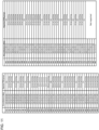
- Fig. 7 is a diagram illustrating an example of a correspondence between the PA architecture and the group of Fig. 6A .
- a configuration in a case where each PA corresponding to four transmission ports can take three output powers (23 dBm, 20 dBm, and 17 dBm) in consideration of all the UE capabilities 1 to 3 is illustrated.
- the leftmost column shows an index for convenience for associating the PA architecture and the TPMI group.
- there are 81 ( 3 4 ) possible index values.
- Indexes #1 to #64 correspond to the PA architectures of UE capability 3 including one to three output powers of 23 dBm.
- Indexes #65 to #75 correspond to the PA architectures of UE capability 2 that does not include the output power of 23 dBm.
- Index #76 corresponds to the PA architecture of UE capability 1 including only the output power of 23 dBm.
- Indexes #77 to #81 correspond to the PA architectures with which full power transmission cannot be performed with the non coherent precoder or partial coherent precoder.
- Mode 2 in which TPMI group reporting is required corresponds to UE capability 2 or 3. Therefore, it may be assumed that the UE does not need to report a TPMI group representing the PA architectures corresponding to indexes #77 to #81 in Fig. 7 .
- the column “PA architecture” in Fig. 7 shows the PA architecture.
- the column “Reported TPMI groups” in Fig. 7 indicates a group that can represent the PA architecture.
- the PA architecture of "GX w/switching" means that it is represented by switching of any port of the PA architecture of group GX (X is an integer).
- the PA architecture [17 23 17 17] of #16 can be implemented by switching ports #0 and #1 of the PA architecture ([23 17 17 17] of #15) of group G0.
- G0 to G4 can be used to report all required PA architectures.
- Figs. 8A and 8B are diagrams illustrating an example of TPMI groups that correspond to the PA architectures [20 17 17 17] and [17 17 17 17] and consider antenna port switching between arbitrary ports.
- Fig. 8A is different from Fig. 6A in that group G5 indicating that full power transmission can be performed only with the non-antenna selection precoder (full power transmission cannot be performed with the antenna selection precoder) is defined.
- Fig. 8B is different from Fig. 6B in that the value of the bit field of 5 indicates G5.
- Fig. 9 is a diagram illustrating an example of a correspondence between the PA architecture and the group of Fig. 8A .
- Fig. 9 is different from Fig. 7 in that indexes #77 to #81 are represented by G5 (or G5 w/switching).
- G0 to G5 can be used to report all required PA architectures.
- the full-coherent UE with the capability of G5 cannot perform UL full power transmission in a case where the antenna selection TPMI is specified from the network.
- the network configures an SRS resource set (e.g., an SRS resource set whose usage is the codebook) including more than two SRS resources for the UE of G5.
- the UE can use, for example, up to four PUSCH beams based on DCI instruction, so that flexible control can be performed.
- Figs. 10A and 10B are diagrams illustrating an example of TPMI groups that do not correspond to the PA architecture [23 17 17 17] and consider antenna port switching between arbitrary ports.
- Fig. 10A corresponds to a table in which G0 of Fig. 6A is deleted and G1 to G4 of Fig. 6A are defined as G0 to G3.
- the four groups in Fig. 10A can be represented by 2 bits as illustrated in Fig. 10B .
- the number of TPMI groups (or group sets) to be reported is reduced as compared to the group set as in Fig. 6A , thereby enabling efficient utilization of the capability information.
- the group set in Fig. 10A does not include the group (G0 of Fig. 6A ) indicating that full power transmission of only one port according to the non coherent TPMI is supported, but full power transmission using a plurality of ports is not supported. That is, in the group set in Fig. 10A , each group supports full power transmission using a plurality of ports.
- Fig. 11 is a diagram illustrating an example of a correspondence between the PA architecture and the group of Fig. 10A .
- Fig. 11 is different from Fig. 7 in that indexes #15 to #18 are not reported and G1 to G4 are changed to G0 to G3.
- the full-coherent UE that does not report the TPMI group capability information may perform full power transmission using a plurality of antenna ports (that is, full power transmission according to the TPMI corresponding to the partial coherent codebook or full-coherent codebook).
- the full-coherent UE can perform determination, reporting, or the like of detailed PA architecture information by using the TPMI group capability information.
- the TPMI group for the full-coherent UE includes a TPMI group (G0 to G6 in Fig. 3A ) that has already been agreed to be introduced for the non coherent UE/partial coherent UE.
- TPMI groups and group sets described in the second embodiment may be used as the TPMI groups for the non coherent UE/partial coherent UE.
- Fig. 12 is a diagram illustrating an example of a TPMI group and a corresponding precoder enabling full power transmission according to the second embodiment.
- the TPMI groups in Fig. 12 are the same as the existing G0 to G6 in Fig. 3A .
- the UE may select at least one group from G0 to G6 in the table of Fig. 12 for the full-coherent UE and transmit TPMI group capability information indicating the selected group to the network.
- Fig. 13 is a diagram illustrating an example of TPMI group capability information indicating the TPMI group of Fig. 12 .
- a correspondence between a value of 4-bit TPMI group capability information ("Bit field mapped to index" of the drawing) that the partial coherent UE/full-coherent UE having four transmitting antenna ports (4Tx) can report and a corresponding group is shown.
- each of the values of the bit field of 0 to 6 corresponds to one group (G0 to G6). Reservation ("Reserved") is prescribed for the values of the bit field of 7 to 15. Note that the correspondence between the value of the bit field and the group is not limited thereto. The same applies to the following drawings related to the bit field.
- Fig. 14 is a diagram illustrating an example of a TPMI group and a corresponding precoder enabling full power transmission according to the second embodiment.
- the TPMI groups in Fig. 14 can include combinations of the existing G0 to G6 of Fig. 3A in addition to the existing G0 to G6 of Fig. 3A .
- G0 to G6 may correspond to the following PA architectures, respectively.
- the combinations of a plurality of groups may correspond to the following PA configurations, respectively.
- the UE may select at least one from the groups or group sets in the table of Fig. 14 for the full-coherent UE and transmit TPMI group capability information indicating the selected group or group set to the network.
- Fig. 15 is a diagram illustrating an example of TPMI group capability information indicating the TPMI group of Fig. 14 .
- Fig. 15 is different from Fig. 13 in that the values of the bit field of 7 to 12 correspond to ⁇ G0, G4 ⁇ , ⁇ G0, G5 ⁇ , ⁇ G0, G6 ⁇ , ⁇ G1, G5 ⁇ , ⁇ G1, G6 ⁇ , and ⁇ G2, G6 ⁇ , respectively.
- Fig. 16 is a diagram illustrating an example of a correspondence between the PA architecture and the group of Fig. 14 .
- This example is a table similar to that in Fig. 7 , and thus an overlapping description will be omitted.
- the PA architecture of "GX and GY” in the column “Reported TPMI groups” in Fig. 16 corresponds to ⁇ GX, GY ⁇ in Fig. 14 .
- the PA architecture of "GX and GY w/switching" means that it is represented by switching of any port of the PA architecture of a group set GX and GY (X and Y are integers).
- TPMI group in Fig. 14 does not correspond to the PA architecture [23 23 23 23] of index #76 as illustrated in Fig. 16 , but since this PA architecture is supported in mode 0 in the first place, it does not need to be reported in mode 2.
- the TPMI group in Fig. 14 is suitable in a case where antenna port switching can be performed between an arbitrary port pair (e.g., port 0 can be switched to any of ports 0, 1, 2, and 3). Meanwhile, even for the full-coherent UE, it is also conceivable to perform antenna port switching only between some port pairs (between a port pair included in the coherent port pairs of the partial coherent UE). For example, the UE can switch port 0 only with ports 0 and 2 that constitute the same coherent port pair of the partial coherent UE, and cannot switch port 0 with ports 1 and 3 that belong to a different coherent port pair of the partial coherent UE.
- Fig. 17 is a diagram illustrating an example of a TPMI group and a corresponding precoder enabling full power transmission according to the second embodiment.
- the TPMI groups of Fig. 17 are different from those of Fig. 12 in that G7 and G8 are added.
- G7 and G8 may correspond to the following PA architectures, respectively.
- the UE may select at least one from the groups or group sets in the table of Fig. 17 for the full-coherent UE and transmit TPMI group capability information indicating the selected group or group set to the network.
- Fig. 18 is a diagram illustrating an example of TPMI group capability information indicating the TPMI group of Fig. 17 .
- Fig. 18 is different from Fig. 13 in that the values of the bit field of 7 to 14 correspond to G7, G8, ⁇ G0, G4 ⁇ , ⁇ G0, G5 ⁇ , ⁇ G0, G6 ⁇ , ⁇ G1, G5 ⁇ , ⁇ G1, G6 ⁇ , and ⁇ G2, G6 ⁇ , respectively.
- Fig. 19 is a diagram illustrating an example of a correspondence between the PA architecture and the group of Fig. 17 . This example is a table similar to that in Fig. 7 , and thus an overlapping description will be omitted. In Fig. 19 , some PA architectures of Fig. 16 are replaced with G7 or G8.
- Still another group (e.g., G10 described in the first embodiment) may be introduced.
- Fig. 20 is a diagram illustrating an example of a TPMI group and a corresponding precoder enabling full power transmission according to a modification of the second embodiment.
- the TPMI groups of Fig. 20 correspond to the TPMI groups of Fig. 12 added with G10.
- Fig. 21 is a diagram illustrating an example of TPMI group capability information indicating the TPMI group of Fig. 20 .
- Fig. 21 is different from Fig. 13 in that the value of the bit field of 7 corresponds to G10.
- the full-coherent UE can perform determination, reporting, or the like of detailed PA architecture information by using the TPMI group capability information.
- the description is given on UL transmission using the antenna port assuming a PUSCH, but the full power transmission of at least one of other signals and channels can be controlled in addition to or in place of a PUSCH.
- the antenna port in the above-described respective embodiments can be at least one antenna port of a PUSCH (and demodulation reference signal (DMRS) and phase tracking reference signal (PTRS) for PUSCH), an uplink shared channel (physical uplink control channel (PUCCH)), a random access channel (physical random access channel (PRACH)), an SRS, or the like.
- DMRS demodulation reference signal
- PTRS phase tracking reference signal
- the full power transmission can be applied to at least one of these signals and channels.
- the UE may determine whether to use the TPMI group capability information of the first embodiment or the TPMI group capability information of the second embodiment depending on whether or not the UE has a capability to support antenna port switching between an arbitrary port pair (or whether or not to report information of the capability) (e.g., the first embodiment in a case of performing reporting).
- the UE may determine whether to use the TPMI group capability information of the first embodiment or the TPMI group capability information of the second embodiment depending on whether or not the UE has a capability to support antenna port switching between a port pair included in specific coherent port pairs (or whether or not to report information of the capability) (e.g., the second embodiment in a case of performing reporting).
- the numbers “23”, “20”, and “17” of the present disclosure are values with the output power of a power class 3 UE in mind, and the number is not limited thereto.
- "23” may be replaced with a first power value (e.g., the maximum output power of a UE of a certain power class), and "20” may be replaced with a second power value (e.g., maximum output power - 3 [dBm]).
- "17” may be replaced with a third power value (e.g., second power value - 3 [dBm]).
- radio communication system communication is performed using one or a combination of the radio communication methods according to the embodiments of the present disclosure.
- Fig. 22 is a diagram illustrating an example of a schematic configuration of the radio communication system according to one embodiment.
- a radio communication system 1 may be a system that implements communication using long term evolution (LTE), 5th generation mobile communication system New Radio (5G NR), and the like drafted as the specification by third generation partnership project (3GPP).
- LTE long term evolution
- 5G NR 5th generation mobile communication system New Radio
- 3GPP third generation partnership project
- the radio communication system 1 may support dual connectivity (multi-RAT dual connectivity (MR-DC)) between a plurality of radio access technologies (RATs).
- the MR-DC may include dual connectivity between LTE (evolved universal terrestrial radio access (E-UTRA)) and NR (E-UTRA-NR dual connectivity (EN-DC)), dual connectivity between NR and LTE (NR-E-UTRA dual connectivity (NE-DC)), and the like.
- LTE evolved universal terrestrial radio access
- EN-DC E-UTRA-NR dual connectivity
- NE-DC NR-E-UTRA dual connectivity
- an LTE (E-UTRA) base station eNB
- MN master node
- gNB NR base station
- SN secondary node
- an NR base station (gNB) is a MN
- an LTE (E-UTRA) base station (eNB) is an SN.
- the radio communication system 1 may support dual connectivity between a plurality of base stations in the same RAT (e.g., dual connectivity in which both a MN and an SN are NR base stations (gNBs) (NR-NR dual connectivity (NN-DC)).
- dual connectivity in which both a MN and an SN are NR base stations (gNBs)
- NR-NR dual connectivity (NN-DC) NR-NR dual connectivity
- the radio communication system 1 may include a base station 11 that forms a macro cell C1 with a relatively wide coverage and base stations 12 (12a to 12c) that are arranged within the macro cell C1 and form small cells C2 narrower than the macro cell C1.
- a user terminal 20 may be positioned in at least one cell.
- the arrangement, number, and the like of cells and the user terminals 20 are not limited to the aspects illustrated in the drawings.
- the base stations 11 and 12 will be collectively referred to as base stations 10 unless specified otherwise.
- the user terminal 20 may be connected to at least one of the plurality of base stations 10.
- the user terminal 20 may use at least one of carrier aggregation (CA) using a plurality of component carriers (CCs) or dual connectivity (DC).
- CA carrier aggregation
- CCs component carriers
- DC dual connectivity
- Each CC may be included in at least one of a first frequency range 1 (FR1) or a second frequency range 2 (FR2).
- the macro cell C1 may be included in FR1, and the small cell C2 may be included in FR2.
- FR1 may be a frequency range of 6 GHz or less (sub-6 GHz)
- FR2 may be a frequency range higher than 24 GHz (above-24 GHz). Note that the frequency ranges, definitions, and the like of FR1 and FR2 are not limited thereto, and, for example, FR1 may correspond to a frequency range higher than FR2.
- the user terminal 20 may perform communication in each CC using at least one of time division duplex (TDD) or frequency division duplex (FDD).
- TDD time division duplex
- FDD frequency division duplex
- the plurality of base stations 10 may be connected by wire (e.g., an optical fiber or an X2 interface in compliance with common public radio interface (CPRI)) or wirelessly (e.g., NR communication).
- wire e.g., an optical fiber or an X2 interface in compliance with common public radio interface (CPRI)
- NR communication e.g., NR communication
- IAB integrated access backhaul
- relay station relay
- the base station 10 may be connected to a core network 30 via another base station 10 or directly.
- the core network 30 may include, for example, at least one of evolved packet core (EPC), 5G core network (5GCN), or next generation core (NGC).
- EPC evolved packet core
- 5GCN 5G core network
- NGC next generation core
- the user terminal 20 may be a terminal supporting to at least one of communication methods such as LTE, LTE-A, and 5G.
- a radio access method based on orthogonal frequency division multiplexing may be used.
- OFDM orthogonal frequency division multiplexing
- DL downlink
- UL uplink
- CP-OFDM cyclic prefix OFDM
- DFT-s-OFDM discrete Fourier transform spread OFDM
- OFDMA orthogonal frequency division multiple access
- SC-FDMA single carrier frequency division multiple access
- the radio access method may be referred to as a waveform.
- another radio access method e.g., another single carrier transmission method or another multi-carrier transmission method
- the UL and DL radio access method may be used as the UL and DL radio access method.
- a downlink shared channel (physical downlink shared channel (PDSCH)) that is shared by respective user terminals 20, a broadcast channel (physical broadcast channel (PBCH)), a downlink control channel (physical downlink control channel (PDCCH)), or the like may be used.
- PDSCH physical downlink shared channel
- PBCH physical broadcast channel
- PDCCH physical downlink control channel
- an uplink shared channel (physical uplink shared channel (PUSCH)) that is shared by respective user terminals 20, an uplink control channel (physical uplink control channel (PUCCH)), a random access channel (physical random access channel (PRACH)), or the like may be used.
- PUSCH physical uplink shared channel
- PUCCH physical uplink control channel
- PRACH random access channel
- the PUSCH may transmit the user data, higher layer control information, and the like.
- the master information block (MIB) may be transmitted on the PBCH.
- Lower layer control information may be transmitted on the PDCCH.
- the lower layer control information may include, for example, downlink control information (DCI) including scheduling information of at least one of the PDSCH or the PUSCH.
- DCI downlink control information
- DCI that schedules the PDSCH may be referred to as DL assignment, DL DCI, or the like
- DCI that schedules the PUSCH may be referred to as UL grant, UL DCI, or the like.
- the PDSCH may be replaced with DL data
- the PUSCH may be replaced with UL data.
- a control resource set (CORESET) and a search space may be used to detect the PDCCH.
- the CORESET corresponds to a resource that searches for DCI.
- the search space corresponds to a search area and a search method for PDCCH candidates.
- One CORESET may be associated with one or more search spaces.
- the UE may monitor the CORESET associated with a certain search space based on search space configuration.
- One search space may correspond to a PDCCH candidate corresponding to one or more aggregation levels.
- One or more search spaces may be referred to as a search space set. Note that “search space” and “search space set”, “search space configuration” and “search space set configuration”, and “CORESET” and “CORESET configuration”, and the like in the present disclosure may be replaced with each other.
- Uplink control information including at least one of channel state information (CSI), delivery acknowledgement information (which may be referred to as, for example, hybrid automatic repeat request acknowledgement (HARQ-ACK), ACK/NACK, or the like), or scheduling request (SR) may be transmitted on the PUCCH.
- CSI channel state information
- HARQ-ACK hybrid automatic repeat request acknowledgement
- ACK/NACK ACK/NACK, or the like
- SR scheduling request
- a random access preamble for establishing connection with a cell may be transmitted on the PRACH.
- downlink, uplink, and the like may be expressed without “link”.
- various channels may be expressed without adding "physical" at the beginning thereof.
- a synchronization signal (SS), a downlink reference signal (DL-RS), and the like may be transmitted.
- a cell-specific reference signal (CRS), a channel state information reference signal (CSI-RS), a demodulation reference signal (DMRS), a positioning reference signal (PRS), a phase tracking reference signal (PTRS), and the like may be transmitted as DL-RSs.
- the synchronization signal may be, for example, at least one of a primary synchronization signal (PSS) or a secondary synchronization signal (SSS).
- a signal block including the SS (PSS or SSS) and the PBCH (and the DMRS for the PBCH) may be referred to as an SS/PBCH block, an SS block (SSB), or the like. Note that the SS, the SSB, or the like may also be referred to as a reference signal.
- a sounding reference signal (SRS), a demodulation reference signal (DMRS), and the like may be transmitted as an uplink reference signal (UL-RS).
- a DMRS may be referred to as a "user terminal-specific reference signal (UE-specific reference signal)".
- Fig. 23 is a diagram illustrating an example of a configuration of the base station according to one embodiment.
- the base station 10 includes a control section 110, a transmitting/receiving section 120, a transmission/reception antenna 130, and a transmission line interface 140. Note that one or more control sections 110, one or more transmitting/receiving sections 120, one or more transmission/reception antennas 130, and one or more transmission line interfaces 140 may be included.
- the control section 110 controls the entire base station 10.
- the control section 110 can be implemented by a controller, a control circuit, and the like that are described based on common recognition in the technical field related to the present disclosure.
- the control section 110 may control signal generation, scheduling (e.g., resource allocation or mapping), and the like.
- the control section 110 may control transmission/reception, measurement, and the like using the transmitting/receiving section 120, the transmission/reception antenna 130, and the transmission line interface 140.
- the control section 110 may generate data to be transmitted as a signal, control information, a sequence, and the like, and may forward the data, the control information, the sequence, and the like to the transmitting/receiving section 120.
- the control section 110 may perform call processing (such as configuration or release) of a communication channel, management of the state of the base station 10, management of a radio resource, and the like.
- the transmitting/receiving section 120 may include a baseband section 121, a radio frequency (RF) section 122, and a measurement section 123.
- the baseband section 121 may include a transmission processing section 1211 and a reception processing section 1212.
- the transmitting/receiving section 120 can be implemented by a transmitter/receiver, an RF circuit, a baseband circuit, a filter, a phase shifter, a measurement circuit, a transmission/reception circuit, and the like that are described based on common recognition in the technical field related to the present disclosure.
- the transmitting/receiving section 120 may be configured as an integrated transmitting/receiving section or may be implemented by a transmitting section and a receiving section.
- the transmitting section may be implemented by the transmission processing section 1211 and the RF section 122.
- the receiving section may be implemented by the reception processing section 1212, the RF section 122, and the measurement section 123.
- the transmission/reception antennas 130 can be implemented by antennas described based on common recognition in the technical field related to the present disclosure, for example, an array antenna.
- the transmitting/receiving section 120 may transmit the above-described downlink channel, synchronization signal, downlink reference signal, and the like.
- the transmitting/receiving section 120 may receive the above-described uplink channel, uplink reference signal, and the like.
- the transmitting/receiving section 120 may form at least one of a Tx beam or a reception beam by using digital beam forming (e.g., precoding), analog beam forming (e.g., phase rotation), and the like.
- digital beam forming e.g., precoding
- analog beam forming e.g., phase rotation
- the transmitting/receiving section 120 may perform packet data convergence protocol (PDCP) layer processing, radio link control (RLC) layer processing (e.g., RLC retransmission control), medium access control (MAC) layer processing (e.g., HARQ retransmission control), and the like, for example, on data or control information acquired from the control section 110 to generate a bit string to be transmitted.
- PDCP packet data convergence protocol
- RLC radio link control
- MAC medium access control
- HARQ retransmission control HARQ retransmission control
- the transmitting/receiving section 120 may perform transmission processing such as channel coding (which may include error correction coding), modulation, mapping, filtering processing, discrete Fourier transform (DFT) processing (as necessary), inverse fast Fourier transform (IFFT) processing, precoding, or digital-analog conversion on the bit string to be transmitted and may output a baseband signal.
- transmission processing such as channel coding (which may include error correction coding), modulation, mapping, filtering processing, discrete Fourier transform (DFT) processing (as necessary), inverse fast Fourier transform (IFFT) processing, precoding, or digital-analog conversion on the bit string to be transmitted and may output a baseband signal.
- the transmitting/receiving section 120 may perform modulation to a radio frequency band, filtering processing, amplification, and the like on the baseband signal and may transmit a signal in a radio frequency band via a transmission/reception antenna 130.
- the transmitting/receiving section 120 may perform amplification, filtering processing, demodulation to a baseband signal, and the like on a signal in a radio frequency band received by a transmission/reception antenna 130.
- the transmitting/receiving section 120 may apply, on the acquired baseband signal, reception processing such as analog-digital conversion, fast Fourier transform (FFT) processing, inverse discrete Fourier transform (IDFT) processing (as necessary), filtering processing, demapping, demodulation, decoding (which may include error correction decoding), MAC layer processing, RLC layer processing, or PDCP layer processing to acquire user data and the like.
- reception processing such as analog-digital conversion, fast Fourier transform (FFT) processing, inverse discrete Fourier transform (IDFT) processing (as necessary), filtering processing, demapping, demodulation, decoding (which may include error correction decoding), MAC layer processing, RLC layer processing, or PDCP layer processing to acquire user data and the like.
- reception processing such as analog-digital conversion, fast Fourier transform (FFT) processing, inverse discrete Fourier transform (IDFT) processing (as necessary), filtering processing, demapping, demodulation, decoding (which may include error correction decoding), MAC
- the transmitting/receiving section 120 may perform measurement on the received signal.
- the measurement section 123 may perform radio resource management (RRM), channel state information (CSI) measurement, and the like based on the received signal.
- the measurement section 123 may measure received power (e.g., reference signal received power (RSRP)), received quality (e.g., reference signal received quality (RSRQ), a signal to interference plus noise ratio (SINR), a signal to noise ratio (SNR)), signal strength (e.g., received signal strength indicator (RSSI)), propagation path information (e.g., CSI), and the like.
- RSRP reference signal received power
- received quality e.g., reference signal received quality (RSRQ), a signal to interference plus noise ratio (SINR), a signal to noise ratio (SNR)
- signal strength e.g., received signal strength indicator (RSSI)
- propagation path information e.g., CSI
- CSI propagation path information
- the transmission line interface 140 may transmit/receive a signal (backhaul signaling) to and from an apparatus included in the core network 30, other base stations 10, and the like and may, for example, acquire or transmit user data (user plane data), control plane data, and the like for the user terminal 20.
- a signal backhaul signaling
- user data user plane data
- control plane data control plane data
- the transmitting section and the receiving section of the base station 10 in the present disclosure may be constituted by at least one of the transmitting/receiving section 120, the transmission/reception antenna 130, or the transmission line interface 140.
- the transmitting/receiving section 120 can receive, from the user terminal 20, at least one of capability information representing a mode for full power transmission to be supported (e.g., mode 1 or 2) or capability information representing a group of transmitted precoding matrix indicators (TPMIs) that support full power transmission (TPMI group capability information).
- capability information representing a mode for full power transmission to be supported
- TPMIs transmitted precoding matrix indicators
- the control section 110 may assume that the user terminal 20 generates the TPMI group capability information based on a second TPMI group set that is defined differently from a first TPMI group set for a terminal that supports the partial coherent codebook subset.
- the transmitting/receiving section 120 may receive the TPMI group capability information corresponding to the TPMI group that supports full power transmission, the TPMI group capability information being transmitted from the user terminal 20.
- Fig. 24 is a diagram illustrating an example of a configuration of the user terminal according to one embodiment.
- the user terminal 20 includes a control section 210, a transmitting/receiving section 220, and a transmission/reception antenna 230. Note that one or more of the control sections 210, one or more of the transmitting/receiving sections 220, and one or more of the transmission/reception antennas 230 may be included.
- the user terminal 20 includes other functional blocks that are necessary for radio communication as well. A part of processing of each section described below may be omitted.
- the control section 210 controls the entire user terminal 20.
- the control section 210 can be implemented by a controller, a control circuit, and the like that are described based on common recognition in the technical field related to the present disclosure.
- the control section 210 may control signal generation, mapping, and the like.
- the control section 210 may control transmission/reception, measurement, and the like using the transmitting/receiving section 220 and the transmission/reception antenna 230.
- the control section 210 may generate data to be transmitted as a signal, control information, a sequence, and the like, and may forward the data, the control information, the sequence, and the like to the transmitting/receiving section 220.
- the transmitting/receiving section 220 may include a baseband section 221, an RF section 222, and a measurement section 223.
- the baseband section 221 may include a transmission processing section 2211 and a reception processing section 2212.
- the transmitting/receiving section 220 can be implemented by a transmitter/receiver, an RF circuit, a baseband circuit, a filter, a phase shifter, a measurement circuit, a transmitting/receiving circuit, and the like that are described based on common recognition in the technical field related to the present disclosure.
- the transmitting/receiving section 220 may be configured as an integrated transmitting/receiving section, or may be implemented by a transmitting section and a receiving section.
- the transmitting section may be implemented by the transmission processing section 2211 and the RF section 222.
- the receiving section may be implemented by the reception processing section 2212, the RF section 222, and the measurement section 223.
- the transmission/reception antenna 230 can be implemented by an antenna that is described based on common recognition in the technical field related to the present disclosure, for example, an array antenna or the like.
- the transmitting/receiving section 220 may receive the above-described downlink channel, synchronization signal, downlink reference signal, and the like.
- the transmitting/receiving section 220 may transmit the above-described uplink channel, uplink reference signal, and the like.
- the transmitting/receiving section 220 may form at least one of a Tx beam or a reception beam by using digital beam forming (e.g., precoding), analog beam forming (e.g., phase rotation), and the like.
- digital beam forming e.g., precoding
- analog beam forming e.g., phase rotation
- the transmitting/receiving section 220 may perform PDCP layer processing, RLC layer processing (e.g., RLC retransmission control), MAC layer processing (e.g., HARQ retransmission control), and the like, for example, on data, control information, and the like acquired from the control section 210, to generate a bit string to be transmitted.
- RLC layer processing e.g., RLC retransmission control
- MAC layer processing e.g., HARQ retransmission control
- the transmitting/receiving section 220 may perform transmission processing such as channel coding (which may include error correction coding), modulation, mapping, filtering processing, DFT processing (if necessary), IFFT processing, precoding, or digital-analog conversion on the bit string to be transmitted, to output a baseband signal.
- transmission processing such as channel coding (which may include error correction coding), modulation, mapping, filtering processing, DFT processing (if necessary), IFFT processing, precoding, or digital-analog conversion on the bit string to be transmitted, to output a baseband signal.
- whether or not to apply DFT processing may be determined based on configuration of transform precoding.
- the transmitting/receiving section 220 may perform DFT processing as the transmission processing in order to transmit the channel using a DFT-s-OFDM waveform.
- DFT processing need not be performed as the transmission processing.
- the transmitting/receiving section 220 may perform modulation to a radio frequency range, filtering processing, amplification, and the like on the baseband signal, to transmit a signal in the radio frequency range via the transmission/reception antenna 230.
- the transmitting/receiving section 220 may perform amplification, filtering processing, demodulation to a baseband signal, and the like on the signal in the radio frequency range received by the transmission/reception antenna 230.
- the transmitting/receiving section 220 may apply reception processing such as analog-digital conversion, FFT processing, IDFT processing (if necessary), filtering processing, demapping, demodulation, decoding (which may include error correction decoding), MAC layer processing, RLC layer processing, or PDCP layer processing on the acquired baseband signal to acquire user data and the like.
- reception processing such as analog-digital conversion, FFT processing, IDFT processing (if necessary), filtering processing, demapping, demodulation, decoding (which may include error correction decoding), MAC layer processing, RLC layer processing, or PDCP layer processing on the acquired baseband signal to acquire user data and the like.
- the transmitting/receiving section 220 may perform measurement on the received signal.
- the measurement section 223 may perform RRM measurement, CSI measurement, and the like based on the received signal.
- the measurement section 223 may measure received power (e.g., RSRP), received quality (e.g., RSRQ, SINR, or SNR), signal strength (e.g., RSSI), propagation path information (e.g., CSI), and the like.
- the measurement result may be output to the control section 210.
- the transmitting section and the receiving section of the user terminal 20 in the present disclosure may include at least one of the transmitting/receiving section 220 or the transmission/reception antenna 230.
- the transmitting section may transmit mode 2 capability information indicating that mode 2 of full power transmission is supported.
- the mode 2 capability information may be replaced with modes-1-and-2 capability information indicating that mode 1 and mode 2 are supported, or may be replaced with mode 0 capability information indicating that mode 0 (UE capability 1) is supported.
- the control section 210 may generate the TPMI group capability information based on the second TPMI group set that is defined differently from the first TPMI group set for a terminal (or partial coherent UE) that supports the partial coherent codebook subset.
- the second TPMI group set may be a set of TPMI groups for a terminal (or full-coherent UE) that supports the full-coherent codebook subset.
- the control section 210 may determine a correspondence (e.g., the tables in Figs. 4 , 5 , 6A , 8A , 10A , 12 , 14 , and 17 ) between a bit (bit value) of the TPMI group capability information and the TPMI group (and/or group set).
- the control section 210 may specify the TPMI group corresponding to its own PA architecture with reference to at least one table.
- control section 210 does not have to directly store or use these tables.
- the control section 210 may perform the above processing by any method as long as the correspondences shown in these tables can be determined.
- a transmitting section may transmit the TPMI group capability information corresponding to the TPMI group that supports full power transmission.
- the control section 210 may assume that each group of the second TPMI group set includes a TPMI indicating the full-coherent codebook (e.g., the TPMI group set of Fig. 4 ). For example, the control section 210 may assume that each group of the second TPMI group set corresponds to the TPMI group of Fig. 4 .
- the control section 210 may assume that the second TPMI group set includes a TPMI group (e.g., G10) indicating that full power transmission can be performed only with the non-antenna selection precoder.
- a TPMI group e.g., G10
- the control section 210 may assume that the second TPMI group set does not include a TPMI group (e.g., G0 in Fig. 6A ) indicating that full power transmission using only one port is supported, but full power transmission using a plurality of ports is not supported.
- a TPMI group e.g., G0 in Fig. 6A
- the transmitting section may transmit an uplink shared channel (PUSCH) with full power by using a precoder based on a TPMI specified by DCI or the like.
- PUSCH uplink shared channel
- the transmitting section may transmit information indicating a set of TPMI groups as the TPMI group capability information.
- each functional block may be implemented by a single apparatus physically or logically aggregated, or may be implemented by directly or indirectly connecting two or more physically or logically separate apparatuses (in a wired manner, a radio manner, or the like, for example) and using these apparatuses.
- the functional blocks may be implemented by combining software with the above-described single apparatus or the above-described plurality of apparatuses.
- the function includes, but is not limited to, determining, judging, calculating, computing, processing, deriving, investigating, searching, ascertaining, receiving, transmitting, outputting, accessing, solving, selecting, choosing, establishing, comparing, assuming, expecting, regarding, broadcasting, notifying, communicating, forwarding, configuring, reconfiguring, allocating, mapping, assigning, and the like.
- a functional block (component) that has a transmission function may be referred to as a transmitting section (transmitting unit), a transmitter, and the like.
- the implementation method is not particularly limited.
- the base station, the user terminal, and the like in one embodiment of the present disclosure may function as a computer that performs the processing of the radio communication method of the present disclosure.
- Fig. 25 is a diagram illustrating an example of a hardware configuration of the base station and the user terminal according to one embodiment.
- the above-described base station 10 and user terminal 20 may be formed as a computer apparatus that includes a processor 1001, a memory 1002, a storage 1003, a communication apparatus 1004, an input apparatus 1005, an output apparatus 1006, a bus 1007, and the like.
- the terms such as an apparatus, a circuit, a device, a section, and a unit can be read as interchangeable with each other.
- the hardware configuration of the base station 10 and the user terminal 20 may be designed to include one or more of the apparatuses illustrated in the drawings, or may be designed not to include some apparatuses.
- processor 1001 may be implemented by one or more chips.
- Each function of the base station 10 and the user terminal 20 is implemented by given software (program) being read on hardware such as the processor 1001 and the memory 1002, by which the processor 1001 performs operations, controlling communication via the communication apparatus 1004, and controlling at least one of reading or writing of data at the memory 1002 and the storage 1003.
- software program
- the processor 1001 controls the entire computer by, for example, operating an operating system.
- the processor 1001 may be configured by a central processing unit (CPU) including an interface with peripheral equipment, a control apparatus, an operation apparatus, a register, and the like.
- CPU central processing unit
- control section 110 210
- transmitting/receiving section 120 220
- the like may be implemented by the processor 1001.
- the processor 1001 reads programs (program codes), software modules, data, etc. from at least one of the storage 1003 or the communication apparatus 1004 into the memory 1002, and performs various types of processing according to these.
- programs program codes
- software modules software modules
- data etc.
- the control section 110 (210) may be implemented by control programs that are stored in the memory 1002 and that operate on the processor 1001, and other functional blocks may be implemented likewise.
- the memory 1002 is a computer-readable recording medium, and may include, for example, at least one of a read only memory (ROM), an erasable programmable ROM (EPROM), an electrically EPROM (EEPROM), a random access memory (RAM), or other appropriate storage media.
- ROM read only memory
- EPROM erasable programmable ROM
- EEPROM electrically EPROM
- RAM random access memory
- the memory 1002 may be referred to as a register, a cache, a main memory (primary storage apparatus), and the like.
- the memory 1002 can store programs (program codes), software modules, etc. that are executable for implementing the radio communication method according to one embodiment of the present disclosure.
- the storage 1003 is a computer-readable recording medium, and may include, for example, at least one of a flexible disk, a floppy (registered trademark) disk, a magneto-optical disk (e.g., a compact disc ROM (CD-ROM) and the like), a digital versatile disk, a Blu-ray (registered trademark) disk), a removable disk, a hard disk drive, a smart card, a flash memory device (e.g., a card, a stick, or a key drive), a magnetic stripe, a database, a server, or other appropriate storage media.
- the storage 1003 may be referred to as a "secondary storage apparatus".
- the communication apparatus 1004 is hardware (transmission/reception device) for performing inter-computer communication via at least one of a wired network or a wireless network, and is referred to as, for example, a network device, a network controller, a network card, a communication module, and the like.
- the communication apparatus 1004 may include a high frequency switch, a duplexer, a filter, a frequency synthesizer, and the like in order to implement, for example, at least one of frequency division duplex (FDD) or time division duplex (TDD).
- FDD frequency division duplex
- TDD time division duplex
- the transmitting/receiving section 120 (220), the transmission/reception antenna 130 (230), and the like described above may be implemented by the communication apparatus 1004.
- the transmitting/receiving section 120 (220) may be implemented by physically or logically separating the transmitting section 120a (220a) and the receiving section 120b (220b) from each other.
- the input apparatus 1005 is an input device for receiving input from the outside (for example, a keyboard, a mouse, a microphone, a switch, a button, a sensor, and the like).
- the output apparatus 1006 is an output device that performs output to the outside (e.g., a display, a speaker, a light emitting diode (LED) lamp, or the like). Note that the input apparatus 1005 and the output apparatus 1006 may be an integrated configuration (e.g., touch panel).
- the apparatuses such as the processor 1001 and the memory 1002 are connected by a bus 1007 for communicating information.
- the bus 1007 may be formed using a single bus, or may be formed using different buses for different connections between the apparatuses.
- the base station 10 and the user terminal 20 may include hardware such as a microprocessor, a digital signal processor (DSP), an application specific integrated circuit (ASIC), a programmable logic device (PLD), or a field programmable gate array (FPGA), and some or all of the functional blocks may be implemented by using the hardware.
- the processor 1001 may be implemented using at least one of these pieces of hardware.
- a channel, a symbol, and a signal may be read as interchangeable with each other.
- the signal may be a message.
- the reference signal can be abbreviated as an RS, and may be referred to as a pilot, a pilot signal, and the like, depending on which standard applies.
- a component carrier CC may be referred to as a cell, a frequency carrier, a carrier frequency, and the like.
- a radio frame may be comprised of one or more periods (frames) in the time domain.
- Each of the one or more periods (frames) included in the radio frame may be referred to as a subframe.
- the subframe may include one or more slots in the time domain.
- the subframe may be a fixed time duration (for example, 1 ms) that is not dependent on numerology.
- the numerology may be a communication parameter used for at least one of transmission or reception of a certain signal or channel.
- the numerology may indicate at least one of subcarrier spacing (SCS), a bandwidth, a symbol length, a cyclic prefix length, a transmission time interval (TTI), the number of symbols per TTI, a radio frame configuration, specific filtering processing performed by a transceiver in the frequency domain, or specific windowing processing performed by a transceiver in the time domain.
- SCS subcarrier spacing
- TTI transmission time interval
- the slot may include one or more symbols in the time domain (orthogonal frequency division multiplexing (OFDM) symbols, single carrier frequency division multiple access (SC-FDMA) symbols, and the like). Also, the slot may be a time unit based on numerology.
- OFDM orthogonal frequency division multiplexing
- SC-FDMA single carrier frequency division multiple access
- the slot may include a plurality of mini slots. Each mini slot may include one or more symbols in the time domain. Further, the mini slot may be referred to as a subslot. Each mini slot may include fewer symbols than the slot.
- a PDSCH (or PUSCH) transmitted in a time unit larger than the mini slot may be referred to as "PDSCH (PUSCH) mapping type A".
- a PDSCH (or a PUSCH) transmitted using a mini slot may be referred to as PDSCH (PUSCH) mapping type B.
- a radio frame, a subframe, a slot, a mini slot, and a symbol each represent a time unit in signal transmission.
- the radio frame, the subframe, the slot, the mini slot, and the symbol may be called by other applicable names, respectively.
- time units such as a frame, a subframe, a slot, a mini slot, and a symbol in the present disclosure may be replaced with each other.
- one subframe may be referred to as TTI
- a plurality of consecutive subframes may be referred to as TTI
- one slot or one mini slot may be referred to as TTI. That is, at least one of the subframe or the TTI may be a subframe (1 ms) in the existing LTE, may be a period shorter than 1 ms (e.g., one to thirteen symbols), or may be a period longer than 1 ms.
- a unit representing a TTI may be referred to as a slot, a mini slot, or the like instead of a subframe.
- a TTI refers to, for example, a minimum time unit of scheduling in radio communication.
- a base station performs scheduling to allocate radio resources (a frequency bandwidth, transmit power, and the like that can be used in each user terminal) to each user terminal in TTI units.
- radio resources a frequency bandwidth, transmit power, and the like that can be used in each user terminal.
- a TTI may be a transmission time unit of a channel-coded data packet (transport block), a code block, a codeword, etc. or may be a processing unit of scheduling, link adaptation, etc.
- a time interval e.g., the number of symbols
- a transport block, a code block, a codeword, or the like may be shorter than the TTI.
- one or more TTIs may be a minimum time unit of scheduling.
- the number of slots (the number of mini slots) constituting the minimum time unit of scheduling may be controlled.
- a TTI having a time duration of 1 ms may be referred to as a usual TTI (TTI in 3GPP Rel. 8 to 12), a normal TTI, a long TTI, a usual subframe, a normal subframe, a long subframe, a slot, or the like.
- a TTI that is shorter than the usual TTI may be referred to as a shortened TTI, a short TTI, a partial TTI (or fractional TTI), a shortened subframe, a short subframe, a mini slot, a subslot, a slot, or the like.
- a long TTI (such as a normal TTI or a subframe) may be replaced with a TTI having a duration exceeding 1 ms.
- a short TTI (such as a shortened TTI) may be replaced with a TTI having a TTI length less than the TTI length of a long TTI and more than or equal to 1 ms.
- a resource block is the unit of resource allocation in the time domain and the frequency domain, and may include one or more contiguous subcarriers in the frequency domain.
- the number of subcarriers included in the RB may be the same regardless of the numerology, and may be twelve, for example.
- the number of subcarriers included in an RB may be determined based on a numerology.
- An RB may include one or more symbols in the time domain, and may have a length of one slot, one mini slot, one subframe, or one TTI.
- One TTI, one subframe, etc. may each be comprised of one or more resource blocks.
- one or more RBs may be referred to as a physical resource block (PRB), a subcarrier group (SCG), a resource element group (REG), a PRB pair, an RB pair, and the like.
- PRB physical resource block
- SCG subcarrier group
- REG resource element group
- a resource block may include one or more resource elements (REs).
- REs resource elements
- one RE may be a radio resource domain of one subcarrier and one symbol.
- a bandwidth part (which may be referred to as a partial bandwidth or the like) may represent a subset of contiguous common resource blocks (RBs) for a certain numerology in a certain carrier.
- the common RB may be specified by the index of the RB based on a common reference point of the carrier.
- PRBs may be defined in a BWP and numbered within the BWP.
- the BWP may include a BWP for UL (UL BWP) and a BWP for DL (DL BWP).
- UL BWP UL BWP
- DL BWP DL BWP
- one or more BWPs may be configured within one carrier.
- At least one of the configured BWPs may be active, and the UE does not have to expect transmission/reception of a given signal/channel outside the active BWP.
- “cell”, “carrier”, etc. in the present disclosure may be replaced with "BWP”.
- radio frames, subframes, slots, mini slots, symbols, and the like described above are merely examples.
- configurations such as the number of subframes included in a radio frame, the number of slots per subframe or radio frame, the number of mini slots included in a slot, the number of symbols and RBs included in a slot or a mini slot, the number of subcarriers included in an RB, the number of symbols in a TTI, the symbol length, the length of cyclic prefix (CP), and the like can be variously changed.
- a radio resource may be specified by a given index.
- the information, signals, etc. described in the present disclosure may be represented using any of a variety of different technologies.
- data, an instruction, a command, information, a signal, a bit, a symbol, a chip, etc. which may be referred to throughout the above description, may be represented by a voltage, a current, an electromagnetic wave, a magnetic field or a magnetic particle, an optical field or an optical photon, or any combination of these.
- Information, signals, etc. can be output in at least one of a direction from a higher layer to a lower layer or a direction from a lower layer to a higher layer.
- Information, signals, etc. may be input and output via a plurality of network nodes.
- Input and output information, signals, etc. may be stored in a specific location (e.g., memory), or may be managed using a control table.
- the information, signals, and the like to be input and output can be overwritten, updated, or appended.
- the output information, signals, and the like may be deleted.
- Information, signals, etc. that have been input may be transmitted to another apparatus.
- Notification of information may be performed not only by using the aspects/embodiments described in the present disclosure but also using another method.
- the notification of information in the present disclosure may be performed by using physical layer signaling (e.g., downlink control information (DCI) or uplink control information (UCI)), higher layer signaling (e.g., radio resource control (RRC) signaling, broadcast information (master information block (MIB)), system information block (SIB), or the like), or medium access control (MAC) signaling), another signal, or a combination thereof.
- DCI downlink control information
- UCI uplink control information
- RRC radio resource control
- MIB master information block
- SIB system information block
- MAC medium access control
- the physical layer signaling may be referred to as Layer 1/Layer 2 (L1/L2) control information (L1/L2 control signal), L1 control information (L1 control signal), and the like.
- the RRC signaling may be referred to as an RRC message, and may be, for example, an RRC connection setup message, an RRC connection reconfiguration message and the like.
- notification of the MAC signaling may be performed using, for example, an MAC control element (CE).
- CE MAC control element
- reporting of given information does not necessarily have to be sent explicitly, and can be sent implicitly (for example, by not reporting this piece of information, by reporting another piece of information, and the like).
- Determination may be performed using a value represented by one bit (0 or 1), or may be performed using a Boolean represented by true or false, or may be performed by comparing numerical values (e.g., comparison with a given value).
- Software regardless of whether it is referred to as software, firmware, middleware, microcode, or a hardware description language, or referred to by another name, should be interpreted broadly to mean a command, a command set, a code, a code segment, a program code, a program, a subprogram, a software module, an application, a software application, a software package, a routine, a subroutine, an object, an executable file, an execution thread, a procedure, a function, etc.
- software, commands, information, and the like may be transmitted and received via communication media.
- a wired technology coaxial cable, optical fiber cable, twisted pair, digital subscriber line (DSL), or the like
- a wireless technology infrared rays, microwaves, and the like
- at least one of the wired technology or the wireless technology is included within the definition of a transmission medium.
- the terms “system” and “network” used in the present disclosure may be used interchangeably.
- the “network” may mean an apparatus (e.g., a base station) included in the network.
- precoding "precoder”, “weight (precoding weight)”, “quasi-co-location (QCL)", "transmission configuration indication state (TCI state)", “spatial relation”, “spatial domain filter”, “transmit power”, “phase rotation”, “antenna port”, “antenna port group”, “layer”, “number of layers”, “rank”, “resource”, “resource set”, “resource group”, “beam”, “beam width”, “beam angle”, “antenna”, “antenna element”, and “panel” can be used interchangeably.
- base station BS
- radio base station fixed station
- NodeB NodeB
- eNodeB eNodeB
- gNodeB gNodeB
- access point TP
- RP reception point
- TRP transmission/reception point
- the base station can accommodate one or more (e.g., three) cells.
- the entire coverage area of the base station can be partitioned into a plurality of smaller areas, and each smaller area can provide communication services through a base station subsystem (e.g., small base station for indoors (remote radio head (RRH))).
- RRH remote radio head
- the term "cell” or “sector” refers to a part or the whole of a coverage area of at least one of the base station or the base station subsystem that performs a communication service in this coverage.
- MS mobile station
- UE user equipment
- terminal terminal
- the mobile station may be referred to as a subscriber station, mobile unit, subscriber station, wireless unit, remote unit, mobile device, wireless device, wireless communication device, remote device, mobile subscriber station, access terminal, mobile terminal, wireless terminal, remote terminal, handset, user agent, mobile client, client, or some other suitable terms.
- At least one of the base station or mobile station may be called as a transmission apparatus, a reception apparatus, a wireless communication apparatus, and the like.
- at least one of the base station or the mobile station may be a device mounted on a moving object, a moving object itself, and the like.
- the moving object may be a transportation (e.g., a car, an airplane, or the like), an unmanned moving object (e.g., a drone, an autonomous car, or the like), or a (manned or unmanned) robot.
- at least one of the base station or the mobile station also includes an apparatus that does not necessarily move during a communication operation.
- at least one of the base station or the mobile station may be an Internet of Things (IoT) device such as a sensor.
- IoT Internet of Things
- the base station in the present disclosure may be read as interchangeable with the user terminal.
- each aspect/embodiment of the present disclosure may be applied to a configuration in which communication between the base station and the user terminal is replaced with communication among a plurality of user terminals (which may be referred to as, for example, device-to-device (D2D), vehicle-to-everything (V2X), and the like).
- the user terminal 20 may have the function of the above-described base station 10.
- terms such as "uplink” and “downlink” may be read as interchangeable with terms corresponding to communication between terminals (e.g., "side”). For example, an uplink channel, a downlink channel, etc. may be replaced with a side channel.
- a user terminal in the present disclosure may be replaced with a base station.
- the base station 10 may have the functions of the user terminal 20 described above.
- an operation performed by the base station may be performed by an upper node thereof in some cases.
- a network including one or more network nodes with base stations it is clear that various operations performed for communication with a terminal can be performed by a base station, one or more network nodes (examples of which include but are not limited to mobility management entity (MME) and serving-gateway (S-GW)) other than the base station, or a combination thereof.
- MME mobility management entity
- S-GW serving-gateway
- aspects/embodiments illustrated in the present disclosure may be used individually or in combinations, which may be switched depending on the mode of implementation. Further, the order of processing procedures, sequences, flowcharts, and the like of the aspects/embodiments described in the present disclosure may be re-ordered as long as there is no inconsistency. For example, the methods described in the present disclosure have presented various step elements using an exemplary order, and are not limited to the presented specific order.
- LTE long term evolution
- LTE-A LTE-advanced
- LTE-B LTE-beyond
- SUPER 3G IMT-Advanced
- 4th generation mobile communication system 4th generation mobile communication system
- 5G 5th generation mobile communication system
- 6G 6th generation mobile communication system
- xG xG
- xG xG
- FX new radio access technology
- GSM registered trademark
- CDMA 2000 CDMA 2000
- UMB ultra mobile broadband
- IEEE 802.11 Wi-Fi
- IEEE 802.16 WiMAX (registered trademark)
- IEEE 802.20 Ultra-WideBand (UWB), Bluetooth (registered trademark), or another appropriate radio communication method, a next generation system expanded based on these, and the
- references to the elements using designations such as “first” and “second” as used in the present disclosure do not generally limit the amount or sequence of these elements. These designations can be used in the present disclosure, as a convenient way of distinguishing between two or more elements. Thus, references to first and second elements do not mean that only the two elements can be employed, or that the first element must precede the second element in some form.
- determining may include a wide variety of operations. For example, “determining” may be regarded as “determining” judging, calculating, computing, processing, deriving, investigating, looking up (or searching or inquiring) (for example, looking up in a table, database, or another data structure), ascertaining, and the like.
- determining may be regarded as “determining” receiving (e.g., receiving information), transmitting (e.g., transmitting information), inputting, outputting, accessing (e.g., accessing data in memory), and the like.
- determining may be interpreted as “determining” resolving, selecting, choosing, establishing, comparing, and the like. That is, “determining” may be interpreted as “determining” some action.
- the "maximum transmit power" described in the present disclosure may mean a maximum value of transmit power, a nominal UE maximum transmit power, or a rated UE maximum transmit power.
- connection and “coupled” used in the present disclosure mean all direct or indirect connections or coupling between two or more elements, and may include the presence of one or more intermediate elements between two elements that are “connected” or “coupled” to each other.
- the coupling or connection between the elements may be physical, logical, or a combination of these. For example, “connection” may be replaced with "access”.
- the two elements when two elements are connected together, it is conceivable that the two elements are "connected” or “coupled” to each other by using one or more electrical wires, cables, printed electrical connections, and the like, and, as some non-limiting and non-inclusive examples, by using electromagnetic energy having wavelengths in the radio frequency domain, microwave region, or optical (both visible and invisible) region, or the like.
- the terms "A and B are different” may mean “A and B are different from each other”. Note that the phrase may mean that "A and B are different from C”.
- the terms such as “separate”, “coupled”, and the like may be interpreted similarly to "different”.
Landscapes
- Engineering & Computer Science (AREA)
- Computer Networks & Wireless Communication (AREA)
- Signal Processing (AREA)
- Physics & Mathematics (AREA)
- Mathematical Physics (AREA)
- Mobile Radio Communication Systems (AREA)
- Transmitters (AREA)
Applications Claiming Priority (1)
| Application Number | Priority Date | Filing Date | Title |
|---|---|---|---|
| PCT/JP2020/019304 WO2021229758A1 (ja) | 2020-05-14 | 2020-05-14 | 端末、無線通信方法及び基地局 |
Publications (2)
| Publication Number | Publication Date |
|---|---|
| EP4152787A1 true EP4152787A1 (de) | 2023-03-22 |
| EP4152787A4 EP4152787A4 (de) | 2024-01-17 |
Family
ID=78525558
Family Applications (1)
| Application Number | Title | Priority Date | Filing Date |
|---|---|---|---|
| EP20935423.2A Pending EP4152787A4 (de) | 2020-05-14 | 2020-05-14 | Endgerät, funkkommunikationsverfahren und basisstation |
Country Status (3)
| Country | Link |
|---|---|
| EP (1) | EP4152787A4 (de) |
| CN (1) | CN116114278A (de) |
| WO (1) | WO2021229758A1 (de) |
Cited By (1)
| Publication number | Priority date | Publication date | Assignee | Title |
|---|---|---|---|---|
| WO2024120647A1 (en) * | 2022-12-08 | 2024-06-13 | Telefonaktiebolaget Lm Ericsson (Publ) | Methods, devices, and computer program for uplink communication |
Families Citing this family (3)
| Publication number | Priority date | Publication date | Assignee | Title |
|---|---|---|---|---|
| CN117643135A (zh) * | 2022-06-28 | 2024-03-01 | 北京小米移动软件有限公司 | 一种上行mimo传输的天线全相干传输码字的确定方法及其装置 |
| WO2024096549A1 (ko) * | 2022-11-04 | 2024-05-10 | 엘지전자 주식회사 | 무선 통신 시스템에서 신호 송수신 방법 및 장치 |
| CN117155431B (zh) * | 2023-07-11 | 2024-02-09 | 深圳国人无线通信有限公司 | 基于mimo的pusch信道选择tpmi/ri的方法和装置 |
Family Cites Families (7)
| Publication number | Priority date | Publication date | Assignee | Title |
|---|---|---|---|---|
| EP3664308A4 (de) * | 2017-09-07 | 2020-06-17 | LG Electronics Inc. -1- | Verfahren zur übertragung eines uplink-signals auf basis eines codebuchs in einem drahtlosen kommunikationssystem und vorrichtung dafür |
| CN110036571B (zh) * | 2017-09-19 | 2021-08-20 | 联发科技股份有限公司 | 基于码本的上行链路传输方法 |
| WO2019095181A1 (en) * | 2017-11-16 | 2019-05-23 | Lenovo (Beijing) Limited | Determining a tpmi for a codebook set |
| US10952151B2 (en) * | 2018-04-19 | 2021-03-16 | Samsung Electronics Co., Ltd. | Uplink power control for advanced wireless communication systems |
| WO2020019136A1 (en) * | 2018-07-23 | 2020-01-30 | Qualcomm Incorporated | Configuration of sounding reference signal resource for multi-panel uplink transmission |
| US11191033B2 (en) * | 2018-08-03 | 2021-11-30 | Qualcomm Incorporated | Physical uplink shared channel power scaling to enhance power utilization at a user equipment |
| CN111010738B (zh) * | 2019-12-20 | 2021-12-24 | 北京紫光展锐通信技术有限公司 | 上行数据传输方法、用户设备及可读存储介质 |
-
2020
- 2020-05-14 CN CN202080104887.2A patent/CN116114278A/zh active Pending
- 2020-05-14 WO PCT/JP2020/019304 patent/WO2021229758A1/ja unknown
- 2020-05-14 EP EP20935423.2A patent/EP4152787A4/de active Pending
Cited By (1)
| Publication number | Priority date | Publication date | Assignee | Title |
|---|---|---|---|---|
| WO2024120647A1 (en) * | 2022-12-08 | 2024-06-13 | Telefonaktiebolaget Lm Ericsson (Publ) | Methods, devices, and computer program for uplink communication |
Also Published As
| Publication number | Publication date |
|---|---|
| WO2021229758A1 (ja) | 2021-11-18 |
| EP4152787A4 (de) | 2024-01-17 |
| CN116114278A (zh) | 2023-05-12 |
| JPWO2021229758A1 (de) | 2021-11-18 |
Similar Documents
| Publication | Publication Date | Title |
|---|---|---|
| EP3998793A1 (de) | Endgerät und drahtloskommunikationsverfahren | |
| WO2022149272A1 (ja) | 端末、無線通信方法及び基地局 | |
| EP4152787A1 (de) | Endgerät, funkkommunikationsverfahren und basisstation | |
| JP7244633B2 (ja) | 端末、無線通信方法、基地局及びシステム | |
| EP4040686A1 (de) | Endgerät und drahtloskommunikationsverfahren | |
| WO2022149274A1 (ja) | 端末、無線通信方法及び基地局 | |
| US20230397121A1 (en) | Terminal, radio communication method, and base station | |
| WO2021002018A1 (ja) | 端末及び無線通信方法 | |
| JP7351909B2 (ja) | 端末、無線通信方法、基地局及びシステム | |
| JP7344288B2 (ja) | 端末、無線通信方法、基地局及びシステム | |
| EP4075841A1 (de) | Endgerät und drahtloskommunikationsverfahren | |
| WO2021070392A1 (ja) | 端末及び無線通信方法 | |
| US20240014972A1 (en) | Terminal, radio communication method, and base station | |
| WO2020166086A1 (ja) | ユーザ端末及び無線通信方法 | |
| WO2021161541A1 (ja) | 端末、無線通信方法及び基地局 | |
| CN118077275A (zh) | 终端、无线通信方法以及基站 | |
| WO2020255419A1 (ja) | 端末及び無線通信方法 | |
| EP4106387A1 (de) | Benutzerendgerät, drahtloskommunikationsverfahren und basisstation | |
| WO2021156951A1 (ja) | 端末、無線通信方法及び基地局 | |
| EP4075883A1 (de) | Endgerät und drahtloskommunikationsverfahren | |
| EP4054086A1 (de) | Endgerät und drahtloskommunikationsverfahren | |
| WO2020194742A1 (ja) | ユーザ端末及び無線通信方法 | |
| WO2020194743A1 (ja) | ユーザ端末及び無線通信方法 | |
| EP4236416A1 (de) | Endgerät, drahtloskommunikationsverfahren und basisstation | |
| EP4109953A1 (de) | Benutzerendgerät, drahtloskommunikationsverfahren und basisstation |
Legal Events
| Date | Code | Title | Description |
|---|---|---|---|
| STAA | Information on the status of an ep patent application or granted ep patent |
Free format text: STATUS: THE INTERNATIONAL PUBLICATION HAS BEEN MADE |
|
| PUAI | Public reference made under article 153(3) epc to a published international application that has entered the european phase |
Free format text: ORIGINAL CODE: 0009012 |
|
| STAA | Information on the status of an ep patent application or granted ep patent |
Free format text: STATUS: REQUEST FOR EXAMINATION WAS MADE |
|
| 17P | Request for examination filed |
Effective date: 20221130 |
|
| AK | Designated contracting states |
Kind code of ref document: A1 Designated state(s): AL AT BE BG CH CY CZ DE DK EE ES FI FR GB GR HR HU IE IS IT LI LT LU LV MC MK MT NL NO PL PT RO RS SE SI SK SM TR |
|
| DAV | Request for validation of the european patent (deleted) | ||
| DAX | Request for extension of the european patent (deleted) | ||
| A4 | Supplementary search report drawn up and despatched |
Effective date: 20231220 |
|
| RIC1 | Information provided on ipc code assigned before grant |
Ipc: H04W 8/22 20090101AFI20231214BHEP |