EP4152596B1 - Verfahren zur steuerung der drehrichtung einer strömungsmaschine und verarbeitungseinheit mit konfiguration zur durchführung des verfahrens - Google Patents
Verfahren zur steuerung der drehrichtung einer strömungsmaschine und verarbeitungseinheit mit konfiguration zur durchführung des verfahrens Download PDFInfo
- Publication number
- EP4152596B1 EP4152596B1 EP22195549.5A EP22195549A EP4152596B1 EP 4152596 B1 EP4152596 B1 EP 4152596B1 EP 22195549 A EP22195549 A EP 22195549A EP 4152596 B1 EP4152596 B1 EP 4152596B1
- Authority
- EP
- European Patent Office
- Prior art keywords
- phase
- electric motor
- fluid machine
- rotation
- synchronous
- Prior art date
- Legal status (The legal status is an assumption and is not a legal conclusion. Google has not performed a legal analysis and makes no representation as to the accuracy of the status listed.)
- Active
Links
Images



Classifications
-
- H—ELECTRICITY
- H02—GENERATION; CONVERSION OR DISTRIBUTION OF ELECTRIC POWER
- H02P—CONTROL OR REGULATION OF ELECTRIC MOTORS, ELECTRIC GENERATORS OR DYNAMO-ELECTRIC CONVERTERS; CONTROLLING TRANSFORMERS, REACTORS OR CHOKE COILS
- H02P6/00—Arrangements for controlling synchronous motors or other dynamo-electric motors using electronic commutation dependent on the rotor position; Electronic commutators therefor
- H02P6/30—Arrangements for controlling the direction of rotation
-
- F—MECHANICAL ENGINEERING; LIGHTING; HEATING; WEAPONS; BLASTING
- F04—POSITIVE - DISPLACEMENT MACHINES FOR LIQUIDS; PUMPS FOR LIQUIDS OR ELASTIC FLUIDS
- F04D—NON-POSITIVE-DISPLACEMENT PUMPS
- F04D15/00—Control, e.g. regulation, of pumps, pumping installations or systems
-
- G—PHYSICS
- G01—MEASURING; TESTING
- G01P—MEASURING LINEAR OR ANGULAR SPEED, ACCELERATION, DECELERATION, OR SHOCK; INDICATING PRESENCE, ABSENCE, OR DIRECTION, OF MOVEMENT
- G01P13/00—Indicating or recording presence, absence, or direction, of movement
- G01P13/02—Indicating direction only, e.g. by weather vane
- G01P13/04—Indicating positive or negative direction of a linear movement or clockwise or anti-clockwise direction of a rotational movement
-
- H—ELECTRICITY
- H02—GENERATION; CONVERSION OR DISTRIBUTION OF ELECTRIC POWER
- H02H—EMERGENCY PROTECTIVE CIRCUIT ARRANGEMENTS
- H02H7/00—Emergency protective circuit arrangements specially adapted for specific types of electric machines or apparatus or for sectionalised protection of cable or line systems, and effecting automatic switching in the event of an undesired change from normal working conditions
- H02H7/08—Emergency protective circuit arrangements specially adapted for specific types of electric machines or apparatus or for sectionalised protection of cable or line systems, and effecting automatic switching in the event of an undesired change from normal working conditions for dynamo-electric motors
- H02H7/097—Emergency protective circuit arrangements specially adapted for specific types of electric machines or apparatus or for sectionalised protection of cable or line systems, and effecting automatic switching in the event of an undesired change from normal working conditions for dynamo-electric motors against wrong direction of rotation
-
- H—ELECTRICITY
- H02—GENERATION; CONVERSION OR DISTRIBUTION OF ELECTRIC POWER
- H02P—CONTROL OR REGULATION OF ELECTRIC MOTORS, ELECTRIC GENERATORS OR DYNAMO-ELECTRIC CONVERTERS; CONTROLLING TRANSFORMERS, REACTORS OR CHOKE COILS
- H02P6/00—Arrangements for controlling synchronous motors or other dynamo-electric motors using electronic commutation dependent on the rotor position; Electronic commutators therefor
- H02P6/20—Arrangements for starting
- H02P6/22—Arrangements for starting in a selected direction of rotation
-
- H—ELECTRICITY
- H02—GENERATION; CONVERSION OR DISTRIBUTION OF ELECTRIC POWER
- H02P—CONTROL OR REGULATION OF ELECTRIC MOTORS, ELECTRIC GENERATORS OR DYNAMO-ELECTRIC CONVERTERS; CONTROLLING TRANSFORMERS, REACTORS OR CHOKE COILS
- H02P6/00—Arrangements for controlling synchronous motors or other dynamo-electric motors using electronic commutation dependent on the rotor position; Electronic commutators therefor
- H02P6/24—Arrangements for stopping
-
- H—ELECTRICITY
- H02—GENERATION; CONVERSION OR DISTRIBUTION OF ELECTRIC POWER
- H02P—CONTROL OR REGULATION OF ELECTRIC MOTORS, ELECTRIC GENERATORS OR DYNAMO-ELECTRIC CONVERTERS; CONTROLLING TRANSFORMERS, REACTORS OR CHOKE COILS
- H02P6/00—Arrangements for controlling synchronous motors or other dynamo-electric motors using electronic commutation dependent on the rotor position; Electronic commutators therefor
- H02P6/26—Arrangements for controlling single phase motors
-
- F—MECHANICAL ENGINEERING; LIGHTING; HEATING; WEAPONS; BLASTING
- F05—INDEXING SCHEMES RELATING TO ENGINES OR PUMPS IN VARIOUS SUBCLASSES OF CLASSES F01-F04
- F05D—INDEXING SCHEME FOR ASPECTS RELATING TO NON-POSITIVE-DISPLACEMENT MACHINES OR ENGINES, GAS-TURBINES OR JET-PROPULSION PLANTS
- F05D2270/00—Control
- F05D2270/50—Control logic embodiments
- F05D2270/52—Control logic embodiments by electrical means, e.g. relays or switches
-
- F—MECHANICAL ENGINEERING; LIGHTING; HEATING; WEAPONS; BLASTING
- F05—INDEXING SCHEMES RELATING TO ENGINES OR PUMPS IN VARIOUS SUBCLASSES OF CLASSES F01-F04
- F05D—INDEXING SCHEME FOR ASPECTS RELATING TO NON-POSITIVE-DISPLACEMENT MACHINES OR ENGINES, GAS-TURBINES OR JET-PROPULSION PLANTS
- F05D2270/00—Control
- F05D2270/60—Control system actuates means
- F05D2270/62—Electrical actuators
Definitions
- the present invention relates to a method for controlling the direction of rotation of a fluid machine, as well as to a processing unit specifically arranged for implementing said method.
- the method is directed to controlling a washing pump or a discharge pump of a household appliance equipped with an oriented impeller, driven by means of a synchronous electric motor.
- the technical field of the invention relates to the field of fluid machines, particularly of pumps; specifically, the present invention finds its preferred application in the industrial field of large household appliances, for instance for controlling a washing or discharge pump in washing machines or dishwashing machines.
- the invention may be applied in all those fields where it is necessary to discriminate the direction of rotation of synchronous motors, for instance in the ventilation field.
- Synchronous electric motors in particular having permanent magnets, are known in the art, and are currently used in a plurality of applications, including the operation of components and pumps in the field of household appliances. In fact, these motors benefit from a high energy efficiency and excellent speed stability at steady state, in addition to relatively low production costs.
- synchronous electric motors especially of the single-phase type, have known drawbacks related to their start-up phase.
- these machines are bidirectional, namely they can start in an undifferentiated way in one or the other direction of rotation. If this does not entail a problem on electric pumps equipped with radial-blade impellers, which ensure the same performance in both directions of rotation, it is however necessary to introduce mechanical and/or electronic measures when using oriented-blade impellers, which have higher efficiency but must be started in the right direction.
- the direction control devices used in the synchronous electric pumps of large household appliances can use a position sensor, ensuring with absolute certainty the fulfillment of the required condition.
- Patent document US 2006/265890 A1 discloses a method for automatic determination of a rotation direction within electronically commutated motors. The method determines if the measured speed and applied torque are indicative of the desired direction of rotation for the blower.
- the technical problem underlying the present invention is to provide a method for controlling the direction of rotation of a fluid machine that ensures better results without entailing a significant increase in production costs.
- the step of applying a phase cutting corresponding to a reference power leads to the loss of synchronism of the electric motor when the impeller of the fluid machine rotates in the wrong direction, the method thus providing a step of restarting the electric motor.
- the present invention suggests a change of perspective with respect to the prior art systems, with which it can still be combined. In fact, if in the prior art an attempt is made to always ensure the motor starts in the desired direction, the present invention instead suggests a verification of the actual direction of rotation applied immediately following the starting.
- phase cutting already present in the motors of this type, is particularly advantageous since it allows performing the verification of the direction of rotation by forcing the cutting at a predefined value for a short time.
- the phase cutting corresponding to the reference power is in fact applied for a limited period of time, with the sole purpose of verifying the right rotation of the motor and causing, if not, the loss of synchronism.
- the phase cutting corresponding to the reference power may be a constant phase cutting which uses a reference phase angle.
- Said predefined phase angle may derive from theoretical interpolations or, preferably, from experimental results.
- phase current which is also possible, would however be less accurate given the range in the supply voltage and the tolerances of the components that make up the fluid machine, and would risk not to lead to reliable results.
- the motor used in the method according to the invention is a single-phase or two-phase synchronous electric motor controlled by TRIAC.
- the synchronous motor used is of the permanent magnet type.
- the phase angle is feedback-controlled in order to work in an optimum energy state.
- a method for the optimization of the phase cutting may provide for instance the feedback-control of said phase angle in order to cancel the phase displacement between the midpoint of a zero current plateau of a function of phase current supplied to the electric motor and the zero-crossing point of a counter electromotive force signal relating to the same phase.
- the fluid machine is the washing pump or the discharge pump of a household appliance such as a washing machine or a dishwashing machine.
- a household appliance such as a washing machine or a dishwashing machine.
- the invention may be similarly applied to fluid machines of another kind, as long as they use a synchronous motor and move an oriented-blade impeller; for instance, it can be used in the ventilation field.
- a processing unit for controlling a fluid machine said processing unit being arranged to control at least one power supply switch of a synchronous electric motor which operates said fluid machine by implementing the previously described control method.
- the unit controls a single switch in the case of a single-phase electric motor, but it controls two switches in the case of a two-phase electric motor.
- reference number 50 identifies a washing pump of a household appliance, in particular of a washing machine or a dishwashing machine (not represented in the appended figures).
- the pump 50 in a per se known manner, allows the supply and/or recirculation of the washing water within a washing chamber.
- the pump 50 used in the present invention has an oriented-blade impeller.
- the oriented-blade impellers per se known in the field, have a curvature of the blades with respect to the radius of the impeller itself.
- the pump 50 is operated by means of an electric motor 1 of the synchronous type; preferably, in the present invention, a single-phase permanent-magnet synchronous motor is used.
- An electronic device 20 which preferably takes the form of a control board, is associated with the electric motor 1 and is arranged to drive it by means of phase cutting.
- Said electronic device 20 comprises a static switch 21, in this specific case a TRIAC switch, arranged for the cutting of the current supplied by an electrical network 22 in alternating current and directed to the power supply windings of the electric motor 1.
- a static switch 21 in this specific case a TRIAC switch, arranged for the cutting of the current supplied by an electrical network 22 in alternating current and directed to the power supply windings of the electric motor 1.
- the TRIAC switch 21 is connected to an output 33 of a processing unit 30, which preferably takes the form of a microprocessor.
- the electronic device 20 may have a synchronization portion with the network 35 which sends a network synchronism signal 25 to the processing unit 30; the control of the output 33 may be synchronized with said network synchronism signal.
- the electronic device 20 has a power supply portion 36 of the processing unit, also arranged to provide said unit with a reference signal for the voltage.
- the processing unit 30 has a first inlet 31, which receives a mains voltage signal 23, and a second inlet 32, which instead receives a voltage signal across the switch 24.
- the processing unit 30 is able to carry out an indirect measurement of the counter-electromotive force generated by the synchronous motor 1, obtained as the difference between the mains voltage signal 23 and the voltage signal on the switch 24, at times when the current is zero.
- the processing unit 30 detects said zero current condition still evaluating the voltage signal across the switch 24, and in particular making sure that this signal sufficiently deviates from the zero value.
- the above electronic device 20 is able to start the electric motor 1 in a per se known manner, bringing it to a synchronism speed. This starting phase is identified with reference number 100 in the flow chart of figure 2 .
- the electronic device 20 is arranged to drive the electric motor 1 by means of phase cutting, namely by varying the phase angle ⁇ which determines the switch-on delay of the TRIAC switch with respect to the change in the sign of the mains current.
- phase angle ⁇ is feedback-controlled, in order to optimize the energy performance of the electric motor 1.
- the feedback-control occurs by identifying, as an ideal operating condition for the motor, the zero-crossing point of the electromotive force function at a midpoint of the zero current plateau imposed by the closing of the TRIAC switch 21.
- the extension of the zero current plateau and the relative position of its midpoint depend on the value of the phase angle ⁇ used for each half-period of current.
- the pursued condition corresponds to canceling the phase displacement between the power supply current of the windings and the counter-electromotive force generated by the synchronous motor 1, a condition which, as it is known, ensures the optimization of the energy efficiency of the synchronous motor itself (neglecting the losses in the iron).
- the processing unit 30 is able to evaluate how the behavior of the motor deviates with respect to the ideal operating condition, consequently feedback-correcting the phase angle ⁇ of the TRIAC switch 21.
- the driving of the pump 50 with phase cutting according to the above described modalities is forced, shortly after the starting, by imposing a constant cutting or a reference phase angle ⁇ 0 .
- Said phase angle ⁇ 0 is advantageously selected, based on the experimental results hereinafter discussed, so as to cause the loss of synchronism of the electric motor 1 should the impeller be rotating in the wrong direction of rotation; conversely, the power supplied remains sufficient to sustain the rotation of the impeller in the correct direction of rotation. Therefore, this phase, identified with reference number 300 in figure 2 , performs a test on the direction of rotation, and causes the motor to stop in the event of a wrong starting.
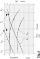
- the hydraulic performance of the pump 50 deteriorates significantly when the pump works in the wrong direction: indeed, the work point W wd corresponds to a significantly lower flow rate than that of the work point W rd with rotation in the right direction. Moreover, the power absorbed by the pump working in the wrong direction P wd is significantly higher than the pump working in the right direction P rd .
- the power absorbed by the pump with right rotation P rd is equal to about 42 W
- the power absorbed by the pump with wrong rotation P wd is equal to about 53 W
- the reference power Po selected stands at 47 W.
- the above reference power Po may be supplied by applying a constant and predefined cutting, in particular based on the above reference phase angle ⁇ 0 , which depending on the mains voltage that powers the household appliance (100 V in the examples herein considered) will correspond to the desired power.
- the value of the reference phase angle ⁇ 0 may be identified by means of experimental tests by using, for instance, the above driving algorithm with variable cutting and by verifying which cutting percentage is applied to the different mains voltages. Such experimental data d are shown in figure 5 , where they are graphed in comparison with some reference curves ref in the nominal and very bad cases with low and high temperature water.
- the previously described method and processing unit have the advantage of allowing an identification of the impeller starting in a non-optimal direction, using the components currently present on the washing/discharge pumps or other fluid machines, without additional production costs.
- the application of the method allows immediately avoiding starting in the wrong direction, already reduced in number thanks to the implementation of the mechanical and electronic measures known in the art.
- Another advantage derives from the fact that the method may be performed in a sensorless mode.
- phase current which is also possible, however would be less accurate given the range in the supply voltage and the tolerances of the components that make up the fluid machine and would risk not to lead to reliable results.
Landscapes
- Engineering & Computer Science (AREA)
- Power Engineering (AREA)
- Mechanical Engineering (AREA)
- General Engineering & Computer Science (AREA)
- Physics & Mathematics (AREA)
- General Physics & Mathematics (AREA)
- Control Of Non-Positive-Displacement Pumps (AREA)
- Electrical Discharge Machining, Electrochemical Machining, And Combined Machining (AREA)
- Structures Of Non-Positive Displacement Pumps (AREA)
Claims (9)
- Verfahren zur Steuerung der Drehrichtung einer Strömungsmaschine (50) mit einem Laufrad mit orientierten Schaufeln, das folgende Schritte aufweist:Starten (100) eines Synchronelektromotors (1), der die Strömungsmaschine (50) betreibt, bis der Synchronzustand erreicht ist;Ansteuern (200) des Synchronelektromotors (1) im stationären Zustand unter Anwendung eines Phasenschnitts;Anwenden (300) eines Phasenschnitts entsprechend einer Referenzleistung (P0), wobei die Referenzleistung (P0) zwischen einer ersten Leistung (Prd), die erforderlich ist, um die Rotation der Strömungsmaschine (50) in einer richtigen Richtung aufrechtzuerhalten, und einer zweiten Leistung (Pwd) liegt, die erforderlich ist, um die Rotation der Strömungsmaschine (50) in einer falschen Richtung aufrechtzuerhalten, die der richtigen Richtung entgegengesetzt ist;dadurch gekennzeichnet, dass der Schritt des Anwendens (300) eines Phasenschnitts entsprechend einer Referenzleistung (P0) zum Verlust der Synchronität des Elektromotors (1) führt, wenn sich das Laufrad der Strömungsmaschine (50) in der falschen Richtung dreht, wobei das Verfahren somit einen Schritt zum Neustarten des Elektromotors (1) bereitstellt.
- Verfahren nach Anspruch 1,
wobei der Phasenschnitt entsprechend der Referenzleistung (P0) ein konstanter Phasenschnitt ist, der einen Referenzphasenwinkel (α0) verwendet. - Verfahren nach Anspruch 2,
wobei der Referenzphasenwinkel (α0) aus experimentellen Ergebnissen abgeleitet wird. - Verfahren nach einem der vorhergehenden Ansprüche,
wobei der Phasenschnitt entsprechend der Referenzleistung (P0) für einen begrenzten Zeitraum angewendet wird. - Verfahren nach einem der vorhergehenden Ansprüche,
wobei der Elektromotor (1) ein einphasiger oder zweiphasiger Synchronelektromotor mit Permanentmagneten ist. - Verfahren nach einem der vorhergehenden Ansprüche,
wobei bei dem Schritt des Ansteuerns (200) des Synchronelektromotors (1) im stationären Zustand unter Anwendung eines Phasenschnitts der Phasenwinkel (α) zum Arbeiten in einem optimalen Energiezustand geregelt wird. - Verfahren nach Anspruch 6,
wobei bei dem Schritt des Ansteuerns (200) des Synchronelektromotors (1) im stationären Zustand unter Anwendung eines Phasenschnitts der Phasenwinkel (α) geregelt wird, um die Phasenverschiebung zwischen dem Mittelpunkt eines Nullstromplateaus einer Funktion des dem Elektromotor (1) zugeführten Phasenstroms und dem Nulldurchgangspunkt eines Signals der gegenelektromotorischen Kraft (fcem) aufzuheben, das sich auf die gleiche Phase bezieht. - Verfahren nach einem der vorhergehenden Ansprüche,
wobei die Strömungsmaschine (50) die Wasch- oder Ablaufpumpe eines Haushaltsgeräts wie einer Waschmaschine oder einer Geschirrspülmaschine oder ein Ventilator einer Lüftungsanlage ist. - Verarbeitungseinheit (30) zur Steuerung einer Strömungsmaschine (50), wobei die Verarbeitungseinheit (30) dazu ausgebildet ist, mindestens einen Stromversorgungsschalter (21) eines Synchronelektromotors (1) zu steuern, der die Strömungsmaschine (50) durch Ausführen des Steuerungsverfahrens nach einem der Ansprüche 1 bis 8 betreibt.
Applications Claiming Priority (1)
| Application Number | Priority Date | Filing Date | Title |
|---|---|---|---|
| IT102021000023915A IT202100023915A1 (it) | 2021-09-17 | 2021-09-17 | Metodo per il controllo del senso di rotazione di una macchina a fluido e unità di elaborazione configurata per realizzare detto metodo |
Publications (2)
| Publication Number | Publication Date |
|---|---|
| EP4152596A1 EP4152596A1 (de) | 2023-03-22 |
| EP4152596B1 true EP4152596B1 (de) | 2024-06-26 |
Family
ID=78771032
Family Applications (1)
| Application Number | Title | Priority Date | Filing Date |
|---|---|---|---|
| EP22195549.5A Active EP4152596B1 (de) | 2021-09-17 | 2022-09-14 | Verfahren zur steuerung der drehrichtung einer strömungsmaschine und verarbeitungseinheit mit konfiguration zur durchführung des verfahrens |
Country Status (7)
| Country | Link |
|---|---|
| US (1) | US12289075B2 (de) |
| EP (1) | EP4152596B1 (de) |
| CN (1) | CN115898898A (de) |
| CA (1) | CA3172818A1 (de) |
| ES (1) | ES2988347T3 (de) |
| IT (1) | IT202100023915A1 (de) |
| PL (1) | PL4152596T3 (de) |
Family Cites Families (5)
| Publication number | Priority date | Publication date | Assignee | Title |
|---|---|---|---|---|
| DE102005011731A1 (de) * | 2004-12-15 | 2006-07-20 | Aweco Appliance Systems Gmbh & Co. Kg | Einphasen-Synchronmotor |
| US7573217B2 (en) * | 2005-05-31 | 2009-08-11 | Regal-Beloit Corporation | Methods and systems for automatic rotation direction determination of electronically commutated motor |
| SI2410653T1 (sl) | 2010-07-23 | 2019-07-31 | Askoll Holding S.R.L. | Naprava za nadziranje sinhronega električnega motorja s permanentnim magnetnim rotorjem |
| EP2439840B1 (de) | 2010-10-11 | 2016-03-30 | Askoll Holding S.r.l. | Verfahren zur Regelung einer Haushaltsablaufpumpe und Prozessoreinheit zur Ausführung dieser Methode |
| CN109687780A (zh) * | 2017-08-25 | 2019-04-26 | 德昌电机(深圳)有限公司 | 电机及其驱动电路与驱动方法 |
-
2021
- 2021-09-17 IT IT102021000023915A patent/IT202100023915A1/it unknown
-
2022
- 2022-09-09 CA CA3172818A patent/CA3172818A1/en active Pending
- 2022-09-13 US US17/943,897 patent/US12289075B2/en active Active
- 2022-09-14 EP EP22195549.5A patent/EP4152596B1/de active Active
- 2022-09-14 ES ES22195549T patent/ES2988347T3/es active Active
- 2022-09-14 PL PL22195549.5T patent/PL4152596T3/pl unknown
- 2022-09-15 CN CN202211124791.XA patent/CN115898898A/zh active Pending
Also Published As
| Publication number | Publication date |
|---|---|
| US20230090353A1 (en) | 2023-03-23 |
| EP4152596A1 (de) | 2023-03-22 |
| US12289075B2 (en) | 2025-04-29 |
| PL4152596T3 (pl) | 2024-11-25 |
| CN115898898A (zh) | 2023-04-04 |
| ES2988347T3 (es) | 2024-11-20 |
| IT202100023915A1 (it) | 2023-03-17 |
| CA3172818A1 (en) | 2023-03-17 |
Similar Documents
| Publication | Publication Date | Title |
|---|---|---|
| US6642681B2 (en) | Starting control method of and control apparatus for synchronous motor, and air conditioner, refrigerator, washing machine and vacuum cleaner each provided with the control apparatus | |
| US9998059B2 (en) | Motor driving apparatus | |
| EP0621681B1 (de) | Startkontrollverfahren für Verdichter eines Kühlaggregats | |
| US7791309B2 (en) | Motor controller and method of controlling the motor | |
| KR100702913B1 (ko) | 브러시리스 dc 모터의 구동 방법 및 그 장치 | |
| CN101512893B (zh) | 用于起动并控制同步电动机的方法及相应的控制电路 | |
| JP4209900B2 (ja) | 回転磁界機械のための欠相検出 | |
| US20100148710A1 (en) | Apparatus and method for controlling a bldc motor | |
| KR100548843B1 (ko) | 직류 무브러시 모터의 제어 방법 | |
| JP2006149097A (ja) | モータ制御装置 | |
| JP4271860B2 (ja) | 特に水圧ポンプ運転用永久磁石同期モータの始動および定常状態供給方法 | |
| US12289075B2 (en) | Method for controlling the direction of rotation of a fluid machine and processing unit configured to perform said method | |
| JP2003111469A (ja) | モータの制御方法および制御装置 | |
| KR20060075262A (ko) | 비엘디씨 모터의 상전환 방법 | |
| JP3833918B2 (ja) | モータ制御装置 | |
| KR100859077B1 (ko) | 압축기 구동 모터의 기동제어 방법 | |
| EP1739822A1 (de) | Reglung für einen drei Phasen bürstenlosen Gleichstrommotor und entsprechendes Regelverfahren | |
| EP2134967B1 (de) | Elektroverdichter und klimaanlage damit | |
| JP2009017613A (ja) | 制御装置、駆動システム、および熱移動システム | |
| JP6673092B2 (ja) | 駆動装置 | |
| KR20210108253A (ko) | 모터 구동 장치 및 이를 구비하는 공기조화기 | |
| KR100807373B1 (ko) | 동기 모터의 제어방법 | |
| EP4625810A1 (de) | Motorantriebsvorrichtung, steuerungsverfahren dafür und durch einen motor angetriebene elektronische ausrüstung | |
| KR20250057439A (ko) | 모터 구동 장치, 그 제어 방법, 및 모터에 의하여 구동되는 전자 장치 | |
| KR102509725B1 (ko) | 모터 구동 장치 |
Legal Events
| Date | Code | Title | Description |
|---|---|---|---|
| PUAI | Public reference made under article 153(3) epc to a published international application that has entered the european phase |
Free format text: ORIGINAL CODE: 0009012 |
|
| STAA | Information on the status of an ep patent application or granted ep patent |
Free format text: STATUS: THE APPLICATION HAS BEEN PUBLISHED |
|
| AK | Designated contracting states |
Kind code of ref document: A1 Designated state(s): AL AT BE BG CH CY CZ DE DK EE ES FI FR GB GR HR HU IE IS IT LI LT LU LV MC MK MT NL NO PL PT RO RS SE SI SK SM TR |
|
| P01 | Opt-out of the competence of the unified patent court (upc) registered |
Effective date: 20230520 |
|
| STAA | Information on the status of an ep patent application or granted ep patent |
Free format text: STATUS: REQUEST FOR EXAMINATION WAS MADE |
|
| 17P | Request for examination filed |
Effective date: 20230906 |
|
| RBV | Designated contracting states (corrected) |
Designated state(s): AL AT BE BG CH CY CZ DE DK EE ES FI FR GB GR HR HU IE IS IT LI LT LU LV MC MK MT NL NO PL PT RO RS SE SI SK SM TR |
|
| GRAP | Despatch of communication of intention to grant a patent |
Free format text: ORIGINAL CODE: EPIDOSNIGR1 |
|
| STAA | Information on the status of an ep patent application or granted ep patent |
Free format text: STATUS: GRANT OF PATENT IS INTENDED |
|
| INTG | Intention to grant announced |
Effective date: 20240122 |
|
| GRAS | Grant fee paid |
Free format text: ORIGINAL CODE: EPIDOSNIGR3 |
|
| GRAA | (expected) grant |
Free format text: ORIGINAL CODE: 0009210 |
|
| STAA | Information on the status of an ep patent application or granted ep patent |
Free format text: STATUS: THE PATENT HAS BEEN GRANTED |
|
| AK | Designated contracting states |
Kind code of ref document: B1 Designated state(s): AL AT BE BG CH CY CZ DE DK EE ES FI FR GB GR HR HU IE IS IT LI LT LU LV MC MK MT NL NO PL PT RO RS SE SI SK SM TR |
|
| REG | Reference to a national code |
Ref country code: GB Ref legal event code: FG4D |
|
| REG | Reference to a national code |
Ref country code: CH Ref legal event code: EP |
|
| REG | Reference to a national code |
Ref country code: DE Ref legal event code: R096 Ref document number: 602022004138 Country of ref document: DE |
|
| PG25 | Lapsed in a contracting state [announced via postgrant information from national office to epo] |
Ref country code: BG Free format text: LAPSE BECAUSE OF FAILURE TO SUBMIT A TRANSLATION OF THE DESCRIPTION OR TO PAY THE FEE WITHIN THE PRESCRIBED TIME-LIMIT Effective date: 20240626 |
|
| PG25 | Lapsed in a contracting state [announced via postgrant information from national office to epo] |
Ref country code: FI Free format text: LAPSE BECAUSE OF FAILURE TO SUBMIT A TRANSLATION OF THE DESCRIPTION OR TO PAY THE FEE WITHIN THE PRESCRIBED TIME-LIMIT Effective date: 20240626 Ref country code: HR Free format text: LAPSE BECAUSE OF FAILURE TO SUBMIT A TRANSLATION OF THE DESCRIPTION OR TO PAY THE FEE WITHIN THE PRESCRIBED TIME-LIMIT Effective date: 20240626 |
|
| REG | Reference to a national code |
Ref country code: LT Ref legal event code: MG9D |
|
| PG25 | Lapsed in a contracting state [announced via postgrant information from national office to epo] |
Ref country code: GR Free format text: LAPSE BECAUSE OF FAILURE TO SUBMIT A TRANSLATION OF THE DESCRIPTION OR TO PAY THE FEE WITHIN THE PRESCRIBED TIME-LIMIT Effective date: 20240927 |
|
| PG25 | Lapsed in a contracting state [announced via postgrant information from national office to epo] |
Ref country code: LV Free format text: LAPSE BECAUSE OF FAILURE TO SUBMIT A TRANSLATION OF THE DESCRIPTION OR TO PAY THE FEE WITHIN THE PRESCRIBED TIME-LIMIT Effective date: 20240626 |
|
| REG | Reference to a national code |
Ref country code: NL Ref legal event code: MP Effective date: 20240626 |
|
| PG25 | Lapsed in a contracting state [announced via postgrant information from national office to epo] |
Ref country code: NO Free format text: LAPSE BECAUSE OF FAILURE TO SUBMIT A TRANSLATION OF THE DESCRIPTION OR TO PAY THE FEE WITHIN THE PRESCRIBED TIME-LIMIT Effective date: 20240926 Ref country code: LV Free format text: LAPSE BECAUSE OF FAILURE TO SUBMIT A TRANSLATION OF THE DESCRIPTION OR TO PAY THE FEE WITHIN THE PRESCRIBED TIME-LIMIT Effective date: 20240626 Ref country code: HR Free format text: LAPSE BECAUSE OF FAILURE TO SUBMIT A TRANSLATION OF THE DESCRIPTION OR TO PAY THE FEE WITHIN THE PRESCRIBED TIME-LIMIT Effective date: 20240626 Ref country code: GR Free format text: LAPSE BECAUSE OF FAILURE TO SUBMIT A TRANSLATION OF THE DESCRIPTION OR TO PAY THE FEE WITHIN THE PRESCRIBED TIME-LIMIT Effective date: 20240927 Ref country code: FI Free format text: LAPSE BECAUSE OF FAILURE TO SUBMIT A TRANSLATION OF THE DESCRIPTION OR TO PAY THE FEE WITHIN THE PRESCRIBED TIME-LIMIT Effective date: 20240626 Ref country code: BG Free format text: LAPSE BECAUSE OF FAILURE TO SUBMIT A TRANSLATION OF THE DESCRIPTION OR TO PAY THE FEE WITHIN THE PRESCRIBED TIME-LIMIT Effective date: 20240626 Ref country code: RS Free format text: LAPSE BECAUSE OF FAILURE TO SUBMIT A TRANSLATION OF THE DESCRIPTION OR TO PAY THE FEE WITHIN THE PRESCRIBED TIME-LIMIT Effective date: 20240926 |
|
| PG25 | Lapsed in a contracting state [announced via postgrant information from national office to epo] |
Ref country code: NL Free format text: LAPSE BECAUSE OF FAILURE TO SUBMIT A TRANSLATION OF THE DESCRIPTION OR TO PAY THE FEE WITHIN THE PRESCRIBED TIME-LIMIT Effective date: 20240626 |
|
| REG | Reference to a national code |
Ref country code: AT Ref legal event code: MK05 Ref document number: 1698538 Country of ref document: AT Kind code of ref document: T Effective date: 20240626 |
|
| REG | Reference to a national code |
Ref country code: ES Ref legal event code: FG2A Ref document number: 2988347 Country of ref document: ES Kind code of ref document: T3 Effective date: 20241120 |
|
| PG25 | Lapsed in a contracting state [announced via postgrant information from national office to epo] |
Ref country code: NL Free format text: LAPSE BECAUSE OF FAILURE TO SUBMIT A TRANSLATION OF THE DESCRIPTION OR TO PAY THE FEE WITHIN THE PRESCRIBED TIME-LIMIT Effective date: 20240626 |
|
| PG25 | Lapsed in a contracting state [announced via postgrant information from national office to epo] |
Ref country code: PT Free format text: LAPSE BECAUSE OF FAILURE TO SUBMIT A TRANSLATION OF THE DESCRIPTION OR TO PAY THE FEE WITHIN THE PRESCRIBED TIME-LIMIT Effective date: 20241028 |
|
| PG25 | Lapsed in a contracting state [announced via postgrant information from national office to epo] |
Ref country code: PT Free format text: LAPSE BECAUSE OF FAILURE TO SUBMIT A TRANSLATION OF THE DESCRIPTION OR TO PAY THE FEE WITHIN THE PRESCRIBED TIME-LIMIT Effective date: 20241028 |
|
| PG25 | Lapsed in a contracting state [announced via postgrant information from national office to epo] |
Ref country code: EE Free format text: LAPSE BECAUSE OF FAILURE TO SUBMIT A TRANSLATION OF THE DESCRIPTION OR TO PAY THE FEE WITHIN THE PRESCRIBED TIME-LIMIT Effective date: 20240626 |
|
| PG25 | Lapsed in a contracting state [announced via postgrant information from national office to epo] |
Ref country code: AT Free format text: LAPSE BECAUSE OF FAILURE TO SUBMIT A TRANSLATION OF THE DESCRIPTION OR TO PAY THE FEE WITHIN THE PRESCRIBED TIME-LIMIT Effective date: 20240626 Ref country code: IS Free format text: LAPSE BECAUSE OF FAILURE TO SUBMIT A TRANSLATION OF THE DESCRIPTION OR TO PAY THE FEE WITHIN THE PRESCRIBED TIME-LIMIT Effective date: 20241026 |
|
| PG25 | Lapsed in a contracting state [announced via postgrant information from national office to epo] |
Ref country code: CZ Free format text: LAPSE BECAUSE OF FAILURE TO SUBMIT A TRANSLATION OF THE DESCRIPTION OR TO PAY THE FEE WITHIN THE PRESCRIBED TIME-LIMIT Effective date: 20240626 |
|
| PG25 | Lapsed in a contracting state [announced via postgrant information from national office to epo] |
Ref country code: RO Free format text: LAPSE BECAUSE OF FAILURE TO SUBMIT A TRANSLATION OF THE DESCRIPTION OR TO PAY THE FEE WITHIN THE PRESCRIBED TIME-LIMIT Effective date: 20240626 Ref country code: SK Free format text: LAPSE BECAUSE OF FAILURE TO SUBMIT A TRANSLATION OF THE DESCRIPTION OR TO PAY THE FEE WITHIN THE PRESCRIBED TIME-LIMIT Effective date: 20240626 |
|
| PG25 | Lapsed in a contracting state [announced via postgrant information from national office to epo] |
Ref country code: SM Free format text: LAPSE BECAUSE OF FAILURE TO SUBMIT A TRANSLATION OF THE DESCRIPTION OR TO PAY THE FEE WITHIN THE PRESCRIBED TIME-LIMIT Effective date: 20240626 |
|
| PG25 | Lapsed in a contracting state [announced via postgrant information from national office to epo] |
Ref country code: SM Free format text: LAPSE BECAUSE OF FAILURE TO SUBMIT A TRANSLATION OF THE DESCRIPTION OR TO PAY THE FEE WITHIN THE PRESCRIBED TIME-LIMIT Effective date: 20240626 Ref country code: SK Free format text: LAPSE BECAUSE OF FAILURE TO SUBMIT A TRANSLATION OF THE DESCRIPTION OR TO PAY THE FEE WITHIN THE PRESCRIBED TIME-LIMIT Effective date: 20240626 Ref country code: RO Free format text: LAPSE BECAUSE OF FAILURE TO SUBMIT A TRANSLATION OF THE DESCRIPTION OR TO PAY THE FEE WITHIN THE PRESCRIBED TIME-LIMIT Effective date: 20240626 Ref country code: IS Free format text: LAPSE BECAUSE OF FAILURE TO SUBMIT A TRANSLATION OF THE DESCRIPTION OR TO PAY THE FEE WITHIN THE PRESCRIBED TIME-LIMIT Effective date: 20241026 Ref country code: EE Free format text: LAPSE BECAUSE OF FAILURE TO SUBMIT A TRANSLATION OF THE DESCRIPTION OR TO PAY THE FEE WITHIN THE PRESCRIBED TIME-LIMIT Effective date: 20240626 Ref country code: CZ Free format text: LAPSE BECAUSE OF FAILURE TO SUBMIT A TRANSLATION OF THE DESCRIPTION OR TO PAY THE FEE WITHIN THE PRESCRIBED TIME-LIMIT Effective date: 20240626 Ref country code: AT Free format text: LAPSE BECAUSE OF FAILURE TO SUBMIT A TRANSLATION OF THE DESCRIPTION OR TO PAY THE FEE WITHIN THE PRESCRIBED TIME-LIMIT Effective date: 20240626 |
|
| REG | Reference to a national code |
Ref country code: DE Ref legal event code: R097 Ref document number: 602022004138 Country of ref document: DE |
|
| PG25 | Lapsed in a contracting state [announced via postgrant information from national office to epo] |
Ref country code: DK Free format text: LAPSE BECAUSE OF FAILURE TO SUBMIT A TRANSLATION OF THE DESCRIPTION OR TO PAY THE FEE WITHIN THE PRESCRIBED TIME-LIMIT Effective date: 20240626 |
|
| PG25 | Lapsed in a contracting state [announced via postgrant information from national office to epo] |
Ref country code: MC Free format text: LAPSE BECAUSE OF FAILURE TO SUBMIT A TRANSLATION OF THE DESCRIPTION OR TO PAY THE FEE WITHIN THE PRESCRIBED TIME-LIMIT Effective date: 20240626 |
|
| PLBE | No opposition filed within time limit |
Free format text: ORIGINAL CODE: 0009261 |
|
| STAA | Information on the status of an ep patent application or granted ep patent |
Free format text: STATUS: NO OPPOSITION FILED WITHIN TIME LIMIT |
|
| PG25 | Lapsed in a contracting state [announced via postgrant information from national office to epo] |
Ref country code: LU Free format text: LAPSE BECAUSE OF NON-PAYMENT OF DUE FEES Effective date: 20240914 |
|
| 26N | No opposition filed |
Effective date: 20250327 |
|
| REG | Reference to a national code |
Ref country code: BE Ref legal event code: MM Effective date: 20240930 |
|
| PG25 | Lapsed in a contracting state [announced via postgrant information from national office to epo] |
Ref country code: BE Free format text: LAPSE BECAUSE OF NON-PAYMENT OF DUE FEES Effective date: 20240930 |
|
| PG25 | Lapsed in a contracting state [announced via postgrant information from national office to epo] |
Ref country code: IE Free format text: LAPSE BECAUSE OF NON-PAYMENT OF DUE FEES Effective date: 20240914 |
|
| PG25 | Lapsed in a contracting state [announced via postgrant information from national office to epo] |
Ref country code: SE Free format text: LAPSE BECAUSE OF FAILURE TO SUBMIT A TRANSLATION OF THE DESCRIPTION OR TO PAY THE FEE WITHIN THE PRESCRIBED TIME-LIMIT Effective date: 20240626 |
|
| PGFP | Annual fee paid to national office [announced via postgrant information from national office to epo] |
Ref country code: DE Payment date: 20250820 Year of fee payment: 4 |
|
| PGFP | Annual fee paid to national office [announced via postgrant information from national office to epo] |
Ref country code: TR Payment date: 20250825 Year of fee payment: 4 Ref country code: PL Payment date: 20250821 Year of fee payment: 4 |
|
| PGFP | Annual fee paid to national office [announced via postgrant information from national office to epo] |
Ref country code: FR Payment date: 20250820 Year of fee payment: 4 |
|
| PGFP | Annual fee paid to national office [announced via postgrant information from national office to epo] |
Ref country code: IT Payment date: 20250930 Year of fee payment: 4 |
|
| PG25 | Lapsed in a contracting state [announced via postgrant information from national office to epo] |
Ref country code: CY Free format text: LAPSE BECAUSE OF FAILURE TO SUBMIT A TRANSLATION OF THE DESCRIPTION OR TO PAY THE FEE WITHIN THE PRESCRIBED TIME-LIMIT; INVALID AB INITIO Effective date: 20220914 |
|
| PGFP | Annual fee paid to national office [announced via postgrant information from national office to epo] |
Ref country code: ES Payment date: 20251001 Year of fee payment: 4 |
|
| PG25 | Lapsed in a contracting state [announced via postgrant information from national office to epo] |
Ref country code: HU Free format text: LAPSE BECAUSE OF FAILURE TO SUBMIT A TRANSLATION OF THE DESCRIPTION OR TO PAY THE FEE WITHIN THE PRESCRIBED TIME-LIMIT; INVALID AB INITIO Effective date: 20220914 |
|
| REG | Reference to a national code |
Ref country code: CH Ref legal event code: H13 Free format text: ST27 STATUS EVENT CODE: U-0-0-H10-H13 (AS PROVIDED BY THE NATIONAL OFFICE) Effective date: 20260425 |