EP4152552B1 - Batterieladeverfahren und lade- und entladevorrichtung - Google Patents
Batterieladeverfahren und lade- und entladevorrichtung Download PDFInfo
- Publication number
- EP4152552B1 EP4152552B1 EP21819322.5A EP21819322A EP4152552B1 EP 4152552 B1 EP4152552 B1 EP 4152552B1 EP 21819322 A EP21819322 A EP 21819322A EP 4152552 B1 EP4152552 B1 EP 4152552B1
- Authority
- EP
- European Patent Office
- Prior art keywords
- battery
- charging
- converter
- current
- discharging
- Prior art date
- Legal status (The legal status is an assumption and is not a legal conclusion. Google has not performed a legal analysis and makes no representation as to the accuracy of the status listed.)
- Active
Links
Images


Classifications
-
- B—PERFORMING OPERATIONS; TRANSPORTING
- B60—VEHICLES IN GENERAL
- B60L—PROPULSION OF ELECTRICALLY-PROPELLED VEHICLES; SUPPLYING ELECTRIC POWER FOR AUXILIARY EQUIPMENT OF ELECTRICALLY-PROPELLED VEHICLES; ELECTRODYNAMIC BRAKE SYSTEMS FOR VEHICLES IN GENERAL; MAGNETIC SUSPENSION OR LEVITATION FOR VEHICLES; MONITORING OPERATING VARIABLES OF ELECTRICALLY-PROPELLED VEHICLES; ELECTRIC SAFETY DEVICES FOR ELECTRICALLY-PROPELLED VEHICLES
- B60L53/00—Methods of charging batteries, specially adapted for electric vehicles; Charging stations or on-board charging equipment therefor; Exchange of energy storage elements in electric vehicles
- B60L53/20—Methods of charging batteries, specially adapted for electric vehicles; Charging stations or on-board charging equipment therefor; Exchange of energy storage elements in electric vehicles characterised by converters located in the vehicle
- B60L53/24—Using the vehicle's propulsion converter for charging
-
- H02J7/865—
-
- H02J7/94—
-
- B—PERFORMING OPERATIONS; TRANSPORTING
- B60—VEHICLES IN GENERAL
- B60L—PROPULSION OF ELECTRICALLY-PROPELLED VEHICLES; SUPPLYING ELECTRIC POWER FOR AUXILIARY EQUIPMENT OF ELECTRICALLY-PROPELLED VEHICLES; ELECTRODYNAMIC BRAKE SYSTEMS FOR VEHICLES IN GENERAL; MAGNETIC SUSPENSION OR LEVITATION FOR VEHICLES; MONITORING OPERATING VARIABLES OF ELECTRICALLY-PROPELLED VEHICLES; ELECTRIC SAFETY DEVICES FOR ELECTRICALLY-PROPELLED VEHICLES
- B60L50/00—Electric propulsion with power supplied within the vehicle
- B60L50/50—Electric propulsion with power supplied within the vehicle using propulsion power supplied by batteries or fuel cells
- B60L50/60—Electric propulsion with power supplied within the vehicle using propulsion power supplied by batteries or fuel cells using power supplied by batteries
-
- B—PERFORMING OPERATIONS; TRANSPORTING
- B60—VEHICLES IN GENERAL
- B60L—PROPULSION OF ELECTRICALLY-PROPELLED VEHICLES; SUPPLYING ELECTRIC POWER FOR AUXILIARY EQUIPMENT OF ELECTRICALLY-PROPELLED VEHICLES; ELECTRODYNAMIC BRAKE SYSTEMS FOR VEHICLES IN GENERAL; MAGNETIC SUSPENSION OR LEVITATION FOR VEHICLES; MONITORING OPERATING VARIABLES OF ELECTRICALLY-PROPELLED VEHICLES; ELECTRIC SAFETY DEVICES FOR ELECTRICALLY-PROPELLED VEHICLES
- B60L53/00—Methods of charging batteries, specially adapted for electric vehicles; Charging stations or on-board charging equipment therefor; Exchange of energy storage elements in electric vehicles
- B60L53/30—Constructional details of charging stations
- B60L53/305—Communication interfaces
-
- B—PERFORMING OPERATIONS; TRANSPORTING
- B60—VEHICLES IN GENERAL
- B60L—PROPULSION OF ELECTRICALLY-PROPELLED VEHICLES; SUPPLYING ELECTRIC POWER FOR AUXILIARY EQUIPMENT OF ELECTRICALLY-PROPELLED VEHICLES; ELECTRODYNAMIC BRAKE SYSTEMS FOR VEHICLES IN GENERAL; MAGNETIC SUSPENSION OR LEVITATION FOR VEHICLES; MONITORING OPERATING VARIABLES OF ELECTRICALLY-PROPELLED VEHICLES; ELECTRIC SAFETY DEVICES FOR ELECTRICALLY-PROPELLED VEHICLES
- B60L53/00—Methods of charging batteries, specially adapted for electric vehicles; Charging stations or on-board charging equipment therefor; Exchange of energy storage elements in electric vehicles
- B60L53/50—Charging stations characterised by energy-storage or power-generation means
- B60L53/53—Batteries
-
- B—PERFORMING OPERATIONS; TRANSPORTING
- B60—VEHICLES IN GENERAL
- B60L—PROPULSION OF ELECTRICALLY-PROPELLED VEHICLES; SUPPLYING ELECTRIC POWER FOR AUXILIARY EQUIPMENT OF ELECTRICALLY-PROPELLED VEHICLES; ELECTRODYNAMIC BRAKE SYSTEMS FOR VEHICLES IN GENERAL; MAGNETIC SUSPENSION OR LEVITATION FOR VEHICLES; MONITORING OPERATING VARIABLES OF ELECTRICALLY-PROPELLED VEHICLES; ELECTRIC SAFETY DEVICES FOR ELECTRICALLY-PROPELLED VEHICLES
- B60L58/00—Methods or circuit arrangements for monitoring or controlling batteries or fuel cells, specially adapted for electric vehicles
- B60L58/10—Methods or circuit arrangements for monitoring or controlling batteries or fuel cells, specially adapted for electric vehicles for monitoring or controlling batteries
- B60L58/12—Methods or circuit arrangements for monitoring or controlling batteries or fuel cells, specially adapted for electric vehicles for monitoring or controlling batteries responding to state of charge [SoC]
- B60L58/13—Maintaining the SoC within a determined range
-
- B—PERFORMING OPERATIONS; TRANSPORTING
- B60—VEHICLES IN GENERAL
- B60L—PROPULSION OF ELECTRICALLY-PROPELLED VEHICLES; SUPPLYING ELECTRIC POWER FOR AUXILIARY EQUIPMENT OF ELECTRICALLY-PROPELLED VEHICLES; ELECTRODYNAMIC BRAKE SYSTEMS FOR VEHICLES IN GENERAL; MAGNETIC SUSPENSION OR LEVITATION FOR VEHICLES; MONITORING OPERATING VARIABLES OF ELECTRICALLY-PROPELLED VEHICLES; ELECTRIC SAFETY DEVICES FOR ELECTRICALLY-PROPELLED VEHICLES
- B60L58/00—Methods or circuit arrangements for monitoring or controlling batteries or fuel cells, specially adapted for electric vehicles
- B60L58/10—Methods or circuit arrangements for monitoring or controlling batteries or fuel cells, specially adapted for electric vehicles for monitoring or controlling batteries
- B60L58/12—Methods or circuit arrangements for monitoring or controlling batteries or fuel cells, specially adapted for electric vehicles for monitoring or controlling batteries responding to state of charge [SoC]
- B60L58/14—Preventing excessive discharging
-
- B—PERFORMING OPERATIONS; TRANSPORTING
- B60—VEHICLES IN GENERAL
- B60L—PROPULSION OF ELECTRICALLY-PROPELLED VEHICLES; SUPPLYING ELECTRIC POWER FOR AUXILIARY EQUIPMENT OF ELECTRICALLY-PROPELLED VEHICLES; ELECTRODYNAMIC BRAKE SYSTEMS FOR VEHICLES IN GENERAL; MAGNETIC SUSPENSION OR LEVITATION FOR VEHICLES; MONITORING OPERATING VARIABLES OF ELECTRICALLY-PROPELLED VEHICLES; ELECTRIC SAFETY DEVICES FOR ELECTRICALLY-PROPELLED VEHICLES
- B60L58/00—Methods or circuit arrangements for monitoring or controlling batteries or fuel cells, specially adapted for electric vehicles
- B60L58/10—Methods or circuit arrangements for monitoring or controlling batteries or fuel cells, specially adapted for electric vehicles for monitoring or controlling batteries
- B60L58/12—Methods or circuit arrangements for monitoring or controlling batteries or fuel cells, specially adapted for electric vehicles for monitoring or controlling batteries responding to state of charge [SoC]
- B60L58/15—Preventing overcharging
-
- B—PERFORMING OPERATIONS; TRANSPORTING
- B60—VEHICLES IN GENERAL
- B60L—PROPULSION OF ELECTRICALLY-PROPELLED VEHICLES; SUPPLYING ELECTRIC POWER FOR AUXILIARY EQUIPMENT OF ELECTRICALLY-PROPELLED VEHICLES; ELECTRODYNAMIC BRAKE SYSTEMS FOR VEHICLES IN GENERAL; MAGNETIC SUSPENSION OR LEVITATION FOR VEHICLES; MONITORING OPERATING VARIABLES OF ELECTRICALLY-PROPELLED VEHICLES; ELECTRIC SAFETY DEVICES FOR ELECTRICALLY-PROPELLED VEHICLES
- B60L58/00—Methods or circuit arrangements for monitoring or controlling batteries or fuel cells, specially adapted for electric vehicles
- B60L58/10—Methods or circuit arrangements for monitoring or controlling batteries or fuel cells, specially adapted for electric vehicles for monitoring or controlling batteries
- B60L58/18—Methods or circuit arrangements for monitoring or controlling batteries or fuel cells, specially adapted for electric vehicles for monitoring or controlling batteries of two or more battery modules
-
- H—ELECTRICITY
- H01—ELECTRIC ELEMENTS
- H01M—PROCESSES OR MEANS, e.g. BATTERIES, FOR THE DIRECT CONVERSION OF CHEMICAL ENERGY INTO ELECTRICAL ENERGY
- H01M10/00—Secondary cells; Manufacture thereof
- H01M10/42—Methods or arrangements for servicing or maintenance of secondary cells or secondary half-cells
- H01M10/425—Structural combination with electronic components, e.g. electronic circuits integrated to the outside of the casing
-
- H—ELECTRICITY
- H01—ELECTRIC ELEMENTS
- H01M—PROCESSES OR MEANS, e.g. BATTERIES, FOR THE DIRECT CONVERSION OF CHEMICAL ENERGY INTO ELECTRICAL ENERGY
- H01M10/00—Secondary cells; Manufacture thereof
- H01M10/42—Methods or arrangements for servicing or maintenance of secondary cells or secondary half-cells
- H01M10/44—Methods for charging or discharging
-
- H—ELECTRICITY
- H01—ELECTRIC ELEMENTS
- H01M—PROCESSES OR MEANS, e.g. BATTERIES, FOR THE DIRECT CONVERSION OF CHEMICAL ENERGY INTO ELECTRICAL ENERGY
- H01M10/00—Secondary cells; Manufacture thereof
- H01M10/42—Methods or arrangements for servicing or maintenance of secondary cells or secondary half-cells
- H01M10/48—Accumulators combined with arrangements for measuring, testing or indicating the condition of cells, e.g. the level or density of the electrolyte
-
- H—ELECTRICITY
- H02—GENERATION; CONVERSION OR DISTRIBUTION OF ELECTRIC POWER
- H02J—CIRCUIT ARRANGEMENTS OR SYSTEMS FOR SUPPLYING OR DISTRIBUTING ELECTRIC POWER; SYSTEMS FOR STORING ELECTRIC ENERGY
- H02J7/00—Circuit arrangements for charging or depolarising batteries or for supplying loads from batteries
- H02J7/02—Circuit arrangements for charging or depolarising batteries or for supplying loads from batteries for charging batteries from AC mains by converters
- H02J7/04—Regulation of charging current or voltage
-
- H—ELECTRICITY
- H02—GENERATION; CONVERSION OR DISTRIBUTION OF ELECTRIC POWER
- H02J—CIRCUIT ARRANGEMENTS OR SYSTEMS FOR SUPPLYING OR DISTRIBUTING ELECTRIC POWER; SYSTEMS FOR STORING ELECTRIC ENERGY
- H02J7/00—Circuit arrangements for charging or depolarising batteries or for supplying loads from batteries
- H02J7/34—Parallel operation in networks using both storage and other DC sources, e.g. providing buffering
- H02J7/342—The other DC source being a battery actively interacting with the first one, i.e. battery to battery charging
-
- H02J7/40—
-
- H02J7/82—
-
- H02J7/933—
-
- H02J7/947—
-
- H02J7/971—
-
- B—PERFORMING OPERATIONS; TRANSPORTING
- B60—VEHICLES IN GENERAL
- B60L—PROPULSION OF ELECTRICALLY-PROPELLED VEHICLES; SUPPLYING ELECTRIC POWER FOR AUXILIARY EQUIPMENT OF ELECTRICALLY-PROPELLED VEHICLES; ELECTRODYNAMIC BRAKE SYSTEMS FOR VEHICLES IN GENERAL; MAGNETIC SUSPENSION OR LEVITATION FOR VEHICLES; MONITORING OPERATING VARIABLES OF ELECTRICALLY-PROPELLED VEHICLES; ELECTRIC SAFETY DEVICES FOR ELECTRICALLY-PROPELLED VEHICLES
- B60L2210/00—Converter types
- B60L2210/10—DC to DC converters
-
- B—PERFORMING OPERATIONS; TRANSPORTING
- B60—VEHICLES IN GENERAL
- B60L—PROPULSION OF ELECTRICALLY-PROPELLED VEHICLES; SUPPLYING ELECTRIC POWER FOR AUXILIARY EQUIPMENT OF ELECTRICALLY-PROPELLED VEHICLES; ELECTRODYNAMIC BRAKE SYSTEMS FOR VEHICLES IN GENERAL; MAGNETIC SUSPENSION OR LEVITATION FOR VEHICLES; MONITORING OPERATING VARIABLES OF ELECTRICALLY-PROPELLED VEHICLES; ELECTRIC SAFETY DEVICES FOR ELECTRICALLY-PROPELLED VEHICLES
- B60L2210/00—Converter types
- B60L2210/30—AC to DC converters
-
- B—PERFORMING OPERATIONS; TRANSPORTING
- B60—VEHICLES IN GENERAL
- B60L—PROPULSION OF ELECTRICALLY-PROPELLED VEHICLES; SUPPLYING ELECTRIC POWER FOR AUXILIARY EQUIPMENT OF ELECTRICALLY-PROPELLED VEHICLES; ELECTRODYNAMIC BRAKE SYSTEMS FOR VEHICLES IN GENERAL; MAGNETIC SUSPENSION OR LEVITATION FOR VEHICLES; MONITORING OPERATING VARIABLES OF ELECTRICALLY-PROPELLED VEHICLES; ELECTRIC SAFETY DEVICES FOR ELECTRICALLY-PROPELLED VEHICLES
- B60L2240/00—Control parameters of input or output; Target parameters
- B60L2240/40—Drive Train control parameters
- B60L2240/54—Drive Train control parameters related to batteries
- B60L2240/545—Temperature
-
- B—PERFORMING OPERATIONS; TRANSPORTING
- B60—VEHICLES IN GENERAL
- B60L—PROPULSION OF ELECTRICALLY-PROPELLED VEHICLES; SUPPLYING ELECTRIC POWER FOR AUXILIARY EQUIPMENT OF ELECTRICALLY-PROPELLED VEHICLES; ELECTRODYNAMIC BRAKE SYSTEMS FOR VEHICLES IN GENERAL; MAGNETIC SUSPENSION OR LEVITATION FOR VEHICLES; MONITORING OPERATING VARIABLES OF ELECTRICALLY-PROPELLED VEHICLES; ELECTRIC SAFETY DEVICES FOR ELECTRICALLY-PROPELLED VEHICLES
- B60L2240/00—Control parameters of input or output; Target parameters
- B60L2240/40—Drive Train control parameters
- B60L2240/54—Drive Train control parameters related to batteries
- B60L2240/547—Voltage
-
- B—PERFORMING OPERATIONS; TRANSPORTING
- B60—VEHICLES IN GENERAL
- B60L—PROPULSION OF ELECTRICALLY-PROPELLED VEHICLES; SUPPLYING ELECTRIC POWER FOR AUXILIARY EQUIPMENT OF ELECTRICALLY-PROPELLED VEHICLES; ELECTRODYNAMIC BRAKE SYSTEMS FOR VEHICLES IN GENERAL; MAGNETIC SUSPENSION OR LEVITATION FOR VEHICLES; MONITORING OPERATING VARIABLES OF ELECTRICALLY-PROPELLED VEHICLES; ELECTRIC SAFETY DEVICES FOR ELECTRICALLY-PROPELLED VEHICLES
- B60L2240/00—Control parameters of input or output; Target parameters
- B60L2240/40—Drive Train control parameters
- B60L2240/54—Drive Train control parameters related to batteries
- B60L2240/549—Current
-
- B—PERFORMING OPERATIONS; TRANSPORTING
- B60—VEHICLES IN GENERAL
- B60Y—INDEXING SCHEME RELATING TO ASPECTS CROSS-CUTTING VEHICLE TECHNOLOGY
- B60Y2200/00—Type of vehicle
- B60Y2200/90—Vehicles comprising electric prime movers
- B60Y2200/91—Electric vehicles
-
- H—ELECTRICITY
- H01—ELECTRIC ELEMENTS
- H01M—PROCESSES OR MEANS, e.g. BATTERIES, FOR THE DIRECT CONVERSION OF CHEMICAL ENERGY INTO ELECTRICAL ENERGY
- H01M10/00—Secondary cells; Manufacture thereof
- H01M10/42—Methods or arrangements for servicing or maintenance of secondary cells or secondary half-cells
- H01M10/425—Structural combination with electronic components, e.g. electronic circuits integrated to the outside of the casing
- H01M2010/4271—Battery management systems including electronic circuits, e.g. control of current or voltage to keep battery in healthy state, cell balancing
-
- H—ELECTRICITY
- H01—ELECTRIC ELEMENTS
- H01M—PROCESSES OR MEANS, e.g. BATTERIES, FOR THE DIRECT CONVERSION OF CHEMICAL ENERGY INTO ELECTRICAL ENERGY
- H01M2220/00—Batteries for particular applications
- H01M2220/20—Batteries in motive systems, e.g. vehicle, ship, plane
-
- H—ELECTRICITY
- H02—GENERATION; CONVERSION OR DISTRIBUTION OF ELECTRIC POWER
- H02J—CIRCUIT ARRANGEMENTS OR SYSTEMS FOR SUPPLYING OR DISTRIBUTING ELECTRIC POWER; SYSTEMS FOR STORING ELECTRIC ENERGY
- H02J2207/00—Indexing scheme relating to details of circuit arrangements for charging or depolarising batteries or for supplying loads from batteries
- H02J2207/20—Charging or discharging characterised by the power electronics converter
-
- Y—GENERAL TAGGING OF NEW TECHNOLOGICAL DEVELOPMENTS; GENERAL TAGGING OF CROSS-SECTIONAL TECHNOLOGIES SPANNING OVER SEVERAL SECTIONS OF THE IPC; TECHNICAL SUBJECTS COVERED BY FORMER USPC CROSS-REFERENCE ART COLLECTIONS [XRACs] AND DIGESTS
- Y02—TECHNOLOGIES OR APPLICATIONS FOR MITIGATION OR ADAPTATION AGAINST CLIMATE CHANGE
- Y02E—REDUCTION OF GREENHOUSE GAS [GHG] EMISSIONS, RELATED TO ENERGY GENERATION, TRANSMISSION OR DISTRIBUTION
- Y02E60/00—Enabling technologies; Technologies with a potential or indirect contribution to GHG emissions mitigation
- Y02E60/10—Energy storage using batteries
-
- Y—GENERAL TAGGING OF NEW TECHNOLOGICAL DEVELOPMENTS; GENERAL TAGGING OF CROSS-SECTIONAL TECHNOLOGIES SPANNING OVER SEVERAL SECTIONS OF THE IPC; TECHNICAL SUBJECTS COVERED BY FORMER USPC CROSS-REFERENCE ART COLLECTIONS [XRACs] AND DIGESTS
- Y02—TECHNOLOGIES OR APPLICATIONS FOR MITIGATION OR ADAPTATION AGAINST CLIMATE CHANGE
- Y02T—CLIMATE CHANGE MITIGATION TECHNOLOGIES RELATED TO TRANSPORTATION
- Y02T10/00—Road transport of goods or passengers
- Y02T10/60—Other road transportation technologies with climate change mitigation effect
- Y02T10/70—Energy storage systems for electromobility, e.g. batteries
-
- Y—GENERAL TAGGING OF NEW TECHNOLOGICAL DEVELOPMENTS; GENERAL TAGGING OF CROSS-SECTIONAL TECHNOLOGIES SPANNING OVER SEVERAL SECTIONS OF THE IPC; TECHNICAL SUBJECTS COVERED BY FORMER USPC CROSS-REFERENCE ART COLLECTIONS [XRACs] AND DIGESTS
- Y02—TECHNOLOGIES OR APPLICATIONS FOR MITIGATION OR ADAPTATION AGAINST CLIMATE CHANGE
- Y02T—CLIMATE CHANGE MITIGATION TECHNOLOGIES RELATED TO TRANSPORTATION
- Y02T10/00—Road transport of goods or passengers
- Y02T10/60—Other road transportation technologies with climate change mitigation effect
- Y02T10/7072—Electromobility specific charging systems or methods for batteries, ultracapacitors, supercapacitors or double-layer capacitors
-
- Y—GENERAL TAGGING OF NEW TECHNOLOGICAL DEVELOPMENTS; GENERAL TAGGING OF CROSS-SECTIONAL TECHNOLOGIES SPANNING OVER SEVERAL SECTIONS OF THE IPC; TECHNICAL SUBJECTS COVERED BY FORMER USPC CROSS-REFERENCE ART COLLECTIONS [XRACs] AND DIGESTS
- Y02—TECHNOLOGIES OR APPLICATIONS FOR MITIGATION OR ADAPTATION AGAINST CLIMATE CHANGE
- Y02T—CLIMATE CHANGE MITIGATION TECHNOLOGIES RELATED TO TRANSPORTATION
- Y02T10/00—Road transport of goods or passengers
- Y02T10/60—Other road transportation technologies with climate change mitigation effect
- Y02T10/72—Electric energy management in electromobility
-
- Y—GENERAL TAGGING OF NEW TECHNOLOGICAL DEVELOPMENTS; GENERAL TAGGING OF CROSS-SECTIONAL TECHNOLOGIES SPANNING OVER SEVERAL SECTIONS OF THE IPC; TECHNICAL SUBJECTS COVERED BY FORMER USPC CROSS-REFERENCE ART COLLECTIONS [XRACs] AND DIGESTS
- Y02—TECHNOLOGIES OR APPLICATIONS FOR MITIGATION OR ADAPTATION AGAINST CLIMATE CHANGE
- Y02T—CLIMATE CHANGE MITIGATION TECHNOLOGIES RELATED TO TRANSPORTATION
- Y02T90/00—Enabling technologies or technologies with a potential or indirect contribution to GHG emissions mitigation
- Y02T90/10—Technologies relating to charging of electric vehicles
Definitions
- the present application relates to the field of batteries, in particular to a method for charging a battery and a charging and discharging device.
- US2010289457A1 discloses a method of providing power to an electronic device in an energy-efficient manner includes transitioning between power states corresponding to charging and discharging a battery.
- the state of charge of the battery is detected.
- an external power source such as an AC-to-DC adapter is disabled, and the battery to provides primary power to the electronic device.
- the AC-to-DC adapter is controlled to provide a high current output to charge the battery and provide primary power to the electronic device.
- the power states when cycled over time based on the state of the battery, provide for an energy-efficient method of powering the electronic device.
- US2017106764A1 discloses a battery system comprising plurality of batteries and a battery management system software controlling the operations of the battery system, function together with a vehicle charging system that charges electric vehicles using one or both of stored power provided by a battery system, and power provided by a utility power grid.
- the battery system uses the power grid to charge the batteries therein.
- WO2020124521A1 discloses a lithium battery charging method and a related device.
- the method comprises: charging a lithium battery to be charged according to a first preset current (210); acquiring a cathode voltage of the lithium battery (220); determining whether the cathode voltage satisfies a first preset condition according to the cathode voltage (230); if the cathode voltage satisfies the first preset condition, discharging the lithium battery according to a second preset current until the cathode voltage satisfies a second preset condition (240), wherein the second preset current is not greater than the first preset current; and repeating the steps.
- the method can improve the charging efficiency while ensuring the safety performance of the battery.
- power battery can be used as the main power source of power consumption apparatus (such as vehicle, ship or spacecraft, etc.), while energy storage battery can be used as the charging source of power consumption apparatus, both of which are self-evident.
- the power battery may be a battery in the power consumption apparatus and the energy storage battery may be a battery in a charging device.
- both the power battery and the energy storage battery may be collectively referred to as a battery for convenience of description.
- lithium batteries such as lithium-ion batteries or lithium-ion polymer batteries.
- the battery is charged by continuous charging, however, continuous charging of the battery will cause lithium plating and heat generation, which will not only degrade the performance of the battery, greatly shorten the cycle life, but also limit the fast charge capacity of the battery, and may cause disastrous consequences such as burning and explosion, resulting in serious safety problems.
- the present application provides a new method for charging battery and charging system.
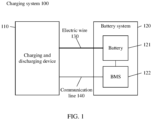
- FIG. 1 shows an architecture diagram of a charging system applicable to the embodiments of the present application.
- a charging system 100 may include a charging and discharging device 110 and a battery system 120.
- the battery system 200 may be a battery system in an electric vehicle (including a pure electric vehicle and a pluggable hybrid electric vehicle) or a battery system in other application scenarios.
- the battery 121 may be any type of battery, including but not limited to: a lithium ion battery, a lithium metal battery, a lithium sulfur battery, a lead acid battery, a nickel cadmium battery, a nickel hydrogen battery, a lithium air battery, and the like.
- the battery 121 in the embodiment of the present application may be a cell/battery cell, a battery module or a battery pack, each of which may be formed by a plurality of batteries in series and parallel.
- the specific type and scale of the battery 121 are not specifically limited.
- the battery system 120 is generally provided with a battery management system (BMS) 122 for monitoring the state of the battery 121.
- BMS battery management system
- the BMS 122 may be integrated with the battery 121 in the same device/apparatus, or the BMS 122 may be disposed outside the battery 121 as an independent device/apparatus.
- the charging and discharging device 110 is a device for supplementing electric energy for the battery 121 in the battery system 120 and/or controlling the discharge of the battery 121.
- the charging and discharging device 110 in the embodiments of the present application may be an ordinary charging pile, a super charging pile, a charging pile supporting a vehicle to grid (V2G) mode, or a charging and/or discharging device/ apparatus capable of charging and/or discharging a battery, etc.
- Embodiments of the present application are not limited to specific types and specific application scenarios of the charging and discharging device 110.
- the charging and discharging device 110 may be connected to the battery 121 through a electric wire 130 and to the BMS 122 through a communication line 140 for realizing information interaction between the charging and discharging device 110 and the BMS.
- the communication line 140 includes, but is not limited to, a control area network (CAN) communication bus or a daisy chain communication bus.
- CAN control area network
- the charging and discharging device 110 can communicate with the BMS 122 through a wireless network in addition to the communication line 140.
- Embodiments of the present application are not particularly limited to the type of wired communication or the type of wireless communication between the charging and discharging device and the BMS 122.
- FIG. 2 shows a schematic flow block diagram of a battery charging method 200 according to the embodiments of the present application.
- the method 200 of the embodiments of the present application may be applied to the charging and discharging device 110 and the battery system 120 shown above in FIG. 1 .
- the battery charging method 200 may include the following steps.
- Step 210 the Battery Management System BMS acquires a first charging current.
- Step 220 the BMS sends the first charging current to the charging and discharging device.
- Step 230 the charging and discharging device charges the battery based on the first charging current.
- Step 240 if a first cumulative charge amount of the battery is greater than or equal to a first cumulative charge amount threshold and a voltage of the battery cell of the battery does not exceed the full charge voltage of the battery cell, the BMS acquires a first discharging current.
- Step 250 the BMS sends a first discharging current to the charging and discharging device.
- Step 260 the charging and discharging device controls the battery to be discharged based on the first discharging current.
- a charging method which can be realized between a charging and discharging device and a BMS is provided, in the process of charging the battery, the charging and discharging device can realize charging and discharging the battery based on the first charging current and the first discharging current sent by BMS, thus avoiding the problems of heating, lithium ion accumulation and the like caused by continues charging of the battery.
- the charging and discharging device can realize charging and discharging the battery based on the first charging current and the first discharging current sent by BMS, thus avoiding the problems of heating, lithium ion accumulation and the like caused by continues charging of the battery.
- heating will cause the temperature of the battery to rise, crystals produced by lithium ion accumulation may puncture the battery, causing electrolyte leakage and short circuit of the battery.
- the temperature rise and short circuit of the battery may cause safety problems of the battery, such as burning or explosion of the battery.
- the charging and discharging device realizes the charging and discharging of the battery based on the first charging current and the first discharging current sent by the BMS, which can ensure the safety performance of the battery.
- the continuous aggregation of lithium ions will also cause lithium precipitation problems, which will affect the service life and charge capacity of the battery. Therefore, the technical solution of the embodiment of the present application can also ensure the service life and charge capacity of the battery.
- the BMS may first enter a charging mode to control the charging and discharging device to charge the battery. First, the BMS acquires the first charging current, and after the BMS sends the first charging current to the charging and discharging device, the charging and discharging device charges the battery based on the received first charging current.
- the BMS may acquire the first charging current from its own functional unit (e.g., the memory unit or the processing unit), or the BMS may also acquire the first charging current from other devices.
- the first charging current may be a preset current, the preset current may be a fixed value, or may vary over time in a preset manner.
- the first charging current may also be a current determined according to a state parameter of the battery, and the first charging current varies with a change in the state parameter of the battery.
- the charging and discharging device can be connected to a power source, which can be an AC power source and/or a DC power source. After receiving the information of the first charging current, the charging and discharging device charges the battery through the AC power source and/or the DC power source based on the first charging current.
- a power source which can be an AC power source and/or a DC power source.
- the BMS can acquire the first cumulative charge amount of the battery and judge whether the first cumulative charge amount is greater than or equal to the first cumulative charge amount threshold. If the first cumulative charge amount of the battery is greater than or equal to the first cumulative charge amount threshold and the voltage of the battery unit does not exceed the full charge voltage of the battery unit, the BMS acquires the first discharging current.
- the battery may include one or more battery cells, and the BMS may monitor whether the battery reaches a fully charged state by monitoring the voltages of one or more battery cells in the battery.
- the battery includes a plurality of battery cells, the voltages of the plurality of battery cells may be different, in which case it is possible to judge whether the battery reaches a full charge state by judging whether the maximum voltage of the battery cells exceeds the full charge voltage of the battery cells.
- other voltages of the battery cell in the battery may be used to judge whether the battery reaches the full charge state.
- the BMS acquires a first discharging current, that is, for the battery, the charging mode is switched to the discharging mode on the premise that the voltage of the battery cell of the battery does not exceed the full charge voltage of the battery cell, that is, the battery does not reach the full charge state.
- the above first cumulative charge amount may be a first cumulative charge capacity or may also be a first cumulative charge power amount.
- the first cumulative charge amount threshold is the first accumulative charge capacity threshold
- the first cumulative charge amount threshold is the first accumulative charge power amount threshold.
- the above first cumulative charge amount threshold may be a preset threshold, the preset threshold may be a fixed threshold, or may vary over time in a preset manner.
- the first cumulative charge amount threshold can also be determined according to the state parameter of the battery, that is, when the state parameter of the battery changes, the first cumulative charge amount threshold also changes accordingly.
- the first cumulative charge amount threshold can better adapt to the current state parameter of the battery, so as to better control the current charging process, improve the charging efficiency of the battery, and will not cause damage to the battery.
- the BMS acquires a first discharging current and sends the first discharging current to the charging and discharging device, which controls the battery to be discharged based on the received first discharging current.
- the BMS may acquire the first discharging current from its own functional unit (e.g., the memory unit or the processing unit), or the BMS may also acquire the first discharging current from other devices.
- the first discharging current may be a preset current, the preset current may be a fixed value, or may vary over time in a preset manner.
- the first discharging current may also be a current determined according to a state parameter of the battery, and the first discharging current varies with a change in the state parameter of the battery.
- electricity from the battery may be transferred to the energy storage device and/or the power grid during the discharging mode or discharging phase to facilitate the recycling of electrical energy.
- the energy storage device can be disposed in the charging and discharging device or outside the charging and discharging device, so as to enable the energy storage device to receive the discharging current of the battery.
- the embodiments of the present application do not limit the specific arrangement of the energy storage device.
- the battery power can be consumed in other ways, and the embodiments of the present application do not limit the specific mode of power consumption.
- the BMS can acquire the first cumulative discharge amount of the battery in the discharging process and judge whether the first cumulative discharge amount is greater than or equal to the first cumulative discharge amount threshold.
- the first cumulative discharge amount may be a first cumulative discharge capacity or may also be a first cumulative discharge amount.
- the first cumulative discharge amount threshold is the first cumulative discharge capacity threshold
- the first cumulative discharge amount threshold is the first cumulative discharge power amount threshold.
- the first cumulative discharge amount threshold may be a preset threshold, which may be a fixed threshold, or may vary over time in a preset manner.
- the first cumulative discharge amount threshold can also be determined according to the state parameter of the battery, that is, when the state parameter of the battery changes, the first cumulative discharge amount threshold also changes accordingly.
- the first cumulative discharge amount threshold can better adapt to the current state parameter of the battery, so as to better control the current discharging process, improve the discharging efficiency of the battery, and will not cause damage to the battery.
- the charging and discharging device controls the battery to stop discharging.
- the charging and discharging device can realize charging and discharging of the battery based on the first charging current and the first discharging current sent by the BMS, thereby avoiding the problems of heating and lithium ion accumulation caused by continuous charging of the battery, and then avoiding the safety problems of the battery caused by heating and lithium ion accumulation, such as burning or explosion of the battery, and ensuring the safety performance of the battery.
- the battery is charged to the first cumulative charge amount based on the first charging current and then the power amount of the battery is released to the first cumulative discharge amount based on the first discharging current, so that lithium ions accumulated in the negative electrode of the battery during the charging process can be released, and the lithium precipitation problem generated during continuous charging can be prevented, thereby improving the service life and charging ability of the battery.
- the battery can be recharged for the second time to continue charging the battery.
- the battery charging method 200 in the embodiments of the present application may further include the following steps.
- Step 270 if the first cumulative discharge amount of the battery is greater than or equal to the first cumulative discharge amount threshold, the BMS acquires a second charging current.
- Step 280 the BMS sends the second charging current to the charging and discharging device.
- Step 290 the charging and discharging device charges the battery based on the second charging current.
- steps 270 to 290 when the BMS judges that the first cumulative discharge amount of the battery is greater than or equal to the first cumulative discharge amount threshold, the BMS acquires the second charging current and sends the second charging current to a charging and discharging device, and the charging and discharging device continues to charge the battery based on the received second charging current, i.e., for the battery, the charging mode is re-entered from the discharging mode.
- steps 270 to 290 may be referred to above in relation to the description of steps 210 to 230 and will not be repeated here.
- the BMS acquires the first charging current and the first charging voltage, and sends the first charging current and the first charging voltage to the charging and discharging device for charging the battery based on the first charging current and the first charging voltage.
- the BMS acquires the first discharging current and the first discharging voltage and sends the first discharging current and the first discharging voltage to the charging and discharging device for discharging a battery based on the first discharging current and the first discharging voltage.
- the subsequent charging and discharging process can be similar to the above charging and discharging process and will not be described here.
- FIG. 3 is a schematic flow block diagram of another battery charging method 300 of the embodiments of the present application.
- the battery charging method 300 may further include the following steps in addition to steps 210 to 290 described above.
- Step 310 if the second cumulative charge amount of the battery is greater than or equal to the second cumulative charge amount threshold and the voltage of the battery cell of the battery does not exceed the full charge voltage of the battery cell, the BMS acquires the second discharging current.
- Step 320 the BMS sends the second discharging current to the charging and discharging device.
- Step 330 the charging and discharging device controls the battery to be discharged based on the second discharging current.
- the charging, discharging, re-charging and re-discharging of the battery are completed through the information interaction between the BMS and the charging and discharging device.
- the embodiments of the present application can further provide a charging and discharging method with multiple cycles, wherein the charging and discharging processes are cyclically carried out in turn, and the gradual charging of the battery is realized on the basis of ensuring the safety performance of the battery.
- step 310 when the charging and discharging device charges the battery based on the second charging current, the BMS can acquire the second cumulative charge amount of the battery and judge whether the second cumulative charge amount is greater than or equal to the second cumulative charge amount threshold.
- the second cumulative charge amount may be only the charge amount of the battery by the charging and discharging device based on the second charging current.
- the second cumulative charge amount threshold may be a charge amount threshold based on a single charging, or the second cumulative charge amount threshold may also be a charge amount threshold based on a total charge amount.
- the second cumulative charge amount may be a second cumulative charge capacity or may also be a second cumulative charge power amount.
- the second cumulative charge amount threshold is the second accumulative charge capacity threshold
- the second cumulative charge amount threshold is the second accumulative charge power amount threshold.
- the above second cumulative charge amount threshold may be a preset threshold, the preset threshold may be a fixed threshold, or may vary over time in a preset manner.
- the second cumulative charge amount threshold can also be determined according to the state parameter of the battery, that is, when the state parameter of the battery changes, the second cumulative charge amount threshold also changes accordingly.
- step 310 the BMS acquires the second discharging current when the second cumulative charge amount is greater than or equal to the second cumulative charge amount threshold, and the voltage of the battery cell of the battery does not exceed the full charge voltage of the battery cell. And in steps 320 to 330, the BMS sends the second discharging current to the charging and discharging device, and the charging and discharging device controls the battery to be discharged based on the received second discharging current.
- FIG. 4 shows a schematic waveform diagram of a charging current and a discharging current of a battery provided by an embodiment of the present application.
- the charging and discharging device charges the battery based on the first charging current, the charging continues until the first cumulative charge amount of the battery is greater than or equal to the first cumulative charge amount threshold, and the voltage of the battery cell of the battery does not exceed the full charge voltage of the battery cell.
- the charging and discharging device controls the battery to be discharged based on the first discharging current, the discharging continues until the first cumulative discharge amount of the battery is greater than or equal to the first cumulative discharge amount threshold, and
- a duration of the first discharging current may be less than a duration of the first charging current.
- the charging and discharging device continuously charges the battery based on the second charging current, the charging continues until the second cumulative charge amount of the battery is greater than or equal to the second cumulative charge amount threshold and the voltage of the battery cell of the battery does not exceed the full charge voltage of the battery cell.
- the charging and discharging device controls the battery to be discharged based on the second discharging current, the discharging continues until the second cumulative discharge amount of the battery is greater than or equal to the second cumulative discharge amount threshold, and optionally, a duration of the second charging current may be less than the duration of the first charging current. It can be understood that the charging and discharging process continues until the battery is fully charged.
- waveform diagrams of the first charging current, the second charging current, the first discharging current and the second discharging current are only schematically shown in FIG. 4
- the first charging current in the time period from t1 to t2 may be a constant current as shown in FIG. 4 , or may also be a time varying current
- the second charging current, the first discharging current and the second discharging current may be constant currents as shown in FIG. 4 , or may also be time varying currents.
- the magnitudes of the first charging current and the second charging current schematically shown in FIG. 4 are the same, and the magnitudes of the first discharging current and the second discharging current are also the same.
- the magnitudes of the first charging current and the second charging current may also be different, and the magnitudes of the first discharging current and the second discharging current may be different as well, which is not specifically limited by the embodiments of the present application.
- FIG. 5 is a schematic flow block diagram of another battery charging method 500 of the embodiments of the present application.
- the battery charging method 500 may further include the following steps in addition to steps 210 to 290 described above.
- Step 510 if the voltage of the battery cell of the battery exceeds the full charge voltage of the battery cell, the BMS sends a charge stop command to the charging and discharging device.
- Step 520 the charging and discharging device stops charging the battery.
- the BMS may monitor whether the battery reaches the fully charge state by monitoring the voltages of one or more battery cells in the battery.
- it may be determined whether the battery reaches a full charge state by determining whether the maximum voltage of the battery cell exceeds the full charge voltage of the battery cell.
- the maximum voltage of the battery cell exceeds the full charge voltage of the battery cell, it indicates that the battery reaches the full charge state, and the BMS sends the charge stop command to the charging and discharging device at this time, and the charge stop command is used to instruct the charging and discharging device to stop charging the battery, so that the charging and discharging device stops charging the battery.
- steps 510 and 520 may be performed during the charging phase of the battery.
- the BMS when the BMS enters the charging mode, and after the charging and discharging device receives the charging current sent by BMS, in the process of charging the battery, the BMS can acquire the voltage of the battery cell to judge whether the battery reaches the full charge state. Once the voltage of the battery cell exceeds the full charge voltage of the battery cell, the BMS sends the charge stop command to the charging and discharging device to make the charging and discharging device stop charging the battery.
- FIG. 5 only schematically shows that step 510 and step 520 are executed after step 290, i.e., executed in a process of the second charging, and it will be understood that step 510 and step 520 may also be executed during any one charging process of multiple charging and discharging processes.
- the charging and discharging device since the charging and discharging device is used for charging, discharging and recharging the battery, the safety problem caused by continuous charging to the battery can be prevented. Further, the charging current in the method can be a large current, so as to improve the charge amount of the battery in the single charging process and realize the purpose of rapid charging.
- the charging current is also limited, therefore, it is impossible to use continuous large current to realize rapid charging of the battery, according to the technical solution of the embodiment of the present application, the battery is charged by using a large current, and the battery is discharged after a large current charging, so as to release lithium ions accumulated in the negative electrode of the battery during the charging process, and then the battery can be recharged by using a large current to realize rapid charging of the battery.
- the first charging current and/or the second charging current may be large currents, and after the charging and discharging device charges the battery based on the second charging current, the charging current of the subsequent charging process may also be a large current.
- the charging rate of the first charging current and/or the second charging current ranges from 2C to 10C.
- the discharging current in the embodiments of the present application is a small current, aiming at releasing lithium ions gathered in the negative electrode of the battery through the discharge of the battery with the small current, without causing excessive loss of amount of charge which has entered the battery.
- the first discharging current and/or the second discharging current may be small currents, and after the charging and discharging device controls the battery to be discharged based on the second discharging current, the discharging current of the subsequent discharging process may also be a small current.
- the charging rate of the first discharging current and/or the second discharging current ranges from 0.1C to 1C.
- a ratio of the cumulative discharge amount threshold in the discharging process and the cumulative charge amount threshold in the charging process can be set so that the discharge amount is relatively small without causing excessive loss of the amount of charge which has entered the battery.
- a ratio of the first cumulative discharge amount threshold to the first cumulative charge amount threshold is less than or equal to 10%, and/or a ratio of the second cumulative discharge amount threshold to the second cumulative charge amount threshold is less than or equal to 10%.
- the ratio of the cumulative discharge amount threshold to the cumulative charge amount threshold in the subsequent charging and discharging process may also be less than or equal to 10%.
- the first charging current and the second charging current acquired by the BMS may be the same or different.
- the first charging current and/or the second charging current may be a preset current.
- the first charging current and/or the second charging current may also be currents determined according to the state parameter of the battery.
- the state parameter of the battery includes at least one of the following parameters: battery temperature, battery voltage, battery current, battery state of charge (SOC), battery state of health (SOH) and the like.
- first and second discharging currents acquired by the BMS may be the same or different.
- the first discharging current and/or the second discharging current may be a preset current, or the first discharging current and/or the second discharging current may also be a current determined according to the state parameter of the battery.
- At least one of the first charging current, the second charging current, the first discharging current and the second discharging current is a current determined according to the state parameter of the battery, it can better adapt to the current state parameter of the battery, improve the charging efficiency and/or discharging efficiency of the battery, and will not cause damage to the battery.
- the charging current and/or the discharging current in the subsequent charging and discharging process may also be preset currents, or may be currents determined according to the state parameters of the battery.
- FIG. 6 is a schematic flow block diagram of another battery charging method 600 of the embodiments of the present application.
- step 210 above may include: step 610: the BMS acquiring the state parameter of the battery and determines a first charging current according to the state parameter.
- Step 240 above may include: step 640: if a first cumulative charge amount of the battery is greater than or equal to a first cumulative charge amount threshold and a voltage of the battery cell of the battery does not exceed the full charge voltage of the battery cell, the BMS acquiring the state parameter of the battery and determines the first discharging current according to the state parameter.
- Step 270 above may include: step 670: if the first cumulative discharge amount of the battery is greater than or equal to the first cumulative discharge amount threshold, the BMS acquiring the state parameter of the battery and determines the second charging current according to the state parameter.
- the first charging current, the first discharging current and the second charging current are all currents determined according to the state parameters of the battery.
- BMS can obtain different state parameters of the battery in different time periods, and determine the current charging current and discharging current according to the state parameters.
- determining the charging current and the discharging current according to the state parameters of the battery can be realized in a plurality of ways.
- the mapping relationships between the state parameters of the battery and each of the charging current and the discharging current can be acquired, according to the mapping relationships, the specific charging current and discharging current are determined by the state parameters of the battery, wherein the mapping relationships can be obtained by fitting a large number of experimental data, which has high reliability and accuracy, and the mapping relationship can be a mapping table, a mapping diagram or a mapping formula, etc.
- a special neural network model can be trained according to a large number of experimental data, and the neural network model can output charging current and discharging current according to the input state parameters of the battery.
- the first cumulative charge amount threshold and the second cumulative charge amount threshold may be the same or different in the above method embodiments.
- the first cumulative discharge amount threshold and the second cumulative discharge amount threshold may be the same or different.
- At least one of the first cumulative charge amount threshold, the second cumulative charge amount threshold, the first cumulative discharge amount threshold and the second cumulative discharge amount threshold may be a preset threshold.
- at least one of the first cumulative charge amount threshold, the second cumulative charge amount threshold, the first cumulative discharge amount threshold and the second cumulative discharge amount threshold may be a threshold determined according to the state parameter of the battery.
- the cumulative discharge amount threshold and the cumulative charge amount threshold in the subsequent charging and discharging process may be preset thresholds or may be thresholds determined according to the state parameters of the battery.
- the first cumulative charge amount threshold, the second cumulative charge amount threshold, the first cumulative discharge amount threshold and the second cumulative discharge amount threshold is a threshold determined according to the state parameter of the battery, it can better adapt to the current state parameters of the battery, so as to better control the current charging process and/or discharging process, ensure the charge amount and discharge amount, and realize the efficient charging of the battery.
- At least one of the first charging current, the second charging current, the first discharging current and the second discharging current may be a current periodically or aperiodically acquired by the BMS.
- At least one of the first charging current, the second charging current, the first discharging current and the second discharging current may be a current periodically or aperiodically determined by the BMS based on a state parameter of the battery, The current varies with a change in a state parameter of the battery, in particular, the BMS may periodically acquire the state parameter of the battery to determine at least one of a first charging current, a second charging current, a first discharging current, and a second discharging current;
- the BMS acquires a state parameter of the battery in real time, and when the state parameter varies aperiodically, the BMS determines at least one of the first charging current, the second charging current, the first discharging current, and the second discharging current according to the a
- the BMS periodically or aperiodically sends at least one of the first charging current, the second charging current, the first discharging current, and the second discharging current to the charging and discharging device, such that the charging and discharging device charges the battery or controls the battery to be discharged based on the periodically or aperiodically sent current.
- the charging current and/or discharging current are sent periodically or aperiodically by the BMS, on the one hand, the charging current and/or discharging current can be periodically or aperiodically adjusted by the embodiment to improve the charging and discharging efficiency; on the other hand, the charging current and/or discharging current sent periodically or aperiodically can indicate that the state of the BMS and the battery is normal, and the charging and discharging device can continue to charge the battery or control the battery to be discharged.
- the charging and discharging device can stop charging the battery and/or stop controlling the battery to be discharged, so as to ensure the safety performance of the battery.
- FIG. 7 is a schematic flow block diagram of another battery charging method 700 of the embodiments of the present application.
- step 210 above may include:
- the BMS can periodically acquire the first charging current, the first discharging current, and the second charging current.
- the BMS can periodically send the first charging current, the first discharging current and the second charging current to the charging and discharging device.
- the communication between the BMS and the charging and discharging device is compatible with the existing communication protocol between the charger and the BMS, so that the communication between the BMS and the charging and discharging device is easy to realize and has a good application prospect.
- the BMS may also acquire at least one of a first charging voltage, a second charging voltage, a first discharging voltage, and a second discharging voltage, and sending at least one of the first charging voltage, the second charging voltage, the first discharging voltage and the second discharging voltage to the charging and discharging device, wherein the first charging current and the first charging voltage are carried in the first battery charging lab (BCL) message, and/or the first discharging current and the first discharging voltage are carried in the second BCL message, and/or the second charging current and the second charging voltage are carried in the third BCL message, and/or the second discharging current and the second discharging voltage are carried in the fourth BCL message.
- BCL battery charging lab
- the charging and discharging device charges the battery and controls the battery to be discharged based on the second charging current and the second discharging current
- the charging current, charging voltage, discharging current and discharging voltage in the subsequent charging and discharging process can also be carried in the BCL message and sent to the charging and discharging device through BMS.
- FIG. 8 is a schematic flow block diagram of another battery charging method 800 of the embodiments of the present application.
- the battery charging method 800 may include the following steps.
- Step 810 the BMS acquires a first charging current.
- Step 820 the BMS sends a first BCL message to the charging and discharging device, the first BCL message carrying a first charging current and a first charging voltage.
- Step 830 the charging and discharging device charges the battery based on the first charging current and the first charging voltage.
- Step 840 if a first cumulative charge amount of the battery is greater than or equal to a first cumulative charge amount threshold and a voltage of the battery cell of the battery does not exceed a full charge voltage of the battery cell, the BMS acquires a first discharging current and a first discharging voltage.
- Step 850 the BMS sends a second BCL message to the charging and discharging device, the second BCL message carrying the first discharging current and a first discharging voltage.
- Step 860 the charging and discharging device controls the battery to be discharged based on the first discharging current and the first discharging voltage.
- Step 870 if the first cumulative discharge amount of the battery is greater than or equal to the first cumulative discharge amount threshold, the BMS acquires the second charging current and the second charging voltage.
- Step 880 the BMS sends the third BCL message to the charging and discharging device, the third BCL message carrying the second charging current and the second charging voltage.
- Step 890 the charging and discharging device charges the battery based on the second charging current and the second charging voltage.
- the BMS sends a charging current and a discharging current to a charging and discharging device using a BCL message in a communication protocol between the existing charger and the BMS, and the charging and discharging device charges or controls the battery to be discharged based on the received charging current and the discharging current.
- the charging voltage (including the first charging voltage and the second charging voltage) and the discharging voltage (including the first discharging voltage and the second discharging voltage) have different ranges
- the charging current (including the first charging current and the second charging current) and the discharging current (including the first discharging current and the second discharging current) have different ranges.
- it can be judged whether it belongs to charging voltage and charging current or discharging voltage and discharging current by the magnitude of the voltage and current carried in it.
- the BMS may determine the charging voltage and the discharging voltage according to the state parameter of the battery, or the charging voltage and the discharging voltage may be preset values.
- the BMS may periodically acquire a charging current and a charging voltage and periodically send a BCL message carrying the charging current and the charging voltage to the charging and discharging device, and similarly, the BMS may periodically acquire a discharging current and a discharging voltage and periodically send a BCL message carrying the discharging current and the discharging voltage to the charging and discharging device.
- the periodic sending mode of the BCL message can be the same as the periodic sending mode of the BCL message in the prior art standard.
- the above example is illustrated by the information interaction message of charging and discharging current and/or voltage, it can be understood that in order to realize the charging and discharging of the battery, besides the processing in the charging and discharging stage, it can also include the handshake interaction between the vehicle and the charger before charging and discharging, the parameter configuration interaction of charging and discharging, etc.
- the embodiments of the present invention do not specifically limit this.
- communication protocols between the charger and the BMS include vehicle to grid (V2G) mode and grid to vehicle (G2V) mode.
- V2G vehicle to grid
- G2V grid to vehicle
- FIG. 9 shows a schematic structural block diagram of a battery management system BMS 900 according to one embodiment of the present application.
- the BMS 900 includes an acquisition unit 910, a sending unit 920 and a processing unit 930.
- the acquisition unit 910 is used for acquiring a first charging current; the sending unit 920 is used for sending the first charging current to the charging and discharging device, so that the charging and discharging device charges the battery based on the first charging current; when the processing unit 930 is used for determining that a first cumulative charge amount of the battery is greater than or equal to a first cumulative charge amount threshold and a voltage of a battery cell of the battery does not exceed the full charge voltage of the battery cell, the acquisition unit 910 is also used for acquiring a first discharging current; the sending unit 920 is further used for sending the first discharging current to the charging and discharging device, so that the charging and discharging device controls the battery discharge based on the first discharging current.
- the acquisition unit 910 is further used for acquiring a second charging current; and the sending unit 920 is further used for sending the second charging current to the charging and discharging device, so that the charging and discharging device charges the battery based on the second charging current.
- the processing unit 930 when the processing unit 930 is further used for determining that a second cumulative charge amount of the battery is greater than or equal to a second cumulative charge amount threshold and a voltage of the battery cell of the battery does not exceed the full charge voltage of the battery cell, the acquisition unit 910 is further used for acquiring a second discharging current; and the sending unit 920 is further used for sending the second discharging current to the charging and discharging device, so that the charging and discharging device controls the battery to be discharged based on the second discharging current.
- the processing unit 930 is further used for determining that the voltage of the battery cell of the battery exceeds the full charge voltage of the battery cell, and the sending unit 920 is further used for sending a charge stop command to the charging and discharging device for instructing the charging and discharging device to stop charging the battery.
- the charging rate of the first charging current and/or the second charging current ranges from 2C to 10C.
- the discharging rate of the first discharging current and/or the second discharging current ranges from 0.1C to 1C.
- a ratio of the first cumulative discharge amount threshold to the first cumulative charge amount threshold is less than or equal to 10%, and/or a ratio of the second cumulative discharge amount threshold to the second cumulative charge amount threshold is less than or equal to 10%.
- the acquisition unit 910 is used for acquiring a state parameter of the battery and determining a first charging current according to the state parameter; and/or the acquisition unit 910 is used for acquiring a state parameter of the battery and determining a first discharging current according to the state parameter; and/or the acquisition unit 910 is used for acquiring a state parameter of the battery and determining a first discharging current according to the state parameter, wherein the state parameter of the battery includes at least one of a battery temperature, a battery voltage, a battery current, a battery state of charge, and a battery state of health.
- the acquisition unit 910 is used for periodically acquiring the first charging current, and the sending unit 920 is used for periodically sending the first charging current to the charging and discharging device; and/or, the acquisition unit 910 is used for periodically acquiring the first discharging current, and the sending unit 920 is used for periodically sending the first discharging current to the charging and discharging device; and/or, the acquisition unit 910 is used for periodically acquiring the second charging current, and the sending unit 920 is used for periodically sending the second charging current to the charging and discharging device.
- the acquisition unit 910 is further used for acquiring a first charging voltage
- the sending unit 920 is further used for send the first charging voltage to the charging and discharging device, wherein the first charging current and the first charging voltage are carried in the first BCL message; and/or, the acquisition unit 910 is further used for acquiring a first discharging voltage, and the sending unit 920 is further used for sending the first discharging voltage to the charging and discharging device, wherein the first discharging current and the first discharging voltage are carried in the second BCL message; and/or, the acquisition unit 910 is further used for acquiring a second charging voltage
- the sending unit 920 is further used for sending the second charging voltage to the charging and discharging device, wherein the second charging current and the second charging voltage are carried in the third BCL message, and/or, the acquisition unit 910 is also used for acquiring the second discharging voltage, and the sending unit 920 is also used for sending the second discharging voltage to the charging and discharging device, wherein the second dischar
- FIG. 10 shows a schematic structural block diagram of a charging and discharging device 1000 according to one embodiment of the present application.
- the charging and discharging apparatus 1000 includes a receiving unit 1010 and a processing unit 1020.
- the receiving unit 1010 is used for receiving a first charging current sent by the battery management system BMS; the processing unit 1020 is used for charging the battery based on the first charging current; the receiving unit 1010 is further used for receiving a first discharging current sent by the BMS, the processing unit 1020 is further used for controlling battery discharge based on a first discharging current, wherein the first discharging current is a discharging current sent by the BMS when the first cumulative charge amount of the battery is greater than or equal to the first cumulative charge amount threshold and the voltage of the battery cell of the battery does not exceed the full charge voltage of the battery cell; the receiving unit 1010 is further used for receiving a second charging current sent by the BMS, and the processing unit 1020 is further used for charging the battery based on the second charging current, wherein the second charging current is the charging current sent by the BMS when the first cumulative discharge amount of the battery is greater than or equal to the first cumulative discharge amount threshold.
- the receiving unit 1010 is further used for receiving a second discharging current sent by the BMS
- the processing unit 1020 is further used for controlling battery to be discharged based on a second discharging current
- the second discharging current is a discharging current sent by the BMS when the second cumulative charge amount of the battery is greater than or equal to the second cumulative charge amount threshold and the voltage of the battery cells of the battery does not exceed the full charge voltage of the battery cells.
- the receiving unit 1010 is further used for receiving a charge stop command sent by the BMS, and the processing unit 1020 is used for stopping charging the battery, wherein the charge stop command is a command sent by the BMS when the voltage of the battery cell of the battery exceeds the full charge voltage of the battery cell.
- the charging rate of the first charging current and/or the second charging current ranges from 2C to 10C.
- the discharging rate of the first discharging current and/or the second discharging current ranges from 0.1C to 1C.
- a ratio of the first cumulative discharge amount threshold to the first cumulative charge amount threshold is less than or equal to 10%, and/or a ratio of the second cumulative discharge amount threshold to the second cumulative charge amount threshold is less than or equal to 10%.
- At least one of the first charging current, the first discharging current, and the second charging current is determined by the BMS according to the state parameter of the battery, wherein the state parameter of the battery includes at least one of a battery temperature, a battery voltage, a battery current, a battery state of charge, and a battery state of health.
- the receiving unit 1010 is used for periodically receiving the first charging current sent by the BMS; and/or, the receiving unit 1010 is configured to periodically receive the first discharging current sent by the BMS; and/or, the receiving unit 1010 is used for periodically receiving the second charging current sent by the BMS.
- the receiving unit 1010 is further used for receiving a first charging voltage sent by the BMS, wherein the first charging voltage and the first charging current are carried in the first BCL message; and/or, the receiving unit 1010 is further used for receiving a first discharging voltage sent by the BMS, wherein the first discharging voltage and the first discharging current are carried in the second BCL message; and/or, the receiving unit 1010 is further used for receiving a second charging voltage sent by the BMS, wherein the second charging voltage and the second charging current are carried in the third BCL message; and/or, the receiving unit 1010 is further used for receiving a second discharging voltage sent by the BMS, wherein the second discharging voltage and the second discharging current are carried in the fourth BCL message.
- Embodiments of a method and device for charging a battery based on information interaction between the charging and discharging device and the BMS provided by the present application are described above in connection with FIGS. 2 to 10 , for which charging and controlling the discharge of the battery can be realized through different hardware architectures.
- FIG. 11 shows a schematic structural block diagram of another charging and discharging device provided by the embodiments of the present application.
- the charging and discharging device 1100 may include a control unit 1110 and a power conversion unit 1120.
- control unit 1110 is used for receiving a first charging current sent by the BMS and control the power conversion unit 1120 to charge the battery based on the first charging current; the control unit 1110 is further used for receiving a first discharging current sent by the BMS, and controlling the power conversion unit 1120 to discharge the battery based on a first discharging current, wherein the first discharging current is a discharging current sent by the BMS when the first cumulative charge amount of the battery is greater than or equal to the first cumulative charge amount threshold and the voltage of the battery cells of the battery does not exceed the full charge voltage of the battery cells.
- the control unit 1110 is further used for receiving a second charging current sent by the BMS and controlling the power conversion unit 1120 to charge the battery based on the second charging current, wherein the second charging current is the charging current sent by the BMS when the first cumulative discharge amount of the battery is greater than or equal to the first cumulative discharge amount threshold.
- the power conversion unit 1120 may include a high-voltage device for realizing power conversion of a high power, while the control unit 1110 may include a low-voltage circuit for realizing a control function of the high-voltage device in the power conversion unit 1120.
- the control unit 1110 may also establish a communication connection with the BMS, for example, by way of example but not limitation, the control unit 1110 may establish a communication connection with the BMS through a communication bus, or the control unit 1110 may also establish a communication connection with the BMS through a wireless network.
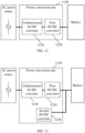
- FIG. 12 shows a schematic structural block diagram of the power conversion unit 1120 provided by the embodiments of the present application.
- the power conversion unit 1120 may be connected to an alternating current (AC) power source and a battery, where the power conversion unit 1120 includes a unidirectional alternating current/direct current (AC/DC) converter 1210 and a first direct current/direct current (DC/DC) converter 1220.
- the first DC/DC converter 1220 is a unidirectional DC/DC converter.
- a first end of the unidirectional AC/DC converter 1210 may be connected to an AC power source, a second end of the unidirectional AC/DC converter 1210 may be connected to a first end of the first DC/DC converter 1220, and a second end of the first DC/DC converter 1220 may be connected to a battery to achieve current transfer between the battery and the AC power source.
- the BMS may send a first charging current to the control unit 1110, and accordingly, the control unit 1110 may be used for receiving the first charging current sent by the BMS and control the unidirectional AC/DC converter 1210 and the first DC/DC converter 1220 based on the first charging current to charge the battery through by the AC power source.
- the BMS may send a first discharging current to the control unit 1110, which may be used for receiving the first discharging current and controlling the battery to release power based on the first discharging current.
- the charging and discharging device can realize charging and discharging the battery based on the first charging current and the first discharging current sent by the BMS, thereby avoiding continuous charging of the battery, thereby avoiding problems such as heating and lithium ion accumulation caused by continuous charging of the battery.
- heating will cause the temperature of the battery to rise, crystals produced by lithium ion accumulation may puncture the battery, causing electrolyte leakage and short circuit of the battery.
- the temperature rise and short circuit of the battery may cause safety problems of the battery, such as burning or explosion of the battery.
- the charging and discharging device realizes the charging and discharging of the battery based on the first charging current and the first discharging current sent by the BMS, which can ensure the safety performance of the battery.
- the continuous aggregation of lithium ions will also cause lithium precipitation problems, which will affect the service life and charge capacity of the battery. Therefore, charging and discharging device can also ensure the service life and charge capacity of the battery.
- the charging and discharging device includes a unidirectional AC/DC converter and a unidirectional DC/DC converter, namely, the structure of the charging and discharging device of the embodiments of the application is the same as that of the existing charging pile, that is to say, the charging and discharging of the battery can be realized without changing the prior charging pile structure, and the charging cost is greatly reduced.
- control unit 1110 may also be used for receiving the second charging current sent by the BMS and control the unidirectional AC/DC converter 1210 and the first DC/DC converter 1220 to charge the battery through the AC power source based on the second charging current.
- control unit 1110 When the control unit 1110 controls the unidirectional AC/DC converter 1210 and the first DC/DC converter 1220 to charge a battery through the AC power source, the control unit 1110 may sequentially control the unidirectional AC/DC converter 1210 and the first DC/DC converter 1220.
- the BMS may also send a second discharging current to the control unit 1110, and accordingly, the control unit 1110 may also be used for receiving the second discharging current sent by the BMS and controlling the battery release power based on the second discharging current.
- the BMS may send a charge stop command to the control unit 1110, which is used for instructing the charging and discharging device to stop charging the battery.
- the control unit 1110 is used for receiving a charge stop command sent by the BMS, and based on the charge stop command, controlling the unidirectional AC/DC converter 1210 and the first DC/DC converter 1220 so that the AC power source stops charging the battery.
- the control unit controls the AC/DC converter and the first DC/DC converter by receiving the charge stop command to make the AC power source stop charging the battery, thus preventing the battery from overcharging and further ensuring the safety performance of the battery.
- the power conversion unit 1120 may also include a second DC/DC converter 1230.
- the second end of the second DC/DC converter 1230 may be connected to the battery and the second end of the first DC/DC converter 1220, respectively.
- control unit 1100 may specifically be used for controlling the second DC/DC converter 1230 to release the power of the battery into the energy storage unit based on the first discharging current.
- the power of the battery is released into the energy storage unit, so that the energy storage unit can perform other operations based on the received power, thus avoiding the waste of power.
- the energy storage unit may be a low-power energy storage unit.
- the energy storage unit may be a super battery or a lithium carbonate battery.
- the cost of the charging system can be reduced.
- the energy storage unit may be provided independently of the charging and discharging device 1110, or the charging and discharging device 1110 may also include the energy storage unit.
- the charging and discharging device includes an energy storage unit, as shown in FIG. 14
- the energy storage unit may be a part of the power conversion unit 1120, or may be a unit independent of the power conversion unit 1120 and connected to the power conversion unit 1120 through a wire, which is not specifically limited in the embodiments of the present application.
- a first end of the unidirectional AC/DC converter 1210 is connected to an AC power source, a second end is connected to a first end of the first DC/DC converter 1220, the second end of the first DC/DC converter 1220 is respectively connected to a battery and a second end of the second DC/DC converter 1230, and the first end of the second DC/DC converter 1230 is connected to an energy storage unit 1240.
- control unit 1110 may control the unidirectional AC/DC converter 1210 and the first DC/DC converter 1220 to turn off the mode of charging the battery, and control the second DC/DC converter 1230 to turn on the mode of discharging the energy storage unit 1240.
- the second DC/DC converter 1230 may be a unidirectional DC/DC converter.
- the second DC/DC converter 1230 may be a bidirectional DC/DC converter.
- control unit 1110 may control the second DC/DC converter 1230 to charge the battery through the energy storage unit 1240 while controlling the unidirectional AC/DC converter 1210 and the first DC/DC converter 1220 to charge the battery through the AC power source based on the first charging current.
- control unit 1110 may also control the second DC/DC converter 1230 to charge the battery through the energy storage unit 1240 while controlling the unidirectional AC/DC converter 1210 and the first DC/DC converter 1220 to charge the battery through the AC power source based on the second charging current.
- the first charging current and the current at which the energy storage unit 1240 charges the battery may be different, and similarly, the second charging current may be different from the current at which the energy storage unit 1240 charges the battery.
- the first charging current may be greater than the current at which the energy storage unit 1240 charges the battery.
- the charging rate at which the energy storage unit 1240 charges the battery may be less than 0.5 C1, C1 is the capacity of the energy storage unit 1240.
- control unit 1110 may control the unidirectional AC/DC converter 1210 and the first DC/DC converter 1220 to charge the battery through an AC power source, and control the second DC/DC converter 1230 to charge the battery through the energy storage unit 1240.
- control unit 1110 may first acquire the SOC of the energy storage unit 1240, and then determine the AC power source to charge the battery based on the SOC of the energy storage unit 1240, or determine that the AC power source and the energy storage unit 1240 charge the battery simultaneously based on the SOC of the energy storage unit 1240.
- the energy storage unit 1240 may send a first message including the SOC of the energy storage unit 1240 to the control unit 1110, so that the control unit 1110 may acquire the SOC of the energy storage unit 1240.
- the energy storage unit 1240 may store the SOC to the cloud such that the control unit 1110 may acquire the SOC of the energy storage unit 1240 from the cloud.
- control unit 1110 may control not only the unidirectional AC/DC converter 1210 and the first DC/DC converter 1220 to charge the battery through the AC power source, but also the second DC/DC converter 1230 to charge the battery through the energy storage unit 1240.
- the control unit 1110 may control only the unidirectional AC/DC converter 1210 and the first DC/DC converter 1220 to charge the battery through the AC power source.
- the control unit 1110 may send a charging request message to other devices to cause other devices to charge the energy storage unit 1240 until the SOC of the energy storage unit 1240 is greater than or equal to the state of charge threshold. After that, the AC power source and the energy storage unit 1240 can charge the battery at the same time.
- the state of charge threshold can be a fixed value.
- the state of charge threshold can be a variable.
- the state of charge threshold can vary with time, environment (such as temperature) and other factors.
- the state of charge threshold may be preset on the control unit 1110 or may be sent to the control unit 1110 by the energy storage unit.
- whether the energy storage unit is used to assist the AC power source to charge the battery together is determined according to the SOC of the energy storage unit, so that the charging efficiency of the charging and discharging device can be improved when the power stored by the energy storage unit is sufficient.
- the first charging power for charging the battery by the energy storage unit 1240 is W1
- the second charging power for charging the battery by the AC power source is W2
- W3 is a difference between the charging demand power of the battery and W1.
- the first charging power W1 may be determined prior to the second charging power W2.
- W1 may be determined according to the discharge capability of the energy storage unit 1240. In addition, W1 may also be determined according to the state of the energy storage unit 1240 at the current time, for example, the ampere-hour of the energy storage unit 1240, the temperature of the energy storage unit 1240, and the like.
- the AC power source includes, but is not limited to, a power grid that can be used to provide three-phase AC power, and the power grid can not only provide enough power to charge the battery, but also receive more power released by the battery.
- the AC power source may also be a single-phase AC power source.
- Embodiments of the present application are not limited to specific types of AC power sources.
- FIG. 15 illustrates a schematic flow diagram of a method 1500 for charging battery of embodiments of the present application.
- the method 1500 may be applied to a charging and discharging device including a first direct current/direct current DC/DC converter and a unidirectional alternating current/direct current AC/DC converter, for example, may be applied to a charging and discharging device including a unidirectional AC/DC converter 1210 and a first DC/DC converter 1220 in FIG. 12 .
- a charging and discharging device including a unidirectional AC/DC converter 1210 and a first DC/DC converter 1220 in FIG. 12 .
- method embodiments and device embodiments correspond to each other, and the similar descriptions may refer to the device embodiments.
- the method 1500 for charging battery 1500 may include the following steps:
- the method 1500 further includes receiving a second discharging current sent by the BMS, and controlling the battery to release power based on the second discharging current, where the second discharging current is a discharging current sent by the BMS when a second cumulative charge amount of the battery is greater than or equal to a second cumulative charge amount threshold and the voltage of the battery cell of the battery does not exceed the full charge voltage of the battery cell.
- the method 1500 further includes receiving a charge stop command sent by the BMS; and controlling, based on the charge stop command, the unidirectional AC/DC converter and the first DC/DC converter to cause the AC power source to stop charging the battery, where the charge stop command is a command sent by the BMS when the voltage of the battery cell of the battery exceeds the full charge voltage.
- the charging and discharging device further includes a second DC/DC converter such as the second DC/DC converter 1230 in FIGS. 13 and 14 .
- Controlling the battery to release power based on the first discharging current includes controlling the second DC/DC converter to release the power of the battery into an energy storage unit based on the first discharging current.
- the second DC/DC converter is a bidirectional DC/DC converter
- the method 1500 further includes controlling the second DC/DC converter to charge the battery through the energy storage unit while controlling the unidirectional AC/DC converter and the first DC/DC converter to charge the battery through the AC power source based on the first charging current; and/or controlling the second DC/DC converter to charge the battery through the energy storage unit when controlling the unidirectional AC/DC converter and the first DC/DC converter to charge the battery through the AC power source based on the second charging current.
- a first charging power of the energy storage unit to charge the battery is determined according to a discharge capability of the energy storage unit, and a second charging power of the AC power source to charge the battery is a difference between a charging demand power of the battery and the first charging power.
- charging the battery includes: acquiring a battery state of charge SOC value of the energy storage unit; under a condition that the SOC is greater than a SOC threshold, controlling the second DC/DC converter to charge the battery through the energy storage unit, and controlling the unidirectional AC/DC converter and the first DC/DC converter to charge the battery through the AC power source based on the first charging current; and/or under a condition that the SOC is greater than a SOC threshold, controlling the second DC/DC converter to charge the battery through the energy storage unit and controlling the unidirectional AC/DC converter, the first DC/DC converter to charge the battery through the AC power source based on the second charging current.
- the charging rate of the first charging current and/or the second charging current ranges from 2C to 10C.
- the discharging rate of the first discharging current ranges from 0.1 C to 1 C.
- the ratio of the first cumulative discharge amount threshold to the first cumulative charge amount threshold is less than or equal to 10%.
- At least one of the first charging current, the first discharging current, and the second charging current is determined according to a state parameter of the battery; where the state parameter of the battery includes at least one of a battery temperature, a battery voltage, a battery current, a battery state of charge, and a battery state of health.
- receiving a first charging current sent by the BMS of the battery includes periodically receiving the first charging current sent by the BMS; and/or, receiving the first discharging current sent by the BMS includes: periodically receiving the first discharging current sent by the BMS; and/or, receiving the second charging current sent by the BMS includes periodically receiving the second charging current sent by the BMS.
- the method 1500 further includes receiving a first charging voltage sent by the BMS, where the first charging voltage and the first charging current are carried in the first BCL message; and/or receiving a first discharging voltage sent by the BMS, where the first discharging voltage and the first discharging current are carried in the second BCL message; and/or, receiving a second charging voltage sent by the BMS, where the second charging voltage and the second charging current are carried in the third BCL message.
- FIG. 16 shows a schematic structural block diagram of an electronic device 1600 of one embodiment of the present application.
- the electronic device 1600 includes a memory 1610 and a processor 1620.
- the memory 1610 is used for storing a computer program
- the processor 1620 is used for reading the computer program and executing the methods of various embodiments of the present application described above based on the computer program.
- the electronic device 1600 may be used for any one or more of a BMS and a charge-discharge device.
- the processor in the BMS in addition to the processor in the charging and discharging device reading the corresponding computer program and executing the charging method corresponding to the charging and discharging device in the aforementioned various embodiments based on the computer program, the processor in the BMS can also read the corresponding computer program and execute the charging method corresponding to the BMS in the aforementioned various embodiments based on the computer program.
- the embodiment of the present application also provides a readable storage medium for storing a computer program, and the computer program is used for executing the aforementioned methods of various embodiments of the present application.
- the computer program may be a computer program in the charging and discharging device and/or BMS.
- serial number of each process does not mean the sequence of execution, and the execution sequence of each process should be determined by its function and internal logic, and should not constitute any limitation on the implementation process of the embodiments of the present application.
Landscapes
- Engineering & Computer Science (AREA)
- Power Engineering (AREA)
- Mechanical Engineering (AREA)
- Transportation (AREA)
- Life Sciences & Earth Sciences (AREA)
- Sustainable Energy (AREA)
- Sustainable Development (AREA)
- Chemical & Material Sciences (AREA)
- General Chemical & Material Sciences (AREA)
- Electrochemistry (AREA)
- Chemical Kinetics & Catalysis (AREA)
- Manufacturing & Machinery (AREA)
- Microelectronics & Electronic Packaging (AREA)
- Charge And Discharge Circuits For Batteries Or The Like (AREA)
- Secondary Cells (AREA)
Claims (12)
- Lade- und Entladevorrichtung, wobei die Lade- und Entladevorrichtung eine Ladesäule ist, wobei die Lade- und Entladevorrichtung einen ersten Gleichstrom-Gleichstrom-Wandler, DC-DC-Wandler, (1220) einen unidirektionalen Wechselstrom-Gleichstrom-Wandler, AC-DC-Wandler, (1210) und eine Steuereinheit umfasst, wobei der erste DC-DC-Wandler (1220) ein unidirektionaler DC-DC-Wandler ist und die Steuereinheit für Folgendes konfiguriert ist:Empfangen eines ersten Ladestroms, der von einem Batterieverwaltungssystem, BMS, einer Batterie gesendet wird, und Steuern des unidirektionalen AC-DC-Wandlers (1210) und des ersten DC-DC-Wandlers (1220), die Batterie über eine Wechselstrom-, AC-, Leistungsquelle basierend auf dem ersten Ladestrom zu laden, wobei die Batterie ein Power-Akku ist,Empfangen eines ersten Entladestroms, der von dem BMS gesendet wird, und Steuern der Batterie basierend auf dem ersten Entladestrom Leistung abzugeben, wobei der erste Entladestrom ein Entladestrom ist, der von dem BMS gesendet wird, wenn ein erster kumulativer Ladeumfang der Batterie größer oder gleich einem Schwellenwert des ersten kumulativen Ladeumfangs ist und eine Spannung einer Batteriezelle der Batterie eine Vollladespannung der Batteriezelle nicht übersteigt, undEmpfangen eines zweiten Ladestroms, der von dem BMS gesendet wird, und Steuern des unidirektionalen AC-DC-Wandlers (1210) und des ersten DC-DC-Wandlers (1220), die Batterie über die AC-Leistungsquelle basierend auf dem zweiten Ladestrom zu laden, wobei der zweite Ladestrom ein Ladestrom ist, der von dem BMS gesendet wird, wenn ein erster kumulativer Entladeumfang der Batterie größer oder gleich einem Schwellenwert des ersten kumulativen Entladeumfangs ist,wobei ein erstes Ende des unidirektionalen AC-DC-Wandlers (1210) mit einer AC-Leistungsquelle verbunden ist, ein zweites Ende des unidirektionalen AC-DC-Wandlers (1210) mit einem ersten Ende des ersten DC-DC-Wandlers (1220) verbunden ist und ein zweites Ende des ersten DC-DC-Wandlers (1220) mit der Batterie verbunden ist,wobei die Lade- und Entladevorrichtung ferner einen zweiten DC-DC-Wandler (1230) umfasst unddie Steuereinheit speziell für Folgendes konfiguriert ist:Steuern des zweiten DC-DC-Wandlers (1230), die Leistung der Batterie in eine Energiespeichereinheit abzugeben, basierend auf dem ersten Entladestrom,wobei ein zweites Ende des zweiten DC-DC-Wandlers (1230) mit der Batterie und dem zweiten Ende des ersten DC-DC-Wandlers (1220) verbunden ist und ein erstes Ende des zweiten DC-DC-Wandlers (1230) mit einer Energiespeichereinheit verbunden ist.
- Lade- und Entladevorrichtung nach Anspruch 1, wobei die Steuereinheit ferner für Folgendes konfiguriert ist:Empfangen eines zweiten Entladestroms, der von dem BMS gesendet wird, und Steuern der Batterie, Leistung abzugeben, basierend auf dem zweiten Entladestrom, wobei der zweite Entladestrom ein Entladestrom ist, der von dem BMS gesendet wird, wenn ein zweiter kumulativer Ladeumfang der Batterie größer oder gleich einem Schwellenwert des zweiten kumulativen Ladeumfangs ist und die Spannung der Batteriezelle der Batterie eine Vollladespannung der Batteriezelle nicht übersteigt.
- Lade- und Entladevorrichtung nach Anspruch 1 oder 2, wobei die Steuereinheit ferner für Folgendes konfiguriert ist:Empfangen eines Ladestoppbefehls, der von dem BMS gesendet wird, undSteuern des unidirektionalen AC-DC-Wandlers (1210) und des ersten DC-DC-Wandlers (1220), die AC-Leistungsquelle zu veranlassen, das Laden der Batterie zu stoppen, basierend auf dem Ladestoppbefehl, wobei der Ladestoppbefehl ein Befehl ist, der von dem BMS gesendet wird, wenn die Spannung der Batteriezelle der Batterie die Vollladespannung übersteigt.
- Lade- und Entladevorrichtung nach einem der Ansprüche 1 bis 3, wobei der zweite DC-DC-Wandler (1230) ein bidirektionaler DC-DC-Wandler ist und die Steuereinheit ferner für Folgendes konfiguriert ist:Steuern des zweiten DC-DC-Wandlers, die Batterie über die Energiespeichereinheit zu laden, während der unidirektionale AC-DC-Wandler (1210) und der erste DC-DC-Wandler (1220) gesteuert werden, die Batterie über die AC-Leistungsquelle zu laden, basierend auf dem ersten Ladestrom, und/oderSteuern des zweiten DC-DC-Wandlers, die Batterie über die Energiespeichereinheit zu laden, während der unidirektionale AC-DC-Wandler (1210) und der erste DC-DC-Wandler (1220) gesteuert werden, die Batterie über die AC-Leistungsquelle zu laden, basierend auf dem zweiten Ladestrom, und/oderwobei eine erste Ladeleistung der Energiespeichereinheit zum Laden der Batterie gemäß einem Entladevermögen der Energiespeichereinheit bestimmt wird und eine zweite Ladeleistung der AC-Leistungsquelle zum Laden der Batterie eine Differenz zwischen einem Bedarf an Ladeleistung der Batterie und der ersten Ladeleistung ist.
- Lade- und Entladevorrichtung nach Anspruch 4, wobei die Steuereinheit speziell für Folgendes konfiguriert ist:Erfassen eines Batterieladezustandes (SOC) der Energiespeichereinheit,unter einer Bedingung, dass der SOC größer als ein SOC-Schwellenwert ist, Steuern des zweiten DC-DC-Wandlers (1230), die Batterie über die Energiespeichereinheit zu laden, und Steuern des unidirektionalen AC-DC-Wandlers (1210) und des ersten DC-DC-Wandlers (1220), die Batterie über die AC-Leistungsquelle zu laden, basierend auf dem ersten Ladestrom, und/oderunter einer Bedingung, dass der SOC größer als ein SOC-Schwellenwert ist, Steuern des zweiten DC-DC-Wandlers (1230), die Batterie über die Energiespeichereinheit zu laden, und Steuern des unidirektionalen AC-DC-Wandlers (1210) und des ersten DC-DC-Wandlers (1220), die Batterie über die AC-Leistungsquelle zu laden, basierend auf dem zweiten Ladestrom.
- Lade- und Entladevorrichtung nach einem der Ansprüche 1 bis 5, wobei eine Laderate des ersten Ladestroms und/oder des zweiten Ladestroms im Bereich von 2 C bis 10 C liegt und/odereine Entladerate des ersten Entladestroms im Bereich von 0,1 C bis 1 C liegt und/oderein Verhältnis des Schwellenwertes des ersten kumulativen Entladeumfangs zu dem Schwellenwert des ersten kumulativen Ladeumfangs kleiner oder gleich 10 % ist.
- Verfahren zum Laden einer Batterie, wobei das Verfahren in einer Lade- und Entladevorrichtung angewandt wird, wobei die Lade- und Entladevorrichtung eine Ladesäule ist, wobei die Lade- und Entladevorrichtung einen ersten Gleichstrom-Gleichstrom-Wandler, DC-DC-Wandler, (1220) einen unidirektionalen Wechselstrom-Gleichstrom-Wandler, AC-DC-Wandler, (1210) umfasst, wobei der erste DC-DC-Wandler (1220) ein unidirektionaler DC-DC-Wandler ist, und Folgendes umfassend:Empfangen eines ersten Ladestroms, der von einem Batterieverwaltungssystem, BMS, einer Batterie gesendet wird, und Steuern des unidirektionalen AC-DC-Wandlers (1210), und des ersten DC-DC-Wandlers (1220), die Batterie über eine Wechselstrom-, AC-, Leistungsquelle basierend auf dem ersten Ladestrom zu laden, wobei die Batterie ein Power-Akku ist,Empfangen eines ersten Entladestroms, der von dem BMS gesendet wird, und Steuern der Batterie, basierend auf dem ersten Entladestrom Leistung abzugeben, wobei der erste Entladestrom ein Entladestrom ist, der von dem BMS gesendet wird, wenn ein erster kumulativer Ladeumfang der Batterie größer oder gleich einem Schwellenwert des ersten kumulativen Ladeumfangs ist und eine Spannung einer Batteriezelle der Batterie eine Vollladespannung der Batteriezelle nicht übersteigt, undEmpfangen eines zweiten Ladestroms, der von dem BMS gesendet wird, und Steuern des unidirektionalen AC-DC-Wandlers (1210) und des ersten DC-DC-Wandlers (1220), die Batterie über die AC-Leistungsquelle basierend auf dem zweiten Ladestrom zu laden, wobei der zweite Ladestrom ein Ladestrom ist, der von dem BMS gesendet wird, wenn ein erster kumulativer Entladeumfang der Batterie größer oder gleich einem Schwellenwert des ersten kumulativen Entladeumfangs ist,wobei ein erstes Ende des unidirektionalen AC-DC-Wandlers (1210) mit einer AC-Leistungsquelle verbunden wird, ein zweites Ende des unidirektionalen AC-DC-Wandlers (1210) mit einem ersten Ende des ersten DC-DC-Wandlers (1220) verbunden ist und ein zweites Ende des ersten DC-DC-Wandlers (1220) mit der Batterie verbunden ist,wobei die Lade- und Entladevorrichtung ferner einen zweiten DC-DC-Wandler (1230) umfasst und wobei das Steuern der Batterie, Energie abzugeben, basierend auf dem ersten Entladestrom, Folgendes umfasst:Steuern des zweiten DC-DC-Wandlers (1230), die Leistung der Batterie in eine Energiespeichereinheit abzugeben, basierend auf dem ersten Entladestrom,wobei ein zweites Ende des zweiten DC-DC-Wandlers (1230) mit der Batterie und dem zweiten Ende des ersten DC-DC-Wandlers (1220) verbunden wird und ein erstes Ende des zweiten DC-DC-Wandlers (1230) mit einer Energiespeichereinheit verbunden wird.
- Verfahren nach Anspruch 7, wobei das Verfahren ferner Folgendes umfasst:
Empfangen eines zweiten Entladestroms, der von dem BMS gesendet wird, und Steuern der Batterie, Leistung abzugeben, basierend auf dem zweiten Entladestrom, wobei der zweite Entladestrom ein Entladestrom ist, der von dem BMS gesendet wird, wenn ein zweiter kumulativer Ladeumfang der Batterie größer oder gleich einem Schwellenwert des zweiten kumulativen Ladeumfangs ist und die Spannung der Batteriezelle der Batterie die Vollladespannung der Batteriezelle nicht übersteigt. - Verfahren nach Anspruch 7 oder 8, wobei das Verfahren ferner Folgendes umfasst:Empfangen eines Ladestoppbefehls, der von dem BMS gesendet wird, undSteuern des unidirektionalen AC-DC-Wandlers (1210) und des ersten DC-DC-Wandlers (1220), die AC-Leistungsquelle zu veranlassen, das Laden der Batterie zu stoppen, basierend auf dem Ladestoppbefehl, wobei der Ladestoppbefehl ein Befehl ist, der von dem BMS gesendet wird, wenn die Spannung der Batteriezelle der Batterie die Vollladespannung übersteigt.
- Verfahren nach einem der Ansprüche 7 bis 9, wobei der zweite DC-DC-Wandler (1230) ein bidirektionaler DC-DC-Wandler ist und wobei das Verfahren ferner Folgendes umfasst:Steuern des zweiten DC-DC-Wandlers (1230), die Batterie über die Energiespeichereinheit zu laden, während der unidirektionale AC-DC-Wandler (1210) und der erste DC-DC-Wandler (1220) gesteuert werden, die Batterie über die AC-Leistungsquelle basierend auf dem ersten Ladestrom zu laden, und/oderSteuern des zweiten DC-DC-Wandlers (1230), die Batterie über die Energiespeichereinheit basierend auf dem ersten Ladestrom zu laden, während der unidirektionale AC-DC-Wandler (1210) und der erste DC-DC-Wandler (1220) gesteuert werden, die Batterie über die AC-Leistungsquelle basierend auf dem zweiten Ladestrom zu laden, und/oderwobei eine erste Ladeleistung der Energiespeichereinheit zum Laden der Batterie gemäß einem Entladevermögen der Energiespeichereinheit bestimmt wird, und eine zweite Ladeleistung der AC-Leistungsquelle zum Laden der Batterie eine Differenz zwischen einem Bedarf an Ladeleistung der Batterie und der ersten Ladeleistung ist.
- Verfahren nach Anspruch 10, wobei das Laden der Batterie Folgendes umfasst:Erfassen eines Batterieladezustandes (SOC) der Energiespeichereinheit,unter einer Bedingung, dass der SOC größer als ein SOC-Schwellenwert ist, Steuern des zweiten DC-DC-Wandlers (1230), die Batterie über die Energiespeichereinheit zu laden, und Steuern des unidirektionalen AC-DC-Wandlers (1210) und des ersten DC-DC-Wandlers (1220), die Batterie über die AC-Leistungsquelle zu laden, basierend auf dem ersten Ladestrom, und/oderunter einer Bedingung, dass der SOC, größer als ein SOC-Schwellenwert ist, Steuern des zweiten DC-DC-Wandlers (1230), die Batterie über die Energiespeichereinheit zu laden, und Steuern des unidirektionalen AC-DC-Wandlers (1210) und des ersten DC-DC-Wandlers (1220), die Batterie über die AC-Leistungsquelle zu laden, basierend auf dem zweiten Ladestrom.
- Verfahren nach einem der Ansprüche 7 bis 11, wobei eine Laderate des ersten Ladestroms und/oder des zweiten Ladestroms im Bereich von 2 C bis 10 C liegt und/odereine Entladerate des ersten Entladestroms im Bereich von 0,1 C bis 1 C liegt und/oderein Verhältnis des Schwellenwertes des ersten kumulativen Entladeumfangs zu dem Schwellenwert des ersten kumulativen Ladeumfangs kleiner oder gleich 10 % ist.
Priority Applications (1)
| Application Number | Priority Date | Filing Date | Title |
|---|---|---|---|
| HUE21819322A HUE069054T2 (hu) | 2021-07-29 | 2021-07-29 | Akkumulátortöltési eljárás, valamint töltõ- és merítõberendezés |
Applications Claiming Priority (1)
| Application Number | Priority Date | Filing Date | Title |
|---|---|---|---|
| PCT/CN2021/109367 WO2023004709A1 (zh) | 2021-07-29 | 2021-07-29 | 电池充电的方法和充放电装置 |
Publications (5)
| Publication Number | Publication Date |
|---|---|
| EP4152552A1 EP4152552A1 (de) | 2023-03-22 |
| EP4152552A4 EP4152552A4 (de) | 2023-03-22 |
| EP4152552C0 EP4152552C0 (de) | 2024-09-04 |
| EP4152552B1 true EP4152552B1 (de) | 2024-09-04 |
| EP4152552B8 EP4152552B8 (de) | 2024-10-16 |
Family
ID=85037996
Family Applications (1)
| Application Number | Title | Priority Date | Filing Date |
|---|---|---|---|
| EP21819322.5A Active EP4152552B8 (de) | 2021-07-29 | 2021-07-29 | Batterieladeverfahren und lade- und entladevorrichtung |
Country Status (8)
| Country | Link |
|---|---|
| US (1) | US12051934B2 (de) |
| EP (1) | EP4152552B8 (de) |
| JP (1) | JP7450645B2 (de) |
| KR (1) | KR102801326B1 (de) |
| CN (1) | CN116325420B (de) |
| ES (1) | ES2996459T3 (de) |
| HU (1) | HUE069054T2 (de) |
| WO (1) | WO2023004709A1 (de) |
Families Citing this family (6)
| Publication number | Priority date | Publication date | Assignee | Title |
|---|---|---|---|---|
| JP7431866B2 (ja) * | 2021-07-29 | 2024-02-15 | 寧徳時代新能源科技股▲分▼有限公司 | 充放電装置、電池充電方法及び充放電システム |
| WO2023035161A1 (zh) * | 2021-09-08 | 2023-03-16 | 宁德时代新能源科技股份有限公司 | 动力电池充电的方法和电池管理系统 |
| US20250096336A1 (en) * | 2022-03-28 | 2025-03-20 | Iontra Inc | Electrodynamic parameters |
| CN115764950A (zh) * | 2022-10-27 | 2023-03-07 | 北京交通大学 | 轨道交通储能系统的控制方法、模型、设备和存储介质 |
| US12202371B2 (en) * | 2022-12-22 | 2025-01-21 | Speed Charge, Llc | Dynamic output control of vehicle chargers with respective internal batteries |
| CN117445740B (zh) * | 2023-10-31 | 2024-10-22 | 上汽通用五菱汽车股份有限公司 | 充电方法、装置、系统、控制器以及存储介质 |
Citations (1)
| Publication number | Priority date | Publication date | Assignee | Title |
|---|---|---|---|---|
| CN108110349A (zh) * | 2017-12-15 | 2018-06-01 | 宁德时代新能源科技股份有限公司 | 一种电池充电的方法及装置、计算机可读存储介质 |
Family Cites Families (16)
| Publication number | Priority date | Publication date | Assignee | Title |
|---|---|---|---|---|
| CN101617454B (zh) | 2007-02-19 | 2012-10-10 | 株式会社能量应用技术研究所 | 快速充电用供电装置以及快速充电用供电方法 |
| CN102422504A (zh) * | 2009-05-18 | 2012-04-18 | 波士顿电力公司 | 可充电电池的能量效率及快速充电模式 |
| JP5016121B2 (ja) * | 2010-02-19 | 2012-09-05 | Jfeエンジニアリング株式会社 | 急速充電装置及び移動式充電装置 |
| DE102011087496A1 (de) * | 2011-11-30 | 2013-06-27 | H-Tech Ag | Verfahren und Vorrichtung zum Laden von wiederaufladbaren Zellen |
| KR20150108825A (ko) * | 2013-01-21 | 2015-09-30 | 가부시키가이샤 한도오따이 에네루기 켄큐쇼 | 2차 전지, 2차 전지 모듈, 2차 전지 및 2차 전지 모듈의 충전 방법, 2차 전지 및 2차 전지 모듈의 방전 방법, 2차 전지 및 2차 전지 모듈의 구동 방법, 축전 시스템, 및 축전 시스템의 구동 방법 |
| US10040363B2 (en) * | 2015-10-15 | 2018-08-07 | Powin Energy Corporation | Battery-assisted electric vehicle charging system and method |
| KR102572647B1 (ko) * | 2016-02-25 | 2023-08-31 | 삼성에스디아이 주식회사 | 배터리 팩 |
| CN106374559B (zh) * | 2016-09-14 | 2021-08-20 | 华为技术有限公司 | 串联电池组的快速充电方法及相关设备 |
| US10491025B1 (en) * | 2017-07-19 | 2019-11-26 | Facebook, Inc. | Apparatus, systems, and methods for pulse charging rechargeable batteries |
| CN207368673U (zh) * | 2017-09-15 | 2018-05-15 | 深圳市福正达新能源科技有限公司 | 一种锂电池化成设备 |
| CN108032740A (zh) * | 2017-10-24 | 2018-05-15 | 合肥成科电子科技有限公司 | 一种储能式电动汽车充电桩系统 |
| CN207442505U (zh) | 2017-11-14 | 2018-06-01 | 宁波三星智能电气有限公司 | 一种储能式充电桩 |
| CN110445233A (zh) * | 2018-05-04 | 2019-11-12 | 乐金电子研发中心(上海)有限公司 | 一种具有宽范围输出电压的车载充电装置 |
| CN108528263A (zh) * | 2018-06-08 | 2018-09-14 | 重庆聚陆新能源有限公司 | 一种高效率的电动汽车直流快充系统 |
| WO2020124521A1 (zh) * | 2018-12-21 | 2020-06-25 | 深圳市大疆创新科技有限公司 | 对锂电池进行充电的方法及相关装置 |
| CN111381171A (zh) * | 2018-12-28 | 2020-07-07 | 天津银隆新能源有限公司 | 基于燃料电池测试的微网系统及控制方法 |
-
2021
- 2021-07-29 JP JP2021575015A patent/JP7450645B2/ja active Active
- 2021-07-29 HU HUE21819322A patent/HUE069054T2/hu unknown
- 2021-07-29 WO PCT/CN2021/109367 patent/WO2023004709A1/zh not_active Ceased
- 2021-07-29 ES ES21819322T patent/ES2996459T3/es active Active
- 2021-07-29 EP EP21819322.5A patent/EP4152552B8/de active Active
- 2021-07-29 KR KR1020217040290A patent/KR102801326B1/ko active Active
- 2021-07-29 CN CN202180070058.1A patent/CN116325420B/zh active Active
- 2021-12-28 US US17/563,513 patent/US12051934B2/en active Active
Patent Citations (1)
| Publication number | Priority date | Publication date | Assignee | Title |
|---|---|---|---|---|
| CN108110349A (zh) * | 2017-12-15 | 2018-06-01 | 宁德时代新能源科技股份有限公司 | 一种电池充电的方法及装置、计算机可读存储介质 |
Also Published As
| Publication number | Publication date |
|---|---|
| JP2023543097A (ja) | 2023-10-13 |
| US12051934B2 (en) | 2024-07-30 |
| EP4152552A1 (de) | 2023-03-22 |
| ES2996459T3 (en) | 2025-02-12 |
| EP4152552A4 (de) | 2023-03-22 |
| HUE069054T2 (hu) | 2025-02-28 |
| KR20230019379A (ko) | 2023-02-08 |
| KR102801326B1 (ko) | 2025-04-28 |
| EP4152552B8 (de) | 2024-10-16 |
| EP4152552C0 (de) | 2024-09-04 |
| WO2023004709A1 (zh) | 2023-02-02 |
| US20230031352A1 (en) | 2023-02-02 |
| CN116325420B (zh) | 2025-09-23 |
| JP7450645B2 (ja) | 2024-03-15 |
| CN116325420A (zh) | 2023-06-23 |
Similar Documents
| Publication | Publication Date | Title |
|---|---|---|
| EP4152552B1 (de) | Batterieladeverfahren und lade- und entladevorrichtung | |
| US20230035145A1 (en) | Method for charging battery, battery management system, charge and discharge device | |
| EP4220885B1 (de) | Lade-/entladevorrichtung, batterielade- und entladeverfahren und lade-/entladesystem | |
| US12266964B2 (en) | Charging-and-discharging apparatus, method for charging a battery and charging-and-discharging system | |
| EP4068561B1 (de) | Ladeverfahren und leistungswandlervorrichtung | |
| CN116508227A (zh) | 充放电装置和电池充电的方法 | |
| US20230034292A1 (en) | Charging and discharging apparatus, method for charging battery and charging and discharging system |
Legal Events
| Date | Code | Title | Description |
|---|---|---|---|
| STAA | Information on the status of an ep patent application or granted ep patent |
Free format text: STATUS: UNKNOWN |
|
| STAA | Information on the status of an ep patent application or granted ep patent |
Free format text: STATUS: THE INTERNATIONAL PUBLICATION HAS BEEN MADE |
|
| PUAI | Public reference made under article 153(3) epc to a published international application that has entered the european phase |
Free format text: ORIGINAL CODE: 0009012 |
|
| STAA | Information on the status of an ep patent application or granted ep patent |
Free format text: STATUS: REQUEST FOR EXAMINATION WAS MADE |
|
| 17P | Request for examination filed |
Effective date: 20211214 |
|
| A4 | Supplementary search report drawn up and despatched |
Effective date: 20221123 |
|
| AK | Designated contracting states |
Kind code of ref document: A1 Designated state(s): AL AT BE BG CH CY CZ DE DK EE ES FI FR GB GR HR HU IE IS IT LI LT LU LV MC MK MT NL NO PL PT RO RS SE SI SK SM TR |
|
| STAA | Information on the status of an ep patent application or granted ep patent |
Free format text: STATUS: EXAMINATION IS IN PROGRESS |
|
| 17Q | First examination report despatched |
Effective date: 20240102 |
|
| GRAP | Despatch of communication of intention to grant a patent |
Free format text: ORIGINAL CODE: EPIDOSNIGR1 |
|
| STAA | Information on the status of an ep patent application or granted ep patent |
Free format text: STATUS: GRANT OF PATENT IS INTENDED |
|
| DAV | Request for validation of the european patent (deleted) | ||
| DAX | Request for extension of the european patent (deleted) | ||
| INTG | Intention to grant announced |
Effective date: 20240603 |
|
| GRAS | Grant fee paid |
Free format text: ORIGINAL CODE: EPIDOSNIGR3 |
|
| GRAA | (expected) grant |
Free format text: ORIGINAL CODE: 0009210 |
|
| STAA | Information on the status of an ep patent application or granted ep patent |
Free format text: STATUS: THE PATENT HAS BEEN GRANTED |
|
| AK | Designated contracting states |
Kind code of ref document: B1 Designated state(s): AL AT BE BG CH CY CZ DE DK EE ES FI FR GB GR HR HU IE IS IT LI LT LU LV MC MK MT NL NO PL PT RO RS SE SI SK SM TR |
|
| REG | Reference to a national code |
Ref country code: GB Ref legal event code: FG4D |
|
| REG | Reference to a national code |
Ref country code: DE Ref legal event code: R081 Ref document number: 602021018457 Country of ref document: DE Owner name: CONTEMPORARY AMPEREX TECHNOLOGY (HONG KONG) LI, HK Free format text: FORMER OWNER: CONTEMPORARY AMPEREX TECHNOLOGY CO., LIMITED, NINGDE CITY, FUJIAN, CN Ref country code: CH Ref legal event code: EP |
|
| REG | Reference to a national code |
Ref country code: IE Ref legal event code: FG4D |
|
| REG | Reference to a national code |
Ref country code: DE Ref legal event code: R096 Ref document number: 602021018457 Country of ref document: DE |
|
| REG | Reference to a national code |
Ref country code: CH Ref legal event code: PK Free format text: BERICHTIGUNG B8 |
|
| RAP2 | Party data changed (patent owner data changed or rights of a patent transferred) |
Owner name: CONTEMPORARY AMPEREX TECHNOLOGY(HONG KONG) LIMITED |
|
| U01 | Request for unitary effect filed |
Effective date: 20240930 |
|
| U07 | Unitary effect registered |
Designated state(s): AT BE BG DE DK EE FI FR IT LT LU LV MT NL PT RO SE SI Effective date: 20241024 |
|
| PG25 | Lapsed in a contracting state [announced via postgrant information from national office to epo] |
Ref country code: GR Free format text: LAPSE BECAUSE OF FAILURE TO SUBMIT A TRANSLATION OF THE DESCRIPTION OR TO PAY THE FEE WITHIN THE PRESCRIBED TIME-LIMIT Effective date: 20241205 Ref country code: PL Free format text: LAPSE BECAUSE OF FAILURE TO SUBMIT A TRANSLATION OF THE DESCRIPTION OR TO PAY THE FEE WITHIN THE PRESCRIBED TIME-LIMIT Effective date: 20240904 |
|
| PG25 | Lapsed in a contracting state [announced via postgrant information from national office to epo] |
Ref country code: HR Free format text: LAPSE BECAUSE OF FAILURE TO SUBMIT A TRANSLATION OF THE DESCRIPTION OR TO PAY THE FEE WITHIN THE PRESCRIBED TIME-LIMIT Effective date: 20240904 |
|
| PG25 | Lapsed in a contracting state [announced via postgrant information from national office to epo] |
Ref country code: RS Free format text: LAPSE BECAUSE OF FAILURE TO SUBMIT A TRANSLATION OF THE DESCRIPTION OR TO PAY THE FEE WITHIN THE PRESCRIBED TIME-LIMIT Effective date: 20241204 |
|
| PG25 | Lapsed in a contracting state [announced via postgrant information from national office to epo] |
Ref country code: RS Free format text: LAPSE BECAUSE OF FAILURE TO SUBMIT A TRANSLATION OF THE DESCRIPTION OR TO PAY THE FEE WITHIN THE PRESCRIBED TIME-LIMIT Effective date: 20241204 Ref country code: PL Free format text: LAPSE BECAUSE OF FAILURE TO SUBMIT A TRANSLATION OF THE DESCRIPTION OR TO PAY THE FEE WITHIN THE PRESCRIBED TIME-LIMIT Effective date: 20240904 Ref country code: HR Free format text: LAPSE BECAUSE OF FAILURE TO SUBMIT A TRANSLATION OF THE DESCRIPTION OR TO PAY THE FEE WITHIN THE PRESCRIBED TIME-LIMIT Effective date: 20240904 Ref country code: GR Free format text: LAPSE BECAUSE OF FAILURE TO SUBMIT A TRANSLATION OF THE DESCRIPTION OR TO PAY THE FEE WITHIN THE PRESCRIBED TIME-LIMIT Effective date: 20241205 |
|
| REG | Reference to a national code |
Ref country code: ES Ref legal event code: FG2A Ref document number: 2996459 Country of ref document: ES Kind code of ref document: T3 Effective date: 20250212 |
|
| REG | Reference to a national code |
Ref country code: HU Ref legal event code: AG4A Ref document number: E069054 Country of ref document: HU |
|
| PG25 | Lapsed in a contracting state [announced via postgrant information from national office to epo] |
Ref country code: IS Free format text: LAPSE BECAUSE OF FAILURE TO SUBMIT A TRANSLATION OF THE DESCRIPTION OR TO PAY THE FEE WITHIN THE PRESCRIBED TIME-LIMIT Effective date: 20250104 |
|
| PG25 | Lapsed in a contracting state [announced via postgrant information from national office to epo] |
Ref country code: SM Free format text: LAPSE BECAUSE OF FAILURE TO SUBMIT A TRANSLATION OF THE DESCRIPTION OR TO PAY THE FEE WITHIN THE PRESCRIBED TIME-LIMIT Effective date: 20240904 |
|
| PG25 | Lapsed in a contracting state [announced via postgrant information from national office to epo] |
Ref country code: CZ Free format text: LAPSE BECAUSE OF FAILURE TO SUBMIT A TRANSLATION OF THE DESCRIPTION OR TO PAY THE FEE WITHIN THE PRESCRIBED TIME-LIMIT Effective date: 20240904 |
|
| PG25 | Lapsed in a contracting state [announced via postgrant information from national office to epo] |
Ref country code: SK Free format text: LAPSE BECAUSE OF FAILURE TO SUBMIT A TRANSLATION OF THE DESCRIPTION OR TO PAY THE FEE WITHIN THE PRESCRIBED TIME-LIMIT Effective date: 20240904 |
|
| PLBE | No opposition filed within time limit |
Free format text: ORIGINAL CODE: 0009261 |
|
| STAA | Information on the status of an ep patent application or granted ep patent |
Free format text: STATUS: NO OPPOSITION FILED WITHIN TIME LIMIT |
|
| PGFP | Annual fee paid to national office [announced via postgrant information from national office to epo] |
Ref country code: HU Payment date: 20250702 Year of fee payment: 5 |
|
| 26N | No opposition filed |
Effective date: 20250605 |
|
| U20 | Renewal fee for the european patent with unitary effect paid |
Year of fee payment: 5 Effective date: 20250722 |
|
| PGFP | Annual fee paid to national office [announced via postgrant information from national office to epo] |
Ref country code: ES Payment date: 20250801 Year of fee payment: 5 |
|
| PGFP | Annual fee paid to national office [announced via postgrant information from national office to epo] |
Ref country code: NO Payment date: 20250723 Year of fee payment: 5 |
|
| PGFP | Annual fee paid to national office [announced via postgrant information from national office to epo] |
Ref country code: GB Payment date: 20250722 Year of fee payment: 5 |