EP4152459A1 - End plate positioning device and battery module assembly apparatus - Google Patents
End plate positioning device and battery module assembly apparatus Download PDFInfo
- Publication number
- EP4152459A1 EP4152459A1 EP22793378.5A EP22793378A EP4152459A1 EP 4152459 A1 EP4152459 A1 EP 4152459A1 EP 22793378 A EP22793378 A EP 22793378A EP 4152459 A1 EP4152459 A1 EP 4152459A1
- Authority
- EP
- European Patent Office
- Prior art keywords
- end plate
- positioning
- pedestal
- piece
- hole
- Prior art date
- Legal status (The legal status is an assumption and is not a legal conclusion. Google has not performed a legal analysis and makes no representation as to the accuracy of the status listed.)
- Granted
Links
Images


Classifications
-
- H—ELECTRICITY
- H01—ELECTRIC ELEMENTS
- H01M—PROCESSES OR MEANS, e.g. BATTERIES, FOR THE DIRECT CONVERSION OF CHEMICAL ENERGY INTO ELECTRICAL ENERGY
- H01M10/00—Secondary cells; Manufacture thereof
- H01M10/04—Construction or manufacture in general
- H01M10/0404—Machines for assembling batteries
-
- H—ELECTRICITY
- H01—ELECTRIC ELEMENTS
- H01M—PROCESSES OR MEANS, e.g. BATTERIES, FOR THE DIRECT CONVERSION OF CHEMICAL ENERGY INTO ELECTRICAL ENERGY
- H01M10/00—Secondary cells; Manufacture thereof
- H01M10/04—Construction or manufacture in general
- H01M10/0413—Large-sized flat cells or batteries for motive or stationary systems with plate-like electrodes
-
- H—ELECTRICITY
- H01—ELECTRIC ELEMENTS
- H01M—PROCESSES OR MEANS, e.g. BATTERIES, FOR THE DIRECT CONVERSION OF CHEMICAL ENERGY INTO ELECTRICAL ENERGY
- H01M50/00—Constructional details or processes of manufacture of the non-active parts of electrochemical cells other than fuel cells, e.g. hybrid cells
- H01M50/20—Mountings; Secondary casings or frames; Racks, modules or packs; Suspension devices; Shock absorbers; Transport or carrying devices; Holders
- H01M50/262—Mountings; Secondary casings or frames; Racks, modules or packs; Suspension devices; Shock absorbers; Transport or carrying devices; Holders with fastening means, e.g. locks
- H01M50/264—Mountings; Secondary casings or frames; Racks, modules or packs; Suspension devices; Shock absorbers; Transport or carrying devices; Holders with fastening means, e.g. locks for cells or batteries, e.g. straps, tie rods or peripheral frames
-
- Y—GENERAL TAGGING OF NEW TECHNOLOGICAL DEVELOPMENTS; GENERAL TAGGING OF CROSS-SECTIONAL TECHNOLOGIES SPANNING OVER SEVERAL SECTIONS OF THE IPC; TECHNICAL SUBJECTS COVERED BY FORMER USPC CROSS-REFERENCE ART COLLECTIONS [XRACs] AND DIGESTS
- Y02—TECHNOLOGIES OR APPLICATIONS FOR MITIGATION OR ADAPTATION AGAINST CLIMATE CHANGE
- Y02E—REDUCTION OF GREENHOUSE GAS [GHG] EMISSIONS, RELATED TO ENERGY GENERATION, TRANSMISSION OR DISTRIBUTION
- Y02E60/00—Enabling technologies; Technologies with a potential or indirect contribution to GHG emissions mitigation
- Y02E60/10—Energy storage using batteries
-
- Y—GENERAL TAGGING OF NEW TECHNOLOGICAL DEVELOPMENTS; GENERAL TAGGING OF CROSS-SECTIONAL TECHNOLOGIES SPANNING OVER SEVERAL SECTIONS OF THE IPC; TECHNICAL SUBJECTS COVERED BY FORMER USPC CROSS-REFERENCE ART COLLECTIONS [XRACs] AND DIGESTS
- Y02—TECHNOLOGIES OR APPLICATIONS FOR MITIGATION OR ADAPTATION AGAINST CLIMATE CHANGE
- Y02P—CLIMATE CHANGE MITIGATION TECHNOLOGIES IN THE PRODUCTION OR PROCESSING OF GOODS
- Y02P70/00—Climate change mitigation technologies in the production process for final industrial or consumer products
- Y02P70/50—Manufacturing or production processes characterised by the final manufactured product
Definitions
- This application relates to the technical field of batteries, and in particular, to an end plate positioning apparatus and battery module assembling equipment.
- Battery cells are widely used in electronic devices such as a mobile phone, a notebook computer, an electric power cart, an electric vehicle, an electric airplane, an electric ship, an electric toy car, an electric toy ship, an electric toy airplane, and a power tool.
- the battery cells may include a nickel-cadmium battery cell, a nickel-hydrogen battery cell, a lithium-ion battery cell, a secondary alkaline zinc-manganese battery cell, and the like.
- This application provides an end plate positioning apparatus and battery module assembling equipment to improve precision of assembling battery modules.
- an embodiment of this application provides an end plate positioning apparatus, applicable to assembling of battery modules.
- the end plate positioning apparatus includes: a pedestal; a supporting piece, disposed on the pedestal and configured to hold an end plate; at least one first positioning mechanism, including a first positioning piece and a positioning locking piece, where the first positioning piece is rotatably connected to the pedestal, the positioning locking piece includes a guide portion and a slide portion, one of the guide portion or the slide portion is disposed on the first positioning piece, and the other is disposed on the pedestal; the guide portion includes a first position and a second position, and the slide portion is able to move between the first position and the second position to drive the first positioning piece to rotate; when the slide portion is located in the first position, the first positioning piece is in abutment with the end plate, so that the first positioning piece and the supporting piece clamp the end plate from both sides; and, when the slide portion is located in the second position, the first positioning piece is out of abutment with the end plate.
- the design of the first positioning mechanism can convert rotation into a movement in the third direction to implement positioning of the end plate, without occupying much space in the vertical third direction.
- the end plate positioning apparatus achieves the purpose of positioning the end plate in the limited space of the battery module assembling equipment, and implements positioning of the end plate in a height direction by fully utilizing the limited space in the vertical third direction, thereby avoiding the problem that the end plate is prone to be out of position in the height direction due to a considerable length of the placed end plate, and improving the positioning precision of the end plate.
- the first positioning piece includes a connecting rod and a hold-down bar.
- One end of the connecting rod is rotatably connected to the pedestal, and the other end is connected to the hold-down bar.
- the slide portion is connected to the connecting rod.
- the guide portion is movably connected to the pedestal. The guide portion is able to move relative to the pedestal along a first direction so that, when the slide portion is located in the first position, a length direction of the connecting rod is parallel to the first direction, the hold-down bar is in abutment with the end plate along a second direction, and the first direction intersects the second direction, and so that, when the slide portion is located in the second position, the length direction of the connecting rod is at a preset angle to the first direction.
- the end plate can be automatically brought into position and out of position at a relatively high precision, thereby reducing the positioning error caused by repeated changeover.
- the guide portion includes a guide slot.
- the slide portion includes a bulge extending into the guide slot. The bulge is slidably connected to the guide slot.
- a simple structural fit facilitates the changeover of the slide portion between the first position and the second position, thereby facilitating assembling.
- the fit between the bulge and the guide slot provides a guiding effect for the rotation of the connecting rod relative to the pedestal, thereby ensuring proper positioning of the end plate in the height direction.
- the guide slot includes at least a first hole and a second hole that communicate with each other.
- a connecting line of an axis of the first hole and an axis of the second hole is at a preset angle to the first direction.
- the length direction of the connecting rod is parallel to the first direction when the bulge is located in the first hole, and the length direction of the connecting rod is at the preset angle to the first direction when the bulge slides to the second hole.
- the preset angle by which the connecting rod is rotated can be adjusted through the fit between the bulge and the first hole or second hole, and the connecting rod can be controlled at a relatively high precision to rotate by an angle that changes over between an initial 0-degree angle and the preset angle, so as to ensure that the hold-down bar can implement efficient and quick positioning in the height direction on each occasion of positioning the end plate.
- the first hole and the second hole are through-holes, or, the first hole and the second hole are blind holes.
- the positioning locking piece further includes a first driving portion.
- the first driving portion is connected to the pedestal and is configured to drive the guide portion to move along the first direction.
- the movement in the first direction is converted into a desired movement in the second direction by the fit between the first driving portion, the slide portion, and the guide portion that are disposed, thereby implementing stable positioning of the end plate at a high precision on the basis of reducing the occupation of space in the second direction.
- the end plate positioning apparatus further includes a second positioning mechanism.
- the second positioning mechanism includes: a suction cup, movably connected to a side of the pedestal toward the end plate, where the suction cup contains an suction end face configured to attract the end plate; and a second driving portion, connected to the pedestal, and configured to drive the suction cup to draw the end plate to approach or move away from the pedestal.
- the second positioning mechanism disposed can draw the end plate into position before an robotic arm gives up grabbing the end plate, and prevent the end plate from tipping over before the first positioning mechanism starts to function.
- the pedestal contains a first sidewall.
- the supporting piece is detachably connected to the first sidewall.
- An abutting piece is disposed above the supporting piece on the first sidewall. The end plate is in contact and fit with the abutting piece when the suction cup draws the end plate to approach the pedestal.
- the end plate is not only positioned in the first direction by the second positioning mechanism, but also moved to a position from which the second positioning mechanism can implement positioning of the end plate, thereby avoiding the collision caused by direct placement of the end plate into this position, and improving the stability and precision of positioning.
- the end plate positioning apparatus further includes a third positioning mechanism.
- the third positioning mechanism is able to move relative to the pedestal along the first direction.
- the third positioning mechanism includes: a mounting portion, movably connected to the pedestal so that the mounting portion is able to move along the first direction; clamping portions, movably connected to the mounting portion, and symmetrically arranged along a third direction; and a third driving portion, connected to the mounting portion, and configured to drive the symmetrically arranged clamping portions to approach each other or move away from each other along the third direction.
- the third direction intersects the first direction.
- the third positioning mechanism implements the positioning and clamping of the end plate in the third direction to improve the positioning precision, without causing movement interference between the third positioning mechanism and the first positioning mechanism, the end plate, and the like.
- the mounting portion possesses an alignment center line.
- the alignment center line is located in a middle position between the two clamping portions along the third direction.
- an embodiment of this application further discloses battery module assembling equipment.
- the battery module assembling equipment includes the end plate positioning apparatus according to any embodiment of the first aspect described above.
- a “connection” may be a fixed connection, a detachable connection, or an integrated connection; or may be a direct connection or an indirect connection implemented through an intermediary; or may be internal communication between two components.
- a plurality of referred to in this application means two or more (including two).
- a plurality of groups means two or more groups (including two groups).
- parallel includes not only absolute parallelism, but also approximate parallelism conventionally known in engineering.
- perpendicular or “vertical” includes not only absolute perpendicularity, but also approximate perpendicularity conventionally known in engineering.
- battery cells such as a lithium-ion secondary battery cell, a lithium-sulfur battery cell, a sodium-lithium-ion battery cell, a sodium-ion battery cell, or a magnesium-ion battery cell have been widely used in electrical devices in which the battery cells are applicable.
- the electrical device may be a mobile phone, a portable device, a notebook computer, an electric power cart, an electric vehicle, a ship, a spacecraft, an electric toy, an electric tool, or the like.
- the spacecraft includes an airplane, a rocket, a space shuttle, a spaceship, and the like.
- the electric toy includes a fixed or mobile electric toy, such as a game console, an electric car toy, an electric ship toy, an electric airplane toy, and the like.
- the electric tool includes an electric tool for metal cutting, an electric grinding tool, an electric assembly tool, an electric tool for railways, such as an electric drill, an electric grinder, an electric wrench, an electric screwdriver, an electric hammer, an electric impact drill, a concrete vibrator, and an electric planer.
- a plurality of battery cells may be connected in series, parallel, or series-and-parallel pattern to form a battery module, and then a plurality of battery modules may be connected in series, parallel, or series-and-parallel pattern to form a battery.
- the battery may also be referred to as a battery pack.
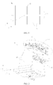
- FIG. 1 is a top view of a battery module according to some embodiments of this application.
- a direction indicated by the arrow X is a first direction
- a direction indicated by the arrow Y is a third direction.
- the first direction X is perpendicular to the third direction Y.
- the battery module 1 includes a submodule 13.
- the submodule 13 includes a plurality of battery cells 131 arranged in sequence along the first direction X.
- the battery module 1 includes one submodule 13.
- the battery module 1 includes a plurality of submodules 13.
- the plurality of submodules 13 are arranged along the third direction Y.
- Each submodule 13 includes a plurality of battery cells 131 arranged in sequence along the first direction X. Illustratively, as shown in FIG. 1 , there are two submodules 13.
- the battery module 1 further includes two end plates 11 and two side plates 12.
- the plurality of submodules 13 are located between the two end plates 11.
- the plurality of submodules 13 are located between the two side plates 12.
- the two end plates 11 are connected to the two side plates 12 and form a rectangular frame structure to fix a plurality of submodules 13.
- a plurality of submodules 13 are integrated in the battery module 1, thereby increasing an energy density of an individual battery module 1.
- the battery module 1 further includes an intermediate partition plate 14.
- the intermediate partition plate 14 is disposed between adjacent submodules 13. Two ends of the intermediate partition plate 14 are connected to the two end plates 11 respectively. A battery cell is prone to expand during use and thereby apply an expansion force to the end plates 11. By disposing the intermediate partition plate 14, this application can increase the overall strength of the battery module 1, and reduce the risk of detaching the end plates 11 from the side plates 12 under the expansion force.
- the inventor of this application fixes one end plate 11 first, and then the fixed end plate 11 is used as a benchmark against which the submodule 13, the side plates 12, and the other end plate 11 are assembled separately.
- the inventor of this application finds that the overall stability of the assembled battery module 1 is inferior due to insufficient positioning precision of the end plate 11 fixed first.
- the length of the end plate 11 in the third direction Y is increased. This makes it more difficult to fix the end plate 11, and affects the positioning precision of the end plate 11.
- no structure for positioning the end plate 11 is disposed in the battery module assembling equipment.
- this application provides an end plate positioning apparatus and battery module assembling equipment to bring the end plate 11 into position during the assembling of the battery module 1, thereby improving the positioning precision during the assembling of the battery module 1.
- An embodiment of this application provides battery module assembling equipment, including an end plate positioning apparatus.
- the end plate positioning apparatus is located on a side of a battery module assembling platform of the battery module assembling equipment along the first direction X.
- one end plate 11 is positioned by the end plate positioning apparatus first, and then this end plate 11 is used as a benchmark against which a plurality of submodules 13, an intermediate partition plate 14, side plates 12, the other end plate 11, and the like are assembled on the battery module assembling platform.
- a desired battery module 1 with a high energy density is obtained.
- the end plate 11 is positioned by the end plate positioning apparatus to ensure that the end plate 11 is positioned at a relatively high precision.
- the end plate positioning apparatus is adaptable to the positioning of end plates 11 of different lengths, so as to meet the requirement of assembling different numbers of submodules 13 into one battery module 1, and increase the energy density of the battery module 1.
- the end plate positioning apparatus is described in detail below using an example of a battery module 1 that contains two submodules 13.
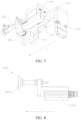
- FIG. 2 is a schematic structural diagram of an end plate positioning apparatus according to some embodiments of this application.
- a direction indicated by the arrow X is a first direction
- a direction indicated by the arrow Y is a third direction
- a direction indicated by the arrow Z is a second direction.
- the first direction X, the second direction Z, and the third direction Y are perpendicular to one other.
- the end plate positioning apparatus 2 includes a pedestal 21 and a supporting piece 23.
- the pedestal 21 is configured to connect the end plate positioning apparatus 2 into the battery module assembling equipment.
- the supporting piece 23 is disposed on the pedestal 21, and the supporting piece 23 is configured to hold the end plate 11.
- the end plate positioning apparatus 2 includes a positioning mechanism 22.
- the positioning mechanism 22 is connected to the pedestal 21.
- the supporting piece 23 includes a supporting platform.
- the supporting platform is kept flush with the battery module assembling platform.
- a robotic arm grabs an end plate 11 and places it on the supporting platform, and then the robotic arm releases the end plate 11.
- the positioning mechanism 22 moves to position the end plate 11 at the same time that the robotic arm places the end plate 11 onto the supporting platform.
- the positioning mechanism 22 disposed can improve the positioning precision of the end plate 11 to ensure a desirable assembling effect of the battery module. After the end plate 11 is brought into position, the position needs to be maintained until completion of assembling one battery module, during which the positioning mechanism 22 needs to be prevented from interfering with other components.
- the specific structure of the positioning mechanism 22 is described in detail below.
- the end plate positioning apparatus includes at least one first positioning mechanism 221.
- the first positioning mechanism 221 is configured to position the end plate 11 in the second direction Z. In the second direction Z, the end plate 11 is confined to a space between the first positioning mechanism 221 and the supporting platform.
- a plurality of first positioning mechanisms 221 are spaced out along the third direction Y, so that the first positioning mechanisms 221 are configured to position the end plates 11 of different lengths in the height direction.
- the plurality of first positioning mechanisms 221 can avoid a problem that the end plate 11 is prone to be offset along the second direction Z due to a considerable length.
- the second direction Z is parallel to the height direction.
- the first positioning mechanisms 221 and the supporting pieces 22 are identical in number and disposed in a one-to-one correspondence.
- the one-to-one correspondence between the first positioning mechanisms 221 and the supporting pieces 23 achieves an effect that the end plate 11 is uniformly stressed everywhere in the length direction in the third direction Y, thereby avoiding deformation caused by a local overstress of the end plate 11, and improving stability of positioning the end plate 11.
- the first positioning mechanism 221 includes a first positioning piece 200 and a positioning locking piece 300, and the first positioning piece 200 is rotatably connected to the pedestal 21.
- the pedestal 21 contains a fixing plate 400.
- the first positioning piece 200 is rotatably connected to the fixing plate 400.
- the positioning locking piece 300 includes a guide portion 310 and a slide portion 320.
- One of the guide portion 310 or the slide portion 320 is disposed on the first positioning piece 200, and the other is disposed on the pedestal 21.
- the guide portion 310 is disposed on the fixing plate 400, and the fixing plate 400 can connect the guide portion 310 to the pedestal 21.
- the guide portion 310 includes a first position 310a and a second position 310b.
- the slide portion 320 can move between the first position 310a and the second position 310b to drive the first positioning piece 200 to rotate.
- the first positioning piece 200 is in abutment with the end plate 11, so that the first positioning piece 200 and the supporting piece clamp the end plate 11 from both sides of the second direction Z.
- the slide portion 320 is located in the second position 310b, the first positioning piece 200 is out of abutment with the end plate 11. In an initial state, the slide portion 320 stays in the second position 310b.
- the positioning locking piece 300 can unlock the first positioning piece 200, so that a relative movement occurs between the guide portion 310 and the slide portion 320.
- the slide portion 320 moves from the first position 310a to the second position 310b, and drives the first positioning piece 200 to move to abut on the surface of the end plate 11 on a side away from the supporting platform, and stay in the abutment state.
- the slide portion 320 is driven to change over between the first position 310a and the second position 310b so that the first positioning piece 200 is driven to rotate until the first positioning piece is in abutment with or out of abutment with the end plate 11 and stays in the corresponding position.
- the first positioning piece 200 brings the end plate 11 into position steadily and precisely, thereby avoiding decrease in the positioning precision of the end plate 11 caused by an impact on the end plate positioning apparatus during the assembling, and in turn, improving the assembling precision of the battery module.
- the first positioning mechanism 221 drives the slide portion 320 to change over between the first position 310a and the second position 310b to drive the first positioning piece 200 to rotate, so as to bring the end plate 11 into position or out of position.
- This arrangement can avoid interference between the end plate 11 and the first positioning mechanism 221 when the robotic arm grabs and moves the end plate 11, so as to facilitate the grab and placement of the end plate 11.
- the design of the first positioning mechanism 221 can convert rotation into a movement in the second direction Z to implement positioning of the end plate 11, without occupying much space in the second direction Z.
- the end plate positioning apparatus achieves the purpose of positioning the end plate 11 in the limited space of the battery module assembling equipment, and implements positioning of the end plate 11 in the height direction by fully utilizing the limited space in the second direction Z, thereby avoiding the problem that the end plate 11 is prone to be out of position in the height direction due to a considerable length of the placed end plate 11, and improving the positioning precision of the end plate 11.
- the first positioning piece 200 includes a connecting rod 210 and a hold-down bar 220.
- One end of the connecting rod 210 is rotatably connected to the pedestal 21, and the other end is connected to the hold-down bar 220.
- a supporting piece is disposed on the sidewall of the pedestal 21 in the first direction X, so that a least a part of the pedestal 21 is higher than the supporting platform.
- the connecting rod 210 is connected to the pedestal 21 at a position higher than the supporting platform. At least the part of the connecting rod 210, at which the hold-down bar 220 is disposed, protrudes out of the pedestal 21 and is located above the supporting platform.
- the connecting rod 210 is rotatably connected to the pedestal 21 through a spindle 500, so that the connecting rod 210 can drive the hold-down bar 220 to rotate relative to the pedestal 21 to approach or move away from the end plate 11.
- the slide portion 320 is connected to the connecting rod 210, the guide portion 310 is movably connected to the pedestal 21, and both are located in a position close to the spindle 500 on the pedestal 21, so that the guide portion 310 can move relative to the pedestal 21 along the first direction X, and drive the slide portion 320, which fits with the guide portion, to change over between the first position 310a and the second position 310b.
- the length direction of the connecting rod 210 is parallel to the first direction X
- the hold-down bar 220 is in abutment with the end plate 11 along the second direction Z
- the first direction X intersects the second direction Z.
- the length direction of the connecting rod 210 is at a preset angle b to the first direction X.
- the length of the hold-down bar 220 needs to be designed beforehand according to the height of the end plate 11 placed on the supporting platform. In this way, when the length direction of the connecting rod 210 is parallel to the first direction X, the length direction of the hold-down bar 220 is parallel to the second direction Z, and the surface of the hold-down bar 220 is in abutment with the end plate 11.
- the preset angle b by which the connecting rod 210 rotates relative to the pedestal 21 is adjustable depending on the actual situation.
- the limited space reserved above allows the connecting rod 210 to rotate upward from the first direction X by an angle falling within a maximum angle range.
- the preset angle b is adaptively adjustable within the allowable maximum angle range depending on actual situations, without being limited herein.
- a central connecting line between the first position 310a and the second position 310b is at an angle to the first direction X when the connecting rod 210 is parallel to the first direction X, and this angle needs to be equal to the preset angle b in order to ensure the positioning precision of the end plate 11 and improve accuracy of control of the preset angle b of rotation of the connecting rod 210.
- the central connecting line between the first position 310a and the second position 310b is parallel to the length direction of the connecting rod 210.
- the end plate 11 can be automatically brought into position and out of position at a relatively high precision, thereby reducing the positioning error caused by repeated changeover.
- the slide portion 320 may be in diversified structural fit with the guide portion 310.
- the guide portion 310 includes a guide slot
- the slide portion 320 includes a bulge extending into the guide slot
- the bulge is slidably connected to the guide slot.
- the bulge is slidably connected into the guide slot, and can move to the first position 310a or second position 310b along a track of the guide slot.
- the simple structural fit facilitates the changeover of the slide portion 320 between the first position 310a and the second position 310b, thereby facilitating assembling.
- the fit between the bulge and the guide slot provides a guiding effect for the rotation of the connecting rod 210 relative to the pedestal 21, thereby ensuring proper positioning of the end plate 11 in the height direction.
- the guide slot includes at least a first hole and a second hole that communicate with each other.
- a connecting line of an axis of the first hole and an axis of the second hole is at a preset angle b to the first direction X.
- the length direction of the connecting rod 210 is parallel to the first direction X when the bulge is located in the first hole, and the length direction of the connecting rod 210 is at the preset angle b to the first direction X when the bulge slides to the second hole.
- the guide slot further includes a communicating channel 310c.
- the communicating channel 310c implements communication between the first hole and the second hole. After being connected to the guide slot, the bulge can change over positions between the first hole and the second hole through the communicating channel 310c.
- the bulge When the bulge is located in the first hole, at least a part of the bulge abuts on the sidewall defined by the first hole.
- the sidewall defined by the first hole restricts the bulge from further moving away from the second hole, so that the hold-down bar 220 keeps in abutment with the end plate 11.
- the bulge needs to be controlled to move to the second hole along the communicating channel 310c until at least a part of the bulge abuts on the sidewall defined by the second hole.
- the sidewall defined by the second hole restricts the bulge from further moving away from the first hole, so that the hold-down bar 220 keeps out of abutment with the end plate 11.
- the preset angle b by which the connecting rod 210 is rotated can be adjusted through the fit between the bulge and the first hole or second hole.
- This adjustment manner can control the connecting rod 210 at a relatively high precision to rotate by an angle that changes over between an initial 0-degree angle and the preset angle b, so as to ensure that the hold-down bar 220 can implement efficient and quick positioning in the height direction on each occasion of positioning the end plate 11.
- the first hole and the second hole may be through-holes or blind holes.
- both holes can be in clearance fit with the bulge.
- this enables the bulge to change over positions between the first hole and the second hole through the communicating channel 310c between the first hole and the second hole.
- the diameter of the bulge is at equal distances to the two sidewalls of the communicating channel 310c, so as to ensure the stability of movement of the bulge in the guide slot and implement self-locking, and in turn, improve the stability of positioning the end plate 11 in the second direction Z.
- first hole and the second hole is not specifically limited herein, for example, whether the holes are through-hole or blind holes, whether the hole wall is smooth or contains fitting bulges and recesses for a purpose of guiding, and whether the shape of the holes is circular or elliptical.
- both the first hole and the second hole are circular through-holes, and the preset angle b is set to one of 15°, 30°, or 45°.
- the two sidewalls of the communicating channel 310c are tangent to the first hole and the second hole respectively.
- the smooth transition connection between the three components facilitates the bulge to change over positions between the first hole and the second hole, and improves the smoothness of the changeover.
- the positioning locking piece 300 in order to enable the slide portion 320 to slide in the guide portion 310 to change over between the first position 310a and the second position 310b, the positioning locking piece 300 further includes a first driving portion 330.
- the first driving portion 330 is connected to the pedestal 21, and is configured to drive the guide portion 310 to move along the first direction X.
- the first driving portion 330 may be a driving cylinder.
- the first driving portion 330 When the slide portion 320 is located in the first position 310a of the guide portion 310, the first hole is located above the second hole, the length direction of the connecting rod 210 is parallel to the first direction X, and the hold-down bar 220 abuts on the end plate 11.
- the first driving portion 330 is driven to move, so that the guide portion 310 is driven to move in the first direction X toward a side away from the second hole.
- the connecting rod 210 rotates by the preset angle b at the same time that the slide portion 320 on the connecting rod 210 moves to the second position 310b along the communicating 310c, thereby making the hold-down bar 220 be out of abutment with the end plate 11.
- the movement in the first direction X is converted into a desired movement in the second direction Z by the fit between the first driving portion 330, the slide portion 320, and the guide portion 310 that are disposed, thereby implementing stable positioning of the end plate 11 at a high precision on the basis of reducing the occupation of space in the second direction Z.
- a guide rail 340 and a slide block 350 that fit with each other are disposed on the guide portion and the pedestal respectively.
- the slide block 350 is connected to a driving plunger rod of the first driving portion 330.
- the slide block 350 is fixedly connected to the guide portion 310 to drive the guide portion 310 to move along the first direction X, thereby driving the slide portion 320 in fit with the guide portion 310 to move along the track of the guide slot in the guide portion 310.
- the fit between the guide rail 340 and the slide block 350 is designed to provide a guiding function for the first driving portion 330 to drive the guide portion 310 to move along the first direction X.
- the end plate positioning apparatus further includes a second positioning mechanism 222.
- the second positioning mechanism 222 is configured to position the end plate in the first direction X.
- the second positioning mechanism 222 includes a suction cup 222a and a second driving portion 222b.
- the suction cup 222a is movably connected to the pedestal.
- the suction cup 222a contains a suction end face configured to attract the end plate.
- the second driving portion 222b is connected to the pedestal, and configured to drive the suction cup 222a to draw the end plate to approach or move away from the pedestal.
- the second positioning mechanism 222 disposed can draw the end plate into position before the robotic arm gives up grabbing the end plate, and prevent the end plate from tipping over before the first positioning mechanism starts to function.
- the second positioning mechanism 222 disposed makes it unnecessary for the robotic arm to place the end plate on the supporting platform in such a position that the hold-down bar can abut on the end plate, thereby reducing the difficulty of placing the end plate by the robotic arm, and preventing the robotic arm or the end plate from colliding with the first positioning mechanism.
- the second driving portion 222b can drive the suction cup 222a to move away from the pedestal and close to the placed end plate along the first direction X. After the suction cup 222a attracts the surface of the end plate to fix the end plate, the second driving portion 222b drives the suction cup 222a to move in an opposite direction, so as to drive the end plate to move toward the pedestal.
- the end plate is finally located on the supporting platform in a position from which the end plate can fit with the first positioning mechanism.
- the suction cup 222a is adaptable to end plates of different dimensions, and helps to position the end plate without impairing the integrity of the end plate.
- the manner in which the second driving portion 222b drives the suction cup 222a to move provides adaptability for the robotic arm to place the end plate in different positions of the supporting platform or the battery module assembling platform, so as to implement positioning of the end plate in the first direction X.
- the robotic arm does not have to place the end plate beforehand in a position reachable to the first positioning mechanism. Instead, the suction cup 222a draws the end plate to move to the corresponding position, thereby avoiding interference with the first positioning mechanism during the placement of the end plate onto the supporting platform, and reducing the difficulty of placing the end plate.
- the pedestal 21 contains a first sidewall 211.
- the first sidewall 211 is located in the first direction X on a side used for holding the end plate.
- the supporting piece 23 is detachably connected to the first sidewall 211.
- An abutting piece 24 is disposed above the supporting piece 23 on the first sidewall 211.
- the end plate 21 is in contact and fit with the abutting piece 24 when the suction cup 222a draws the end plate to approach the pedestal 21.
- the abutting piece 24 contains an abutting face 241.
- the abutting face 241 protrudes out of the first sidewall 211 toward the supporting piece 23 in the first direction X.
- the pedestal 21 contains a recessed position 212.
- At least a part of the second positioning mechanism 222 is located in the recessed position 212.
- the suction cup 222a can penetrate above the supporting platform to attract the end plate located on the battery module assembling platform, and drive the end plate to move in a direction toward the pedestal 21 along the supporting platform until the surface of the end plate fits closely with the abutting face 241.
- the end plate is not only positioned in the first direction X by the second positioning mechanism 222, but also moved to a position from which the first positioning mechanism can implement positioning of the end plate, thereby avoiding the collision caused by direct placement of the end plate onto the supporting platform, and improving the stability and precision of positioning.
- the abutting piece 24 may be a metal part capable of heat dissipation, such as a copper sheet. This provides a high heat dissipation capability during the assembling of the battery module, and avoids safety performance problems of the battery module caused by a heat dissipation failure due to the close fitting between the end plate and the abutting piece 24 during welding.
- the end plate positioning apparatus further includes a third positioning mechanism 223.
- the third positioning mechanism 223 can move relative to the pedestal 21 along the first direction X.
- the third positioning mechanism 223 includes a mounting portion 223a movably connected to the pedestal 21, so that the mounting portion 223a can move along the first direction X.
- the first positioning mechanism 221 and the third positioning mechanism 223 are connected to the battery module assembling equipment separately.
- the first positioning mechanism 221 is fixedly connected, and the third positioning mechanism 223 is slidably connected, to the battery module assembling equipment, so that the third positioning mechanism 223 can move relative to the pedestal 21 along the first direction X.
- a clamping portions 223c are movably connected to the mounting portion 223a.
- the clamping portions 223c are symmetrically arranged along the third direction Y, and are located on two sides of the pedestal 21 in the third direction Y respectively.
- a third driving portion 223b is disposed on the mounting portion 223a.
- the third driving portion 223b is configured to drive the two symmetrically arranged clamping portions 223c to approach each other or move away from each other along the third direction Y, where the third direction Y intersects the first direction X.
- the third positioning mechanism 223 is located on a side of the pedestal 21 away from the supporting platform 231 in the first direction, so as to avoid interference between the third positioning mechanism 223, the first positioning mechanism 221, and the end plate.
- the end plate After the end plate is positioned by the first positioning mechanism 221 and the second positioning mechanism, the end plate abuts on the abutting piece 24.
- the mounting portion 223a drives the clamping portions 223c to move along the first direction X to a position corresponding to the end plate. In this way, the two clamping portions 223c are located on the same straight line in the third direction Z and the length direction of the end plate 11, and the two clamping portions 223c are located on two opposite sides of the end plate 11.
- the third driving portion 223b controls the two clamping portions 223c to approach each other. In this way, the clamping faces of the clamping portions 223c abut on the surface of the end plate to implement clamping and positioning of the end plate in the third direction Z, thereby further improving the positioning precision of the end plate.
- the mounting portion 223a possesses an alignment center line 223d.
- the alignment center line 223d is located in a middle position between the two clamping portions 223c along the third direction Y. With the alignment center line 223d disposed, during arrangement of the third positioning mechanism 223, the alignment center line 223d is controlled to be aligned with a preset end plate position center line on the pedestal 21 first.
- the alignment center line 223d can be located at the center of the end plate 11 in the third direction Y, thereby ensuring a high precision of the position of the end plate on the supporting platform 231 and facilitating subsequent assembling and formation of the battery module.
Landscapes
- Chemical & Material Sciences (AREA)
- Chemical Kinetics & Catalysis (AREA)
- Electrochemistry (AREA)
- General Chemical & Material Sciences (AREA)
- Engineering & Computer Science (AREA)
- Manufacturing & Machinery (AREA)
- Battery Mounting, Suspending (AREA)
Abstract
Description
- This application claims priority to
Chinese Patent Application No. 202120963358.X, filed on May 7, 2021 - This application relates to the technical field of batteries, and in particular, to an end plate positioning apparatus and battery module assembling equipment.
- Battery cells are widely used in electronic devices such as a mobile phone, a notebook computer, an electric power cart, an electric vehicle, an electric airplane, an electric ship, an electric toy car, an electric toy ship, an electric toy airplane, and a power tool. The battery cells may include a nickel-cadmium battery cell, a nickel-hydrogen battery cell, a lithium-ion battery cell, a secondary alkaline zinc-manganese battery cell, and the like.
- When a plurality of battery cells are used in groups, the plurality of battery cells are assembled together to form a battery module. How to improve the assembling process of battery modules has always been a research topic in the industry.
- This application provides an end plate positioning apparatus and battery module assembling equipment to improve precision of assembling battery modules.
- According to one aspect, an embodiment of this application provides an end plate positioning apparatus, applicable to assembling of battery modules. The end plate positioning apparatus includes: a pedestal; a supporting piece, disposed on the pedestal and configured to hold an end plate; at least one first positioning mechanism, including a first positioning piece and a positioning locking piece, where the first positioning piece is rotatably connected to the pedestal, the positioning locking piece includes a guide portion and a slide portion, one of the guide portion or the slide portion is disposed on the first positioning piece, and the other is disposed on the pedestal; the guide portion includes a first position and a second position, and the slide portion is able to move between the first position and the second position to drive the first positioning piece to rotate; when the slide portion is located in the first position, the first positioning piece is in abutment with the end plate, so that the first positioning piece and the supporting piece clamp the end plate from both sides; and, when the slide portion is located in the second position, the first positioning piece is out of abutment with the end plate.
- In the foregoing solution, the design of the first positioning mechanism can convert rotation into a movement in the third direction to implement positioning of the end plate, without occupying much space in the vertical third direction. In this way, the end plate positioning apparatus achieves the purpose of positioning the end plate in the limited space of the battery module assembling equipment, and implements positioning of the end plate in a height direction by fully utilizing the limited space in the vertical third direction, thereby avoiding the problem that the end plate is prone to be out of position in the height direction due to a considerable length of the placed end plate, and improving the positioning precision of the end plate.
- According to an aspect of embodiments of this application, the first positioning piece includes a connecting rod and a hold-down bar. One end of the connecting rod is rotatably connected to the pedestal, and the other end is connected to the hold-down bar. The slide portion is connected to the connecting rod. The guide portion is movably connected to the pedestal. The guide portion is able to move relative to the pedestal along a first direction so that, when the slide portion is located in the first position, a length direction of the connecting rod is parallel to the first direction, the hold-down bar is in abutment with the end plate along a second direction, and the first direction intersects the second direction, and so that, when the slide portion is located in the second position, the length direction of the connecting rod is at a preset angle to the first direction.
- In the foregoing solution, as long as the slide portion is controlled to change over between the first position and the second position, the end plate can be automatically brought into position and out of position at a relatively high precision, thereby reducing the positioning error caused by repeated changeover.
- According to an aspect of this application, the guide portion includes a guide slot. The slide portion includes a bulge extending into the guide slot. The bulge is slidably connected to the guide slot.
- In the foregoing solution, a simple structural fit facilitates the changeover of the slide portion between the first position and the second position, thereby facilitating assembling. In addition, the fit between the bulge and the guide slot provides a guiding effect for the rotation of the connecting rod relative to the pedestal, thereby ensuring proper positioning of the end plate in the height direction.
- According to an aspect of embodiments of this application, the guide slot includes at least a first hole and a second hole that communicate with each other. A connecting line of an axis of the first hole and an axis of the second hole is at a preset angle to the first direction. The length direction of the connecting rod is parallel to the first direction when the bulge is located in the first hole, and the length direction of the connecting rod is at the preset angle to the first direction when the bulge slides to the second hole.
- In the foregoing solution, the preset angle by which the connecting rod is rotated can be adjusted through the fit between the bulge and the first hole or second hole, and the connecting rod can be controlled at a relatively high precision to rotate by an angle that changes over between an initial 0-degree angle and the preset angle, so as to ensure that the hold-down bar can implement efficient and quick positioning in the height direction on each occasion of positioning the end plate.
- According to an aspect of embodiments of this application, the first hole and the second hole are through-holes, or, the first hole and the second hole are blind holes.
- In the foregoing solution, the stability of the movement of the bulge in the guide slot is ensured, thereby improving the stability of positioning the end plate in the third direction.
- According to an aspect of embodiments of this application, the positioning locking piece further includes a first driving portion. The first driving portion is connected to the pedestal and is configured to drive the guide portion to move along the first direction.
- In the foregoing solution, the movement in the first direction is converted into a desired movement in the second direction by the fit between the first driving portion, the slide portion, and the guide portion that are disposed, thereby implementing stable positioning of the end plate at a high precision on the basis of reducing the occupation of space in the second direction.
- According to an aspect of embodiments of this application, the end plate positioning apparatus further includes a second positioning mechanism. The second positioning mechanism includes: a suction cup, movably connected to a side of the pedestal toward the end plate, where the suction cup contains an suction end face configured to attract the end plate; and a second driving portion, connected to the pedestal, and configured to drive the suction cup to draw the end plate to approach or move away from the pedestal.
- In the foregoing solution, the second positioning mechanism disposed can draw the end plate into position before an robotic arm gives up grabbing the end plate, and prevent the end plate from tipping over before the first positioning mechanism starts to function.
- According to an aspect of embodiments of this application, the pedestal contains a first sidewall. The supporting piece is detachably connected to the first sidewall. An abutting piece is disposed above the supporting piece on the first sidewall. The end plate is in contact and fit with the abutting piece when the suction cup draws the end plate to approach the pedestal.
- In the foregoing solution, the end plate is not only positioned in the first direction by the second positioning mechanism, but also moved to a position from which the second positioning mechanism can implement positioning of the end plate, thereby avoiding the collision caused by direct placement of the end plate into this position, and improving the stability and precision of positioning.
- According to an aspect of embodiments of this application, the end plate positioning apparatus further includes a third positioning mechanism. The third positioning mechanism is able to move relative to the pedestal along the first direction. The third positioning mechanism includes: a mounting portion, movably connected to the pedestal so that the mounting portion is able to move along the first direction; clamping portions, movably connected to the mounting portion, and symmetrically arranged along a third direction; and a third driving portion, connected to the mounting portion, and configured to drive the symmetrically arranged clamping portions to approach each other or move away from each other along the third direction. The third direction intersects the first direction.
- In the foregoing solution, the third positioning mechanism implements the positioning and clamping of the end plate in the third direction to improve the positioning precision, without causing movement interference between the third positioning mechanism and the first positioning mechanism, the end plate, and the like.
- According to an aspect of embodiments of this application, the mounting portion possesses an alignment center line. The alignment center line is located in a middle position between the two clamping portions along the third direction.
- In the foregoing solution, the precision of placing the end plate on a mounting platform is ensured, thereby facilitating subsequent assembling of battery modules.
- According to another aspect, an embodiment of this application further discloses battery module assembling equipment. The battery module assembling equipment includes the end plate positioning apparatus according to any embodiment of the first aspect described above.
- To describe the technical solutions in the embodiments of this application more clearly, the following outlines the drawings used in the embodiments of this application. Evidently, the drawings outlined below are merely a part of embodiments of this application. A person of ordinary skill in the art may derive other drawings from the outlined drawings without making any creative efforts.
-
FIG. 1 is a top view of a battery module according to some embodiments of this application; -
FIG. 2 is a schematic structural diagram of an end plate positioning apparatus according to some embodiments of this application; -
FIG. 3 is a close-up view of a part A shown inFIG. 2 ; -
FIG. 4 is a front view of an end plate positioning apparatus in which a first positioning mechanism is located in a first position according to some embodiments of this application; -
FIG. 5 is a front view of an end plate positioning apparatus in which a first positioning mechanism is located in a second position according to some embodiments of this application; -
FIG. 6 is a schematic structural diagram of an end plate positioning apparatus when a first positioning mechanism brings an end plate into position according to some embodiments of this application; -
FIG. 7 is an overall schematic structural diagram of a first positioning mechanism in an end plate positioning apparatus according to some embodiments of this application; -
FIG. 8 is a schematic structural diagram of a second positioning mechanism in an end plate positioning apparatus according to some embodiments of this application; -
FIG. 9 is a schematic structural diagram of a pedestal in an end plate positioning apparatus according to some embodiments of this application; -
FIG. 10 is a schematic structural diagram of another end plate positioning apparatus according to some embodiments of this application; and -
FIG. 11 is a schematic structural diagram of a third positioning mechanism in an end plate positioning apparatus according to some embodiments of this application. - The drawings are not drawn to scale.
- To make the objectives, technical solutions, and advantages of the embodiments of this application clearer, the following gives a clear description of the technical solutions in the embodiments of this application with reference to the drawings in the embodiments of this application. Evidently, the described embodiments are merely a part of but not all of the embodiments of this application. All other embodiments derived by a person of ordinary skill in the art based on the embodiments of this application without making any creative efforts fall within the protection scope of this application.
- Unless otherwise defined, all technical and scientific terms used herein have the same meanings as usually understood by a person skilled in the technical field of this application. The terms used in the specification of this application are merely intended for describing specific embodiments but are not intended to limit this application. The terms "include" and "contain" and any variations thereof used in the specification, claims, and brief description of drawings of this application are intended as non-exclusive inclusion. The terms such as "first" and "second" used in the specification, claims, and brief description of drawings herein are intended to distinguish between different items, but are not intended to describe a specific sequence or order of precedence.
- Reference to "embodiment" in this application means that a specific feature, structure or characteristic described with reference to the embodiment may be included in at least one embodiment of this application. Reference to this term in different places in the specification does not necessarily represent the same embodiment, nor does it represent an independent or alternative embodiment in a mutually exclusive relationship with other embodiments. A person skilled in the art explicitly and implicitly understands that the embodiments described in this application may be combined with other embodiments.
- In the description of this application, unless otherwise expressly specified and defined, the terms "mount", "concatenate", "connect", and "attach" are understood in a broad sense. For example, a "connection" may be a fixed connection, a detachable connection, or an integrated connection; or may be a direct connection or an indirect connection implemented through an intermediary; or may be internal communication between two components. A person of ordinary skill in the art understands the specific meanings of the terms in this application according to the context.
- The term "and/or" in this application indicates merely a relation for describing the related items, and represents three possible relationships. For example, "A and/or B" may represent the following three circumstances: A alone, both A and B, and B alone. In addition, the character "/" herein generally indicates an "or" relationship between the item preceding the character and the item following the character.
- "A plurality of" referred to in this application means two or more (including two). Similarly, "a plurality of groups" means two or more groups (including two groups).
- In this application, the term "parallel" includes not only absolute parallelism, but also approximate parallelism conventionally known in engineering. Similarly, the term "perpendicular" or "vertical" includes not only absolute perpendicularity, but also approximate perpendicularity conventionally known in engineering.
- Due to advantages such as a high energy density, a high power density, reusability for many cycles, and a long storage time, battery cells such as a lithium-ion secondary battery cell, a lithium-sulfur battery cell, a sodium-lithium-ion battery cell, a sodium-ion battery cell, or a magnesium-ion battery cell have been widely used in electrical devices in which the battery cells are applicable. For example, the electrical device may be a mobile phone, a portable device, a notebook computer, an electric power cart, an electric vehicle, a ship, a spacecraft, an electric toy, an electric tool, or the like. For example, the spacecraft includes an airplane, a rocket, a space shuttle, a spaceship, and the like. The electric toy includes a fixed or mobile electric toy, such as a game console, an electric car toy, an electric ship toy, an electric airplane toy, and the like. The electric tool includes an electric tool for metal cutting, an electric grinding tool, an electric assembly tool, an electric tool for railways, such as an electric drill, an electric grinder, an electric wrench, an electric screwdriver, an electric hammer, an electric impact drill, a concrete vibrator, and an electric planer.
- Understandably, the technical solutions described in embodiments of this application are not only applicable to the devices described above, but also applicable to all devices that use a battery.
- To meet different power usage requirements, a plurality of battery cells may be connected in series, parallel, or series-and-parallel pattern to form a battery module, and then a plurality of battery modules may be connected in series, parallel, or series-and-parallel pattern to form a battery. The battery may also be referred to as a battery pack.
-
FIG. 1 is a top view of a battery module according to some embodiments of this application. As shown inFIG. 1 , a direction indicated by the arrow X is a first direction, and a direction indicated by the arrow Y is a third direction. Illustratively, the first direction X is perpendicular to the third direction Y. - In some embodiments, the battery module 1 includes a
submodule 13. Thesubmodule 13 includes a plurality ofbattery cells 131 arranged in sequence along the first direction X. In some embodiments, the battery module 1 includes onesubmodule 13. In other embodiments, the battery module 1 includes a plurality ofsubmodules 13. The plurality ofsubmodules 13 are arranged along the third direction Y. Eachsubmodule 13 includes a plurality ofbattery cells 131 arranged in sequence along the first direction X. Illustratively, as shown inFIG. 1 , there are two submodules 13. - In some embodiments, the battery module 1 further includes two
end plates 11 and twoside plates 12. In the first direction X, the plurality ofsubmodules 13 are located between the twoend plates 11. In the third direction Y, the plurality ofsubmodules 13 are located between the twoside plates 12. Illustratively, the twoend plates 11 are connected to the twoside plates 12 and form a rectangular frame structure to fix a plurality ofsubmodules 13. In embodiments of this application, a plurality ofsubmodules 13 are integrated in the battery module 1, thereby increasing an energy density of an individual battery module 1. - In some embodiments, the battery module 1 further includes an
intermediate partition plate 14. Theintermediate partition plate 14 is disposed betweenadjacent submodules 13. Two ends of theintermediate partition plate 14 are connected to the twoend plates 11 respectively. A battery cell is prone to expand during use and thereby apply an expansion force to theend plates 11. By disposing theintermediate partition plate 14, this application can increase the overall strength of the battery module 1, and reduce the risk of detaching theend plates 11 from theside plates 12 under the expansion force. - During assembling of the battery module 1, the inventor of this application fixes one
end plate 11 first, and then thefixed end plate 11 is used as a benchmark against which thesubmodule 13, theside plates 12, and theother end plate 11 are assembled separately. However, the inventor of this application finds that the overall stability of the assembled battery module 1 is inferior due to insufficient positioning precision of theend plate 11 fixed first. Especially, when two or more submodules 13 are assembled to form one battery module 1 to increase the energy density of the battery module 1, the length of theend plate 11 in the third direction Y is increased. This makes it more difficult to fix theend plate 11, and affects the positioning precision of theend plate 11. In the related art known to the inventor of this application, no structure for positioning theend plate 11 is disposed in the battery module assembling equipment. - In view of this, this application provides an end plate positioning apparatus and battery module assembling equipment to bring the
end plate 11 into position during the assembling of the battery module 1, thereby improving the positioning precision during the assembling of the battery module 1. - An embodiment of this application provides battery module assembling equipment, including an end plate positioning apparatus. The end plate positioning apparatus is located on a side of a battery module assembling platform of the battery module assembling equipment along the first direction X. During the assembling the battery module 1, one
end plate 11 is positioned by the end plate positioning apparatus first, and then thisend plate 11 is used as a benchmark against which a plurality ofsubmodules 13, anintermediate partition plate 14,side plates 12, theother end plate 11, and the like are assembled on the battery module assembling platform. After the step of fixing by welding, a desired battery module 1 with a high energy density is obtained. - During the assembling of the battery module 1, the
end plate 11 is positioned by the end plate positioning apparatus to ensure that theend plate 11 is positioned at a relatively high precision. The end plate positioning apparatus is adaptable to the positioning ofend plates 11 of different lengths, so as to meet the requirement of assembling different numbers ofsubmodules 13 into one battery module 1, and increase the energy density of the battery module 1. The end plate positioning apparatus is described in detail below using an example of a battery module 1 that contains twosubmodules 13. -
FIG. 2 is a schematic structural diagram of an end plate positioning apparatus according to some embodiments of this application. As shown inFIG. 2 , a direction indicated by the arrow X is a first direction, a direction indicated by the arrow Y is a third direction, and a direction indicated by the arrow Z is a second direction. Illustratively, the first direction X, the second direction Z, and the third direction Y are perpendicular to one other. - An embodiment of this application provides an end plate positioning apparatus. The end plate positioning apparatus 2 includes a
pedestal 21 and a supportingpiece 23. Thepedestal 21 is configured to connect the end plate positioning apparatus 2 into the battery module assembling equipment. The supportingpiece 23 is disposed on thepedestal 21, and the supportingpiece 23 is configured to hold theend plate 11. The end plate positioning apparatus 2 includes apositioning mechanism 22. Thepositioning mechanism 22 is connected to thepedestal 21. - The supporting
piece 23 includes a supporting platform. The supporting platform is kept flush with the battery module assembling platform. During the assembling, a robotic arm grabs anend plate 11 and places it on the supporting platform, and then the robotic arm releases theend plate 11. To ensure the precision and stability of the position of theend plate 11 on the supporting platform, and make theend plate 11 competent as a benchmark against which the battery module is assembled. Thepositioning mechanism 22 moves to position theend plate 11 at the same time that the robotic arm places theend plate 11 onto the supporting platform. Thepositioning mechanism 22 disposed can improve the positioning precision of theend plate 11 to ensure a desirable assembling effect of the battery module. After theend plate 11 is brought into position, the position needs to be maintained until completion of assembling one battery module, during which thepositioning mechanism 22 needs to be prevented from interfering with other components. The specific structure of thepositioning mechanism 22 is described in detail below. - In some specific embodiments, as shown in
FIG. 3 , the end plate positioning apparatus includes at least onefirst positioning mechanism 221. Thefirst positioning mechanism 221 is configured to position theend plate 11 in the second direction Z. In the second direction Z, theend plate 11 is confined to a space between thefirst positioning mechanism 221 and the supporting platform. - In some embodiments, a plurality of
first positioning mechanisms 221 are spaced out along the third direction Y, so that thefirst positioning mechanisms 221 are configured to position theend plates 11 of different lengths in the height direction. The plurality offirst positioning mechanisms 221 can avoid a problem that theend plate 11 is prone to be offset along the second direction Z due to a considerable length. Illustratively, there are twofirst positioning mechanisms 221, and the spacing between the twofirst positioning mechanisms 221 spaced apart is adjustable depending on the specific length of the partition plate, without being specifically limited herein. In some embodiments, the second direction Z is parallel to the height direction. - In some embodiments, the
first positioning mechanisms 221 and the supportingpieces 22 are identical in number and disposed in a one-to-one correspondence. When theend plate 11 is positioned between thefirst positioning mechanisms 221 and the supportingpieces 23 along the second direction Z, the one-to-one correspondence between thefirst positioning mechanisms 221 and the supportingpieces 23 achieves an effect that theend plate 11 is uniformly stressed everywhere in the length direction in the third direction Y, thereby avoiding deformation caused by a local overstress of theend plate 11, and improving stability of positioning theend plate 11. - As shown in
FIG. 4 ,FIG. 5, and FIG. 6 , thefirst positioning mechanism 221 includes a first positioning piece 200 and apositioning locking piece 300, and the first positioning piece 200 is rotatably connected to thepedestal 21. Illustratively, thepedestal 21 contains a fixingplate 400. The first positioning piece 200 is rotatably connected to the fixingplate 400. - The
positioning locking piece 300 includes aguide portion 310 and aslide portion 320. One of theguide portion 310 or theslide portion 320 is disposed on the first positioning piece 200, and the other is disposed on thepedestal 21. In some examples, theguide portion 310 is disposed on the fixingplate 400, and the fixingplate 400 can connect theguide portion 310 to thepedestal 21. - The
guide portion 310 includes afirst position 310a and asecond position 310b. Theslide portion 320 can move between thefirst position 310a and thesecond position 310b to drive the first positioning piece 200 to rotate. When theslide portion 320 is located in thefirst position 310a, the first positioning piece 200 is in abutment with theend plate 11, so that the first positioning piece 200 and the supporting piece clamp theend plate 11 from both sides of the second direction Z. When theslide portion 320 is located in thesecond position 310b, the first positioning piece 200 is out of abutment with theend plate 11. In an initial state, theslide portion 320 stays in thesecond position 310b. After theend plate 11 is grabbed and placed onto the supporting platform by the robotic arm, thepositioning locking piece 300 can unlock the first positioning piece 200, so that a relative movement occurs between theguide portion 310 and theslide portion 320. Theslide portion 320 moves from thefirst position 310a to thesecond position 310b, and drives the first positioning piece 200 to move to abut on the surface of theend plate 11 on a side away from the supporting platform, and stay in the abutment state. In the foregoing arrangement, theslide portion 320 is driven to change over between thefirst position 310a and thesecond position 310b so that the first positioning piece 200 is driven to rotate until the first positioning piece is in abutment with or out of abutment with theend plate 11 and stays in the corresponding position. By virtue of such arrangement, after theend plate 11 is placed onto the supporting platform, the first positioning piece 200 brings theend plate 11 into position steadily and precisely, thereby avoiding decrease in the positioning precision of theend plate 11 caused by an impact on the end plate positioning apparatus during the assembling, and in turn, improving the assembling precision of the battery module. - In addition, during positioning of the
end plate 11, thefirst positioning mechanism 221 drives theslide portion 320 to change over between thefirst position 310a and thesecond position 310b to drive the first positioning piece 200 to rotate, so as to bring theend plate 11 into position or out of position. This arrangement, on the one hand, can avoid interference between theend plate 11 and thefirst positioning mechanism 221 when the robotic arm grabs and moves theend plate 11, so as to facilitate the grab and placement of theend plate 11. On the other hand, the design of thefirst positioning mechanism 221 can convert rotation into a movement in the second direction Z to implement positioning of theend plate 11, without occupying much space in the second direction Z. In this way, the end plate positioning apparatus achieves the purpose of positioning theend plate 11 in the limited space of the battery module assembling equipment, and implements positioning of theend plate 11 in the height direction by fully utilizing the limited space in the second direction Z, thereby avoiding the problem that theend plate 11 is prone to be out of position in the height direction due to a considerable length of the placedend plate 11, and improving the positioning precision of theend plate 11. - In some specific embodiments, the first positioning piece 200 includes a connecting
rod 210 and a hold-downbar 220. One end of the connectingrod 210 is rotatably connected to thepedestal 21, and the other end is connected to the hold-downbar 220. A supporting piece is disposed on the sidewall of thepedestal 21 in the first direction X, so that a least a part of thepedestal 21 is higher than the supporting platform. The connectingrod 210 is connected to thepedestal 21 at a position higher than the supporting platform. At least the part of the connectingrod 210, at which the hold-downbar 220 is disposed, protrudes out of thepedestal 21 and is located above the supporting platform. In some examples, the connectingrod 210 is rotatably connected to thepedestal 21 through aspindle 500, so that the connectingrod 210 can drive the hold-downbar 220 to rotate relative to thepedestal 21 to approach or move away from theend plate 11. Theslide portion 320 is connected to the connectingrod 210, theguide portion 310 is movably connected to thepedestal 21, and both are located in a position close to thespindle 500 on thepedestal 21, so that theguide portion 310 can move relative to thepedestal 21 along the first direction X, and drive theslide portion 320, which fits with the guide portion, to change over between thefirst position 310a and thesecond position 310b. When theslide portion 320 is located in thefirst position 310a, the length direction of the connectingrod 210 is parallel to the first direction X, the hold-downbar 220 is in abutment with theend plate 11 along the second direction Z, and the first direction X intersects the second direction Z. When theslide portion 320 is located in thesecond position 310b, the length direction of the connectingrod 210 is at a preset angle b to the first direction X. - It is hereby noted that, when the
end plate 11 is positioned by controlling the rotation of the connectingrod 210 through the fit between theslide portion 320 and theguide portion 310, the length of the hold-downbar 220 needs to be designed beforehand according to the height of theend plate 11 placed on the supporting platform. In this way, when the length direction of the connectingrod 210 is parallel to the first direction X, the length direction of the hold-downbar 220 is parallel to the second direction Z, and the surface of the hold-downbar 220 is in abutment with theend plate 11. When theend plate 11 needs to be placed on the supporting platform, the preset angle b by which the connectingrod 210 rotates relative to thepedestal 21 is adjustable depending on the actual situation. To be specific, after theend plate 11 is placed on the supporting platform, the limited space reserved above allows the connectingrod 210 to rotate upward from the first direction X by an angle falling within a maximum angle range. The preset angle b is adaptively adjustable within the allowable maximum angle range depending on actual situations, without being limited herein. - In a case that the preset angle b of rotation of the connecting
rod 210 is adjusted by controlling the changeover of theslide portion 320 between thefirst position 310a and thesecond position 310b, a central connecting line between thefirst position 310a and thesecond position 310b is at an angle to the first direction X when the connectingrod 210 is parallel to the first direction X, and this angle needs to be equal to the preset angle b in order to ensure the positioning precision of theend plate 11 and improve accuracy of control of the preset angle b of rotation of the connectingrod 210. When theslide portion 320 moves from thefirst position 310a to thesecond position 310b, the central connecting line between thefirst position 310a and thesecond position 310b is parallel to the length direction of the connectingrod 210. In this case, as long as theslide portion 320 is controlled to change over between thefirst position 310a and thesecond position 310b, theend plate 11 can be automatically brought into position and out of position at a relatively high precision, thereby reducing the positioning error caused by repeated changeover. - Optionally, the
slide portion 320 may be in diversified structural fit with theguide portion 310. For example, theguide portion 310 includes a guide slot, theslide portion 320 includes a bulge extending into the guide slot, and the bulge is slidably connected to the guide slot. With the bulge and the guide slot so disposed, the bulge is slidably connected into the guide slot, and can move to thefirst position 310a orsecond position 310b along a track of the guide slot. The simple structural fit facilitates the changeover of theslide portion 320 between thefirst position 310a and thesecond position 310b, thereby facilitating assembling. In addition, the fit between the bulge and the guide slot provides a guiding effect for the rotation of the connectingrod 210 relative to thepedestal 21, thereby ensuring proper positioning of theend plate 11 in the height direction. - Illustratively, the guide slot includes at least a first hole and a second hole that communicate with each other. A connecting line of an axis of the first hole and an axis of the second hole is at a preset angle b to the first direction X. The length direction of the connecting
rod 210 is parallel to the first direction X when the bulge is located in the first hole, and the length direction of the connectingrod 210 is at the preset angle b to the first direction X when the bulge slides to the second hole. The guide slot further includes a communicatingchannel 310c. The communicatingchannel 310c implements communication between the first hole and the second hole. After being connected to the guide slot, the bulge can change over positions between the first hole and the second hole through the communicatingchannel 310c. When the bulge is located in the first hole, at least a part of the bulge abuts on the sidewall defined by the first hole. The sidewall defined by the first hole restricts the bulge from further moving away from the second hole, so that the hold-downbar 220 keeps in abutment with theend plate 11. When the positioning is completed or when theend plate 11 is initially positioned, the bulge needs to be controlled to move to the second hole along the communicatingchannel 310c until at least a part of the bulge abuts on the sidewall defined by the second hole. The sidewall defined by the second hole restricts the bulge from further moving away from the first hole, so that the hold-downbar 220 keeps out of abutment with theend plate 11. This also avoids collision between theend plate 11 and the hold-downbar 220 during the movement, and avoids mutual interference. In this way, the preset angle b by which the connectingrod 210 is rotated can be adjusted through the fit between the bulge and the first hole or second hole. This adjustment manner can control the connectingrod 210 at a relatively high precision to rotate by an angle that changes over between an initial 0-degree angle and the preset angle b, so as to ensure that the hold-downbar 220 can implement efficient and quick positioning in the height direction on each occasion of positioning theend plate 11. - Understandably, among the first hole and the second hole that communicate with each other, the first hole and the second hole may be through-holes or blind holes. In this way, both holes can be in clearance fit with the bulge. In addition, this enables the bulge to change over positions between the first hole and the second hole through the communicating
channel 310c between the first hole and the second hole. The diameter of the bulge is at equal distances to the two sidewalls of the communicatingchannel 310c, so as to ensure the stability of movement of the bulge in the guide slot and implement self-locking, and in turn, improve the stability of positioning theend plate 11 in the second direction Z. The specific form of the first hole and the second hole is not specifically limited herein, for example, whether the holes are through-hole or blind holes, whether the hole wall is smooth or contains fitting bulges and recesses for a purpose of guiding, and whether the shape of the holes is circular or elliptical. - Illustratively, both the first hole and the second hole are circular through-holes, and the preset angle b is set to one of 15°, 30°, or 45°. In this case, the two sidewalls of the communicating
channel 310c are tangent to the first hole and the second hole respectively. The smooth transition connection between the three components facilitates the bulge to change over positions between the first hole and the second hole, and improves the smoothness of the changeover. - In some embodiments, in order to enable the
slide portion 320 to slide in theguide portion 310 to change over between thefirst position 310a and thesecond position 310b, thepositioning locking piece 300 further includes afirst driving portion 330. Thefirst driving portion 330 is connected to thepedestal 21, and is configured to drive theguide portion 310 to move along the first direction X. - Illustratively, the
first driving portion 330 may be a driving cylinder. When theslide portion 320 is located in thefirst position 310a of theguide portion 310, the first hole is located above the second hole, the length direction of the connectingrod 210 is parallel to the first direction X, and the hold-downbar 220 abuts on theend plate 11. When the hold-downbar 220 needs to be out of abutment with theend plate 11, thefirst driving portion 330 is driven to move, so that theguide portion 310 is driven to move in the first direction X toward a side away from the second hole. In this way, the connectingrod 210 rotates by the preset angle b at the same time that theslide portion 320 on the connectingrod 210 moves to thesecond position 310b along the communicating 310c, thereby making the hold-downbar 220 be out of abutment with theend plate 11. The movement in the first direction X is converted into a desired movement in the second direction Z by the fit between thefirst driving portion 330, theslide portion 320, and theguide portion 310 that are disposed, thereby implementing stable positioning of theend plate 11 at a high precision on the basis of reducing the occupation of space in the second direction Z. - Optionally, as shown in
FIG. 7 , in order to ensure a relatively high precision for thefirst driving portion 330 to drive the guide portion to move along the first direction, aguide rail 340 and aslide block 350 that fit with each other are disposed on the guide portion and the pedestal respectively. Theslide block 350 is connected to a driving plunger rod of thefirst driving portion 330. Theslide block 350 is fixedly connected to theguide portion 310 to drive theguide portion 310 to move along the first direction X, thereby driving theslide portion 320 in fit with theguide portion 310 to move along the track of the guide slot in theguide portion 310. The fit between theguide rail 340 and theslide block 350 is designed to provide a guiding function for thefirst driving portion 330 to drive theguide portion 310 to move along the first direction X. - In some specific embodiments, as shown in
FIG. 8 , the end plate positioning apparatus further includes asecond positioning mechanism 222. Thesecond positioning mechanism 222 is configured to position the end plate in the first direction X. Thesecond positioning mechanism 222 includes asuction cup 222a and asecond driving portion 222b. Thesuction cup 222a is movably connected to the pedestal. Thesuction cup 222a contains a suction end face configured to attract the end plate. Thesecond driving portion 222b is connected to the pedestal, and configured to drive thesuction cup 222a to draw the end plate to approach or move away from the pedestal. During placement of the end plate on the supporting platform, thesecond positioning mechanism 222 disposed can draw the end plate into position before the robotic arm gives up grabbing the end plate, and prevent the end plate from tipping over before the first positioning mechanism starts to function. - In addition, the
second positioning mechanism 222 disposed makes it unnecessary for the robotic arm to place the end plate on the supporting platform in such a position that the hold-down bar can abut on the end plate, thereby reducing the difficulty of placing the end plate by the robotic arm, and preventing the robotic arm or the end plate from colliding with the first positioning mechanism. When the robotic arm places the end plate onto the battery module assembling platform, thesecond driving portion 222b can drive thesuction cup 222a to move away from the pedestal and close to the placed end plate along the first direction X. After thesuction cup 222a attracts the surface of the end plate to fix the end plate, thesecond driving portion 222b drives thesuction cup 222a to move in an opposite direction, so as to drive the end plate to move toward the pedestal. In this way, the end plate is finally located on the supporting platform in a position from which the end plate can fit with the first positioning mechanism. On the one hand, by attracting the end plate, thesuction cup 222a is adaptable to end plates of different dimensions, and helps to position the end plate without impairing the integrity of the end plate. On the other hand, the manner in which thesecond driving portion 222b drives thesuction cup 222a to move provides adaptability for the robotic arm to place the end plate in different positions of the supporting platform or the battery module assembling platform, so as to implement positioning of the end plate in the first direction X. In addition, with thesuction cup 222a being movable, the robotic arm does not have to place the end plate beforehand in a position reachable to the first positioning mechanism. Instead, thesuction cup 222a draws the end plate to move to the corresponding position, thereby avoiding interference with the first positioning mechanism during the placement of the end plate onto the supporting platform, and reducing the difficulty of placing the end plate. - Illustratively, as shown in
FIG. 8 andFIG. 9 , thepedestal 21 contains afirst sidewall 211. Thefirst sidewall 211 is located in the first direction X on a side used for holding the end plate. The supportingpiece 23 is detachably connected to thefirst sidewall 211. An abuttingpiece 24 is disposed above the supportingpiece 23 on thefirst sidewall 211. Theend plate 21 is in contact and fit with the abuttingpiece 24 when thesuction cup 222a draws the end plate to approach thepedestal 21. Specifically, the abuttingpiece 24 contains anabutting face 241. The abuttingface 241 protrudes out of thefirst sidewall 211 toward the supportingpiece 23 in the first direction X. Thepedestal 21 contains a recessedposition 212. At least a part of thesecond positioning mechanism 222 is located in the recessedposition 212. In this way, during positioning of the end plate, thesuction cup 222a can penetrate above the supporting platform to attract the end plate located on the battery module assembling platform, and drive the end plate to move in a direction toward thepedestal 21 along the supporting platform until the surface of the end plate fits closely with theabutting face 241. At this time, the end plate is not only positioned in the first direction X by thesecond positioning mechanism 222, but also moved to a position from which the first positioning mechanism can implement positioning of the end plate, thereby avoiding the collision caused by direct placement of the end plate onto the supporting platform, and improving the stability and precision of positioning. - Optionally, the abutting
piece 24 may be a metal part capable of heat dissipation, such as a copper sheet. This provides a high heat dissipation capability during the assembling of the battery module, and avoids safety performance problems of the battery module caused by a heat dissipation failure due to the close fitting between the end plate and the abuttingpiece 24 during welding. - In some specific embodiments, as shown in
FIG. 10 and FIG. 11 , the end plate positioning apparatus further includes athird positioning mechanism 223. Thethird positioning mechanism 223 can move relative to thepedestal 21 along the first direction X. Thethird positioning mechanism 223 includes a mounting portion 223a movably connected to thepedestal 21, so that the mounting portion 223a can move along the first direction X. Illustratively, thefirst positioning mechanism 221 and thethird positioning mechanism 223 are connected to the battery module assembling equipment separately. Thefirst positioning mechanism 221 is fixedly connected, and thethird positioning mechanism 223 is slidably connected, to the battery module assembling equipment, so that thethird positioning mechanism 223 can move relative to thepedestal 21 along the first direction X. A clampingportions 223c are movably connected to the mounting portion 223a. The clampingportions 223c are symmetrically arranged along the third direction Y, and are located on two sides of thepedestal 21 in the third direction Y respectively. In some examples, athird driving portion 223b is disposed on the mounting portion 223a. Thethird driving portion 223b is configured to drive the two symmetrically arranged clampingportions 223c to approach each other or move away from each other along the third direction Y, where the third direction Y intersects the first direction X. When the positioning of the end plate in the third direction Y is not underway, thethird positioning mechanism 223 is located on a side of thepedestal 21 away from the supportingplatform 231 in the first direction, so as to avoid interference between thethird positioning mechanism 223, thefirst positioning mechanism 221, and the end plate. After the end plate is positioned by thefirst positioning mechanism 221 and the second positioning mechanism, the end plate abuts on the abuttingpiece 24. The mounting portion 223a drives the clampingportions 223c to move along the first direction X to a position corresponding to the end plate. In this way, the two clampingportions 223c are located on the same straight line in the third direction Z and the length direction of theend plate 11, and the two clampingportions 223c are located on two opposite sides of theend plate 11. Thethird driving portion 223b controls the two clampingportions 223c to approach each other. In this way, the clamping faces of the clampingportions 223c abut on the surface of the end plate to implement clamping and positioning of the end plate in the third direction Z, thereby further improving the positioning precision of the end plate. - Illustratively, the mounting portion 223a possesses an
alignment center line 223d. Thealignment center line 223d is located in a middle position between the two clampingportions 223c along the third direction Y. With thealignment center line 223d disposed, during arrangement of thethird positioning mechanism 223, thealignment center line 223d is controlled to be aligned with a preset end plate position center line on thepedestal 21 first. In this way, during positioning of the end plate, when the clampingportions 223c implement clamping and positioning of theend plate 11 in the third direction Y, thealignment center line 223d can be located at the center of theend plate 11 in the third direction Y, thereby ensuring a high precision of the position of the end plate on the supportingplatform 231 and facilitating subsequent assembling and formation of the battery module. - Although this application has been described with reference to exemplary embodiments, various improvements may be made to the embodiments without departing from the scope of this application, and the components of this application may be replaced with equivalents. Particularly, to the extent that no structural conflict exists, various technical features mentioned in various embodiments may be combined in any manner. This application is not limited to the specific embodiments disclosed herein, but includes all technical solutions falling within the scope of the claims.
Claims (11)
- An end plate positioning apparatus, applicable to assembling of battery modules, comprising:a pedestal;a supporting piece, disposed on the pedestal and configured to hold an end plate;at least one first positioning mechanism, comprising a first positioning piece and a positioning locking piece, wherein the first positioning piece is rotatably connected to the pedestal, the positioning locking piece comprises a guide portion and a slide portion, one of the guide portion or the slide portion is disposed on the first positioning piece, and the other is disposed on the pedestal; the guide portion comprises a first position and a second position, and the slide portion is able to move between the first position and the second position to drive the first positioning piece to rotate; when the slide portion is located in the first position, the first positioning piece is in abutment with the end plate, so that the first positioning piece and the supporting piece clamp the end plate from both sides; and, when the slide portion is located in the second position, the first positioning piece is out of abutment with the end plate.
- The end plate positioning apparatus according to claim 1, wherein the first positioning piece comprises a connecting rod and a hold-down bar, one end of the connecting rod is rotatably connected to the pedestal, and the other end is connected to the hold-down bar; and
the slide portion is connected to the connecting rod, the guide portion is movably connected to the pedestal, and the guide portion is able to move relative to the pedestal along a first direction so that, when the slide portion is located in the first position, a length direction of the connecting rod is parallel to the first direction, the hold-down bar is in abutment with the end plate along a second direction, and the first direction intersects the second direction, and so that, when the slide portion is located in the second position, the length direction of the connecting rod is at a preset angle to the first direction. - The end plate positioning apparatus according to claim 1 or 2, wherein the guide portion comprises a guide slot, the slide portion comprises a bulge extending into the guide slot, and the bulge is slidably connected to the guide slot.
- The end plate positioning apparatus according to claim 3, wherein the guide slot comprises at least a first hole and a second hole that communicate with each other, and a connecting line of an axis of the first hole and an axis of the second hole is at a preset angle to the first direction; and
the length direction of the connecting rod is parallel to the first direction when the bulge is located in the first hole, and the length direction of the connecting rod is at the preset angle to the first direction when the bulge slides to the second hole. - The end plate positioning apparatus according to claim 4, wherein the first hole and the second hole are through-holes, or, the first hole and the second hole are blind holes.
- The end plate positioning apparatus according to any one of claims 2 to 5, wherein the positioning locking piece further comprises a first driving portion, and the first driving portion is connected to the pedestal and is configured to drive the guide portion to move along the first direction.
- The end plate positioning apparatus according to any one of claims 1 to 6, wherein the end plate positioning apparatus further comprises a second positioning mechanism, and the second positioning mechanism comprises:a suction cup, movably connected to a side of the pedestal toward the end plate, wherein the suction cup contains an suction end face configured to attract the end plate; anda second driving portion, connected to the pedestal, and configured to drive the suction cup to draw the end plate to approach or move away from the pedestal.
- The end plate positioning apparatus according to claim 7, wherein the pedestal contains a first sidewall, the supporting piece is detachably connected to the first sidewall, an abutting piece is disposed above the supporting piece on the first sidewall, and the end plate is in contact and fit with the abutting piece when the suction cup draws the end plate to approach the pedestal.
- The end plate positioning apparatus according to any one of claims 2 to 8, wherein the end plate positioning apparatus further comprises a third positioning mechanism, the third positioning mechanism is able to move relative to the pedestal along the first direction, and the third positioning mechanism comprises:a mounting portion, movably connected to the pedestal so that the mounting portion is able to move along the first direction;clamping portions, movably connected to the mounting portion, and symmetrically arranged along a third direction; anda third driving portion, connected to the mounting portion, and configured to drive the symmetrically arranged clamping portions to approach each other or move away from each other along the third direction, wherein the third direction intersects the first direction.
- The end plate positioning apparatus according to claim 9, wherein the mounting portion possesses an alignment center line, and the alignment center line is located in a middle position between the two clamping portions along the third direction.
- Battery module assembling equipment, comprising the end plate positioning apparatus according to any one of claims 1 to 10.
Applications Claiming Priority (2)
| Application Number | Priority Date | Filing Date | Title |
|---|---|---|---|
| CN202120963358.XU CN215299317U (en) | 2021-05-07 | 2021-05-07 | End plate positioning device and battery module assembly equipment |
| PCT/CN2022/082696 WO2022233196A1 (en) | 2021-05-07 | 2022-03-24 | End plate positioning device and battery module assembly apparatus |
Publications (3)
| Publication Number | Publication Date |
|---|---|
| EP4152459A1 true EP4152459A1 (en) | 2023-03-22 |
| EP4152459A4 EP4152459A4 (en) | 2025-03-26 |
| EP4152459B1 EP4152459B1 (en) | 2026-04-15 |
Family
ID=79539449
Family Applications (1)
| Application Number | Title | Priority Date | Filing Date |
|---|---|---|---|
| EP22793378.5A Active EP4152459B1 (en) | 2021-05-07 | 2022-03-24 | End plate positioning device and battery module assembly apparatus |
Country Status (4)
| Country | Link |
|---|---|
| US (1) | US11817542B2 (en) |
| EP (1) | EP4152459B1 (en) |
| CN (1) | CN215299317U (en) |
| WO (1) | WO2022233196A1 (en) |
Families Citing this family (9)
| Publication number | Priority date | Publication date | Assignee | Title |
|---|---|---|---|---|
| CN215299317U (en) | 2021-05-07 | 2021-12-24 | 宁德时代新能源科技股份有限公司 | End plate positioning device and battery module assembly equipment |
| CN216071927U (en) * | 2021-11-15 | 2022-03-18 | 宁德时代新能源科技股份有限公司 | Positioning devices and systems |
| CN116093406A (en) * | 2022-12-22 | 2023-05-09 | 昂华(上海)自动化工程股份有限公司 | Battery module amalgamation tray |
| CN116357650B (en) * | 2023-05-18 | 2023-11-10 | 宁德时代新能源科技股份有限公司 | Driving mechanism and processing equipment |
| EP4506106A4 (en) * | 2023-06-21 | 2025-02-12 | Contemporary Amperex Technology (Hong Kong) Limited | Module holder and battery production apparatus |
| CN116551177B (en) * | 2023-07-12 | 2023-10-20 | 南昌华亮光电有限责任公司 | High-efficient stable laser equipment |
| CN116960560B (en) * | 2023-09-19 | 2024-01-05 | 中宏科创新能源科技(浙江)有限公司 | Battery clamping device, mounting method, dismounting method and adjusting method thereof |
| CN117445458A (en) * | 2023-10-27 | 2024-01-26 | 邢台海裕锂能电池设备有限公司 | Pole piece tabletting device for lithium battery production |
| CN117735220B (en) * | 2024-02-21 | 2024-11-08 | 宁德时代新能源科技股份有限公司 | Module flipping device and flipping method thereof |
Family Cites Families (10)
| Publication number | Priority date | Publication date | Assignee | Title |
|---|---|---|---|---|
| JP4136328B2 (en) * | 2001-05-14 | 2008-08-20 | トヨタ自動車株式会社 | Battery restraint device |
| CN105514477B (en) * | 2016-01-18 | 2017-12-19 | 深圳市誉辰自动化设备有限公司 | Battery coating device and encapsulation tool |
| CN208560783U (en) * | 2018-06-21 | 2019-03-01 | 长兴溪谷智能装备有限公司 | Middle large density battery tipper |
| CN208507849U (en) | 2018-08-10 | 2019-02-15 | 宁德时代新能源科技股份有限公司 | Battery modules assemble device |
| CN209078181U (en) | 2018-11-14 | 2019-07-09 | 青海时代新能源科技有限公司 | A kind of battery modules assembly device |
| CN110315263A (en) * | 2019-07-04 | 2019-10-11 | 宁波利维能储能系统有限公司 | A kind of rectangular cell modular end plate and side plate clamping tool |
| CN112310462B (en) * | 2019-10-15 | 2024-08-09 | 宁德时代新能源科技股份有限公司 | Assembly device and assembly method |
| CN210984863U (en) | 2019-12-12 | 2020-07-10 | 温州职业技术学院 | Battery module assembly forming production equipment |
| CN112658567B (en) * | 2020-12-15 | 2023-03-31 | 深圳市大族锂电智能装备有限公司 | Battery module plastic side welding positioning mechanism and assembly shaping device |
| CN215299317U (en) * | 2021-05-07 | 2021-12-24 | 宁德时代新能源科技股份有限公司 | End plate positioning device and battery module assembly equipment |
-
2021
- 2021-05-07 CN CN202120963358.XU patent/CN215299317U/en active Active
-
2022
- 2022-03-24 EP EP22793378.5A patent/EP4152459B1/en active Active
- 2022-03-24 WO PCT/CN2022/082696 patent/WO2022233196A1/en not_active Ceased
-
2023
- 2023-01-12 US US18/096,131 patent/US11817542B2/en active Active
Also Published As
| Publication number | Publication date |
|---|---|
| US11817542B2 (en) | 2023-11-14 |
| EP4152459A4 (en) | 2025-03-26 |
| WO2022233196A1 (en) | 2022-11-10 |
| US20230170517A1 (en) | 2023-06-01 |
| EP4152459B1 (en) | 2026-04-15 |
| CN215299317U (en) | 2021-12-24 |
Similar Documents
| Publication | Publication Date | Title |
|---|---|---|
| EP4152459B1 (en) | End plate positioning device and battery module assembly apparatus | |
| US12576483B2 (en) | Intermediate partition plate positioning apparatus and battery module assembling equipment | |
| CN212122080U (en) | Marking device and laser marking equipment | |
| US20240243412A1 (en) | Battery tray and battery formation and capacity-grading device | |
| EP4603427A1 (en) | Clamping assembly, grabbing device, battery production line, clamping method, and transfer method | |
| US20240300746A1 (en) | Positioning apparatus and system | |
| JP7536180B2 (en) | Cell installation jig, cell alignment device, and cell installation method for preventing damage to the appearance of battery cells | |
| CN219497870U (en) | Clamp | |
| EP4316999B1 (en) | Adjusting device, packaging apparatus and adjusting method | |
| CN216944043U (en) | Battery core transfer tray | |
| CN218080931U (en) | Electricity core positioning and clamping device | |
| WO2024259642A1 (en) | Module holder and battery production apparatus | |
| CN224084024U (en) | A wafer pick-and-place fixture | |
| CN220439677U (en) | Positioning mechanism and battery production equipment | |
| CN220683944U (en) | A clamping device and liquid injection machine | |
| CN220481027U (en) | Pendulum material device and loading attachment | |
| CN219666683U (en) | Different to displacement clamping jaw mechanism | |
| CN221478755U (en) | Battery cell transferring mechanism | |
| CN222117400U (en) | A tray device and battery production line | |
| CN215036904U (en) | Mainboard maintenance jig | |
| CN222725849U (en) | Clamping device | |
| CN224198680U (en) | Handling devices and box conveying equipment | |
| CN221596517U (en) | Restraint device | |
| CN220993668U (en) | Precision machining positioning structure for metal workpiece | |
| CN217733608U (en) | Drying device mounting base for paper machine |
Legal Events
| Date | Code | Title | Description |
|---|---|---|---|
| STAA | Information on the status of an ep patent application or granted ep patent |
Free format text: STATUS: UNKNOWN |
|
| STAA | Information on the status of an ep patent application or granted ep patent |
Free format text: STATUS: THE INTERNATIONAL PUBLICATION HAS BEEN MADE |
|
| PUAI | Public reference made under article 153(3) epc to a published international application that has entered the european phase |
Free format text: ORIGINAL CODE: 0009012 |
|
| STAA | Information on the status of an ep patent application or granted ep patent |
Free format text: STATUS: REQUEST FOR EXAMINATION WAS MADE |
|
| 17P | Request for examination filed |
Effective date: 20221211 |
|
| AK | Designated contracting states |
Kind code of ref document: A1 Designated state(s): AL AT BE BG CH CY CZ DE DK EE ES FI FR GB GR HR HU IE IS IT LI LT LU LV MC MK MT NL NO PL PT RO RS SE SI SK SM TR |
|
| DAV | Request for validation of the european patent (deleted) | ||
| DAX | Request for extension of the european patent (deleted) | ||
| RAP1 | Party data changed (applicant data changed or rights of an application transferred) |
Owner name: CONTEMPORARY AMPEREX TECHNOLOGY(HONG KONG) LIMITED |
|
| A4 | Supplementary search report drawn up and despatched |
Effective date: 20250221 |
|
| RIC1 | Information provided on ipc code assigned before grant |
Ipc: H01M 10/04 20060101AFI20250217BHEP |
|
| GRAP | Despatch of communication of intention to grant a patent |
Free format text: ORIGINAL CODE: EPIDOSNIGR1 |
|
| STAA | Information on the status of an ep patent application or granted ep patent |
Free format text: STATUS: GRANT OF PATENT IS INTENDED |
|
| INTG | Intention to grant announced |
Effective date: 20260120 |
|
| GRAS | Grant fee paid |
Free format text: ORIGINAL CODE: EPIDOSNIGR3 |
|
| GRAA | (expected) grant |
Free format text: ORIGINAL CODE: 0009210 |
|
| STAA | Information on the status of an ep patent application or granted ep patent |
Free format text: STATUS: THE PATENT HAS BEEN GRANTED |
|
| AK | Designated contracting states |
Kind code of ref document: B1 Designated state(s): AL AT BE BG CH CY CZ DE DK EE ES FI FR GB GR HR HU IE IS IT LI LT LU LV MC MK MT NL NO PL PT RO RS SE SI SK SM TR |
|
| REG | Reference to a national code |
Ref country code: CH Ref legal event code: F10 Free format text: ST27 STATUS EVENT CODE: U-0-0-F10-F00 (AS PROVIDED BY THE NATIONAL OFFICE) Effective date: 20260415 |
|
| REG | Reference to a national code |
Ref country code: DE Ref legal event code: R096 Ref document number: 602022034679 Country of ref document: DE |