EP4151342A1 - Système de fabrication additive d'une pièce - Google Patents
Système de fabrication additive d'une pièce Download PDFInfo
- Publication number
- EP4151342A1 EP4151342A1 EP21197233.6A EP21197233A EP4151342A1 EP 4151342 A1 EP4151342 A1 EP 4151342A1 EP 21197233 A EP21197233 A EP 21197233A EP 4151342 A1 EP4151342 A1 EP 4151342A1
- Authority
- EP
- European Patent Office
- Prior art keywords
- building board
- additive manufacturing
- squeegee
- powder
- container
- Prior art date
- Legal status (The legal status is an assumption and is not a legal conclusion. Google has not performed a legal analysis and makes no representation as to the accuracy of the status listed.)
- Granted
Links
- 238000004519 manufacturing process Methods 0.000 title claims abstract description 107
- 239000000654 additive Substances 0.000 title claims abstract description 68
- 230000000996 additive effect Effects 0.000 title claims abstract description 68
- 239000000843 powder Substances 0.000 claims abstract description 154
- 239000000463 material Substances 0.000 claims abstract description 42
- 230000003287 optical effect Effects 0.000 claims abstract description 39
- 238000000576 coating method Methods 0.000 claims abstract description 18
- 239000011248 coating agent Substances 0.000 claims abstract description 17
- 238000010276 construction Methods 0.000 claims description 47
- 238000004140 cleaning Methods 0.000 claims description 13
- 238000000034 method Methods 0.000 claims description 9
- 238000003860 storage Methods 0.000 claims description 8
- 230000002093 peripheral effect Effects 0.000 claims description 6
- 230000005855 radiation Effects 0.000 claims description 5
- 230000001678 irradiating effect Effects 0.000 claims description 4
- 239000000155 melt Substances 0.000 claims description 4
- 238000005286 illumination Methods 0.000 claims description 3
- 238000011156 evaluation Methods 0.000 claims description 2
- 238000005259 measurement Methods 0.000 description 8
- 238000002844 melting Methods 0.000 description 6
- 230000008018 melting Effects 0.000 description 6
- 238000010309 melting process Methods 0.000 description 5
- 230000007547 defect Effects 0.000 description 4
- 238000012806 monitoring device Methods 0.000 description 4
- 238000012544 monitoring process Methods 0.000 description 4
- OKTJSMMVPCPJKN-UHFFFAOYSA-N Carbon Chemical compound [C] OKTJSMMVPCPJKN-UHFFFAOYSA-N 0.000 description 3
- QVGXLLKOCUKJST-UHFFFAOYSA-N atomic oxygen Chemical compound [O] QVGXLLKOCUKJST-UHFFFAOYSA-N 0.000 description 3
- 229910052799 carbon Inorganic materials 0.000 description 3
- 238000001514 detection method Methods 0.000 description 3
- 230000007774 longterm Effects 0.000 description 3
- 229910052760 oxygen Inorganic materials 0.000 description 3
- 239000001301 oxygen Substances 0.000 description 3
- 238000003466 welding Methods 0.000 description 3
- 239000000919 ceramic Substances 0.000 description 2
- 238000012937 correction Methods 0.000 description 2
- 238000009826 distribution Methods 0.000 description 2
- 230000004927 fusion Effects 0.000 description 2
- 239000007789 gas Substances 0.000 description 2
- 229910052736 halogen Inorganic materials 0.000 description 2
- 150000002367 halogens Chemical class 0.000 description 2
- 230000001939 inductive effect Effects 0.000 description 2
- 238000003780 insertion Methods 0.000 description 2
- 230000037431 insertion Effects 0.000 description 2
- 230000002452 interceptive effect Effects 0.000 description 2
- 229910052751 metal Inorganic materials 0.000 description 2
- 239000002184 metal Substances 0.000 description 2
- 229910052754 neon Inorganic materials 0.000 description 2
- GKAOGPIIYCISHV-UHFFFAOYSA-N neon atom Chemical compound [Ne] GKAOGPIIYCISHV-UHFFFAOYSA-N 0.000 description 2
- 238000012545 processing Methods 0.000 description 2
- 230000001681 protective effect Effects 0.000 description 2
- 229910052724 xenon Inorganic materials 0.000 description 2
- FHNFHKCVQCLJFQ-UHFFFAOYSA-N xenon atom Chemical compound [Xe] FHNFHKCVQCLJFQ-UHFFFAOYSA-N 0.000 description 2
- 230000005856 abnormality Effects 0.000 description 1
- 229910052782 aluminium Inorganic materials 0.000 description 1
- XAGFODPZIPBFFR-UHFFFAOYSA-N aluminium Chemical compound [Al] XAGFODPZIPBFFR-UHFFFAOYSA-N 0.000 description 1
- 230000001419 dependent effect Effects 0.000 description 1
- 238000013461 design Methods 0.000 description 1
- 238000011161 development Methods 0.000 description 1
- 230000018109 developmental process Effects 0.000 description 1
- 230000000694 effects Effects 0.000 description 1
- -1 laser Inorganic materials 0.000 description 1
- 229920001296 polysiloxane Polymers 0.000 description 1
- 239000012254 powdered material Substances 0.000 description 1
- 238000002360 preparation method Methods 0.000 description 1
- 230000008439 repair process Effects 0.000 description 1
- 239000007787 solid Substances 0.000 description 1
- 238000007711 solidification Methods 0.000 description 1
- 230000008023 solidification Effects 0.000 description 1
- 230000003595 spectral effect Effects 0.000 description 1
- 238000012360 testing method Methods 0.000 description 1
- 238000001931 thermography Methods 0.000 description 1
- 239000012780 transparent material Substances 0.000 description 1
Images


Classifications
-
- B—PERFORMING OPERATIONS; TRANSPORTING
- B29—WORKING OF PLASTICS; WORKING OF SUBSTANCES IN A PLASTIC STATE IN GENERAL
- B29C—SHAPING OR JOINING OF PLASTICS; SHAPING OF MATERIAL IN A PLASTIC STATE, NOT OTHERWISE PROVIDED FOR; AFTER-TREATMENT OF THE SHAPED PRODUCTS, e.g. REPAIRING
- B29C64/00—Additive manufacturing, i.e. manufacturing of three-dimensional [3D] objects by additive deposition, additive agglomeration or additive layering, e.g. by 3D printing, stereolithography or selective laser sintering
- B29C64/20—Apparatus for additive manufacturing; Details thereof or accessories therefor
- B29C64/205—Means for applying layers
- B29C64/214—Doctor blades
-
- B—PERFORMING OPERATIONS; TRANSPORTING
- B33—ADDITIVE MANUFACTURING TECHNOLOGY
- B33Y—ADDITIVE MANUFACTURING, i.e. MANUFACTURING OF THREE-DIMENSIONAL [3-D] OBJECTS BY ADDITIVE DEPOSITION, ADDITIVE AGGLOMERATION OR ADDITIVE LAYERING, e.g. BY 3-D PRINTING, STEREOLITHOGRAPHY OR SELECTIVE LASER SINTERING
- B33Y30/00—Apparatus for additive manufacturing; Details thereof or accessories therefor
-
- B—PERFORMING OPERATIONS; TRANSPORTING
- B22—CASTING; POWDER METALLURGY
- B22F—WORKING METALLIC POWDER; MANUFACTURE OF ARTICLES FROM METALLIC POWDER; MAKING METALLIC POWDER; APPARATUS OR DEVICES SPECIALLY ADAPTED FOR METALLIC POWDER
- B22F10/00—Additive manufacturing of workpieces or articles from metallic powder
- B22F10/20—Direct sintering or melting
- B22F10/28—Powder bed fusion, e.g. selective laser melting [SLM] or electron beam melting [EBM]
-
- B—PERFORMING OPERATIONS; TRANSPORTING
- B22—CASTING; POWDER METALLURGY
- B22F—WORKING METALLIC POWDER; MANUFACTURE OF ARTICLES FROM METALLIC POWDER; MAKING METALLIC POWDER; APPARATUS OR DEVICES SPECIALLY ADAPTED FOR METALLIC POWDER
- B22F10/00—Additive manufacturing of workpieces or articles from metallic powder
- B22F10/30—Process control
- B22F10/37—Process control of powder bed aspects, e.g. density
-
- B—PERFORMING OPERATIONS; TRANSPORTING
- B22—CASTING; POWDER METALLURGY
- B22F—WORKING METALLIC POWDER; MANUFACTURE OF ARTICLES FROM METALLIC POWDER; MAKING METALLIC POWDER; APPARATUS OR DEVICES SPECIALLY ADAPTED FOR METALLIC POWDER
- B22F10/00—Additive manufacturing of workpieces or articles from metallic powder
- B22F10/80—Data acquisition or data processing
- B22F10/85—Data acquisition or data processing for controlling or regulating additive manufacturing processes
-
- B—PERFORMING OPERATIONS; TRANSPORTING
- B22—CASTING; POWDER METALLURGY
- B22F—WORKING METALLIC POWDER; MANUFACTURE OF ARTICLES FROM METALLIC POWDER; MAKING METALLIC POWDER; APPARATUS OR DEVICES SPECIALLY ADAPTED FOR METALLIC POWDER
- B22F12/00—Apparatus or devices specially adapted for additive manufacturing; Auxiliary means for additive manufacturing; Combinations of additive manufacturing apparatus or devices with other processing apparatus or devices
- B22F12/22—Driving means
- B22F12/226—Driving means for rotary motion
-
- B—PERFORMING OPERATIONS; TRANSPORTING
- B22—CASTING; POWDER METALLURGY
- B22F—WORKING METALLIC POWDER; MANUFACTURE OF ARTICLES FROM METALLIC POWDER; MAKING METALLIC POWDER; APPARATUS OR DEVICES SPECIALLY ADAPTED FOR METALLIC POWDER
- B22F12/00—Apparatus or devices specially adapted for additive manufacturing; Auxiliary means for additive manufacturing; Combinations of additive manufacturing apparatus or devices with other processing apparatus or devices
- B22F12/60—Planarisation devices; Compression devices
-
- B—PERFORMING OPERATIONS; TRANSPORTING
- B22—CASTING; POWDER METALLURGY
- B22F—WORKING METALLIC POWDER; MANUFACTURE OF ARTICLES FROM METALLIC POWDER; MAKING METALLIC POWDER; APPARATUS OR DEVICES SPECIALLY ADAPTED FOR METALLIC POWDER
- B22F12/00—Apparatus or devices specially adapted for additive manufacturing; Auxiliary means for additive manufacturing; Combinations of additive manufacturing apparatus or devices with other processing apparatus or devices
- B22F12/90—Means for process control, e.g. cameras or sensors
-
- B—PERFORMING OPERATIONS; TRANSPORTING
- B23—MACHINE TOOLS; METAL-WORKING NOT OTHERWISE PROVIDED FOR
- B23K—SOLDERING OR UNSOLDERING; WELDING; CLADDING OR PLATING BY SOLDERING OR WELDING; CUTTING BY APPLYING HEAT LOCALLY, e.g. FLAME CUTTING; WORKING BY LASER BEAM
- B23K26/00—Working by laser beam, e.g. welding, cutting or boring
- B23K26/02—Positioning or observing the workpiece, e.g. with respect to the point of impact; Aligning, aiming or focusing the laser beam
- B23K26/03—Observing, e.g. monitoring, the workpiece
- B23K26/034—Observing the temperature of the workpiece
-
- B—PERFORMING OPERATIONS; TRANSPORTING
- B23—MACHINE TOOLS; METAL-WORKING NOT OTHERWISE PROVIDED FOR
- B23K—SOLDERING OR UNSOLDERING; WELDING; CLADDING OR PLATING BY SOLDERING OR WELDING; CUTTING BY APPLYING HEAT LOCALLY, e.g. FLAME CUTTING; WORKING BY LASER BEAM
- B23K26/00—Working by laser beam, e.g. welding, cutting or boring
- B23K26/34—Laser welding for purposes other than joining
- B23K26/342—Build-up welding
-
- B—PERFORMING OPERATIONS; TRANSPORTING
- B29—WORKING OF PLASTICS; WORKING OF SUBSTANCES IN A PLASTIC STATE IN GENERAL
- B29C—SHAPING OR JOINING OF PLASTICS; SHAPING OF MATERIAL IN A PLASTIC STATE, NOT OTHERWISE PROVIDED FOR; AFTER-TREATMENT OF THE SHAPED PRODUCTS, e.g. REPAIRING
- B29C64/00—Additive manufacturing, i.e. manufacturing of three-dimensional [3D] objects by additive deposition, additive agglomeration or additive layering, e.g. by 3D printing, stereolithography or selective laser sintering
- B29C64/10—Processes of additive manufacturing
- B29C64/141—Processes of additive manufacturing using only solid materials
-
- B—PERFORMING OPERATIONS; TRANSPORTING
- B29—WORKING OF PLASTICS; WORKING OF SUBSTANCES IN A PLASTIC STATE IN GENERAL
- B29C—SHAPING OR JOINING OF PLASTICS; SHAPING OF MATERIAL IN A PLASTIC STATE, NOT OTHERWISE PROVIDED FOR; AFTER-TREATMENT OF THE SHAPED PRODUCTS, e.g. REPAIRING
- B29C64/00—Additive manufacturing, i.e. manufacturing of three-dimensional [3D] objects by additive deposition, additive agglomeration or additive layering, e.g. by 3D printing, stereolithography or selective laser sintering
- B29C64/30—Auxiliary operations or equipment
- B29C64/35—Cleaning
-
- B—PERFORMING OPERATIONS; TRANSPORTING
- B29—WORKING OF PLASTICS; WORKING OF SUBSTANCES IN A PLASTIC STATE IN GENERAL
- B29C—SHAPING OR JOINING OF PLASTICS; SHAPING OF MATERIAL IN A PLASTIC STATE, NOT OTHERWISE PROVIDED FOR; AFTER-TREATMENT OF THE SHAPED PRODUCTS, e.g. REPAIRING
- B29C64/00—Additive manufacturing, i.e. manufacturing of three-dimensional [3D] objects by additive deposition, additive agglomeration or additive layering, e.g. by 3D printing, stereolithography or selective laser sintering
- B29C64/30—Auxiliary operations or equipment
- B29C64/386—Data acquisition or data processing for additive manufacturing
- B29C64/393—Data acquisition or data processing for additive manufacturing for controlling or regulating additive manufacturing processes
-
- B—PERFORMING OPERATIONS; TRANSPORTING
- B33—ADDITIVE MANUFACTURING TECHNOLOGY
- B33Y—ADDITIVE MANUFACTURING, i.e. MANUFACTURING OF THREE-DIMENSIONAL [3-D] OBJECTS BY ADDITIVE DEPOSITION, ADDITIVE AGGLOMERATION OR ADDITIVE LAYERING, e.g. BY 3-D PRINTING, STEREOLITHOGRAPHY OR SELECTIVE LASER SINTERING
- B33Y10/00—Processes of additive manufacturing
-
- B—PERFORMING OPERATIONS; TRANSPORTING
- B33—ADDITIVE MANUFACTURING TECHNOLOGY
- B33Y—ADDITIVE MANUFACTURING, i.e. MANUFACTURING OF THREE-DIMENSIONAL [3-D] OBJECTS BY ADDITIVE DEPOSITION, ADDITIVE AGGLOMERATION OR ADDITIVE LAYERING, e.g. BY 3-D PRINTING, STEREOLITHOGRAPHY OR SELECTIVE LASER SINTERING
- B33Y40/00—Auxiliary operations or equipment, e.g. for material handling
-
- B—PERFORMING OPERATIONS; TRANSPORTING
- B33—ADDITIVE MANUFACTURING TECHNOLOGY
- B33Y—ADDITIVE MANUFACTURING, i.e. MANUFACTURING OF THREE-DIMENSIONAL [3-D] OBJECTS BY ADDITIVE DEPOSITION, ADDITIVE AGGLOMERATION OR ADDITIVE LAYERING, e.g. BY 3-D PRINTING, STEREOLITHOGRAPHY OR SELECTIVE LASER SINTERING
- B33Y50/00—Data acquisition or data processing for additive manufacturing
- B33Y50/02—Data acquisition or data processing for additive manufacturing for controlling or regulating additive manufacturing processes
-
- B—PERFORMING OPERATIONS; TRANSPORTING
- B22—CASTING; POWDER METALLURGY
- B22F—WORKING METALLIC POWDER; MANUFACTURE OF ARTICLES FROM METALLIC POWDER; MAKING METALLIC POWDER; APPARATUS OR DEVICES SPECIALLY ADAPTED FOR METALLIC POWDER
- B22F10/00—Additive manufacturing of workpieces or articles from metallic powder
- B22F10/30—Process control
- B22F10/31—Calibration of process steps or apparatus settings, e.g. before or during manufacturing
-
- B—PERFORMING OPERATIONS; TRANSPORTING
- B22—CASTING; POWDER METALLURGY
- B22F—WORKING METALLIC POWDER; MANUFACTURE OF ARTICLES FROM METALLIC POWDER; MAKING METALLIC POWDER; APPARATUS OR DEVICES SPECIALLY ADAPTED FOR METALLIC POWDER
- B22F2999/00—Aspects linked to processes or compositions used in powder metallurgy
-
- Y—GENERAL TAGGING OF NEW TECHNOLOGICAL DEVELOPMENTS; GENERAL TAGGING OF CROSS-SECTIONAL TECHNOLOGIES SPANNING OVER SEVERAL SECTIONS OF THE IPC; TECHNICAL SUBJECTS COVERED BY FORMER USPC CROSS-REFERENCE ART COLLECTIONS [XRACs] AND DIGESTS
- Y02—TECHNOLOGIES OR APPLICATIONS FOR MITIGATION OR ADAPTATION AGAINST CLIMATE CHANGE
- Y02P—CLIMATE CHANGE MITIGATION TECHNOLOGIES IN THE PRODUCTION OR PROCESSING OF GOODS
- Y02P10/00—Technologies related to metal processing
- Y02P10/25—Process efficiency
Definitions
- the present disclosure relates to a manufacturing system for additively manufacturing a workpiece and an additive manufacturing method.
- Additive manufacturing in particular selective laser melting (SLM or Laser Powder Bed Fusion (LPBF) is an additive manufacturing process that belongs to the group of beam melting processes.
- SLM selective laser melting
- LPBF Laser Powder Bed Fusion
- additive manufacturing is an additive manufacturing process that belongs to the group of beam melting processes.
- SLM selective laser melting
- the material to be processed is applied in powder form in a thin layer to a base plate.
- the powdered material is completely remelted locally using laser radiation and forms a solid layer of material after solidification.
- the base plate is then lowered by the amount of one layer thickness and powder is applied again. This cycle is repeated until all layers have been remelted.
- the finished component is cleaned of excess powder and processed as required or used immediately.
- the manufacturing system for the additive manufacturing of a workpiece can therefore be further improved.
- the present disclosure includes a manufacturing system for additively manufacturing a workpiece, comprising a build plate, a build plate lifter, a squeegee device, an optical device, and a controller.
- the squeegee device comprises at least one coating element for applying or removing a powder material onto or from the building board.
- the optical device comprises an optical element for recording image data from the building board and/or from the powder layer.
- the lifting device is designed to raise and/or lower the building board.
- the control unit is designed to control the lifting device based on the image data.
- the advantage of the manufacturing system according to the invention is that additive manufacturing can be guaranteed to run smoothly.
- the productivity of additive manufacturing can be increased.
- a real-time control of the manufacturing system can be implemented by parallel monitoring of the additive manufacturing.
- the additive manufacturing system may be configured to produce the workpiece through selective laser melting (SLM) or laser powder bed fusion (LPBF) of a powder material.
- SLM selective laser melting
- LPBF laser powder bed fusion
- the squeegee device can be located in a build chamber of the manufacturing system.
- the squeegee device can be set up to apply a freshly prepared powder material to the building board and/or to remove residual powder material from the building board after a melting process.
- the coater element can move in the horizontal direction relative to the building board.
- the coating element can preferably be arranged facing a surface of the building board on which the powder material is provided.
- the coating element can serve to take the powder material, for example from a powder container, and to apply this to the building board in layers.
- the coater element can transport the excess powder material and/or weld spatter that has arisen during additive manufacturing into an overflow container.
- the coating element can be, for example, a rubber lip, a metal and/or ceramic blade, a silicon-impregnated brush and/or a carbon brush.
- the Coating element can be set up to apply the powder material evenly to the building board at a predetermined height and to remove the powder residue and/or welding spatter from the building board without leaving any residue.
- the building board can be located in a building container, for example.
- the building board can serve to receive the fresh powder material applied in layers and to enable the selective melting of the powder material there. Finally, after repeating the application of the powder material and selective melting several times, the workpiece can be produced.
- the building board can be coupled to the lifting device in order to enable movement of the building board, in particular in the vertical direction, within the construction container.
- the building plate can be incrementally lowered downwards by means of the lifting device in order to allow the subsequent fusing operation of the newly applied powder material.
- the optical element can, for example, comprise an off-axis monitoring device such as an off-axis camera.
- the off-axis monitoring device can be designed to monitor a heat distribution of an additively manufactured component layer of the workpiece.
- the off-axis monitoring device can also be used to detect powder application errors that can occur during a coating process. When applying powder, line-like structures can arise in the direction of travel of the squeegee device. Visibility of such powder application defects can increase most when illuminated by side lighting to create a shadow. The powder application error and/or the coating error can be detected indirectly via a characteristic shadow using the off-axis monitoring device.
- the control unit can receive the image data generated by the optical device and integrate emission data occurring and recorded during the exposure of a powder layer within an image.
- the result of this detection can correspond to a heat map of the currently built up layer.
- This heat map can be used to detect thermal irregularities during additive manufacturing and, if this information is processed sufficiently quickly, to take countermeasures during a subsequent shift. This can be, for example, a dynamic adjustment of exposure sequences to be scanned areas within a layer, laser power or a scan speed within certain be scan areas.
- the control unit can additionally control the movement of the lifting device on the basis of the recorded data and/or the heat map in order to adjust the height of the building board. In this way, the application quality of the powder material, and thus the productivity of additive manufacturing, can be increased.
- the squeegee device comprises a squeegee turret with a cylindrical base body, the peripheral surface of which has at least one receptacle into which the coater element is inserted.
- the term turret can be understood to mean a rotating body that rotates about its longitudinal axis.
- the rotating body can thus be cylindrical in shape.
- the cylindrical rotary body or base body can have at least one receptacle on its peripheral surface.
- the receptacle can be shaped, for example, as a groove that extends at least partially in the longitudinal direction of the cylindrical base body.
- the coating element can be connected in a non-positive or positive manner in the receptacle or groove.
- the seat may be formed as a projection projecting outwardly from the peripheral surface of the cylindrical body. The coater element can be fastened to this projection.
- the squeegee turret can move on the building board essentially perpendicularly to the longitudinal axis of its cylindrical rotary body.
- the squeegee turret can be set up in such a way that the cylindrical base body does not rotate until the control unit detects an abnormality in the powder layer applied.
- a coating element can apply the powder material to the building board and/or remove it from the building board until the application quality of the powder material meets a predetermined requirement.
- the squeegee turret has at least one additional receptacle into which an additional coater element can be inserted.
- the squeegee turret can have at least one second receptacle or a plurality of receptacles, which are arranged at a distance from one another along the circumferential direction on the peripheral surface of the squeegee turret.
- the control unit can, for example, use the optical device to evaluate the application quality of the powder material and determine a fault in the coater element currently being used if the application quality of the powder material deviates from the predetermined requirement.
- the squeegee turret can Turn the severity of the damage to the current coater element and switch to a next coater element, in particular a coater element that is free of defects.
- the squeegee turret has at least one further receptacle into which a cleaning element for removing powder residues can be inserted.
- the cleaning element can be, for example, a conventional brush, a brush impregnated with silicone and/or a carbon brush.
- the cleaning element can be configured to clean a floor of the build chamber, which can comprise an interface between the build chamber and the powder reservoir, the powder overflow container and/or the build container, after the additive manufacturing has been completed.
- the cleaning element can extend at least partially in the longitudinal direction of the cylindrical base body of the squeegee turret.
- the squeegee turret can rotate and switch to the cleaning element so that it faces the bottom of the build chamber.
- the cleaning element can thus remove the powder residue and/or the welding spatter from the bottom of the build chamber and/or the interface between the build chamber and the containers. In this way it can be ensured that no powder residue can be carried over during the removal of the container.
- the squeegee turret has at least one further receptacle into which an illumination element for illuminating the powder layer for capturing the image data can be inserted.
- the lighting element can include at least one light source, such as an LED, halogen, laser, neon, xenon lamp, etc.
- the lighting means can preferably include NIR (Near Infrared) LEDs.
- the lighting element can be used to illuminate a construction area that is currently being traversed by the squeegee device.
- the lighting element can preferably completely illuminate the entire construction field.
- the lighting element can extend at least partially in the longitudinal direction of the squeegee turret in the receptacle.
- the lighting means can be positioned so that a faulty application of powder casts a shadow on the powder layer, which is detected by the optical element mounted above the build area. In this way, the optical device can enable reliable off-axis monitoring of the building board and/or the freshly applied powder layer.
- the emission range of the LED can be 850 nm, for example.
- the squeegee device can include at least one lighting element, which is arranged on the carrier body of the squeegee device, preferably on a lower side of the squeegee device in the direction of travel and/or in the opposite direction of travel of the squeegee device, in order to illuminate the entire construction area without gaps.
- the optical element is an off-axis camera with a filter device for capturing image data only with wavelengths between 820 and 870 nm, preferably 830 to 860 nm.
- the optical element can have at least one or two high-resolution multifunction cameras in the build chamber spectral bandwidth generated during additive manufacturing using the filter device, i.e. optical bandpass filter can capture thermal process emissions.
- a basic requirement for high-quality workpieces can be error-free powder application during additive manufacturing.
- Typical fault patterns can be a locally insufficient powder application or grooves in the powder bed, which can be caused by local defects in the squeegee device, for example.
- the freshly applied powder layer can be visually inspected.
- the off-axis camera can be arranged in the build chamber and, because of the bandpass filter used for the off-axis thermography, can only record signals in the wavelength range between 820 and 870 nm, preferably 830 to 860 nm.
- the lighting device integrated in the squeegee turret e.g. NIR LED used.
- the lighting means can be positioned in such a way that an incorrect powder application causes a shadow to be cast on the powder layer, which is detected by the optical device mounted above the construction area.
- the off-axis camera works with long-term exposure.
- the exposure time of the off-axis camera can be adapted to the time the squeegee device travels over the building board become.
- the build chamber can therefore be set up in such a way that no interfering light signals can enter the build chamber from outside.
- the off-axis camera can only capture the reflected light from the powder bed surface. Since the fresh powder application and the lighting happen at a constant speed due to the movement of the squeegee device, a uniformly illuminated image is created during the long-term recording by the off-axis camera.
- the off-axis camera can be designed for laser calibration and/or build chamber calibration. Due to the increased temperature within the build chamber during the melting process, thermal expansion of the build chamber, the build plate and/or the galvo motors in the scanner (e.g. gain drift and offset drift) cannot be avoided.
- a calibration plate may be required for camera calibration, on which a specific cross pattern is applied with high precision and with extreme accuracy (accuracy ⁇ 1 ⁇ m). Before starting additive manufacturing, this plate can be placed in the build chamber in such a way that the pattern lies exactly in the expected process level. The squeegee device moves over the calibration plate with the lighting device switched on, so that the off-axis camera can create a high-resolution image of the plate.
- the camera can be arranged at a slight angle and not absolutely vertically above the construction area, the camera image can be rectified from the construction area (from trapezoidal to rectangular).
- a software program stored in the control unit can capture the (cross) pattern from the calibration plate recording and rectify it. Once the image rectification has been completed, all recordings can now be created with the off-axis camera without distortion. The camera can therefore be considered calibrated.
- a precise camera calibration of the off-axis camera can be a basic requirement for a successful implementation of a scan field alignment and scan field equalization.
- the scanner can laser a test pattern, which consists of 11 x 11 crosses, for example, whose main axes run diagonally to the reference coordinate system, onto the bare building board or onto an anodised aluminum plate.
- the off-axis camera can record the scan pattern.
- the control unit can use the off-axis recording to determine the exact Calculate the crossing point of the two main axes of the lasered crosses.
- the control unit can now check whether the ACTUAL positions of the crossing points deviate from the TARGET positions. A possible deviation from the TARGET positions can be transferred to the control unit, such as scanner software, which calculates a new correction file from this data and returns it to the scanner. This procedure can be done with any scanner.
- the construction field can drift as a whole. With a single jet system, this drift is hardly noticeable. With a multi-beam system, however, the drifts of two scanners can add up, so that the total drift - especially when a workpiece is produced together - can lead to microporosities that have a negative effect on the resulting workpiece quality. Due to the thermal influences on the positional accuracy of the lasers on the construction field that cannot be eliminated, permanent alignment of the scanning field can be almost indispensable.
- two support points the crossing points of two crossing vectors—can be used.
- a scanner can laser two crosses (or crossing points) onto the construction field and check whether the crossing points deviate from the expected coordinates. If there is a deviation, the scan field can be rotated and/or shifted back into the predetermined position. This procedure can be done for any scanner. Scan field alignment can also be performed during additive manufacturing. To do this, the software program can analyze an area of the current layer to be scanned and, where possible, place two crosses on an area of the area that has already been irradiated after a melting process has been completed.
- the squeegee device comprises a carrier body and the carrier body and/or the squeegee turret comprises a changing mechanism element for the detachable attachment of the squeegee turret to the carrier body.
- the changing mechanism element can ensure that the squeegee turret can be easily and quickly removed from the carrier body of the squeegee device.
- the changing mechanism element can have a positive, non-positive, (electro)magnetic and/or clamp connection. In this way, the squeegee turret can be exchanged easily and quickly without great effort.
- the carrier body and/or the squeegee turret comprises a fastening element for the detachable fastening of a container cover of a construction container and/or a powder container.
- the containers should only be handled outside of the additive manufacturing system with the container lid on. Inside the construction chamber, the container lids can only be removed when the construction chamber has been rendered inert. As soon as the protective gas atmosphere is present and the residual oxygen content is below a target threshold, the container lids of the construction and powder container can be removed using the squeegee device.
- the squeegee device can move over the lid of the construction container or powder container.
- the carrier body and/or the squeegee turret can positively grip the container lid by means of the fastening element, which is designed, for example, like a T-shaped groove, via a connecting element located thereon, which is designed, for example, like a T-shaped projection.
- the fastening element and the connecting element can have a different shape in pairs, so that they can engage with one another in a form-fitting, releasable manner. In this way, the container lid of the construction container and/or powder container can be removed from the corresponding container without any problems.
- the carrier body and/or the squeegee turret comprises a height adjustment element for the height mobility of the container lid held.
- the height adjustment element can lift the container lid, which has been removed from either the powder container or the construction container, in order to ensure contactless transport of the lid with the construction area.
- the container lid cannot become detached from the carrier body and/or doctor turret during transport to a storage location, it is held in place by a cam arranged in the doctor turret.
- the cam may be arranged in an opposite direction relative to the direction of insertion of the lid. In this way, the container lid cannot slide out of the T-groove during pick-up, for example via the squeegee device, but its movement is restricted by the cam.
- the storage location can be inside the build chamber, but outside the build area.
- the manufacturing system for additive manufacturing also includes a distance sensor for detecting a distance between the building board and the coater element.
- the distance sensor can preferably be arranged on a bottom side of the squeegee device that faces the building board.
- the production system and/or the squeegee device can have a number of distance sensors in order to enable precise measurement of the distance between the building board and the coater element.
- the distance sensor can also be designed to measure the distance between the coater element and a base plate of the powder container in order to precisely determine the amount of powder material present in the powder container.
- the distance sensor can be, for example, an inductive sensor, an ultrasonic sensor or a radar sensor, which enables contactless distance measurement.
- the manufacturing system for additive manufacturing also includes a contact sensor for detecting a contact between the building board and the coater element.
- the contact sensor can preferably be arranged on the bottom side of the squeegee device that faces the building board.
- the contact sensor can be a tactile contact sensor that can come in direct contact with the building board.
- the building board Before starting additive manufacturing, the building board can be lifted to the bottom of the building chamber using the lifting device.
- the squeegee device can move over the building board and the contact sensor can detect contact with the building board at several points.
- the manufacturing system or the squeegee device can have two or more contact sensors, which can be arranged at a distance from one another on the bottom side of the squeegee device. In this way, a position of the building board, in particular the height and inclination relative to a horizontal plane, can be precisely detected and corrected according to the measurement results.
- the optical device further comprises an on-axis sensor, which is arranged in a beam path for irradiating the powder layer, in order to detect process emissions from a melt pool area when irradiating the powder layer.
- the on-axis sensor may include a ratiometric pyrometer, photodiodes and/or a high speed camera designed to detect the temperature of the powder bath.
- the powder bath which surrounds the workpiece produced by the selective melting, can be located on the construction plate within the construction container.
- the ratio pyrometer can be designed to record the maximum temperatures in the powder bath.
- a powder bath shape and a distribution of a thermal radiation intensity in the powder bath can be recorded with the aid of the high-speed camera, which can contribute to an improved overall understanding of the process.
- the photodiodes can also be used to record the thermal radiation in the melt pool or powder bath.
- a smooth flow of additive manufacturing can be guaranteed and the productivity of additive manufacturing can be increased.
- a real-time control of the manufacturing system can be implemented by parallel monitoring of the additive manufacturing.
- the additive manufacturing method can include aligning the building board using at least one contact sensor. To do this, the building board can be lifted to the bottom of the building chamber using the lifting device.
- the contact sensor can detect contact with the building board at several points. In this way, a position of the building board, in particular its height and inclination relative to a horizontal plane, can be precisely detected and corrected according to the measurement results.
- the building board can then be lowered a little more than 3 mm below the calculated building board position (level 0) on contact.
- level 0 can be slightly below level 0.
- the level 0 can be the position a floor of the build chamber, to which the powder container, the build container and/or the overflow container can be coupled. In this way it can be ensured that the squeegee device does not come into contact with or collide with the building board during operation, since the coating element can be approx. 0.05 mm above level 0.
- steps S1 (removal), S2 (image data acquisition) and S3 (lifting) are repeated until the evaluation shows that the building board is essentially powder-free.
- the position of the coater element relative to the building board is defined as the reference position for this coater element.
- the optical element After aligning the build plate, the optical element can create a reference image of the build plate still untouched by the powder material.
- the coating element can apply a layer of powder to the building board. Provided that the position of the building board is not changed after the building board has been aligned, this layer of powder can have an average thickness of about 0.2 + 0.1 mm. After applying the powder layer, the building board can be lifted by an amount of 10 - 100 ⁇ m.
- the squeegee device can then remove part of the raised powder layer and at the same time a photo of the powder situation on the building board can be created by the optical element.
- an image-processing algorithm can use the reference image to check whether the building board is still completely covered with powder or whether areas of the building board that are already untouched by the powder are showing through.
- steps S1 to S3 can be repeated with the removal of a 10-100 ⁇ m thick layer of powder. These steps can be repeated until the optical element, i.e. Off-axis camera and the associated algorithm detects minimal residues of powder material on the build plate.
- the position of the build plate can be set as the starting position for additive manufacturing when only a few areas of the build plate are covered with the powder material.
- the production system preferably the control unit, can then detect and store the exact horizontal position of the building board in connection with the coater element that is used.
- the steps described above can be repeated for the other coater elements in the squeegee turret in order to achieve an optimal position of the building board for to determine each coater element. If the precise vertical position of the building board is known for each coater element within the squeegee turret, this has the advantage that all available coater elements can be used correctly during the ongoing additive manufacturing process. If the coater element is changed during operation, the production system may only be able to make minor corrections to the vertical position in order to assume the optimum position specific to the coater element.
- the recording of image data is limited to wavelengths between 820 and 870 nm, preferably 830 to 860 nm. Visible light and/or laser radiation is suppressed.
- the additive manufacturing method also includes illuminating the powder layer with wavelengths between 820 and 870 nm, preferably 830 to 860 nm when recording the image data in step S2.
- the optical element i.e. the off-axis camera has a filter device for capturing image data only with wavelengths between 820 and 870 nm, preferably 830 to 860 nm.
- the lighting means integrated in the squeegee device e.g. NIR LED bar used.
- the lighting means can be positioned in such a way that an incorrect powder application provokes a shadow to be cast on the powder layer, which is detected by the optical device mounted above the construction area.
- the build chamber can therefore be set up in such a way that no interfering light signals can enter the build chamber from outside.
- the off-axis camera can only capture the reflected light from the powder bed surface. Since the fresh powder application and the lighting happen at a constant speed due to the movement of the squeegee device, a uniformly illuminated image is created during the long-term recording by the off-axis camera.
- the additive manufacturing method also includes a detachable connection of the squeegee device to a container lid of a construction container and/or a powder container and transporting the container lid to a storage location by means of the squeegee device.
- the containers should only be handled outside of the additive manufacturing system with the container lid on. Inside the construction chamber, the container lids can only be removed when the construction chamber has been rendered inert. As soon as the protective gas atmosphere is present and the residual oxygen content is below a target threshold, the container lids of the construction and powder container can be removed using the squeegee device.
- the squeegee device can move over the lid of a container.
- the carrier body and/or the squeegee turret can positively grip the container lid by means of the fastening element, which is designed, for example, like a T-shaped groove, via the connecting element located thereon, which is designed, for example, like a T-shaped projection.
- the fastening element which is designed, for example, like a T-shaped groove
- the connecting element located thereon which is designed, for example, like a T-shaped projection.
- the container lid received by the squeegee device can be raised from the bottom of the build chamber by means of a height adjustment element in order to ensure that the lid is transported without contact with the build area.
- the container lid can be transported to the storage location by a horizontal movement of the squeegee device.
- the storage location for the container lid can be inside the build chamber, but outside the build area.
- figure 1 10 shows a manufacturing system 100 for the additive manufacturing of a workpiece.
- the manufacturing system 100 comprises a build chamber 10 to which a build container 30 and a powder container 40 can be coupled (see also figure 3 ).
- the powder container 40 is designed for storing powder material 41 and the construction container 30 is designed for carrying out additive manufacturing of a workpiece on a construction plate 31 which is located in the construction container 30 .
- the build chamber 10 has an opening that is sealed, for example, by an optically transparent material.
- the laser beam can be provided through this opening in order to expose a fresh layer of powder which is applied to the building board 31 .
- a squeegee device 20 which applies the fresh powder material 41 from the powder container 40 in layers to the build plate 31 of the build container 30 and removes the excess residual powder material from the build plate 31 into a powder overflow container 35 (see also figure 2 ).
- the manufacturing system 100 further includes an optical device 50 which includes an off-axis optical element 51 and at least one on-axis sensor 52 .
- the off-axis optical element 51 can include an off-axis camera, for example.
- the off axis Optical element 51 is designed to record image data from the building board and/or from the powder layer.
- the off-axis camera 51 has a filter device that is designed to capture image data only with wavelengths between 820 and 870 nm, preferably 830 to 860 nm.
- the on-axis sensor 52 can include a quotient pyrometer, for example.
- the on-axis sensor 52 is arranged in a beam path for the irradiation of the powder layer in order to detect process emissions from a melt pool area when the powder layer is irradiated.
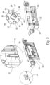
- FIG 2 shows the squeegee device 20 of the additive manufacturing system 100.
- the squeegee device 20 comprises a squeegee turret 60 with a cylindrical base body 67, the peripheral surface of which has at least one receptacle 61 into which a coater element 62 is inserted.
- the coater element 62 is designed to apply or remove the powder material 41 onto or from the building board 31 of the building container 30 .
- the squeegee turret 60 preferably has a plurality of receptacles 61 into which further coater elements 62 are inserted.
- the coating element 62 can be a rubber lip or a blade made of metal and/or ceramic.
- a cleaning element 63 which is designed to remove powder residues after the additive manufacturing of the workpiece, is positioned in one of the plurality of receptacles 61 of the squeegee device 60.
- the cleaning element 63 can be, for example, a silicone-impregnated brush and/or a carbon brush.
- the cleaning element 63 can clean an interface 12 between a floor 11 of the build chamber 10 and the powder container 40, the powder overflow container 35 and/or the build container 30.
- the squeegee turret 60 can rotate and switch over to the cleaning element 63 so that this faces the bottom 11 of the build chamber 10 .
- the cleaning element 63 can thus remove the powder residue and/or the welding spatter from the bottom 11 of the construction chamber 10 and/or the interface 12 between the bottom 11 and the containers 30, 40, 35. In this way it can be ensured that no powder residue can be carried over during the removal of the container.
- an illumination element 64 is positioned in one of the multiple receptacles 61 of the squeegee device 60, which is designed to illuminate the powder layer for recording the image data.
- the lighting element 64 includes at least one Lamps, such as LED, halogen, laser, neon and/or xenon lamp, preferably NIR (Near Infrared) - LED.
- the coater element 62, the cleaning element 63 and/or the lighting element 64 extend at least partially in the longitudinal direction of the cylindrical body 67 of the doctor turret 60.
- the squeegee device 20 also includes a support body 24 to which the squeegee turret 60 is detachably attached by means of a changing mechanism element 66 .
- the changing mechanism element 66 can ensure that the squeegee turret 60 can be removed from the squeegee device 20 easily and quickly.
- the changing mechanism element 66 can have a positive, non-positive, (electro)magnetic and/or clamp connection.
- the squeegee device 20 further comprises at least one distance sensor 21 for detecting a distance between the building board 31 and the coater element 62.
- the distance sensor 21 is arranged on a bottom side 26 of the squeegee device 20 in such a way that it faces the bottom 11 of the build chamber 10.
- the squeegee device 20 preferably includes a plurality of distance sensors 21 in order to enable precise measurement of the distance between the building board 31 and the coater element 62 .
- the distance sensor 21 can also be designed to measure the distance between the coater element 62 and a base plate 43 of the powder container 40 in order to determine the amount of powder material 41 currently present in the powder container 40 .
- the distance sensor 21 can be, for example, an inductive sensor, an ultrasonic sensor or a radar sensor, which enables contactless distance measurement.
- the squeegee device 20 also includes a contact sensor 25 for detecting contact between the building board 31 and the coater element 62.
- the contact sensor 25 is arranged on the bottom side 26 of the squeegee device 20 in such a way that it faces the building board 31 of the building container 30.
- the construction container 30 is coupled to a lifting device 32 which is designed to raise and/or lower the construction panel 31 within the construction container 30 .
- the base plate 43 of the powder container 40 can also be connected to a separate lifting device (not shown) in order to convey the fresh powder material 41 to the bottom 11 of the build chamber.
- the building board 31 can be lifted to the floor 11 of the building chamber 10 by means of the lifting device 32 .
- the contact sensor 25 can detect the contact with the building board 31 at several points.
- the squeegee device 20 can have two or more contact sensors 25 which can be arranged at a distance from one another on the bottom side 26 of the squeegee device 20 . In this way, a position of the building board 31, in particular the height and inclination relative to a horizontal plane, can be precisely detected and corrected according to the measurement results.
- the squeegee device 20 further comprises a fastening element 22 for the detachable fastening of a container cover 33, 42 of the construction container 30 and/or the powder container 40 and a height adjustment element 23 for height mobility of the container cover 33, 42 held.
- a fastening element 22 for the detachable fastening of a container cover 33, 42 of the construction container 30 and/or the powder container 40
- a height adjustment element 23 for height mobility of the container cover 33, 42 held.
- the doctor device 20 moves over a container cover 33, 42 of these containers 30, 40.
- the carrier body 24 of the doctor device 20 can be moved by means of the fastening element 22, which is designed like a T-shaped groove, positively grip the container lid 33, 42 via a connecting element 34 located thereon, which is designed like a T-shaped projection.
- the squeegee device 20 preferably comprises at least two fastening elements 22 and the container lid 33, 42 comprises at least two connecting elements 34, 43 in order to be able to lift the lid 33, 42 of the respective container 30, 40 evenly in the vertical direction.
- the height adjustment element 23 can lift the container lid 33, 42, which has been removed from either the powder container 40 or the construction container 30, in the vertical direction in order to ensure contactless transport of the lid 33, 42 with the construction field. So that the container lid 33, 42 cannot become detached from the doctor device 20 during transport, its movement is restricted by a cam 65 arranged in the doctor turret 60.
- the cam 65 can be arranged in an opposite direction relative to the direction of insertion of the cover 33, 42 onto the squeegee device 20. In this way, the container lid 33, 42 cannot fall off when recording the fastening element 22 of the squeegee device 20 slides out, but this is held in place by the cam 65.
- the construction container lid 33 and powder container lid 42 removed from the squeegee device 20 are transported to a storage location (not shown) which is inside the construction chamber 10 but outside the construction field.
- figure 6 shows powder application monitoring during additive manufacturing.
- the powder material 41 When the powder material 41 is applied, line-like structures can arise in the direction of travel of the squeegee device 20 .
- a visibility of such powder application defect can increase most when illuminated by side lighting to create a shadow.
- the powder application error and/or the coating error can be detected indirectly via a characteristic shadow using the optical element 51, preferably the off-axis camera.
- the control unit (not shown) can use the optical device 50 to detect an application quality of the powder material 41 and determine a fault in the coater element 62 currently being used if the application quality of the powder material 41 deviates from the predetermined requirement.
- the squeegee turret 60 can rotate according to the severity of the damage to the current coater element 62 and switch to a next coater element 62 that is in particular error-free.
- figure 7 shows a flowchart of an additive manufacturing process.
- step S0 the build container 30 and the powder container 40 are inserted into the build chamber 10 of the manufacturing system 100 and the build chamber 10 is then rendered inert in order to minimize the oxygen content in the build chamber 10.
- step S010 the cover 33 of the construction container 30 is detachably connected to the fastening element 22 of the squeegee device 20.
- the lid 33 is raised by means of the height adjustment element 23 and transported to the lid storage location by a horizontal movement of the squeegee device 20 .
- step S020 a position of the building board 31 is aligned.
- the building board 31 is raised to the floor 11 of the building chamber 10 by means of the lifting device 32 S021.
- the contact sensor 25 can detect the contact with the building board 31 at several points S022. In this way, a position of the building board 31, in particular height and inclination recorded precisely relative to a horizontal plane and corrected according to the measurement results S023.
- the building board 31 is then lowered slightly more than 3 mm below the calculated building board position (level 0) upon contact S024.
- the building board 31 can thus be located minimally below level 0.
- Level 0 can be, for example, the position of a floor 11 of the build chamber 10, to which a powder container 40, a build container 30 and/or a powder overflow container can be coupled. In this way it can be ensured that the squeegee device 20 does not come into contact with or collide with the building board 31 during operation, since the coater element can be approx. 0.05 mm above level 0.
- the optical element 51 creates a reference image of the building board S025, which is still untouched by the powder material 41.
- step S1 the powder material 41 is applied to the building board 31 by means of the coating element 62 of the squeegee device 20. After the powder layer has been applied, the building board 31 is raised by an amount of 10-100 ⁇ m S2. The squeegee device 20 then removes part of the raised layer of powder.
- step S3 image data of the powder layer on the building board 31 are recorded by means of the optical device 50, preferably the off-axis camera 51.
- step S31 an image-processing algorithm uses the reference image to check whether the building board 31 is still completely covered with powder or whether areas of the building board that are already untouched by the powder are shining through.
- steps S1 to S3 can be repeated with the removal of a 10-100 ⁇ m thick layer of powder. These steps can be repeated until the optical element 51, i.e. Off-axis camera and the associated algorithm minimum residues of powder material 41 on the building board 31 detects.
- the position of the building board 31 can be set as the starting position for additive manufacturing when only a few areas of the building board 31 are still covered with the powder material 41 .
- the control unit of the production system 100 stores S5 the exact horizontal position of the building board 31 in connection with the coater element 62 that is used Steps are repeated to determine an optimal position of the building board 31 for each coater element 62.
Landscapes
- Engineering & Computer Science (AREA)
- Chemical & Material Sciences (AREA)
- Materials Engineering (AREA)
- Manufacturing & Machinery (AREA)
- Physics & Mathematics (AREA)
- Optics & Photonics (AREA)
- Mechanical Engineering (AREA)
- Plasma & Fusion (AREA)
- Automation & Control Theory (AREA)
- Analytical Chemistry (AREA)
Priority Applications (2)
| Application Number | Priority Date | Filing Date | Title |
|---|---|---|---|
| EP21197233.6A EP4151342B1 (fr) | 2021-09-16 | 2021-09-16 | Système de fabrication additive d'une pièce |
| US17/946,133 US20230078772A1 (en) | 2021-09-16 | 2022-09-16 | Manufacturing system for additive manufacturing of a workpiece |
Applications Claiming Priority (1)
| Application Number | Priority Date | Filing Date | Title |
|---|---|---|---|
| EP21197233.6A EP4151342B1 (fr) | 2021-09-16 | 2021-09-16 | Système de fabrication additive d'une pièce |
Publications (2)
| Publication Number | Publication Date |
|---|---|
| EP4151342A1 true EP4151342A1 (fr) | 2023-03-22 |
| EP4151342B1 EP4151342B1 (fr) | 2024-06-26 |
Family
ID=77801630
Family Applications (1)
| Application Number | Title | Priority Date | Filing Date |
|---|---|---|---|
| EP21197233.6A Active EP4151342B1 (fr) | 2021-09-16 | 2021-09-16 | Système de fabrication additive d'une pièce |
Country Status (2)
| Country | Link |
|---|---|
| US (1) | US20230078772A1 (fr) |
| EP (1) | EP4151342B1 (fr) |
Cited By (2)
| Publication number | Priority date | Publication date | Assignee | Title |
|---|---|---|---|---|
| DE102022129042B3 (de) | 2022-11-03 | 2023-09-21 | additiveStream4D GmbH | Kalibriersystem und Kalibrierverfahren zur Kalibrierung eines Bauplattformsystems in einer additiven Fertigungsvorrichtung |
| WO2024094256A1 (fr) | 2022-11-03 | 2024-05-10 | additiveStream4D GmbH | Système d'étalonnage et procédé d'étalonnage pour étalonner un système de plateforme de construction dans un dispositif de fabrication additive |
Citations (9)
| Publication number | Priority date | Publication date | Assignee | Title |
|---|---|---|---|---|
| US20070037509A1 (en) * | 2005-05-31 | 2007-02-15 | Bernd Renz | Method for the manufacture of a molding as well as a sensor unit for the application thereof |
| WO2014095200A1 (fr) * | 2012-12-17 | 2014-06-26 | Arcam Ab | Procédé et appareil d'impression 3d |
| US20150165683A1 (en) * | 2013-12-13 | 2015-06-18 | General Electric Company | Operational performance assessment of additive manufacturing |
| US20160236279A1 (en) * | 2013-09-23 | 2016-08-18 | Renishaw Plc | Additive manufacturing apparatus and method |
| US20180124341A1 (en) * | 2016-10-28 | 2018-05-03 | General Electric Company | Imaging devices for use with additive manufacturing systems and methods of imaging a build layer |
| EP3495077A1 (fr) * | 2016-08-02 | 2019-06-12 | Xi'an Bright Laser Technologies Co., Ltd. | Procédé d'essai de qualité d'étalement de poudre et dispositif de fabrication additive |
| US20190366433A1 (en) * | 2016-09-22 | 2019-12-05 | Siemens Aktiengesellschaft | Producing Workpieces With an Additive Production Method |
| CN111940733A (zh) * | 2020-07-20 | 2020-11-17 | 北京科技大学 | 选区激光熔化过程飞溅氧化物清除及供粉补偿装置和方法 |
| US20210053279A1 (en) * | 2019-08-23 | 2021-02-25 | Canon Kabushiki Kaisha | Method of manufacturing three-dimensionally shaped object, additive manufacturing apparatus, and powder depositing apparatus |
Family Cites Families (2)
| Publication number | Priority date | Publication date | Assignee | Title |
|---|---|---|---|---|
| CN109963698A (zh) * | 2017-01-27 | 2019-07-02 | 惠普发展公司,有限责任合伙企业 | 用于增材制造的自动铺展杆刮板材料定位 |
| DE102018208025A1 (de) * | 2018-05-22 | 2019-11-28 | Robert Bosch Gmbh | Nivelliervorrichtung, Fertigungsanlage und Verfahren |
-
2021
- 2021-09-16 EP EP21197233.6A patent/EP4151342B1/fr active Active
-
2022
- 2022-09-16 US US17/946,133 patent/US20230078772A1/en active Pending
Patent Citations (9)
| Publication number | Priority date | Publication date | Assignee | Title |
|---|---|---|---|---|
| US20070037509A1 (en) * | 2005-05-31 | 2007-02-15 | Bernd Renz | Method for the manufacture of a molding as well as a sensor unit for the application thereof |
| WO2014095200A1 (fr) * | 2012-12-17 | 2014-06-26 | Arcam Ab | Procédé et appareil d'impression 3d |
| US20160236279A1 (en) * | 2013-09-23 | 2016-08-18 | Renishaw Plc | Additive manufacturing apparatus and method |
| US20150165683A1 (en) * | 2013-12-13 | 2015-06-18 | General Electric Company | Operational performance assessment of additive manufacturing |
| EP3495077A1 (fr) * | 2016-08-02 | 2019-06-12 | Xi'an Bright Laser Technologies Co., Ltd. | Procédé d'essai de qualité d'étalement de poudre et dispositif de fabrication additive |
| US20190366433A1 (en) * | 2016-09-22 | 2019-12-05 | Siemens Aktiengesellschaft | Producing Workpieces With an Additive Production Method |
| US20180124341A1 (en) * | 2016-10-28 | 2018-05-03 | General Electric Company | Imaging devices for use with additive manufacturing systems and methods of imaging a build layer |
| US20210053279A1 (en) * | 2019-08-23 | 2021-02-25 | Canon Kabushiki Kaisha | Method of manufacturing three-dimensionally shaped object, additive manufacturing apparatus, and powder depositing apparatus |
| CN111940733A (zh) * | 2020-07-20 | 2020-11-17 | 北京科技大学 | 选区激光熔化过程飞溅氧化物清除及供粉补偿装置和方法 |
Cited By (2)
| Publication number | Priority date | Publication date | Assignee | Title |
|---|---|---|---|---|
| DE102022129042B3 (de) | 2022-11-03 | 2023-09-21 | additiveStream4D GmbH | Kalibriersystem und Kalibrierverfahren zur Kalibrierung eines Bauplattformsystems in einer additiven Fertigungsvorrichtung |
| WO2024094256A1 (fr) | 2022-11-03 | 2024-05-10 | additiveStream4D GmbH | Système d'étalonnage et procédé d'étalonnage pour étalonner un système de plateforme de construction dans un dispositif de fabrication additive |
Also Published As
| Publication number | Publication date |
|---|---|
| US20230078772A1 (en) | 2023-03-16 |
| EP4151342B1 (fr) | 2024-06-26 |
Similar Documents
| Publication | Publication Date | Title |
|---|---|---|
| EP4151342B1 (fr) | Système de fabrication additive d'une pièce | |
| EP3538298B1 (fr) | Procédé pour calibrer un dispositif de balayage et machine d'usinage | |
| EP3084347B1 (fr) | Procédé d'exécution et de contrôle d'une étape d'usinage sur une pièce | |
| DE102014205726B4 (de) | Verfahren zum bestimmen von profildaten für ein kantenmerkmal in einem inspektionssystem mit maschineller bildverarbeitung | |
| EP2983898B1 (fr) | Procédé d'étalonnage automatique d'un dispositif de fabrication additive d'un objet tridimensionnel | |
| DE3318980C2 (de) | Vorrichtung zum Justieren beim Projektionskopieren von Masken | |
| EP3362262A1 (fr) | Procédé et dispositif de fabrication d'un objet tridimensionnel | |
| EP3610500B1 (fr) | Appareil de réception de composant avec capteur optique | |
| DE4222804A1 (de) | Einrichtung und verfahren zur automatischen visuellen pruefung elektrischer und elektronischer baueinheiten | |
| DE112018008046T5 (de) | Vorrichtung zur additiven fertigung | |
| EP3625029B1 (fr) | Système de mesure pour un dispositif de fabrication additive d'un objet tridimensionnel | |
| DE102017212371B4 (de) | Bestimmung einer Marke in einem Datensatz mit mittels zumindest eines Laserscanners erfassten dreidimensionalen Oberflächen-Koordinaten einer Szene | |
| DE102017203853A1 (de) | Platinenuntersuchungsvorrichtung | |
| DE102019211028B4 (de) | Robotersystem und Kalibrierverfahren | |
| DE3809221A1 (de) | Verfahren zum detektieren von fehlstellen an pressteilen oder anderen werkstuecken und vorrichtung zur durchfuehrung des verfahrens | |
| DE102021000808A1 (de) | Prüfverfahren und Prüfsystem für säulenförmige Wabenstruktur aus Keramik | |
| DE202009005329U1 (de) | Schneidevorrichtung | |
| DE102018217940A1 (de) | Verfahren und Bearbeitungsmaschine zum Bearbeiten eines Werkstücks | |
| DE102022204693A1 (de) | Schutzfilm-dickenmessverfahren | |
| DE10307358B3 (de) | Verfahren und Vorrichtung zum Scannen eines Halbleiter-Wafers | |
| WO2022171621A1 (fr) | Procédé d'optimisation d'un temps d'usinage d'un processus d'usinage laser, procédé de réalisation d'un processus d'usinage laser sur une pièce, et système d'usinage laser conçu pour réaliser ce processus | |
| EP3880392A1 (fr) | Procédé d'étalonnage amélioré pour une installation destinée à générer des pièces tridimensionnelles sur la base d'un lit de poudre au moyen d'un rayonnement électromagnétique | |
| DE102013112666A1 (de) | Verfahren zum Ablösen von Halbleiterchips von einer Folie | |
| EP1443542B1 (fr) | Procédé et dispositif pour le contrôle du bord d'objects circulaires | |
| DE102022100717A1 (de) | Automatisierte strahlabtastkalibrierung, -ausrichtung und - einstellung |
Legal Events
| Date | Code | Title | Description |
|---|---|---|---|
| PUAI | Public reference made under article 153(3) epc to a published international application that has entered the european phase |
Free format text: ORIGINAL CODE: 0009012 |
|
| STAA | Information on the status of an ep patent application or granted ep patent |
Free format text: STATUS: REQUEST FOR EXAMINATION WAS MADE |
|
| 17P | Request for examination filed |
Effective date: 20220802 |
|
| AK | Designated contracting states |
Kind code of ref document: A1 Designated state(s): AL AT BE BG CH CY CZ DE DK EE ES FI FR GB GR HR HU IE IS IT LI LT LU LV MC MK MT NL NO PL PT RO RS SE SI SK SM TR |
|
| RAP3 | Party data changed (applicant data changed or rights of an application transferred) |
Owner name: UNITED GRINDING GROUP MANAGEMENT AG |
|
| STAA | Information on the status of an ep patent application or granted ep patent |
Free format text: STATUS: EXAMINATION IS IN PROGRESS |
|
| 17Q | First examination report despatched |
Effective date: 20230502 |
|
| GRAP | Despatch of communication of intention to grant a patent |
Free format text: ORIGINAL CODE: EPIDOSNIGR1 |
|
| STAA | Information on the status of an ep patent application or granted ep patent |
Free format text: STATUS: GRANT OF PATENT IS INTENDED |
|
| INTG | Intention to grant announced |
Effective date: 20240319 |
|
| GRAS | Grant fee paid |
Free format text: ORIGINAL CODE: EPIDOSNIGR3 |
|
| GRAA | (expected) grant |
Free format text: ORIGINAL CODE: 0009210 |
|
| STAA | Information on the status of an ep patent application or granted ep patent |
Free format text: STATUS: THE PATENT HAS BEEN GRANTED |
|
| AK | Designated contracting states |
Kind code of ref document: B1 Designated state(s): AL AT BE BG CH CY CZ DE DK EE ES FI FR GB GR HR HU IE IS IT LI LT LU LV MC MK MT NL NO PL PT RO RS SE SI SK SM TR |
|
| REG | Reference to a national code |
Ref country code: GB Ref legal event code: FG4D Free format text: NOT ENGLISH |
|
| REG | Reference to a national code |
Ref country code: CH Ref legal event code: EP |
|
| REG | Reference to a national code |
Ref country code: DE Ref legal event code: R096 Ref document number: 502021004097 Country of ref document: DE |
|
| P01 | Opt-out of the competence of the unified patent court (upc) registered |
Free format text: CASE NUMBER: APP_36453/2024 Effective date: 20240618 |
|
| REG | Reference to a national code |
Ref country code: NL Ref legal event code: FP |