EP4150987B1 - Reporting granularity and measurement period for positioning reference signal (prs) measurements - Google Patents
Reporting granularity and measurement period for positioning reference signal (prs) measurements Download PDFInfo
- Publication number
- EP4150987B1 EP4150987B1 EP21729167.3A EP21729167A EP4150987B1 EP 4150987 B1 EP4150987 B1 EP 4150987B1 EP 21729167 A EP21729167 A EP 21729167A EP 4150987 B1 EP4150987 B1 EP 4150987B1
- Authority
- EP
- European Patent Office
- Prior art keywords
- prs
- periodicity
- resources
- positioning
- resource
- Prior art date
- Legal status (The legal status is an assumption and is not a legal conclusion. Google has not performed a legal analysis and makes no representation as to the accuracy of the status listed.)
- Active
Links
Images





Classifications
-
- H—ELECTRICITY
- H04—ELECTRIC COMMUNICATION TECHNIQUE
- H04W—WIRELESS COMMUNICATION NETWORKS
- H04W64/00—Locating users or terminals or network equipment for network management purposes, e.g. mobility management
- H04W64/006—Locating users or terminals or network equipment for network management purposes, e.g. mobility management with additional information processing, e.g. for direction or speed determination
-
- G—PHYSICS
- G01—MEASURING; TESTING
- G01S—RADIO DIRECTION-FINDING; RADIO NAVIGATION; DETERMINING DISTANCE OR VELOCITY BY USE OF RADIO WAVES; LOCATING OR PRESENCE-DETECTING BY USE OF THE REFLECTION OR RERADIATION OF RADIO WAVES; ANALOGOUS ARRANGEMENTS USING OTHER WAVES
- G01S5/00—Position-fixing by co-ordinating two or more direction or position line determinations; Position-fixing by co-ordinating two or more distance determinations
- G01S5/02—Position-fixing by co-ordinating two or more direction or position line determinations; Position-fixing by co-ordinating two or more distance determinations using radio waves
- G01S5/0205—Details
- G01S5/0221—Receivers
-
- G—PHYSICS
- G01—MEASURING; TESTING
- G01S—RADIO DIRECTION-FINDING; RADIO NAVIGATION; DETERMINING DISTANCE OR VELOCITY BY USE OF RADIO WAVES; LOCATING OR PRESENCE-DETECTING BY USE OF THE REFLECTION OR RERADIATION OF RADIO WAVES; ANALOGOUS ARRANGEMENTS USING OTHER WAVES
- G01S5/00—Position-fixing by co-ordinating two or more direction or position line determinations; Position-fixing by co-ordinating two or more distance determinations
- G01S5/02—Position-fixing by co-ordinating two or more direction or position line determinations; Position-fixing by co-ordinating two or more distance determinations using radio waves
- G01S5/0205—Details
- G01S5/0236—Assistance data, e.g. base station almanac
-
- H—ELECTRICITY
- H04—ELECTRIC COMMUNICATION TECHNIQUE
- H04L—TRANSMISSION OF DIGITAL INFORMATION, e.g. TELEGRAPHIC COMMUNICATION
- H04L5/00—Arrangements affording multiple use of the transmission path
- H04L5/003—Arrangements for allocating sub-channels of the transmission path
- H04L5/0048—Allocation of pilot signals, i.e. of signals known to the receiver
-
- H—ELECTRICITY
- H04—ELECTRIC COMMUNICATION TECHNIQUE
- H04L—TRANSMISSION OF DIGITAL INFORMATION, e.g. TELEGRAPHIC COMMUNICATION
- H04L5/00—Arrangements affording multiple use of the transmission path
- H04L5/003—Arrangements for allocating sub-channels of the transmission path
- H04L5/0048—Allocation of pilot signals, i.e. of signals known to the receiver
- H04L5/0051—Allocation of pilot signals, i.e. of signals known to the receiver of dedicated pilots, i.e. pilots destined for a single user or terminal
-
- H—ELECTRICITY
- H04—ELECTRIC COMMUNICATION TECHNIQUE
- H04W—WIRELESS COMMUNICATION NETWORKS
- H04W24/00—Supervisory, monitoring or testing arrangements
- H04W24/08—Testing, supervising or monitoring using real traffic
-
- H—ELECTRICITY
- H04—ELECTRIC COMMUNICATION TECHNIQUE
- H04W—WIRELESS COMMUNICATION NETWORKS
- H04W24/00—Supervisory, monitoring or testing arrangements
- H04W24/10—Scheduling measurement reports ; Arrangements for measurement reports
-
- H—ELECTRICITY
- H04—ELECTRIC COMMUNICATION TECHNIQUE
- H04W—WIRELESS COMMUNICATION NETWORKS
- H04W72/00—Local resource management
- H04W72/04—Wireless resource allocation
- H04W72/044—Wireless resource allocation based on the type of the allocated resource
- H04W72/0453—Resources in frequency domain, e.g. a carrier in FDMA
-
- H—ELECTRICITY
- H04—ELECTRIC COMMUNICATION TECHNIQUE
- H04W—WIRELESS COMMUNICATION NETWORKS
- H04W64/00—Locating users or terminals or network equipment for network management purposes, e.g. mobility management
Definitions
- aspects of the disclosure relate generally to wireless communications.
- Wireless communication systems have developed through various generations, including a first-generation analog wireless phone service (1G), a second-generation (2G) digital wireless phone service (including interim 2.5G and 2.75G networks), a third-generation (3G) high speed data, Internet-capable wireless service and a fourth-generation (4G) service (e.g., Long Term Evolution (LTE) or WiMax).
- 1G first-generation analog wireless phone service
- 2G second-generation digital wireless phone service
- 3G high speed data
- 4G fourth-generation
- 4G fourth-generation
- LTE Long Term Evolution
- PCS personal communications service
- Examples of known cellular systems include the cellular analog advanced mobile phone system (AMPS), and digital cellular systems based on code division multiple access (CDMA), frequency division multiple access (FDMA), time division multiple access (TDMA), the Global System for Mobile communications (GSM), etc.
- CDMA code division multiple access
- FDMA frequency division multiple access
- TDMA time division multiple access
- GSM Global System for Mobile communications
- a fifth generation (5G) wireless standard referred to as New Radio (NR) calls for higher data transfer speeds, greater numbers of connections, and better coverage, among other improvements.
- the 5G standard according to the Next Generation Mobile Networks Alliance, is designed to provide data rates of several tens of megabits per second to each of tens of thousands of users, with 1 gigabit per second to tens of workers on an office floor. Several hundreds of thousands of simultaneous connections should be supported in order to support large sensor deployments. Consequently, the spectral efficiency of 5G mobile communications should be significantly enhanced compared to the current 4G standard. Furthermore, signaling efficiencies should be enhanced and latency should be substantially reduced compared to current standards.
- US 2019/037338 discloses on-demand resource allocation for location determination of a mobile device in which a UE sends a request to a wireless node for broadcast of an increased quantity of location-related information, such as a positioning reference signal or location assistance data, for a wireless access type and the wireless node broadcasts the increased quantity of location-related information using the wireless access type.
- WO 2020/027604 A1 and WO 2019/162513 A1 also form part of the related prior art.
- sequences of actions to be performed by, for example, elements of a computing device. It will be recognized that various actions described herein can be performed by specific circuits (e.g., application specific integrated circuits (ASICs)), by program instructions being executed by one or more processors, or by a combination of both. Additionally, the sequence(s) of actions described herein can be considered to be embodied entirely within any form of non-transitory computer-readable storage medium having stored therein a corresponding set of computer instructions that, upon execution, would cause or instruct an associated processor of a device to perform the functionality described herein.
- ASICs application specific integrated circuits
- a UE may be any wireless communication device (e.g., a mobile phone, router, tablet computer, laptop computer, consumer asset locating device, wearable (e.g., smartwatch, glasses, augmented reality (AR) / virtual reality (VR) headset, etc.), vehicle (e.g., automobile, motorcycle, bicycle, etc.), Internet of Things (IoT) device, etc.) used by a user to communicate over a wireless communications network.
- a UE may be mobile or may (e.g., at certain times) be stationary, and may communicate with a radio access network (RAN).
- RAN radio access network
- UE may be referred to interchangeably as an "access terminal” or “AT,” a “client device,” a “wireless device,” a “subscriber device,” a “subscriber terminal,” a “subscriber station,” a “user terminal” or “UT,” a “mobile device,” a “mobile terminal,” a “mobile station,” or variations thereof.
- AT access terminal
- client device a “wireless device”
- subscriber device a “subscriber terminal”
- a subscriber station a “user terminal” or “UT”
- UT a “mobile device”
- mobile terminal a mobile terminal
- mobile station or variations thereof.
- UEs can communicate with a core network via a RAN, and through the core network the UEs can be connected with external networks such as the Internet and with other UEs.
- WLAN wireless local area network
- IEEE Institute of Electrical and Electronics Engineers
- a base station may operate according to one of several RATs in communication with UEs depending on the network in which it is deployed, and may be alternatively referred to as an access point (AP), a network node, a NodeB, an evolved NodeB (eNB), a next generation eNB (ng-eNB), a New Radio (NR) Node B (also referred to as a gNB or gNodeB), etc.
- AP access point
- eNB evolved NodeB
- ng-eNB next generation eNB
- NR New Radio
- a base station may be used primarily to support wireless access by UEs, including supporting data, voice, and/or signaling connections for the supported UEs.
- a base station may provide purely edge node signaling functions while in other systems it may provide additional control and/or network management functions.
- a communication link through which UEs can send signals to a base station is called an uplink (UL) channel (e.g., a reverse traffic channel, a reverse control channel, an access channel, etc.).
- a communication link through which the base station can send signals to UEs is called a downlink (DL) or forward link channel (e.g., a paging channel, a control channel, a broadcast channel, a forward traffic channel, etc.).
- DL downlink
- forward link channel e.g., a paging channel, a control channel, a broadcast channel, a forward traffic channel, etc.
- traffic channel can refer to either an uplink / reverse or downlink / forward traffic channel.
- a base station may not support wireless access by UEs (e.g., may not support data, voice, and/or signaling connections for UEs), but may instead transmit reference signals to UEs to be measured by the UEs, and/or may receive and measure signals transmitted by the UEs.
- a base station may be referred to as a positioning beacon (e.g., when transmitting signals to UEs) and/or as a location measurement unit (e.g., when receiving and measuring signals from UEs).
- the base stations 102 may collectively form a RAN and interface with a core network 170 (e.g., an evolved packet core (EPC) or a 5G core (5GC)) through backhaul links 122, and through the core network 170 to one or more location servers 172 (e.g., a location management function (LMF) or a secure user plane location (SUPL) location platform (SLP)).
- the location server(s) 172 may be part of core network 170 or may be external to core network 170.
- different cells may be configured according to different protocol types (e.g., machine-type communication (MTC), narrowband IoT (NB-IoT), enhanced mobile broadband (eMBB), or others) that may provide access for different types of UEs.
- MTC machine-type communication
- NB-IoT narrowband IoT
- eMBB enhanced mobile broadband
- a cell may refer to either or both of the logical communication entity and the base station that supports it, depending on the context.
- TRP is typically the physical transmission point of a cell
- the terms “cell” and “TRP” may be used interchangeably.
- the term “cell” may also refer to a geographic coverage area of a base station (e.g., a sector), insofar as a carrier frequency can be detected and used for communication within some portion of geographic coverage areas 110.
- While neighboring macro cell base station 102 geographic coverage areas 110 may partially overlap (e.g., in a handover region), some of the geographic coverage areas 110 may be substantially overlapped by a larger geographic coverage area 110.
- a small cell base station 102' (labeled "SC” for "small cell") may have a geographic coverage area 110' that substantially overlaps with the geographic coverage area 110 of one or more macro cell base stations 102.
- a network that includes both small cell and macro cell base stations may be known as a heterogeneous network.
- a heterogeneous network may also include home eNBs (HeNBs), which may provide service to a restricted group known as a closed subscriber group (CSG).
- HeNBs home eNBs
- CSG closed subscriber group
- the communication links 120 between the base stations 102 and the UEs 104 may include uplink (also referred to as reverse link) transmissions from a UE 104 to a base station 102 and/or downlink (DL) (also referred to as forward link) transmissions from a base station 102 to a UE 104.
- the communication links 120 may use MIMO antenna technology, including spatial multiplexing, beamforming, and/or transmit diversity.
- the communication links 120 may be through one or more carrier frequencies. Allocation of carriers may be asymmetric with respect to downlink and uplink (e.g., more or less carriers may be allocated for downlink than for uplink).
- the wireless communications system 100 may further include a wireless local area network (WLAN) access point (AP) 150 in communication with WLAN stations (STAs) 152 via communication links 154 in an unlicensed frequency spectrum (e.g., 5 GHz).
- WLAN STAs 152 and/or the WLAN AP 150 may perform a clear channel assessment (CCA) or listen before talk (LBT) procedure prior to communicating in order to determine whether the channel is available.
- CCA clear channel assessment
- LBT listen before talk
- the small cell base station 102' may operate in a licensed and/or an unlicensed frequency spectrum. When operating in an unlicensed frequency spectrum, the small cell base station 102' may employ LTE or NR technology and use the same 5 GHz unlicensed frequency spectrum as used by the WLAN AP 150. The small cell base station 102', employing LTE / 5G in an unlicensed frequency spectrum, may boost coverage to and/or increase capacity of the access network.
- NR in unlicensed spectrum may be referred to as NR-U.
- LTE in an unlicensed spectrum may be referred to as LTE-U, licensed assisted access (LAA), or MulteFire.
- the wireless communications system 100 may further include a millimeter wave (mmW) base station 180 that may operate in mmW frequencies and/or near mmW frequencies in communication with a UE 182.
- Extremely high frequency (EHF) is part of the RF in the electromagnetic spectrum. EHF has a range of 30 GHz to 300 GHz and a wavelength between 1 millimeter and 10 millimeters. Radio waves in this band may be referred to as a millimeter wave.
- Near mmW may extend down to a frequency of 3 GHz with a wavelength of 100 millimeters.
- the super high frequency (SHF) band extends between 3 GHz and 30 GHz, also referred to as centimeter wave.
- the mmW base station 180 and the UE 182 may utilize beamforming (transmit and/or receive) over a mmW communication link 184 to compensate for the extremely high path loss and short range.
- one or more base stations 102 may also transmit using mmW or near mmW and beamforming. Accordingly, it will be appreciated that the foregoing illustrations are merely examples and should not be construed to limit the various aspects disclosed herein.
- Transmit beamforming is a technique for focusing an RF signal in a specific direction.
- a network node e.g., a base station
- transmit beamforming the network node determines where a given target device (e.g., a UE) is located (relative to the transmitting network node) and projects a stronger downlink RF signal in that specific direction, thereby providing a faster (in terms of data rate) and stronger RF signal for the receiving device(s).
- a network node can control the phase and relative amplitude of the RF signal at each of the one or more transmitters that are broadcasting the RF signal.
- a network node may use an array of antennas (referred to as a "phased array” or an “antenna array”) that creates a beam of RF waves that can be "steered” to point in different directions, without actually moving the antennas.
- the RF current from the transmitter is fed to the individual antennas with the correct phase relationship so that the radio waves from the separate antennas add together to increase the radiation in a desired direction, while cancelling to suppress radiation in undesired directions.
- Transmit beams may be quasi-co-located, meaning that they appear to the receiver (e.g., a UE) as having the same parameters, regardless of whether or not the transmitting antennas of the network node themselves are physically co-located.
- the receiver e.g., a UE
- QCL relation of a given type means that certain parameters about a second reference RF signal on a second beam can be derived from information about a source reference RF signal on a source beam.
- the receiver can use the source reference RF signal to estimate the Doppler shift, Doppler spread, average delay, and delay spread of a second reference RF signal transmitted on the same channel.
- Transmit and receive beams may be spatially related.
- a spatial relation means that parameters for a second beam (e.g., a transmit or receive beam) for a second reference signal can be derived from information about a first beam (e.g., a receive beam or a transmit beam) for a first reference signal.
- a UE may use a particular receive beam to receive a reference downlink reference signal (e.g., synchronization signal block (SSB)) from a base station.
- the UE can then form a transmit beam for sending an uplink reference signal (e.g., sounding reference signal (SRS)) to that base station based on the parameters of the receive beam.
- an uplink reference signal e.g., sounding reference signal (SRS)
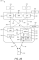
- an ng-eNB 224 may also be connected to the 5GC 210 via NG-C 215 to the control plane functions 214 and NG-U 213 to user plane functions 212. Further, ng-eNB 224 may directly communicate with gNB 222 via a backhaul connection 223.
- a Next Generation RAN (NG-RAN) 220 may have one or more gNBs 222, while other configurations include one or more of both ng-eNBs 224 and gNBs 222. Either (or both) gNB 222 or ng-eNB 224 may communicate with one or more UEs 204 (e.g., any of the UEs described herein).
- the AMF 264 retrieves the security material from the AUSF.
- the functions of the AMF 264 also include security context management (SCM).
- SCM receives a key from the SEAF that it uses to derive access-network specific keys.
- the functionality of the AMF 264 also includes location services management for regulatory services, transport for location services messages between the UE 204 and a location management function (LMF) 270 (which acts as a location server 230), transport for location services messages between the NG-RAN 220 and the LMF 270, evolved packet system (EPS) bearer identifier allocation for interworking with the EPS, and UE 204 mobility event notification.
- LMF location management function
- EPS evolved packet system
- the AMF 264 also supports functionalities for non-3GPP (Third Generation Partnership Project) access networks.
- Functions of the UPF 262 include acting as an anchor point for intra-/inter-RAT mobility (when applicable), acting as an external protocol data unit (PDU) session point of interconnect to a data network (not shown), providing packet routing and forwarding, packet inspection, user plane policy rule enforcement (e.g., gating, redirection, traffic steering), lawful interception (user plane collection), traffic usage reporting, quality of service (QoS) handling for the user plane (e.g., uplink/ downlink rate enforcement, reflective QoS marking in the downlink), uplink traffic verification (service data flow (SDF) to QoS flow mapping), transport level packet marking in the uplink and downlink, downlink packet buffering and downlink data notification triggering, and sending and forwarding of one or more "end markers" to the source RAN node.
- the UPF 262 may also support transfer of location services messages over a user plane between the UE 204 and a location server, such as an SLP 272.
- the functions of the SMF 266 include session management, UE Internet protocol (IP) address allocation and management, selection and control of user plane functions, configuration of traffic steering at the UPF 262 to route traffic to the proper destination, control of part of policy enforcement and QoS, and downlink data notification.
- IP Internet protocol
- the interface over which the SMF 266 communicates with the AMF 264 is referred to as the N11 interface.
- LMF 270 may be in communication with the 5GC 260 to provide location assistance for UEs 204.
- the LMF 270 can be implemented as a plurality of separate servers (e.g., physically separate servers, different software modules on a single server, different software modules spread across multiple physical servers, etc.), or alternately may each correspond to a single server.
- the LMF 270 can be configured to support one or more location services for UEs 204 that can connect to the LMF 270 via the core network, 5GC 260, and/or via the Internet (not illustrated).
- the SLP 272 may support similar functions to the LMF 270, but whereas the LMF 270 may communicate with the AMF 264, NG-RAN 220, and UEs 204 over a control plane (e.g., using interfaces and protocols intended to convey signaling messages and not voice or data), the SLP 272 may communicate with UEs 204 and external clients (not shown in FIG. 2B ) over a user plane (e.g., using protocols intended to carry voice and/or data like the transmission control protocol (TCP) and/or IP).
- TCP transmission control protocol
- User plane interface 263 and control plane interface 265 connect the 5GC 260, and specifically the UPF 262 and AMF 264, respectively, to one or more gNBs 222 and/or ng-eNBs 224 in the NG-RAN 220.
- the interface between gNB(s) 222 and/or ng-eNB(s) 224 and the AMF 264 is referred to as the "N2" interface
- the interface between gNB(s) 222 and/or ng-eNB(s) 224 and the UPF 262 is referred to as the "N3" interface.
- the gNB(s) 222 and/or ng-eNB(s) 224 of the NG-RAN 220 may communicate directly with each other via backhaul connections 223, referred to as the "Xn-C" interface.
- One or more of gNBs 222 and/or ng-eNBs 224 may communicate with one or more UEs 204 over a wireless interface, referred to as the "Uu" interface.
- a gNB-CU 226 is a logical node that includes the base station functions of transferring user data, mobility control, radio access network sharing, positioning, session management, and the like, except for those functions allocated exclusively to the gNB-DU(s) 228.
- the gNB-CU 226 hosts the radio resource control (RRC), service data adaptation protocol (SDAP), and packet data convergence protocol (PDCP) protocols of the gNB 222.
- RRC radio resource control
- SDAP service data adaptation protocol
- PDCP packet data convergence protocol
- a gNB-DU 228 is a logical node that hosts the radio link control (RLC), medium access control (MAC), and physical (PHY) layers of the gNB 222. Its operation is controlled by the gNB-CU 226.
- One gNB-DU 228 can support one or more cells, and one cell is supported by only one gNB-DU 228.
- a UE 204 communicates with the gNB-CU 226 via the RRC, SDAP, and PDCP layers and with a gNB-DU 228 via the RLC, MAC, and PHY layers.
- FIGS. 3A , 3B , and 3C illustrate several example components (represented by corresponding blocks) that may be incorporated into a UE 302 (which may correspond to any of the UEs described herein), a base station 304 (which may correspond to any of the base stations described herein), and a network entity 306 (which may correspond to or embody any of the network functions described herein, including the location server 230 and the LMF 270, or alternatively may be independent from the NG-RAN 220 and/or 5GC 210/260 infrastructure depicted in FIGS. 2A and 2B , such as a private network) to support the file transmission operations as taught herein.
- a UE 302 which may correspond to any of the UEs described herein
- a base station 304 which may correspond to any of the base stations described herein
- a network entity 306 which may correspond to or embody any of the network functions described herein, including the location server 230 and the LMF 270, or alternatively may be independent from the NG-
- these components may be implemented in different types of apparatuses in different implementations (e.g., in an ASIC, in a system-on-chip (SoC), etc.).
- the illustrated components may also be incorporated into other apparatuses in a communication system.
- other apparatuses in a system may include components similar to those described to provide similar functionality.
- a given apparatus may contain one or more of the components.
- an apparatus may include multiple transceiver components that enable the apparatus to operate on multiple carriers and/or communicate via different technologies.
- the UE 302 and the base station 304 each include one or more wireless wide area network (WWAN) transceivers 310 and 350, respectively, providing means for communicating (e.g., means for transmitting, means for receiving, means for measuring, means for tuning, means for refraining from transmitting, etc.) via one or more wireless communication networks (not shown), such as an NR network, an LTE network, a GSM network, and/or the like.
- WWAN wireless wide area network
- wireless receiver circuitry may include or be coupled to a plurality of antennas (e.g., antennas 316, 326, 356, 366), such as an antenna array, that permits the respective apparatus (e.g., UE 302, base station 304) to perform receive beamforming, as described herein.
- the transmitter circuitry and receiver circuitry may share the same plurality of antennas (e.g., antennas 316, 326, 356, 366), such that the respective apparatus can only receive or transmit at a given time, not both at the same time.
- a wireless transceiver e.g., WWAN transceivers 310 and 350, short-range wireless transceivers 320 and 360
- NLM network listen module
- processors 332, 384, and 394 may include, for example, one or more general purpose processors, multi-core processors, central processing units (CPUs), ASICs, digital signal processors (DSPs), field programmable gate arrays (FPGAs), other programmable logic devices or processing circuitry, or various combinations thereof.
- the positioning component 342, 388, and 398 may be memory modules stored in the memories 340, 386, and 396, respectively, that, when executed by the processors 332, 384, and 394 (or a modem processing system, another processing system, etc.), cause the UE 302, the base station 304, and the network entity 306 to perform the functionality described herein.
- FIG. 3A illustrates possible locations of the positioning component 342, which may be, for example, part of the one or more WWAN transceivers 310, the memory 340, the one or more processors 332, or any combination thereof, or may be a standalone component.
- FIG. 3A illustrates possible locations of the positioning component 342, which may be, for example, part of the one or more WWAN transceivers 310, the memory 340, the one or more processors 332, or any combination thereof, or may be a standalone component.
- the UE 302 includes a user interface 346 providing means for providing indications (e.g., audible and/or visual indications) to a user and/or for receiving user input (e.g., upon user actuation of a sensing device such a keypad, a touch screen, a microphone, and so on).
- a user interface 346 providing means for providing indications (e.g., audible and/or visual indications) to a user and/or for receiving user input (e.g., upon user actuation of a sensing device such a keypad, a touch screen, a microphone, and so on).
- the base station 304 and the network entity 306 may also include user interfaces.
- the symbols on each subcarrier, and the reference signal are recovered and demodulated by determining the most likely signal constellation points transmitted by the base station 304. These soft decisions may be based on channel estimates computed by a channel estimator. The soft decisions are then decoded and de-interleaved to recover the data and control signals that were originally transmitted by the base station 304 on the physical channel. The data and control signals are then provided to the one or more processors 332, which implements Layer-3 (L3) and Layer-2 (L2) functionality.
- L3 Layer-3
- L2 Layer-2
- Channel estimates derived by the channel estimator from a reference signal or feedback transmitted by the base station 304 may be used by the transmitter 314 to select the appropriate coding and modulation schemes, and to facilitate spatial processing.
- the spatial streams generated by the transmitter 314 may be provided to different antenna(s) 316.
- the transmitter 314 may modulate an RF carrier with a respective spatial stream for transmission.
- the uplink transmission is processed at the base station 304 in a manner similar to that described in connection with the receiver function at the UE 302.
- the receiver 352 receives a signal through its respective antenna(s) 356.
- the receiver 352 recovers information modulated onto an RF carrier and provides the information to the one or more processors 384.
- the one or more processors 384 provides demultiplexing between transport and logical channels, packet reassembly, deciphering, header decompression, control signal processing to recover IP packets from the UE 302. IP packets from the one or more processors 384 may be provided to the core network.
- the one or more processors 384 are also responsible for error detection.
- a particular implementation of UE 302 may omit the WWAN transceiver(s) 310 (e.g., a wearable device or tablet computer or PC or laptop may have Wi-Fi and/or Bluetooth capability without cellular capability), or may omit the short-range wireless transceiver(s) 320 (e.g., cellular-only, etc.), or may omit the SPS receiver 330, or may omit the sensor(s) 344, and so on.
- WWAN transceiver(s) 310 e.g., a wearable device or tablet computer or PC or laptop may have Wi-Fi and/or Bluetooth capability without cellular capability
- the short-range wireless transceiver(s) 320 e.g., cellular-only, etc.
- SPS receiver 330 e.g., cellular-only, etc.
- a particular implementation of the base station 304 may omit the WWAN transceiver(s) 350 (e.g., a Wi-Fi "hotspot" access point without cellular capability), or may omit the short-range wireless transceiver(s) 360 (e.g., cellular-only, etc.), or may omit the SPS receiver 370, and so on.
- WWAN transceiver(s) 350 e.g., a Wi-Fi "hotspot" access point without cellular capability
- the short-range wireless transceiver(s) 360 e.g., cellular-only, etc.
- SPS receiver 370 e.g., SPS receiver
- the various components of the UE 302, the base station 304, and the network entity 306 may be communicatively coupled to each other over data buses 334, 382, and 392, respectively.
- the data buses 334, 382, and 392 may form, or be part of, a communication interface of the UE 302, the base station 304, and the network entity 306, respectively.
- the data buses 334, 382, and 392 may provide communication between them.
- FIGS. 3A , 3B , and 3C may be implemented in various ways.
- the components of FIGS. 3A , 3B , and 3C may be implemented in one or more circuits such as, for example, one or more processors and/or one or more ASICs (which may include one or more processors).
- each circuit may use and/or incorporate at least one memory component for storing information or executable code used by the circuit to provide this functionality.
- some or all of the functionality represented by blocks 310 to 346 may be implemented by processor and memory component(s) of the UE 302 (e.g., by execution of appropriate code and/or by appropriate configuration of processor components).
- some or all of the functionality represented by blocks 350 to 388 may be implemented by processor and memory component(s) of the base station 304 (e.g., by execution of appropriate code and/or by appropriate configuration of processor components). Also, some or all of the functionality represented by blocks 390 to 398 may be implemented by processor and memory component(s) of the network entity 306 (e.g., by execution of appropriate code and/or by appropriate configuration of processor components). For simplicity, various operations, acts, and/or functions are described herein as being performed “by a UE,” “by a base station,” “by a network entity,” etc.
- the network entity 306 may be implemented as a core network component. In other designs, the network entity 306 may be distinct from a network operator or operation of the cellular network infrastructure (e.g., NG RAN 220 and/or 5GC 210/260). For example, the network entity 306 may be a component of a private network that may be configured to communicate with the UE 302 via the base station 304 or independently from the base station 304 (e.g., over a non-cellular communication link, such as WiFi).
- a non-cellular communication link such as WiFi
- NR supports a number of cellular network-based positioning technologies, including downlink-based, uplink-based, and downlink-and-uplink-based positioning methods.
- Downlink-based positioning methods include observed time difference of arrival (OTDOA) in LTE, downlink time difference of arrival (DL-TDOA) in NR, and downlink angle-of-departure (DL-AoD) in NR.
- OTDOA observed time difference of arrival
- DL-TDOA downlink time difference of arrival
- DL-AoD downlink angle-of-departure
- a UE measures the differences between the times of arrival (ToAs) of reference signals (e.g., positioning reference signals (PRS)) received from pairs of base stations, referred to as reference signal time difference (RSTD) or time difference of arrival (TDOA) measurements, and reports them to a positioning entity.
- ToAs times of arrival
- PRS positioning reference signals
- RSTD reference signal time difference
- TDOA time difference of arrival
- the UE receives the identifiers (IDs) of a reference base station (e.g., a serving base station) and multiple non-reference base stations in assistance data.
- the UE measures the RSTD between the reference base station and each of the non-reference base stations. Based on the known locations of the involved base stations and the RSTD measurements, the positioning entity can estimate the UE's location.
- the positioning entity uses a beam report from the UE of received signal strength measurements of multiple downlink transmit beams to determine the angle(s) between the UE and the transmitting base station(s). The positioning entity can then estimate the location of the UE based on the determined angle(s) and the known location(s) of the transmitting base station(s).
- Downlink-and-uplink-based positioning methods include enhanced cell-ID (E-CID) positioning and multi-round-trip-time (RTT) positioning (also referred to as "multi-cell RTT").
- E-CID enhanced cell-ID
- RTT multi-round-trip-time
- an initiator a base station or a UE
- transmits an RTT measurement signal e.g., a PRS or SRS
- a responder a UE or base station
- RTT response signal e.g., an SRS or PRS
- the RTT response signal includes the difference between the ToA of the RTT measurement signal and the transmission time of the RTT response signal, referred to as the reception-to-transmission (Rx-Tx) time difference.
- For 120 kHz SCS ( ⁇ 3), there are eight slots per subframe, 80 slots per frame, the slot duration is 0.125 ms, the symbol duration is 8.33 ⁇ s, and the maximum nominal system bandwidth (in MHz) with a 4K FFT size is 400.
- For 240 kHz SCS ( ⁇ 4), there are 16 slots per subframe, 160 slots per frame, the slot duration is 0.0625 ms, the symbol duration is 4.17 ⁇ s, and the maximum nominal system bandwidth (in MHz) with a 4K FFT size is 800.
- Values for 'N,' 'T,' and 'B' are currently supported.
- Values for 'N' may be selected from the set of ⁇ 0.125, 0.25, 0.5, 1, 2, 4, 8, 12, 16, 20, 25, 30, 35, 40, 45, 50 ⁇ ms.
- values for 'T' may be selected from the set of ⁇ 8, 16, 20, 30, 40, 80, 160, 320, 640, 1280 ⁇ ms
- values for the maximum bandwidth reported by the UE ('B') may be selected from the set of ⁇ 5, 10, 20, 40, 50, 80, 100, 200, 400 ⁇ MHz.
- Type 1 and Type 2 Two categories are defined for the PRS duration calculation: Type 1 and Type 2.
- Type 2 the presence of even one PRS resource within a slot results in the entire slot duration being considered for PRS duration calculation regardless of how many symbols it occupies.
- Type 2 duration calculation is more conservative, but the two types are approximately the same when PRS symbols occupy most of a slot duration. For the purpose of measurement duration, using only the more conservative Type 2 would be preferable over having two separate formulations for Type 1 and Type 2.
- the present disclosure proposes to define the RSTD measurement period based on the Type 2 PRS duration calculation.
- the RSTD measurement period for a Type 1 PRS duration calculation should be no longer than Type 2.
- FIG. 9 is a diagram 900 of several DL-PRS resources spanning a given time duration in milliseconds, according to aspects of the disclosure.
- time is represented horizontally and frequency is represented vertically.
- Each block represents a symbol in the time domain and some amount of bandwidth in the frequency domain.
- each of the three PRS resources there are three DL-PRS resources (differentiated by different hashing) that each have a repetition factor of four within a slot (14 symbols).
- the DL-PRS resources may be part of the same or different DL-PRS resource sets.
- a repetition factor of four means that each of the three PRS resources is repeated four times (i.e., is transmitted four times) within a slot.
- the DL-PRS resources have a time gap of one symbol, meaning that each repetition of a PRS resource starts on the first symbol after the previous repetition of that PRS resource.
- the four repetitions of each of the three PRS resources are grouped together in four consecutive symbols.
- the first two slots correspond to the first and last slots of a PRS occasion or instance.
- the length of the PRS occasion is denoted L PRS (labeled "L_PRS").
- L PRS is the time from the first symbol of the first DL-PRS resource of the PRS occasion to the last symbol of the last DL-PRS resource of the PRS occasion.
- L PRS spans L PRS slots, that is, from slot '0' to slot 'L PRS -1' (labeled "L_PRS-1").
- the PRS periodicity that is, the time from the first repetition of the first DL-PRS resource of a first PRS instance to the same first repetition of the same first DL-PRS resource of the next PRS instance, is represented as T PRS (labeled "T_PRS").
- T_PRS the PRS occasion is illustrated as spanning T PRS slots, that is, from slot '0' to slot 'T PRS -1' (labeled "T_PRS-1").
- a UE may measure, or sample, one or more repetitions of a PRS resource in a slot, depending on the UE's reported capabilities for 'N' (the duration of DL-PRS symbols in milliseconds the UE can process every 'T' ms) and 'T' (the number of milliseconds within which the UE can process a duration 'N' ms of DL-PRS). Such measurements or samples may also be referred to as measurement instances. If L PRS is less than or equal to 'N,' then a UE only needs 'T' ms to process the PRS resources.
- the parameter L PRS N N PRS slot N ′ defines the number of measurement instances and the parameter max (T, T PRS
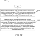
- FIG. 10 illustrates the claimed invention, method 1000 of wireless communication.
- the method 1000 is performed by a UE (e.g., any of the UEs described herein).
- the UE receives, from a network entity (e.g., LMF 270), a configuration of one or more PRS resources to measure during a positioning session, the one or more PRS resources having a PRS periodicity T PRS and a PRS occasion length L PRS .
- operation 1010 may be performed by the one or more WWAN transceivers 310, the one or more processors 332, memory 340, and/or positioning component 342, any or all of which may be considered means for performing this operation.
- the UE measures the one or more PRS resources during a measurement period, wherein the measurement period is based on a number of measurement instances of the one or more PRS resources the UE is expected to process multiplied by a periodicity parameter, wherein the periodicity parameter is based on a PRS processing window of 'T' milliseconds, the PRS periodicity T PRS , and a measurement gap periodicity of at least one measurement gap.
- operation 1020 may be performed by the one or more WWAN transceivers 310, the one or more processors 332, memory 340, and/or positioning component 342, any or all of which may be considered means for performing this operation.
- FIG. 11 illustrates an example method 1100 of wireless communication, according to aspects of the disclosure.
- method 1100 may be performed by a UE (e.g., any of the UEs described herein).
- the UE receives, from a network entity (e.g., LMF 270), a recommendation of a first granularity (e.g., 'k1') for reporting positioning measurements of one or PRS resources during a positioning session.
- a network entity e.g., LMF 270
- a recommendation of a first granularity e.g., 'k1'
- operation 1110 may be performed by the one or more WWAN transceivers 310, the one or more processors 332, memory 340, and/or positioning component 342, any or all of which may be considered means for performing this operation.
- the UE performs one or more positioning measurements of the one or more PRS resources.
- operation 1120 may be performed by the one or more WWAN transceivers 310, the one or more processors 332, memory 340, and/or positioning component 342, any or all of which may be considered means for performing this operation.
- the UE reports the one or more positioning measurements at a second granularity ('k2'), wherein the second granularity is less than or equal to the first granularity and greater than or equal to a minimum granularity, and wherein the minimum granularity is based on a PRS bandwidth parameter associated with the one or more PRS resources.
- operation 1130 may be performed by the one or more WWAN transceivers 310, the one or more processors 332, memory 340, and/or positioning component 342, any or all of which may be considered means for performing this operation.
- a technical advantage of the method 1000 and 1100 is enabling communication between the location server and a UE as to how long a measurement period the UE needs, thereby enabling the location server and/or the UE to determine the latency of a positioning procedure and/or positioning measurements.
- DSP digital signal processor
- ASIC application-specific integrated circuit
- FPGA field-programable gate array
- a general-purpose processor may be a microprocessor, but in the alternative, the processor may be any conventional processor, controller, microcontroller, or state machine.
- a processor may also be implemented as a combination of computing devices, for example, a combination of a DSP and a microprocessor, a plurality of microprocessors, one or more microprocessors in conjunction with a DSP core, or any other such configuration.
- a software module may reside in random access memory (RAM), flash memory, read-only memory (ROM), erasable programmable ROM (EPROM), electrically erasable programmable ROM (EEPROM), registers, hard disk, a removable disk, a CD-ROM, or any other form of storage medium known in the art.
- An example storage medium is coupled to the processor such that the processor can read information from, and write information to, the storage medium.
- the storage medium may be integral to the processor.
- the processor and the storage medium may reside in an ASIC.
- the ASIC may reside in a user terminal (e.g., UE).
- the processor and the storage medium may reside as discrete components in a user terminal.
- the functions described may be implemented in hardware, software, firmware, or any combination thereof. If implemented in software, the functions may be stored on or transmitted over as one or more instructions or code on a computer-readable medium.
- Computer-readable media includes both computer storage media and communication media including any medium that facilitates transfer of a computer program from one place to another.
- a storage media may be any available media that can be accessed by a computer.
- such computer-readable media can comprise RAM, ROM, EEPROM, CD-ROM or other optical disk storage, magnetic disk storage or other magnetic storage devices, or any other medium that can be used to carry or store desired program code in the form of instructions or data structures and that can be accessed by a computer.
Landscapes
- Engineering & Computer Science (AREA)
- Signal Processing (AREA)
- Computer Networks & Wireless Communication (AREA)
- Physics & Mathematics (AREA)
- General Physics & Mathematics (AREA)
- Radar, Positioning & Navigation (AREA)
- Remote Sensing (AREA)
- Mobile Radio Communication Systems (AREA)
- Position Fixing By Use Of Radio Waves (AREA)
Priority Applications (1)
| Application Number | Priority Date | Filing Date | Title |
|---|---|---|---|
| EP23206488.1A EP4290953B1 (en) | 2020-05-15 | 2021-05-10 | Selecting granularity and reporting positioning measurements |
Applications Claiming Priority (3)
| Application Number | Priority Date | Filing Date | Title |
|---|---|---|---|
| US202063025510P | 2020-05-15 | 2020-05-15 | |
| US17/314,258 US12349103B2 (en) | 2020-05-15 | 2021-05-07 | Reporting granularity and measurement period for positioning reference signal (PRS) measurements |
| PCT/US2021/031624 WO2021231325A1 (en) | 2020-05-15 | 2021-05-10 | Reporting granularity and measurement period for positioning reference signal (prs) measurements |
Related Child Applications (2)
| Application Number | Title | Priority Date | Filing Date |
|---|---|---|---|
| EP23206488.1A Division-Into EP4290953B1 (en) | 2020-05-15 | 2021-05-10 | Selecting granularity and reporting positioning measurements |
| EP23206488.1A Division EP4290953B1 (en) | 2020-05-15 | 2021-05-10 | Selecting granularity and reporting positioning measurements |
Publications (3)
| Publication Number | Publication Date |
|---|---|
| EP4150987A1 EP4150987A1 (en) | 2023-03-22 |
| EP4150987B1 true EP4150987B1 (en) | 2025-07-09 |
| EP4150987C0 EP4150987C0 (en) | 2025-07-09 |
Family
ID=78512251
Family Applications (2)
| Application Number | Title | Priority Date | Filing Date |
|---|---|---|---|
| EP21729167.3A Active EP4150987B1 (en) | 2020-05-15 | 2021-05-10 | Reporting granularity and measurement period for positioning reference signal (prs) measurements |
| EP23206488.1A Active EP4290953B1 (en) | 2020-05-15 | 2021-05-10 | Selecting granularity and reporting positioning measurements |
Family Applications After (1)
| Application Number | Title | Priority Date | Filing Date |
|---|---|---|---|
| EP23206488.1A Active EP4290953B1 (en) | 2020-05-15 | 2021-05-10 | Selecting granularity and reporting positioning measurements |
Country Status (8)
| Country | Link |
|---|---|
| US (2) | US12349103B2 (https=) |
| EP (2) | EP4150987B1 (https=) |
| JP (1) | JP7657241B2 (https=) |
| KR (1) | KR20230011286A (https=) |
| CN (1) | CN115606268A (https=) |
| BR (1) | BR112022022334A2 (https=) |
| PH (1) | PH12022552471A1 (https=) |
| WO (1) | WO2021231325A1 (https=) |
Families Citing this family (16)
| Publication number | Priority date | Publication date | Assignee | Title |
|---|---|---|---|---|
| US11765769B2 (en) * | 2021-07-30 | 2023-09-19 | Qualcomm Incorporated | Supplemental positioning reference signal transmission |
| US20240267873A1 (en) * | 2021-08-06 | 2024-08-08 | Sony Group Corporation | Positioning measurement with low latency |
| US12126497B2 (en) * | 2021-09-01 | 2024-10-22 | Parsa Wireless Communications Llc | Prediction-based data transmission by internet of things (IoT) devices |
| EP4396986A4 (en) * | 2021-09-30 | 2025-04-30 | ZTE Corporation | Systems and methods for measurements on positioning reference signals |
| US12015941B2 (en) * | 2021-09-30 | 2024-06-18 | Qualcomm Incorporated | Processing window design for positioning |
| US12363664B2 (en) * | 2021-12-17 | 2025-07-15 | Lenovo (Singapore) Pte. Ltd. | Positioning in a non-terrestrial network |
| US12276743B2 (en) | 2021-12-17 | 2025-04-15 | Lenovo (United States) Inc. | Configuration and reporting in a non-terrestrial network |
| CN116456363B (zh) * | 2022-01-07 | 2026-03-27 | 大唐移动通信设备有限公司 | 一种信息配置方法、传输方法、装置、基站、lmf及终端 |
| US12413364B2 (en) * | 2022-01-07 | 2025-09-09 | Intel Corporation | User equipment behavior and requirements for positioning measurement without gap |
| CN116456267A (zh) * | 2022-01-07 | 2023-07-18 | 北京三星通信技术研究有限公司 | 定位信号测量方法和装置 |
| CN116506941B (zh) * | 2022-01-18 | 2026-01-02 | 大唐移动通信设备有限公司 | Dl-tdoa定位的方法及装置 |
| AU2022440272B2 (en) | 2022-02-14 | 2025-06-05 | Nokia Technologies Oy | Apparatus, methods, and computer programs related to positioning reference signals |
| EP4503784A4 (en) * | 2022-03-31 | 2025-06-11 | Beijing Xiaomi Mobile Software Co., Ltd. | METHOD AND DEVICE FOR DETERMINING MEASURING TIME |
| WO2023191382A1 (en) * | 2022-04-02 | 2023-10-05 | Samsung Electronics Co., Ltd. | User equipment and method executed by user equipment |
| WO2024068207A1 (en) * | 2022-09-28 | 2024-04-04 | Nokia Technologies Oy | Enhancing positioning measurement accuracy with carrier aggregation |
| WO2024211783A1 (en) * | 2023-04-06 | 2024-10-10 | Intel Corporation | Methods and arrangements for measurement gaps |
Citations (2)
| Publication number | Priority date | Publication date | Assignee | Title |
|---|---|---|---|---|
| WO2019162513A1 (en) * | 2018-02-26 | 2019-08-29 | Telefonaktiebolaget Lm Ericsson (Publ) | Managing parallel measurement gap patterns for radio resource management and positioning measurements |
| WO2020027604A1 (en) * | 2018-08-02 | 2020-02-06 | Samsung Electronics Co., Ltd. | Method and apparatus for providing a positional reference signal in a mobile communication system |
Family Cites Families (11)
| Publication number | Priority date | Publication date | Assignee | Title |
|---|---|---|---|---|
| KR20120053941A (ko) | 2010-11-17 | 2012-05-29 | 엘지전자 주식회사 | 무선 통신 시스템에서 위치 결정 방법 및 장치 |
| CN103621138B (zh) * | 2011-06-21 | 2017-08-11 | 瑞典爱立信有限公司 | 无线网络中用于执行测量的方法和装置 |
| WO2013137645A1 (ko) | 2012-03-13 | 2013-09-19 | 엘지전자 주식회사 | 무선 접속 시스템에서 단말의 위치 측정을 위한 방법 및 이를 위한 장치 |
| US10649064B2 (en) | 2017-02-02 | 2020-05-12 | Qualcomm Incorporated | Method and/or system for acquisition of a positioning signal |
| US10477340B2 (en) | 2017-07-31 | 2019-11-12 | Qualcomm Incorporated | Methods and systems for on-demand resource allocation for location determination of a mobile device |
| US11470440B2 (en) | 2017-08-10 | 2022-10-11 | Qualcomm Incorporated | Provision and use of gaps for reference signal time difference measurements |
| EP3878128A4 (en) * | 2018-11-09 | 2022-08-10 | Telefonaktiebolaget LM Ericsson (publ) | SYSTEM AND METHOD FOR DESIGNING A PHASE NOISE-BASED SIGNAL FOR POSITIONING IN A COMMUNICATION SYSTEM |
| KR102541185B1 (ko) | 2019-01-11 | 2023-06-13 | 엘지전자 주식회사 | 측위 정보를 송수신하는 방법 및 이를 위한 장치 |
| US20210058891A1 (en) * | 2019-11-04 | 2021-02-25 | Intel Corporation | Positioning reference signal (prs)-based reference signal time difference (rstd) measurements |
| CN113556667A (zh) * | 2020-04-10 | 2021-10-26 | 华为技术有限公司 | 定位信号处理方法及装置 |
| US11871436B2 (en) * | 2020-05-14 | 2024-01-09 | Intel Corporation | Apparatus for UE measurement delay and granularity for new radio positioning measurement |
-
2021
- 2021-05-07 US US17/314,258 patent/US12349103B2/en active Active
- 2021-05-10 JP JP2022566690A patent/JP7657241B2/ja active Active
- 2021-05-10 WO PCT/US2021/031624 patent/WO2021231325A1/en not_active Ceased
- 2021-05-10 BR BR112022022334A patent/BR112022022334A2/pt unknown
- 2021-05-10 EP EP21729167.3A patent/EP4150987B1/en active Active
- 2021-05-10 KR KR1020227038963A patent/KR20230011286A/ko active Pending
- 2021-05-10 EP EP23206488.1A patent/EP4290953B1/en active Active
- 2021-05-10 PH PH1/2022/552471A patent/PH12022552471A1/en unknown
- 2021-05-10 CN CN202180033975.2A patent/CN115606268A/zh active Pending
-
2025
- 2025-05-22 US US19/216,527 patent/US20250287350A1/en active Pending
Patent Citations (2)
| Publication number | Priority date | Publication date | Assignee | Title |
|---|---|---|---|---|
| WO2019162513A1 (en) * | 2018-02-26 | 2019-08-29 | Telefonaktiebolaget Lm Ericsson (Publ) | Managing parallel measurement gap patterns for radio resource management and positioning measurements |
| WO2020027604A1 (en) * | 2018-08-02 | 2020-02-06 | Samsung Electronics Co., Ltd. | Method and apparatus for providing a positional reference signal in a mobile communication system |
Non-Patent Citations (1)
| Title |
|---|
| SVEN FISCHER: "Observed Time Difference Of Arrival (OTDOA) Positioning in 3GPP LTE", 6 June 2014 (2014-06-06), pages 1 - 62, XP055549372, Retrieved from the Internet <URL:https://www.qualcomm.com/media/documents/files/otdoa-positioning-in-3gpp-lte.pdf> * |
Also Published As
| Publication number | Publication date |
|---|---|
| KR20230011286A (ko) | 2023-01-20 |
| EP4150987C0 (en) | 2025-07-09 |
| BR112022022334A2 (pt) | 2022-12-13 |
| JP2023525700A (ja) | 2023-06-19 |
| PH12022552471A1 (en) | 2024-01-03 |
| JP7657241B2 (ja) | 2025-04-04 |
| US20250287350A1 (en) | 2025-09-11 |
| EP4290953B1 (en) | 2025-08-27 |
| EP4290953C0 (en) | 2025-08-27 |
| EP4290953A3 (en) | 2024-03-06 |
| US12349103B2 (en) | 2025-07-01 |
| US20210360578A1 (en) | 2021-11-18 |
| WO2021231325A1 (en) | 2021-11-18 |
| EP4150987A1 (en) | 2023-03-22 |
| CN115606268A (zh) | 2023-01-13 |
| EP4290953A2 (en) | 2023-12-13 |
Similar Documents
| Publication | Publication Date | Title |
|---|---|---|
| US12328610B2 (en) | Measurement period formulation for reference signal time difference (RSTD) measurements | |
| US12225630B2 (en) | Minimum positioning reference signal (PRS) processing when measurement gaps are not configured | |
| EP4150987B1 (en) | Reporting granularity and measurement period for positioning reference signal (prs) measurements | |
| US20230362699A1 (en) | Dynamic configuration of measurement gaps | |
| US20220046444A1 (en) | Measurement gap sharing between radio resource management and positioning reference signal measurements | |
| EP4435472A2 (en) | Reducing the overhead of reporting measurements and transmission-reception point (trp) identifiers in positioning state information (psi) | |
| US11463221B2 (en) | Measurement period formulation for positioning reference signal (PRS) processing | |
| US11552735B2 (en) | Puncturing unit for sounding reference signal (SRS) comb patterns with cyclic shifting | |
| EP4165920B1 (en) | Positioning optimizations for multiplexing low latency downlink traffic | |
| EP4136899A1 (en) | Calculation of downlink positioning reference signal (prs) symbol duration for prs buffering purposes | |
| US20240255603A1 (en) | Selective positioning reference signal (prs) muting with repeater | |
| WO2021231176A1 (en) | Determining factors for splitting positioning state information (psi) between uplink control information (uci) and medium access control control elements (mac-ce) | |
| US20250047537A1 (en) | Positioning reference signal transmission in new radio unlicensed using guard bands |
Legal Events
| Date | Code | Title | Description |
|---|---|---|---|
| STAA | Information on the status of an ep patent application or granted ep patent |
Free format text: STATUS: UNKNOWN |
|
| STAA | Information on the status of an ep patent application or granted ep patent |
Free format text: STATUS: THE INTERNATIONAL PUBLICATION HAS BEEN MADE |
|
| PUAI | Public reference made under article 153(3) epc to a published international application that has entered the european phase |
Free format text: ORIGINAL CODE: 0009012 |
|
| STAA | Information on the status of an ep patent application or granted ep patent |
Free format text: STATUS: REQUEST FOR EXAMINATION WAS MADE |
|
| 17P | Request for examination filed |
Effective date: 20220929 |
|
| AK | Designated contracting states |
Kind code of ref document: A1 Designated state(s): AL AT BE BG CH CY CZ DE DK EE ES FI FR GB GR HR HU IE IS IT LI LT LU LV MC MK MT NL NO PL PT RO RS SE SI SK SM TR |
|
| DAV | Request for validation of the european patent (deleted) | ||
| DAX | Request for extension of the european patent (deleted) | ||
| STAA | Information on the status of an ep patent application or granted ep patent |
Free format text: STATUS: EXAMINATION IS IN PROGRESS |
|
| 17Q | First examination report despatched |
Effective date: 20240424 |
|
| REG | Reference to a national code |
Ref country code: DE Ref legal event code: R079 Free format text: PREVIOUS MAIN CLASS: H04W0064000000 Ipc: G01S0005020000 Ref document number: 602021033790 Country of ref document: DE |
|
| GRAP | Despatch of communication of intention to grant a patent |
Free format text: ORIGINAL CODE: EPIDOSNIGR1 |
|
| STAA | Information on the status of an ep patent application or granted ep patent |
Free format text: STATUS: GRANT OF PATENT IS INTENDED |
|
| RIC1 | Information provided on ipc code assigned before grant |
Ipc: H04W 64/00 20090101ALN20250128BHEP Ipc: H04W 24/10 20090101ALN20250128BHEP Ipc: H04L 5/00 20060101ALI20250128BHEP Ipc: G01S 5/02 20100101AFI20250128BHEP |
|
| INTG | Intention to grant announced |
Effective date: 20250206 |
|
| GRAS | Grant fee paid |
Free format text: ORIGINAL CODE: EPIDOSNIGR3 |
|
| GRAA | (expected) grant |
Free format text: ORIGINAL CODE: 0009210 |
|
| STAA | Information on the status of an ep patent application or granted ep patent |
Free format text: STATUS: THE PATENT HAS BEEN GRANTED |
|
| AK | Designated contracting states |
Kind code of ref document: B1 Designated state(s): AL AT BE BG CH CY CZ DE DK EE ES FI FR GB GR HR HU IE IS IT LI LT LU LV MC MK MT NL NO PL PT RO RS SE SI SK SM TR |
|
| REG | Reference to a national code |
Ref country code: GB Ref legal event code: FG4D |
|
| REG | Reference to a national code |
Ref country code: CH Ref legal event code: EP |
|
| REG | Reference to a national code |
Ref country code: IE Ref legal event code: FG4D |
|
| REG | Reference to a national code |
Ref country code: DE Ref legal event code: R096 Ref document number: 602021033790 Country of ref document: DE |
|
| U01 | Request for unitary effect filed |
Effective date: 20250728 |
|
| U07 | Unitary effect registered |
Designated state(s): AT BE BG DE DK EE FI FR IT LT LU LV MT NL PT RO SE SI Effective date: 20250801 |
|
| PG25 | Lapsed in a contracting state [announced via postgrant information from national office to epo] |
Ref country code: IS Free format text: LAPSE BECAUSE OF FAILURE TO SUBMIT A TRANSLATION OF THE DESCRIPTION OR TO PAY THE FEE WITHIN THE PRESCRIBED TIME-LIMIT Effective date: 20251109 |
|
| PG25 | Lapsed in a contracting state [announced via postgrant information from national office to epo] |
Ref country code: NO Free format text: LAPSE BECAUSE OF FAILURE TO SUBMIT A TRANSLATION OF THE DESCRIPTION OR TO PAY THE FEE WITHIN THE PRESCRIBED TIME-LIMIT Effective date: 20251009 |
|
| PG25 | Lapsed in a contracting state [announced via postgrant information from national office to epo] |
Ref country code: HR Free format text: LAPSE BECAUSE OF FAILURE TO SUBMIT A TRANSLATION OF THE DESCRIPTION OR TO PAY THE FEE WITHIN THE PRESCRIBED TIME-LIMIT Effective date: 20250709 |
|
| PG25 | Lapsed in a contracting state [announced via postgrant information from national office to epo] |
Ref country code: GR Free format text: LAPSE BECAUSE OF FAILURE TO SUBMIT A TRANSLATION OF THE DESCRIPTION OR TO PAY THE FEE WITHIN THE PRESCRIBED TIME-LIMIT Effective date: 20251010 |
|
| PG25 | Lapsed in a contracting state [announced via postgrant information from national office to epo] |
Ref country code: PL Free format text: LAPSE BECAUSE OF FAILURE TO SUBMIT A TRANSLATION OF THE DESCRIPTION OR TO PAY THE FEE WITHIN THE PRESCRIBED TIME-LIMIT Effective date: 20250709 |
|
| PG25 | Lapsed in a contracting state [announced via postgrant information from national office to epo] |
Ref country code: RS Free format text: LAPSE BECAUSE OF FAILURE TO SUBMIT A TRANSLATION OF THE DESCRIPTION OR TO PAY THE FEE WITHIN THE PRESCRIBED TIME-LIMIT Effective date: 20251009 |
|
| PG25 | Lapsed in a contracting state [announced via postgrant information from national office to epo] |
Ref country code: ES Free format text: LAPSE BECAUSE OF FAILURE TO SUBMIT A TRANSLATION OF THE DESCRIPTION OR TO PAY THE FEE WITHIN THE PRESCRIBED TIME-LIMIT Effective date: 20250709 |
|
| PG25 | Lapsed in a contracting state [announced via postgrant information from national office to epo] |
Ref country code: SM Free format text: LAPSE BECAUSE OF FAILURE TO SUBMIT A TRANSLATION OF THE DESCRIPTION OR TO PAY THE FEE WITHIN THE PRESCRIBED TIME-LIMIT Effective date: 20250709 |
|
| PGFP | Annual fee paid to national office [announced via postgrant information from national office to epo] |
Ref country code: GB Payment date: 20260320 Year of fee payment: 6 |