EP4150233B1 - Differentialeinheit mit verschiedenen geschwindigkeiten - Google Patents
Differentialeinheit mit verschiedenen geschwindigkeiten Download PDFInfo
- Publication number
- EP4150233B1 EP4150233B1 EP21730656.2A EP21730656A EP4150233B1 EP 4150233 B1 EP4150233 B1 EP 4150233B1 EP 21730656 A EP21730656 A EP 21730656A EP 4150233 B1 EP4150233 B1 EP 4150233B1
- Authority
- EP
- European Patent Office
- Prior art keywords
- toothing
- differential
- rotating structure
- sleeve
- differential group
- Prior art date
- Legal status (The legal status is an assumption and is not a legal conclusion. Google has not performed a legal analysis and makes no representation as to the accuracy of the status listed.)
- Active
Links
Images


Classifications
-
- F—MECHANICAL ENGINEERING; LIGHTING; HEATING; WEAPONS; BLASTING
- F16—ENGINEERING ELEMENTS AND UNITS; GENERAL MEASURES FOR PRODUCING AND MAINTAINING EFFECTIVE FUNCTIONING OF MACHINES OR INSTALLATIONS; THERMAL INSULATION IN GENERAL
- F16H—GEARING
- F16H37/00—Combinations of mechanical gearings, not provided for in groups F16H1/00 - F16H35/00
- F16H37/02—Combinations of mechanical gearings, not provided for in groups F16H1/00 - F16H35/00 comprising essentially only toothed or friction gearings
- F16H37/06—Combinations of mechanical gearings, not provided for in groups F16H1/00 - F16H35/00 comprising essentially only toothed or friction gearings with a plurality of driving or driven shafts; with arrangements for dividing torque between two or more intermediate shafts
- F16H37/08—Combinations of mechanical gearings, not provided for in groups F16H1/00 - F16H35/00 comprising essentially only toothed or friction gearings with a plurality of driving or driven shafts; with arrangements for dividing torque between two or more intermediate shafts with differential gearing
- F16H37/0806—Combinations of mechanical gearings, not provided for in groups F16H1/00 - F16H35/00 comprising essentially only toothed or friction gearings with a plurality of driving or driven shafts; with arrangements for dividing torque between two or more intermediate shafts with differential gearing with a plurality of driving or driven shafts
- F16H37/0813—Combinations of mechanical gearings, not provided for in groups F16H1/00 - F16H35/00 comprising essentially only toothed or friction gearings with a plurality of driving or driven shafts; with arrangements for dividing torque between two or more intermediate shafts with differential gearing with a plurality of driving or driven shafts with only one input shaft
-
- B—PERFORMING OPERATIONS; TRANSPORTING
- B60—VEHICLES IN GENERAL
- B60K—ARRANGEMENT OR MOUNTING OF PROPULSION UNITS OR OF TRANSMISSIONS IN VEHICLES; ARRANGEMENT OR MOUNTING OF PLURAL DIVERSE PRIME-MOVERS IN VEHICLES; AUXILIARY DRIVES FOR VEHICLES; INSTRUMENTATION OR DASHBOARDS FOR VEHICLES; ARRANGEMENTS IN CONNECTION WITH COOLING, AIR INTAKE, GAS EXHAUST OR FUEL SUPPLY OF PROPULSION UNITS IN VEHICLES
- B60K17/00—Arrangement or mounting of transmissions in vehicles
- B60K17/04—Arrangement or mounting of transmissions in vehicles characterised by arrangement, location or kind of gearing
- B60K17/16—Arrangement or mounting of transmissions in vehicles characterised by arrangement, location or kind of gearing of differential gearing
- B60K17/165—Arrangement or mounting of transmissions in vehicles characterised by arrangement, location or kind of gearing of differential gearing provided between independent half axles
-
- F—MECHANICAL ENGINEERING; LIGHTING; HEATING; WEAPONS; BLASTING
- F16—ENGINEERING ELEMENTS AND UNITS; GENERAL MEASURES FOR PRODUCING AND MAINTAINING EFFECTIVE FUNCTIONING OF MACHINES OR INSTALLATIONS; THERMAL INSULATION IN GENERAL
- F16H—GEARING
- F16H63/00—Control outputs from the control unit to change-speed- or reversing-gearings for conveying rotary motion or to other devices than the final output mechanism
- F16H63/02—Final output mechanisms therefor; Actuating means for the final output mechanisms
- F16H63/30—Constructional features of the final output mechanisms
- F16H63/304—Constructional features of the final output mechanisms the final output mechanisms comprising elements moved by electrical or magnetic force
- F16H2063/3063—Constructional features of the final output mechanisms the final output mechanisms comprising elements moved by electrical or magnetic force using screw devices
-
- F—MECHANICAL ENGINEERING; LIGHTING; HEATING; WEAPONS; BLASTING
- F16—ENGINEERING ELEMENTS AND UNITS; GENERAL MEASURES FOR PRODUCING AND MAINTAINING EFFECTIVE FUNCTIONING OF MACHINES OR INSTALLATIONS; THERMAL INSULATION IN GENERAL
- F16H—GEARING
- F16H63/00—Control outputs from the control unit to change-speed- or reversing-gearings for conveying rotary motion or to other devices than the final output mechanism
- F16H63/02—Final output mechanisms therefor; Actuating means for the final output mechanisms
- F16H63/30—Constructional features of the final output mechanisms
- F16H2063/3093—Final output elements, i.e. the final elements to establish gear ratio, e.g. coupling sleeves or other means establishing coupling to shaft
-
- F—MECHANICAL ENGINEERING; LIGHTING; HEATING; WEAPONS; BLASTING
- F16—ENGINEERING ELEMENTS AND UNITS; GENERAL MEASURES FOR PRODUCING AND MAINTAINING EFFECTIVE FUNCTIONING OF MACHINES OR INSTALLATIONS; THERMAL INSULATION IN GENERAL
- F16H—GEARING
- F16H2200/00—Transmissions for multiple ratios
- F16H2200/003—Transmissions for multiple ratios characterised by the number of forward speeds
- F16H2200/0034—Transmissions for multiple ratios characterised by the number of forward speeds the gear ratios comprising two forward speeds
-
- F—MECHANICAL ENGINEERING; LIGHTING; HEATING; WEAPONS; BLASTING
- F16—ENGINEERING ELEMENTS AND UNITS; GENERAL MEASURES FOR PRODUCING AND MAINTAINING EFFECTIVE FUNCTIONING OF MACHINES OR INSTALLATIONS; THERMAL INSULATION IN GENERAL
- F16H—GEARING
- F16H2200/00—Transmissions for multiple ratios
- F16H2200/20—Transmissions using gears with orbital motion
- F16H2200/2002—Transmissions using gears with orbital motion characterised by the number of sets of orbital gears
- F16H2200/2005—Transmissions using gears with orbital motion characterised by the number of sets of orbital gears with one sets of orbital gears
-
- F—MECHANICAL ENGINEERING; LIGHTING; HEATING; WEAPONS; BLASTING
- F16—ENGINEERING ELEMENTS AND UNITS; GENERAL MEASURES FOR PRODUCING AND MAINTAINING EFFECTIVE FUNCTIONING OF MACHINES OR INSTALLATIONS; THERMAL INSULATION IN GENERAL
- F16H—GEARING
- F16H2200/00—Transmissions for multiple ratios
- F16H2200/20—Transmissions using gears with orbital motion
- F16H2200/203—Transmissions using gears with orbital motion characterised by the engaging friction means not of the freewheel type, e.g. friction clutches or brakes
- F16H2200/2035—Transmissions using gears with orbital motion characterised by the engaging friction means not of the freewheel type, e.g. friction clutches or brakes with two engaging means
-
- F—MECHANICAL ENGINEERING; LIGHTING; HEATING; WEAPONS; BLASTING
- F16—ENGINEERING ELEMENTS AND UNITS; GENERAL MEASURES FOR PRODUCING AND MAINTAINING EFFECTIVE FUNCTIONING OF MACHINES OR INSTALLATIONS; THERMAL INSULATION IN GENERAL
- F16H—GEARING
- F16H3/00—Toothed gearings for conveying rotary motion with variable gear ratio or for reversing rotary motion
- F16H3/44—Toothed gearings for conveying rotary motion with variable gear ratio or for reversing rotary motion using gears having orbital motion
- F16H3/46—Gearings having only two central gears, connected by orbital gears
- F16H3/48—Gearings having only two central gears, connected by orbital gears with single orbital gears or pairs of rigidly-connected orbital gears
- F16H3/50—Gearings having only two central gears, connected by orbital gears with single orbital gears or pairs of rigidly-connected orbital gears comprising orbital conical gears
-
- F—MECHANICAL ENGINEERING; LIGHTING; HEATING; WEAPONS; BLASTING
- F16—ENGINEERING ELEMENTS AND UNITS; GENERAL MEASURES FOR PRODUCING AND MAINTAINING EFFECTIVE FUNCTIONING OF MACHINES OR INSTALLATIONS; THERMAL INSULATION IN GENERAL
- F16H—GEARING
- F16H48/00—Differential gearings
- F16H48/06—Differential gearings with gears having orbital motion
- F16H48/08—Differential gearings with gears having orbital motion comprising bevel gears
-
- F—MECHANICAL ENGINEERING; LIGHTING; HEATING; WEAPONS; BLASTING
- F16—ENGINEERING ELEMENTS AND UNITS; GENERAL MEASURES FOR PRODUCING AND MAINTAINING EFFECTIVE FUNCTIONING OF MACHINES OR INSTALLATIONS; THERMAL INSULATION IN GENERAL
- F16H—GEARING
- F16H63/00—Control outputs from the control unit to change-speed- or reversing-gearings for conveying rotary motion or to other devices than the final output mechanism
- F16H63/02—Final output mechanisms therefor; Actuating means for the final output mechanisms
- F16H63/30—Constructional features of the final output mechanisms
- F16H63/3023—Constructional features of the final output mechanisms the final output mechanisms comprising elements moved by fluid pressure
Definitions
- the invention relates to a differential unit, more in particular to a differential group for a heavy vehicle, such as a truck.
- the differential is a power transmission member available in vehicles to distribute the torque coming from an input shaft to a pair of output shafts connected to respective wheels.
- the differential allows different velocities to be delivered to the wheels, so as to allow each one of them to follow the relative trajectory during paths covering a bend or paths with different grips.
- a differential comprises a carrier, to which two shafts are constrained, and two satellites, which are placed on the shafts and mesh with two driven planetary gears, which are integral to the axle shafts, each connected to the respective wheel.
- Known differentials are also provided with a locking function, which is configured to cause the two axle shafts to be integral to one another. This function is useful in case of a surface allowing for a reduced grip of the tyres, in which case one of the two wheels, if it were not constrained to the other one, would tend to skid, thus dispersing the torque.
- the object of the invention is to fulfil the needs discussed above in an economic fashion.
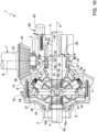
- number 1 indicates a differential group 1 according to the invention housed inside a casing 2 configured to delimit an inner space 3 suited for the purpose.
- the casing 2 further is advantageously configured to house part of the axle shafts 4, 5 of an axle 6, as shown in figure 1 , 5 or 9 .
- the casing 2 can be manufactured as one single piece or in different parts depending on the assembling needs of the differential group 1 and of the axle 6.
- the differential group 1 is operatively interposed between the axle shafts 4, 5 and a drive source 7, such as a transmission shaft configured to convey the torque of an internal combustion engine or an electric motor, which is configured to transmit a torque to the axle shafts 4, 5.
- a drive source 7 such as a transmission shaft configured to convey the torque of an internal combustion engine or an electric motor, which is configured to transmit a torque to the axle shafts 4, 5.
- axle shafts 4, 5, as it is known, are advantageously concentric to one another around a common longitudinal axis A, cooperate - with a respective inner end 4a, 5a - with the differential group 1 and define a wheel hub at outer ends 4b, 5b of theirs.
- the differential group 1 comprises a differential 8 and a transmission 9, the differential 8 being operatively interposed between the axle shafts 4, 5 and the transmission 9 and the latter being operatively interposed between the differential 8 and the drive source 7.
- the differential 8 is of a known type and comprises a carrier 11, which carries a plurality of satellites 13, for example four satellites, which are angularly equally spaced apart from one another by 90° and are supported by a cross-shaped support 14, which is rigidly carried by the carrier 11 and around whose arms the satellites 13 can rotate.
- the satellites rotate on the support 14 around axes contained in a plane, which is perpendicular to the axis A.
- the satellites 13 cooperate with a planetary comprising a left bevel gear 15a and a right bevel gear 16b, respectively, which are rigidly carried by the axle shaft 4 and by the axle shaft 5, respectively, on the respective inner portion.
- the transmission 9 basically comprises a rotating structure 16 and a planetary gear 17, which are operatively interposed between the drive source 7 and the carrier 11.
- the rotating structure 16 is configured to define a closed space 18 suited to house the planetary 17 and the differential 8.
- the rotating structure 16 is coaxial to the axis A of the axle shafts 4, 5 and defines a first and a second opening 16a, 16b, which are configured to allow the inner ends 4a, 5a of the axle shafts 4, 5 to be inserted inside it.
- the rotating structure 16 is supported in a rotary manner by the casing 2 by means of rotary supports 19, such as for example ball bearings.
- the rotating structure 16 is operatively connected to the drive source 7 by means of a toothed gear 21, which is rigidly carried by the rotating structure 16 and is configured to cooperate with the drive source 7 so as to allow a torque to be transmitted.
- the toothed gear 21 is a bevel gear configured to mesh with a respective bevel gear 22 carried by a shaft 23 rotating around an axis B, which is perpendicular to the axis A of the axle shafts 4, 5.
- the rotating structure 16 is manufactured in different portions, in particular a first portion 16' defining the first opening 16a and a second portion 16" defining the second opening 16b.
- the two portions 16', 16'' advantageously are rigidly connected to one another, for example through threaded means.
- the toothed gear 21 is manufactured as a separate piece relative to said portions 16', 16" and is rigidly connected to them.
- the toothed gear 21 is connected, in a clamped manner, between the two portions 16', 16'' and is fixed to them through the same threaded means connecting them.
- the planetary 17 comprises a plurality of satellites 25, which are connected to the carrier 11 of the differential 8, a solar 26, which is housed around one of the axle shafts 4, 5, in the figures the left axle shaft 4, and a crown 27, which is rigidly carried by the rotating structure 16.
- the satellites 25 are free to rotate around a pin 28 rigidly carried by the carrier 11, for example through threaded means, and, hence, cooperate with a toothing 29 defined by the crown 27 and with a toothing 31 defined by the solar 26.
- the pins 28 are arranged in an oblique manner relative to the axes A, B described above, advantageously inclined to define an acute angle ⁇ facing the differential 8.
- the crown 27 is advantageously manufactured as one single piece together with the rotating structure 16 and, advantageously, is manufactured as one single piece together with the first portion 16', in particular it is defined by an axial projection inside the space 18, more preferably close to the opening 16a.
- the solar 26 comprises a sleeve 32, which is housed around the axle shaft 4 and is free to move relative to the latter both in a rotary and in a sliding manner, and a return 33, which is coupled, in its rotation, to the sleeve 32 in an end portion of its.
- the return 33 and the sleeve 32 are coupled to one another in a rotary manner, but are free from a sliding point of view, so that the sleeve 32 can move along the axis A relative to the return 33.
- the return 33 and the sleeve 32 are coupled by means of a grooved coupling 34 obtained by means of a toothing 35 extending in a radial direction from the inside of the return 33 and a toothing 36 extending in a radial direction on the outside of the sleeve 32 in an end portion thereof.
- the sleeve 32 further defines a further shape coupling, which can selectively be engaged with the rotating structure 16.
- it defines a further toothing 37 radially extending from its outer surface and arranged in an intermediate position between the two end portions of the sleeve as well as configured to selectively cooperate, in contact, with a toothing 38 carried by the casing 2.
- the toothing 38 radially extends from the casing 2 towards the axle shaft 4.
- the sleeve 32 further defines a further shape coupling, which can selectively be engaged with the pins 28 supporting the satellites 25.
- it defines a toothing 39, which is obtained on an inner portion of the pins 25 facing the sleeve 32.
- the toothing 36 defining the grooved coupling 34 is sized so as to be able to selectively - and depending on the position of the sleeve 32 along the axis A - mesh with the toothing 39.
- the sleeve 32 is configured to move along the axis A so as to assume a first configuration ( figure 2 ), in which the toothing 36 meshes with the sole toothing 35 of the coupling 34 and, at the same time, the toothing 37 meshes with the toothing 38, thus making the solar 26 integral to the casing 2.
- the sleeve 32 further defines a second configuration ( figure 3 ), in which the toothing 36 meshes with the toothings 35 of the coupling 34 and 39 of the pins 28 and, at the same time, the toothing 37 does not mesh with the respective toothing 38.
- the differential group 1 comprises actuator means 41, which are configured to allow the positioning of the sleeve 32 along the two positions mentioned above to be controlled.
- the actuator means 41 are pneumatic actuator means and comprise a chamber 42, in which a piston 43 is free to slide in a sealing manner.
- the chamber 42 is fluidically connected to a source of air under pressure, so as to be selectively filled with or emptied from said air under pressure.
- the piston 43 is held in a rest position by elastic means 44, which are configured to exert, upon the piston, a force that is contrary to the one exerted by the pressure in the chamber 42 upon the piston 43 itself.
- the latter hence, can slide in a sealing manner in the chamber 42 depending on the force balance between the thrust provided by the elastic means 44 and the pressure of the air in the chamber 42 exerted on it.
- the piston is further connected to the sleeve 32 so that, when there is no air inside the chamber 42, it holds the sleeve 32 in the position of figure 3 , namely a position in which the rotating structure 16 and the solar 26 are free to rotate relative to one another, whereas, when there is air under pressure in the chamber 42, the thrust provided by the elastic means 44 acting upon the piston 43 is overcome, thus causing the latter to move, moving the sleeve 32 to the position of figure 2 , namely a position in which the rotating structure 16 and the solar 26 are coupled to one another in a rotary manner.
- the actuator means 41 are controlled so as to allow air to flow into the chamber 42.
- the force acting upon the piston 43 overcomes the retaining force of the elastic means 44 and pushes the sleeve 32 so that it places itself in the operating condition in which the toothing 35 meshes with the sole toothing 36 and, at the same time, the toothing 37 meshes with the toothing 38.
- the torque coming from the drive source 7 is transmitted from the gearing consisting of the toothed gears 21, 22 to the rotating structure 16, in order to then reach the satellites 25, which rotate between the toothing 31 of the return 33, fixed relative to the casing 2, and the toothing 29 of the crown 27 and transmit said torque to the carrier 11, to which they are rigidly connected.
- the latter splits the torque between the axle shafts 4, 5 in a known manner.
- the actuator means 41 are controlled so as to allow air to flow out of the chamber 42 (if present) or are at rest.
- the retaining force of the elastic means 44 holds the sleeve 32 in the operating condition in which the toothing 35 meshes both with the toothing 36 and with the toothing 39 and, at the same time, the toothing 37 does not mesh with the toothing 38.
- the torque coming from the drive source 7 is transmitted from the gearing consisting of the toothed gears 21, 22 to the rotating structure 16 and, at the same time, to the satellites 25 and to the return 33, which are all connected together to the rotation.
- the satellites 25 directly cause the rotation of the carrier 11 at the rotation velocity of the casing 16.
- the latter splits the torque between the axle shafts 4, 5 in a known manner.
- the rotating structure 16 is coaxial to the axis A of the axle shafts 4, 5 and defines a first and a second opening 16a, 16b, which are configured to allow the inner ends 4a, 5a of the axle shafts 4, 5 to be inserted inside it.
- the rotating structure 16 is operatively connected to the drive source 7 by means of a toothed gear 21, which is rigidly carried by the rotating structure 16 and is configured to cooperate with the drive source 7 so as to allow a torque to be transmitted.
- the toothed gear 21 is a bevel gear configured to mesh with a respective bevel gear 22 carried by a shaft 23 rotating around an axis B, which is perpendicular to the axis A of the axle shafts 4, 5.
- the rotating structure 16 is manufactured in different portions, in particular a first portion 16' defining the first opening 16a and a second portion 16'' defining the second opening 16b.
- the two portions 16', 16'' advantageously are rigidly connected to one another, for example through threaded means.
- the toothed gear 21 is manufactured as a separate piece relative to said portions 16', 16" and is rigidly connected to them.
- the toothed gear 21 is connected, in a clamped manner, between the two portions 16', 16'' and is fixed to them through the same threaded means connecting them.
- the planetary 17 comprises a plurality of satellites 25, which are connected to the carrier 11 of the differential 8, a solar 26, which is housed around one of the axle shafts 4, 5, in the figures the left axle shaft 4, and a crown 27, which is rigidly carried by the rotating structure 16.
- the satellites 25 are free to rotate around a pin 28 rigidly carried by the carrier 11 and, hence, cooperate with a toothing 29 defined by the crown 27 and with a toothing 31 defined by the solar 26.
- the pins 28 are arranged in an oblique manner relative to the axes A, B described above, advantageously inclined to define an acute angle ⁇ facing the opposite side relative to the differential 8.
- the crown 27 is advantageously manufactured as one single piece together with the toothed gear 21, in particular is defined on the opposite side relative to the toothing cooperating with the toothed gear 22.
- the solar 26 advantageously comprises a sleeve 32, which is housed around the axle shaft 4 and is free to move in a rotary manner relative to the latter.
- the sleeve 32 defines a toothing 51 radially extending from an end portion of the sleeve 32 extending towards the differential 8 and configured to mesh with the satellites 25.
- said toothing 51 is a bevel toothing.
- the sleeve 32 also defines a further toothing 52 preferably extending on the remaining portion of the sleeve 32.
- the differential group 1 further comprises a selector 53, which is configured to selectively connect the sleeve 32 to the casing 2 or to the rotating structure 16.
- the selector 53 basically comprises a cylindrical annular element defining an inner toothing 54 facing the sleeve 32 and an outer toothing 55 facing the rotating structure 16.
- the inner toothing 54 is configured to constantly mesh with the toothing 52 and slide along the axis A relative to the sleeve 32, whereas the outer toothing 55 is sized so as to selectively mesh with a respective toothing 56, which is rigidly connected to the casing 2, or with a respective toothing 57, which is rigidly connected to the rotating structure 16.
- the portion of casing 2 shown is very small, for clarity reasons, whereas the toothing 57 is obtained in the first portion of the rotating structure 16', in particular in the area of the first opening 16a.
- the selector 53 is configured to move along the axis A so as to assume a first configuration ( figure 6 ), in which the toothing 55 meshes with the toothing 56 of the casing 2, thus making the solar 26 integral to the latter.
- the selector 53 further defines a second configuration ( figure 7 ), in which the toothing 55 meshes with the toothing 56; in this way, the solar 26 becomes integral to the rotating structure 16.
- the differential group 1 comprises actuator means 41, which are configured to allow the positioning of the sleeve 32 along the two positions mentioned above to be controlled.
- the actuator means 41 are hydraulic actuator means and comprise a hydraulic cylinder 60, for example a double-acting cylinder, which is configured to move a rod 61, which is connected to the selector 53 and is configured to move it between the aforesaid first and second positions.
- a hydraulic cylinder 60 for example a double-acting cylinder, which is configured to move a rod 61, which is connected to the selector 53 and is configured to move it between the aforesaid first and second positions.
- the actuator means 60 are controlled so as to move the rod 61 in such a way that the selector 53 places itself in the operating condition in which the toothing 55 meshes with the toothing 56, thus causing the sleeve 32 to be coupled to the casing 2.
- the torque coming from the drive source 7 is transmitted from the gearing consisting of the toothed gears 21, 22 to the rotating structure 16 and to the satellites 25. They rotate between the toothing 31 of the sleeve 32, which is fixed to the casing 2 and to the toothing 29 of the crown 27, and transmit said torque to the carrier 11, to which they are rigidly connected.
- the latter splits the torque between the axle shafts 4, 5 in a known manner.
- the actuator means 60 are controlled so as to move the rod 61 in such a way that the selector 53 places itself in the operating condition in which the toothing 55 meshes with the toothing 57, thus causing the sleeve 32 to be coupled to the rotating structure 16.
- the torque coming from the drive source 7 is transmitted from the gearing consisting of the toothed gears 21, 22 to the rotating structure 16 and to the satellites 25. They rotate between the toothing 31 of the sleeve 32, which is fixed to the rotating structure 16 and to the toothing 29 of the crown 27, and, hence, transmit said torque from the rotating structure 16 to the carrier 11, to which they are rigidly connected.
- the latter splits the torque between the axle shafts 4, 5 in a known manner.
- condition 8A the torque is transmitted according to a different gear ratio compared to condition 8B, in which the torque transmitted to the carrier 11 is equal to the torque delivered to the rotating structure 16.
- the rotating structure 16 is coaxial to the axis A of the axle shafts 4, 5 and defines a first and a second opening 16a, 16b, which are configured to allow the inner ends 4a, 5a of the axle shafts 4, 5 to be inserted inside it.
- the rotating structure 16 is operatively connected to the drive source 7 by means of a toothed gear 21, which is rigidly carried by the rotating structure 16 and is configured to cooperate with the drive source 7 so as to allow a torque to be transmitted.
- the toothed gear 21 is a bevel gear configured to mesh with a respective bevel gear 22 carried by a shaft 23 rotating around an axis B, which is perpendicular to the axis A of the axle shafts 4, 5.
- the rotating structure 16 is manufactured in different portions, in particular a first portion 16' defining the first opening 16a and a second portion 16'' defining the second opening 16b.
- the two portions 16', 16'' advantageously are rigidly connected to one another, for example through threaded means.
- the toothed gear 21 is manufactured as a separate piece relative to said portions 16', 16" and is rigidly connected to them.
- the toothed gear 21 is fixed to the portions 16', 16'' by means of the same threaded means connecting them, in particular is arranged on the outside of them, in particular facing the second portion 16".
- the planetary 17 comprises a plurality of satellites 25, which are connected to the carrier 11 of the differential 8, a solar 26, which is housed around one of the axle shafts 4, 5, in the figures the right axle shaft 4, and a crown 27, which is rigidly carried by the rotating structure 16.
- the satellites 25 are free to rotate around a pin 28 rigidly carried by the carrier 11 and, hence, cooperate with a toothing 29 defined by the crown 27 and with a toothing 31 defined by the solar 26.
- the pins 28 are arranged in an oblique manner relative to the axes A, B described above, advantageously inclined so as to define an acute angle ⁇ , whose origin substantially coincides with the central point of the differential 8, namely the symmetry axis of the cross-shaped support 14.
- the intersection of the longitudinal axes of the pin 28 substantially coincides with the intersection of the rotation axes of the satellites 13 of the differential 8.
- the pins 28 are manufactured in an integral manner to the carrier 11.
- the crown 27 is advantageously manufactured as one single piece together with one of the portions 16', 16'', in particular with the first portion 16', and basically comprises the toothing 29 axially extending from said portion parallel to the axis A inside the space 18.
- the solar 26 advantageously comprises a sleeve 32, which is housed around the axle shaft 5 and is free to move in a rotary manner relative to the latter.
- the sleeve 32 defines a toothing 51 radially extending from an end portion of the sleeve 32 extending towards the differential 8 and configured to mesh with the satellites 25.
- said toothing 51 is a bevel toothing.
- the sleeve 32 also defines a further toothing 52 preferably extending on the remaining portion of the sleeve 32.
- the differential group 1 further comprises a selector 53, which is configured to selectively connect the sleeve 32 to the casing 2 or to the rotating structure 16.
- the selector 53 basically comprises a cylindrical annular element defining an inner toothing 54 facing the sleeve 32 and an outer toothing 55 facing the rotating structure 16.
- the inner toothing 54 is configured to constantly mesh with the toothing 52 and slide along the axis A relative to the sleeve 32, whereas the outer toothing 55 is sized so as to selectively mesh with a respective toothing 56, which is rigidly connected to the casing 2, or with a respective toothing 57, which is rigidly connected to the rotating structure 16.
- the portion of casing 2 shown is very small, for clarity reasons, whereas the toothing 57 is obtained in the second portion of the rotating structure 16'', in particular in the area of the second opening 16b.
- the selector 53 is configured to move along the axis A so as to assume a first configuration ( figure 11 ), in which the toothing 55 meshes with the toothing 56 of the casing 2, thus making the solar 26 integral to the latter.
- the selector 53 further defines a second configuration ( figure 10 ), in which the toothing 55 meshes with the toothing 56; in this way, the solar 26 becomes integral to the rotating structure 16.
- the differential group 1 comprises actuator means 60, which are configured to allow the positioning of the sleeve 32 along the two positions mentioned above to be controlled.
- the actuator means 60 are electromechanical actuator means and comprise an electric motor 62 configured to operate a worm screw 61 meshing with a threaded ring 63 rigidly carried by the selector 53 and configured to move it along the axis A depending on the rotation of the worm screw 61.
- the actuator means 60 are controlled so as to move the screw 61 in such a way that, by meshing with the ring 62, it moves the selector 53 to the operating condition in which the toothing 55 meshes with the toothing 57, thus causing the sleeve 32 to be coupled to the rotating structure 16.
- the torque coming from the drive source 7 is transmitted from the gearing consisting of the toothed gears 21, 22 to the rotating structure 16 and to the satellites 25. They rotate between the toothing 31 of the sleeve 32, which is fixed to the rotating structure 16 and to the toothing 29 of the crown 27, and, hence, transmit said torque from the rotating structure 16 to the carrier 11, to which they are rigidly connected.
- the latter splits the torque between the axle shafts 4, 5 in a known manner.
- the actuator means 60 are controlled so as to move the screw 61 in such a way that, by meshing with the ring 62, it moves the selector 53 to the operating condition in which the toothing 55 meshes with the toothing 56, thus causing the sleeve 32 to be coupled to the casing 2.
- the torque coming from the drive source 7 is transmitted from the gearing consisting of the toothed gears 21, 22 to the rotating structure 16 and to the satellites 25. They rotate between the toothing 31 of the sleeve 32, which is fixed to the casing 2 and to the toothing 29 of the crown 27, and transmit said torque to the carrier 11, to which they are rigidly connected.
- the differential group 1 further comprises several functional elements, such as anti-dust rings, spacers, o-rings, threaded elements, splines or bearings configured to allow a correct assembly and operation of the structure schematically disclosed above, which are not discussed in the detail for the sake of brevity.
- functional elements such as anti-dust rings, spacers, o-rings, threaded elements, splines or bearings configured to allow a correct assembly and operation of the structure schematically disclosed above, which are not discussed in the detail for the sake of brevity.
- differential locking means can be provided, which are not shown herein.
- the differential group 1 allows for two possible gear ratios between the drive source 7 and the differential 8, thus increasing the versatility of the driving system of the heavy vehicle. In this way, it is possible to provide a versatile differential group for different types of driving styles and loads of the vehicle.
- the differential group 1 is particularly compact thanks to the specific arrangement of the elements that are part of the rotating structure 16 and of the planetary 17.
- all the main gears of the differential group 1 are isolated from the outside, since they are wrapped inside the casing 2 and the rotating structure 16.
- differential group 1 according to the invention can be subjected to changes and variants, which, though, do not go beyond the scope of protection set forth in the appended claim 1.
- actuator means 41, 60, 70 can be different and be used in an equivalent manner as well as in combination in any one of the embodiments described above.
- pairs of toothed gears described above can be of any type and dimension.
- the position of the toothed gear 21, the existence of the selector 53 or the direct actuation of the sleeve 32 by the actuator means can be changed by combining the different embodiments described herein.
- the shape of the structure 2 or of the axle 6 can change depending on the type of vehicle, just like the elements of the differential 8.
Landscapes
- Engineering & Computer Science (AREA)
- General Engineering & Computer Science (AREA)
- Mechanical Engineering (AREA)
- Retarders (AREA)
- Transition And Organic Metals Composition Catalysts For Addition Polymerization (AREA)
- Control Of Motors That Do Not Use Commutators (AREA)
Claims (13)
- Differentialgruppe (1) für ein Schwerlastfahrzeug, welche Differentialgruppe (1) ein Gehäuse (2), welches einen Raum (3) begrenzt, ein Differential (8) und ein Getriebe (9), das in dem Raum (3) aufgenommen ist, umfasst,welches Differential (8) dazu ausgebildet ist, ein Eingangsdrehmoment, das von einer Antriebsquelle (7) auf die Differentialgruppe (1) übertragen wird, in ein Drehmoment von Achswellen (4, 5) des Fahrzeugs aufzuteilen, welche koaxial um eine Achse (A) stehen,wobei das Getriebe (9) operativ zwischen der Antriebsquelle (7) und dem Differential angeordnet ist und eine rotierende Struktur (16) umfasst, die frei drehend von dem Gehäuse (2) und einem Planetengetriebe (17) getragen wird,wobei die rotierende Struktur (16) operativ zwischen der Antriebquelle (7) und dem Planetengetriebe (17) angeordnet ist und einen Raum (18) begrenzt, der das Planetengetriebe (17) und das Differential (8) aufnimmt,wobei das Planetengetriebe (17) umfasst:ein Sonnenrad (26), das drehbar um eine der Achswellen (4, 5) herum angeordnet ist und eine Zahnung (31) festlegt,ein Kronrad (27), das starr durch die rotierende Struktur (16) getragen wird und eine Zahnung (29) festlegt, undeine Mehrzahl von Satellitenrädern (27), die die Zahnung (29, 31) des Sonnenrads (26) und des Kronrads (27) kämmen und dazu ausgebildet sind, um einen Stift (28) zu rotieren, der starr durch einen Träger (11) des Differentials getragen wird,wobei die Differentialgruppe (1) Betätigungsmittel (41, 60, 70) umfasst, dazu ausgebildet, das Sonnenrad (26) derart zu steuern, dass es einen ersten Betriebszustand einnimmt, in welchem es rotierend mit der rotierenden Struktur (16) gekoppelt ist, oder einen zweiten Betriebszustand, in welchem es rotierend mit dem Gehäuse (2) gekoppelt ist, dadurch gekennzeichnet, dass das Sonnenrad (26) eine Hülse (32) umfasst, die durch die Betätigungsmittel (41) zur Bewegung entlang der Achse (A) betätigt wird und um eine der Achswellen (4, 5) herum angeordnet ist,welche Hülse (32) ferner eine erste Zahnung (35) und eine zweite Zahnung (37) festlegt, die jeweils dazu ausgebildet sind, wahlweise die jeweiligen Zähne (39, 38), die von jedem Stift (28) der Satellitenräder (25) und vom Käfig (2) getragen werden, als Funktion der Position der Hülse auf der Achse (A) zu kämmen.
- Differentialgruppe gemäß Anspruch 1, bei welcher das Sonnenrad (26) eine Rückkehreinrichtung (33) umfasst, die die Zahnung (31) festlegt und drehbar mit der Hülse (32) durch eine Nutkupplung gekoppelt ist, die zwischen einer von der Rückkehreinrichtung (33) getragenen Zahnung (36) und der ersten Zahnung (35) der Hülse (32) vorgesehen ist, wobei die erste Zahnung (35) gleichzeitig den Stift (28) und die Zahnung (36) der Rückkehreinrichtung entsprechend der Position der Hülse auf der Achse (A) kämmt.
- Differentialgruppe gemäß Anspruch 1, bei welcher das Sonnenrad (26) eine Hülse (32) umfasst, die die Zahnung (29) festlegt und um eine der Achswellen (4, 5) herum untergebracht ist,sowie eine Auswahleinrichtung (53), die durch die Betätigungsmittel (41) zur Bewegung entlang der Achse (A) betätigt wird und um die Hülse (32) angeordnet und drehbar mit dieser gekoppelt ist,welche Auswahleinrichtung (53) ferner eine Zahnung (55) festlegt, die dazu ausgebildet ist, wahlweise mit den jeweiligen Zahnungen (56, 57) zu kämmen, die durch das Gehäuse (2) und durch die rotierende Struktur (56) getragen werden, derart, dass die Hülse (32) wahlweise eine Einheit mit diesen bildet.
- Differentialgruppe gemäß einem der vorhergehenden Ansprüche, bei welcher die rotierende Struktur (16) eine Zahnung (21) festlegt, dazu ausgebildet, mit der Antriebsquelle (7) zur Übertragung des Drehmoments auf die rotierende Struktur (16) zusammenzuwirken.
- Differentialgruppe gemäß Anspruch 4, bei welcher die rotierende Struktur (16) in zwei Teile (16', 16") ausgebildet ist, wobei die Zahnung (21) auf einem getrennten Element ausgebildet ist und zwischen den zwei Teilen (16', 16") eingeklemmt ist.
- Differentialgruppe gemäß Anspruch 4, bei welcher die rotierende Struktur (16) in zwei Teile (16', 16") ausgebildet ist, und die Zahnung (21) auf einem getrennten Element ausgebildet ist, das an einem der Teile (16') befestigt ist.
- Differentialeinheit gemäß einem der vorhergehenden Ansprüche, bei welcher das Kronrad (27) einstückig mit der rotierenden Struktur (16) ausgebildet ist.
- Differentialgruppe gemäß einem der Ansprüche 4 bis 7, bei welcher das Kronrad (27) einstückig mit der Zahnung (21) ausgebildet ist.
- Differentialgruppe gemäß einem der vorhergehenden Ansprüche, bei welcher eine Längsachse des Stiftes (28) der Satellitenräder (25) schräg zur Achse (A) angeordnet ist.
- Differentialgruppe gemäß Anspruch 9, bei welcher der Schnitt der Längsachsen der Stifte (28) mit dem Schnitt der Drehachsen der Satellitenräder (13) des Differentials (8) zusammenfällt.
- Differentialanordnung gemäß Anspruch 9, bei welcher die Stifte (28) einteilig mit dem Zugträger (11) ausgebildet sind.
- Differentialeinheit gemäß einem der vorhergehenden Ansprüche, bei welcher die Betätigungsmittel (41, 60, 70) zumindest eines der folgenden umfassen: ein pneumatisches Betätigungsmittel, ein hydraulisches Betätigungsmittel, ein mechanisches Betätigungsmittel.
- Fahrzeugachse (6), umfassend eine erste und eine zweite Achswelle (4, 5) und eine Differentialeinheit (1), dazu ausgebildet, die Achswellen (4, 5) mit einer Antriebsquelle (7) des Fahrzeugs zu verbinden, wobei die Differentialanordnung (1) gemäß einem der vorhergehenden Ansprüche ausgebildet ist.
Applications Claiming Priority (2)
| Application Number | Priority Date | Filing Date | Title |
|---|---|---|---|
| IT102020000010891A IT202000010891A1 (it) | 2020-05-13 | 2020-05-13 | Gruppo differenziale a differente velocita' |
| PCT/IB2021/054099 WO2021229491A1 (en) | 2020-05-13 | 2021-05-13 | Differential unit with different velocities |
Publications (2)
| Publication Number | Publication Date |
|---|---|
| EP4150233A1 EP4150233A1 (de) | 2023-03-22 |
| EP4150233B1 true EP4150233B1 (de) | 2024-10-30 |
Family
ID=71784557
Family Applications (1)
| Application Number | Title | Priority Date | Filing Date |
|---|---|---|---|
| EP21730656.2A Active EP4150233B1 (de) | 2020-05-13 | 2021-05-13 | Differentialeinheit mit verschiedenen geschwindigkeiten |
Country Status (4)
| Country | Link |
|---|---|
| EP (1) | EP4150233B1 (de) |
| BR (1) | BR112022023000A2 (de) |
| IT (1) | IT202000010891A1 (de) |
| WO (1) | WO2021229491A1 (de) |
Family Cites Families (5)
| Publication number | Priority date | Publication date | Assignee | Title |
|---|---|---|---|---|
| US2053929A (en) * | 1934-09-20 | 1936-09-08 | Wiedmaier Inc | Power transmission mechanism |
| GB587312A (en) * | 1943-04-29 | 1947-04-22 | Timken Axle Co Detroit | Multi-speed drive axle |
| GB808543A (en) * | 1955-12-16 | 1959-02-04 | Daimler Benz Ag | An axle-driving arrangement for a motor vehicle |
| JP2922476B2 (ja) * | 1997-02-17 | 1999-07-26 | 庄司 井学 | 副キャリヤ盤のない遊星歯車装置 |
| US10857877B2 (en) * | 2016-04-05 | 2020-12-08 | Volvo Construction Equipment Ab | Planet carrier and a planetary gear transmission |
-
2020
- 2020-05-13 IT IT102020000010891A patent/IT202000010891A1/it unknown
-
2021
- 2021-05-13 WO PCT/IB2021/054099 patent/WO2021229491A1/en not_active Ceased
- 2021-05-13 EP EP21730656.2A patent/EP4150233B1/de active Active
- 2021-05-13 BR BR112022023000A patent/BR112022023000A2/pt unknown
Also Published As
| Publication number | Publication date |
|---|---|
| IT202000010891A1 (it) | 2021-11-13 |
| EP4150233A1 (de) | 2023-03-22 |
| WO2021229491A1 (en) | 2021-11-18 |
| BR112022023000A2 (pt) | 2023-01-17 |
Similar Documents
| Publication | Publication Date | Title |
|---|---|---|
| US7211017B2 (en) | Inter-axle differential lock shift mechanism | |
| CN108569085B (zh) | 具有多个离合器套环的车桥组件 | |
| KR830002124B1 (ko) | 자동차 차동기어 장치의 액슬축 단절장치 | |
| JP5511049B2 (ja) | 車軸連結解除アセンブリ | |
| EP3473476B1 (de) | Achsanordnung mit einer untersetzungseinheit und einer zwischenachsdifferenzialeinheit | |
| US4934213A (en) | Power transmission apparatus | |
| WO1981001596A1 (en) | Liquid cooled disc brake for differential of tracked vehicle | |
| US5176591A (en) | Planetary gear differential with disconnect | |
| EP4150233B1 (de) | Differentialeinheit mit verschiedenen geschwindigkeiten | |
| US6248038B1 (en) | Direction reversing transmission gear for vehicle | |
| EP3925811B1 (de) | Radnabe für eine fahrzeugachse mit einem verbesserten integrierten untersetzungssystem | |
| EP4150234B1 (de) | Differentialeinheit mit verschiedenen geschwindigkeiten | |
| EP4149784B1 (de) | Differentialeinheit mit verschiedenen geschwindigkeiten | |
| KR102519195B1 (ko) | 자동차용 슬립 제한형 차동 장치 및 이를 포함하는 전동 구동 장치 | |
| EP4422898B1 (de) | Antriebsanordnung für ein fahrzeug | |
| US11391370B2 (en) | Shift fork actuation assembly | |
| US11320033B2 (en) | Differential assembly for shifting | |
| EP0328300B1 (de) | Differentialkupplung mit Radreaktion | |
| EP3705752B1 (de) | Differentialanordnung mit mehreren geschwindigkeiten | |
| EP3785970A1 (de) | Motoranordnung mit integriertem mehrfachgeschwindigkeitsdifferential | |
| EP4144552A1 (de) | Antriebsanordnung für ein fahrzeug | |
| EP2302246B1 (de) | Drehgetriebekupplung | |
| EP4279765A1 (de) | Radnabe für eine fahrzeugachse mit verbessertem integriertem reduktionssystem | |
| EP4257401A1 (de) | Verbessertes drehmomentverteilungssystem zwischen achsen eines schwerlastfahrzeugs | |
| EP4144554A1 (de) | Antriebsanordnung für ein fahrzeug |
Legal Events
| Date | Code | Title | Description |
|---|---|---|---|
| STAA | Information on the status of an ep patent application or granted ep patent |
Free format text: STATUS: UNKNOWN |
|
| STAA | Information on the status of an ep patent application or granted ep patent |
Free format text: STATUS: THE INTERNATIONAL PUBLICATION HAS BEEN MADE |
|
| PUAI | Public reference made under article 153(3) epc to a published international application that has entered the european phase |
Free format text: ORIGINAL CODE: 0009012 |
|
| STAA | Information on the status of an ep patent application or granted ep patent |
Free format text: STATUS: REQUEST FOR EXAMINATION WAS MADE |
|
| 17P | Request for examination filed |
Effective date: 20221118 |
|
| AK | Designated contracting states |
Kind code of ref document: A1 Designated state(s): AL AT BE BG CH CY CZ DE DK EE ES FI FR GB GR HR HU IE IS IT LI LT LU LV MC MK MT NL NO PL PT RO RS SE SI SK SM TR |
|
| DAV | Request for validation of the european patent (deleted) | ||
| DAX | Request for extension of the european patent (deleted) | ||
| GRAP | Despatch of communication of intention to grant a patent |
Free format text: ORIGINAL CODE: EPIDOSNIGR1 |
|
| STAA | Information on the status of an ep patent application or granted ep patent |
Free format text: STATUS: GRANT OF PATENT IS INTENDED |
|
| INTG | Intention to grant announced |
Effective date: 20240522 |
|
| P01 | Opt-out of the competence of the unified patent court (upc) registered |
Effective date: 20240523 |
|
| GRAS | Grant fee paid |
Free format text: ORIGINAL CODE: EPIDOSNIGR3 |
|
| GRAA | (expected) grant |
Free format text: ORIGINAL CODE: 0009210 |
|
| STAA | Information on the status of an ep patent application or granted ep patent |
Free format text: STATUS: THE PATENT HAS BEEN GRANTED |
|
| AK | Designated contracting states |
Kind code of ref document: B1 Designated state(s): AL AT BE BG CH CY CZ DE DK EE ES FI FR GB GR HR HU IE IS IT LI LT LU LV MC MK MT NL NO PL PT RO RS SE SI SK SM TR |
|
| REG | Reference to a national code |
Ref country code: GB Ref legal event code: FG4D |
|
| REG | Reference to a national code |
Ref country code: CH Ref legal event code: EP |
|
| REG | Reference to a national code |
Ref country code: IE Ref legal event code: FG4D |
|
| REG | Reference to a national code |
Ref country code: DE Ref legal event code: R096 Ref document number: 602021021020 Country of ref document: DE |
|
| REG | Reference to a national code |
Ref country code: LT Ref legal event code: MG9D |
|
| REG | Reference to a national code |
Ref country code: NL Ref legal event code: MP Effective date: 20241030 |
|
| PG25 | Lapsed in a contracting state [announced via postgrant information from national office to epo] |
Ref country code: PT Free format text: LAPSE BECAUSE OF FAILURE TO SUBMIT A TRANSLATION OF THE DESCRIPTION OR TO PAY THE FEE WITHIN THE PRESCRIBED TIME-LIMIT Effective date: 20250228 Ref country code: IS Free format text: LAPSE BECAUSE OF FAILURE TO SUBMIT A TRANSLATION OF THE DESCRIPTION OR TO PAY THE FEE WITHIN THE PRESCRIBED TIME-LIMIT Effective date: 20250228 Ref country code: HR Free format text: LAPSE BECAUSE OF FAILURE TO SUBMIT A TRANSLATION OF THE DESCRIPTION OR TO PAY THE FEE WITHIN THE PRESCRIBED TIME-LIMIT Effective date: 20241030 |
|
| PG25 | Lapsed in a contracting state [announced via postgrant information from national office to epo] |
Ref country code: FI Free format text: LAPSE BECAUSE OF FAILURE TO SUBMIT A TRANSLATION OF THE DESCRIPTION OR TO PAY THE FEE WITHIN THE PRESCRIBED TIME-LIMIT Effective date: 20241030 Ref country code: NL Free format text: LAPSE BECAUSE OF FAILURE TO SUBMIT A TRANSLATION OF THE DESCRIPTION OR TO PAY THE FEE WITHIN THE PRESCRIBED TIME-LIMIT Effective date: 20241030 |
|
| REG | Reference to a national code |
Ref country code: AT Ref legal event code: MK05 Ref document number: 1737153 Country of ref document: AT Kind code of ref document: T Effective date: 20241030 |
|
| PG25 | Lapsed in a contracting state [announced via postgrant information from national office to epo] |
Ref country code: BG Free format text: LAPSE BECAUSE OF FAILURE TO SUBMIT A TRANSLATION OF THE DESCRIPTION OR TO PAY THE FEE WITHIN THE PRESCRIBED TIME-LIMIT Effective date: 20241030 |
|
| PG25 | Lapsed in a contracting state [announced via postgrant information from national office to epo] |
Ref country code: ES Free format text: LAPSE BECAUSE OF FAILURE TO SUBMIT A TRANSLATION OF THE DESCRIPTION OR TO PAY THE FEE WITHIN THE PRESCRIBED TIME-LIMIT Effective date: 20241030 |
|
| PG25 | Lapsed in a contracting state [announced via postgrant information from national office to epo] |
Ref country code: NO Free format text: LAPSE BECAUSE OF FAILURE TO SUBMIT A TRANSLATION OF THE DESCRIPTION OR TO PAY THE FEE WITHIN THE PRESCRIBED TIME-LIMIT Effective date: 20250130 |
|
| PG25 | Lapsed in a contracting state [announced via postgrant information from national office to epo] |
Ref country code: LV Free format text: LAPSE BECAUSE OF FAILURE TO SUBMIT A TRANSLATION OF THE DESCRIPTION OR TO PAY THE FEE WITHIN THE PRESCRIBED TIME-LIMIT Effective date: 20241030 Ref country code: GR Free format text: LAPSE BECAUSE OF FAILURE TO SUBMIT A TRANSLATION OF THE DESCRIPTION OR TO PAY THE FEE WITHIN THE PRESCRIBED TIME-LIMIT Effective date: 20250131 Ref country code: AT Free format text: LAPSE BECAUSE OF FAILURE TO SUBMIT A TRANSLATION OF THE DESCRIPTION OR TO PAY THE FEE WITHIN THE PRESCRIBED TIME-LIMIT Effective date: 20241030 |
|
| PG25 | Lapsed in a contracting state [announced via postgrant information from national office to epo] |
Ref country code: PL Free format text: LAPSE BECAUSE OF FAILURE TO SUBMIT A TRANSLATION OF THE DESCRIPTION OR TO PAY THE FEE WITHIN THE PRESCRIBED TIME-LIMIT Effective date: 20241030 |
|
| PG25 | Lapsed in a contracting state [announced via postgrant information from national office to epo] |
Ref country code: RS Free format text: LAPSE BECAUSE OF FAILURE TO SUBMIT A TRANSLATION OF THE DESCRIPTION OR TO PAY THE FEE WITHIN THE PRESCRIBED TIME-LIMIT Effective date: 20250130 |
|
| PG25 | Lapsed in a contracting state [announced via postgrant information from national office to epo] |
Ref country code: SM Free format text: LAPSE BECAUSE OF FAILURE TO SUBMIT A TRANSLATION OF THE DESCRIPTION OR TO PAY THE FEE WITHIN THE PRESCRIBED TIME-LIMIT Effective date: 20241030 |
|
| PGFP | Annual fee paid to national office [announced via postgrant information from national office to epo] |
Ref country code: DE Payment date: 20250528 Year of fee payment: 5 |
|
| PG25 | Lapsed in a contracting state [announced via postgrant information from national office to epo] |
Ref country code: DK Free format text: LAPSE BECAUSE OF FAILURE TO SUBMIT A TRANSLATION OF THE DESCRIPTION OR TO PAY THE FEE WITHIN THE PRESCRIBED TIME-LIMIT Effective date: 20241030 |
|
| PGFP | Annual fee paid to national office [announced via postgrant information from national office to epo] |
Ref country code: IT Payment date: 20250512 Year of fee payment: 5 |
|
| PG25 | Lapsed in a contracting state [announced via postgrant information from national office to epo] |
Ref country code: EE Free format text: LAPSE BECAUSE OF FAILURE TO SUBMIT A TRANSLATION OF THE DESCRIPTION OR TO PAY THE FEE WITHIN THE PRESCRIBED TIME-LIMIT Effective date: 20241030 |
|
| PGFP | Annual fee paid to national office [announced via postgrant information from national office to epo] |
Ref country code: FR Payment date: 20250526 Year of fee payment: 5 |
|
| PG25 | Lapsed in a contracting state [announced via postgrant information from national office to epo] |
Ref country code: RO Free format text: LAPSE BECAUSE OF FAILURE TO SUBMIT A TRANSLATION OF THE DESCRIPTION OR TO PAY THE FEE WITHIN THE PRESCRIBED TIME-LIMIT Effective date: 20241030 |
|
| PG25 | Lapsed in a contracting state [announced via postgrant information from national office to epo] |
Ref country code: SK Free format text: LAPSE BECAUSE OF FAILURE TO SUBMIT A TRANSLATION OF THE DESCRIPTION OR TO PAY THE FEE WITHIN THE PRESCRIBED TIME-LIMIT Effective date: 20241030 |
|
| PG25 | Lapsed in a contracting state [announced via postgrant information from national office to epo] |
Ref country code: CZ Free format text: LAPSE BECAUSE OF FAILURE TO SUBMIT A TRANSLATION OF THE DESCRIPTION OR TO PAY THE FEE WITHIN THE PRESCRIBED TIME-LIMIT Effective date: 20241030 |
|
| REG | Reference to a national code |
Ref country code: DE Ref legal event code: R097 Ref document number: 602021021020 Country of ref document: DE |
|
| PLBE | No opposition filed within time limit |
Free format text: ORIGINAL CODE: 0009261 |
|
| STAA | Information on the status of an ep patent application or granted ep patent |
Free format text: STATUS: NO OPPOSITION FILED WITHIN TIME LIMIT |
|
| PG25 | Lapsed in a contracting state [announced via postgrant information from national office to epo] |
Ref country code: SE Free format text: LAPSE BECAUSE OF FAILURE TO SUBMIT A TRANSLATION OF THE DESCRIPTION OR TO PAY THE FEE WITHIN THE PRESCRIBED TIME-LIMIT Effective date: 20241030 |
|
| 26N | No opposition filed |
Effective date: 20250731 |
|
| REG | Reference to a national code |
Ref country code: CH Ref legal event code: H13 Free format text: ST27 STATUS EVENT CODE: U-0-0-H10-H13 (AS PROVIDED BY THE NATIONAL OFFICE) Effective date: 20251223 |
|
| PG25 | Lapsed in a contracting state [announced via postgrant information from national office to epo] |
Ref country code: LU Free format text: LAPSE BECAUSE OF NON-PAYMENT OF DUE FEES Effective date: 20250513 |
|
| PG25 | Lapsed in a contracting state [announced via postgrant information from national office to epo] |
Ref country code: CH Free format text: LAPSE BECAUSE OF NON-PAYMENT OF DUE FEES Effective date: 20250531 |
|
| GBPC | Gb: european patent ceased through non-payment of renewal fee |
Effective date: 20250513 |
|
| PG25 | Lapsed in a contracting state [announced via postgrant information from national office to epo] |
Ref country code: MC Free format text: LAPSE BECAUSE OF FAILURE TO SUBMIT A TRANSLATION OF THE DESCRIPTION OR TO PAY THE FEE WITHIN THE PRESCRIBED TIME-LIMIT Effective date: 20241030 |