EP4150233B1 - Differential unit with different velocities - Google Patents
Differential unit with different velocities Download PDFInfo
- Publication number
- EP4150233B1 EP4150233B1 EP21730656.2A EP21730656A EP4150233B1 EP 4150233 B1 EP4150233 B1 EP 4150233B1 EP 21730656 A EP21730656 A EP 21730656A EP 4150233 B1 EP4150233 B1 EP 4150233B1
- Authority
- EP
- European Patent Office
- Prior art keywords
- toothing
- differential
- rotating structure
- sleeve
- differential group
- Prior art date
- Legal status (The legal status is an assumption and is not a legal conclusion. Google has not performed a legal analysis and makes no representation as to the accuracy of the status listed.)
- Active
Links
Images


Classifications
-
- F—MECHANICAL ENGINEERING; LIGHTING; HEATING; WEAPONS; BLASTING
- F16—ENGINEERING ELEMENTS AND UNITS; GENERAL MEASURES FOR PRODUCING AND MAINTAINING EFFECTIVE FUNCTIONING OF MACHINES OR INSTALLATIONS; THERMAL INSULATION IN GENERAL
- F16H—GEARING
- F16H37/00—Combinations of mechanical gearings, not provided for in groups F16H1/00 - F16H35/00
- F16H37/02—Combinations of mechanical gearings, not provided for in groups F16H1/00 - F16H35/00 comprising essentially only toothed or friction gearings
- F16H37/06—Combinations of mechanical gearings, not provided for in groups F16H1/00 - F16H35/00 comprising essentially only toothed or friction gearings with a plurality of driving or driven shafts; with arrangements for dividing torque between two or more intermediate shafts
- F16H37/08—Combinations of mechanical gearings, not provided for in groups F16H1/00 - F16H35/00 comprising essentially only toothed or friction gearings with a plurality of driving or driven shafts; with arrangements for dividing torque between two or more intermediate shafts with differential gearing
- F16H37/0806—Combinations of mechanical gearings, not provided for in groups F16H1/00 - F16H35/00 comprising essentially only toothed or friction gearings with a plurality of driving or driven shafts; with arrangements for dividing torque between two or more intermediate shafts with differential gearing with a plurality of driving or driven shafts
- F16H37/0813—Combinations of mechanical gearings, not provided for in groups F16H1/00 - F16H35/00 comprising essentially only toothed or friction gearings with a plurality of driving or driven shafts; with arrangements for dividing torque between two or more intermediate shafts with differential gearing with a plurality of driving or driven shafts with only one input shaft
-
- B—PERFORMING OPERATIONS; TRANSPORTING
- B60—VEHICLES IN GENERAL
- B60K—ARRANGEMENT OR MOUNTING OF PROPULSION UNITS OR OF TRANSMISSIONS IN VEHICLES; ARRANGEMENT OR MOUNTING OF PLURAL DIVERSE PRIME-MOVERS IN VEHICLES; AUXILIARY DRIVES FOR VEHICLES; INSTRUMENTATION OR DASHBOARDS FOR VEHICLES; ARRANGEMENTS IN CONNECTION WITH COOLING, AIR INTAKE, GAS EXHAUST OR FUEL SUPPLY OF PROPULSION UNITS IN VEHICLES
- B60K17/00—Arrangement or mounting of transmissions in vehicles
- B60K17/04—Arrangement or mounting of transmissions in vehicles characterised by arrangement, location or kind of gearing
- B60K17/16—Arrangement or mounting of transmissions in vehicles characterised by arrangement, location or kind of gearing of differential gearing
- B60K17/165—Arrangement or mounting of transmissions in vehicles characterised by arrangement, location or kind of gearing of differential gearing provided between independent half axles
-
- F—MECHANICAL ENGINEERING; LIGHTING; HEATING; WEAPONS; BLASTING
- F16—ENGINEERING ELEMENTS AND UNITS; GENERAL MEASURES FOR PRODUCING AND MAINTAINING EFFECTIVE FUNCTIONING OF MACHINES OR INSTALLATIONS; THERMAL INSULATION IN GENERAL
- F16H—GEARING
- F16H63/00—Control outputs from the control unit to change-speed- or reversing-gearings for conveying rotary motion or to other devices than the final output mechanism
- F16H63/02—Final output mechanisms therefor; Actuating means for the final output mechanisms
- F16H63/30—Constructional features of the final output mechanisms
- F16H63/304—Constructional features of the final output mechanisms the final output mechanisms comprising elements moved by electrical or magnetic force
- F16H2063/3063—Constructional features of the final output mechanisms the final output mechanisms comprising elements moved by electrical or magnetic force using screw devices
-
- F—MECHANICAL ENGINEERING; LIGHTING; HEATING; WEAPONS; BLASTING
- F16—ENGINEERING ELEMENTS AND UNITS; GENERAL MEASURES FOR PRODUCING AND MAINTAINING EFFECTIVE FUNCTIONING OF MACHINES OR INSTALLATIONS; THERMAL INSULATION IN GENERAL
- F16H—GEARING
- F16H63/00—Control outputs from the control unit to change-speed- or reversing-gearings for conveying rotary motion or to other devices than the final output mechanism
- F16H63/02—Final output mechanisms therefor; Actuating means for the final output mechanisms
- F16H63/30—Constructional features of the final output mechanisms
- F16H2063/3093—Final output elements, i.e. the final elements to establish gear ratio, e.g. coupling sleeves or other means establishing coupling to shaft
-
- F—MECHANICAL ENGINEERING; LIGHTING; HEATING; WEAPONS; BLASTING
- F16—ENGINEERING ELEMENTS AND UNITS; GENERAL MEASURES FOR PRODUCING AND MAINTAINING EFFECTIVE FUNCTIONING OF MACHINES OR INSTALLATIONS; THERMAL INSULATION IN GENERAL
- F16H—GEARING
- F16H2200/00—Transmissions for multiple ratios
- F16H2200/003—Transmissions for multiple ratios characterised by the number of forward speeds
- F16H2200/0034—Transmissions for multiple ratios characterised by the number of forward speeds the gear ratios comprising two forward speeds
-
- F—MECHANICAL ENGINEERING; LIGHTING; HEATING; WEAPONS; BLASTING
- F16—ENGINEERING ELEMENTS AND UNITS; GENERAL MEASURES FOR PRODUCING AND MAINTAINING EFFECTIVE FUNCTIONING OF MACHINES OR INSTALLATIONS; THERMAL INSULATION IN GENERAL
- F16H—GEARING
- F16H2200/00—Transmissions for multiple ratios
- F16H2200/20—Transmissions using gears with orbital motion
- F16H2200/2002—Transmissions using gears with orbital motion characterised by the number of sets of orbital gears
- F16H2200/2005—Transmissions using gears with orbital motion characterised by the number of sets of orbital gears with one sets of orbital gears
-
- F—MECHANICAL ENGINEERING; LIGHTING; HEATING; WEAPONS; BLASTING
- F16—ENGINEERING ELEMENTS AND UNITS; GENERAL MEASURES FOR PRODUCING AND MAINTAINING EFFECTIVE FUNCTIONING OF MACHINES OR INSTALLATIONS; THERMAL INSULATION IN GENERAL
- F16H—GEARING
- F16H2200/00—Transmissions for multiple ratios
- F16H2200/20—Transmissions using gears with orbital motion
- F16H2200/203—Transmissions using gears with orbital motion characterised by the engaging friction means not of the freewheel type, e.g. friction clutches or brakes
- F16H2200/2035—Transmissions using gears with orbital motion characterised by the engaging friction means not of the freewheel type, e.g. friction clutches or brakes with two engaging means
-
- F—MECHANICAL ENGINEERING; LIGHTING; HEATING; WEAPONS; BLASTING
- F16—ENGINEERING ELEMENTS AND UNITS; GENERAL MEASURES FOR PRODUCING AND MAINTAINING EFFECTIVE FUNCTIONING OF MACHINES OR INSTALLATIONS; THERMAL INSULATION IN GENERAL
- F16H—GEARING
- F16H3/00—Toothed gearings for conveying rotary motion with variable gear ratio or for reversing rotary motion
- F16H3/44—Toothed gearings for conveying rotary motion with variable gear ratio or for reversing rotary motion using gears having orbital motion
- F16H3/46—Gearings having only two central gears, connected by orbital gears
- F16H3/48—Gearings having only two central gears, connected by orbital gears with single orbital gears or pairs of rigidly-connected orbital gears
- F16H3/50—Gearings having only two central gears, connected by orbital gears with single orbital gears or pairs of rigidly-connected orbital gears comprising orbital conical gears
-
- F—MECHANICAL ENGINEERING; LIGHTING; HEATING; WEAPONS; BLASTING
- F16—ENGINEERING ELEMENTS AND UNITS; GENERAL MEASURES FOR PRODUCING AND MAINTAINING EFFECTIVE FUNCTIONING OF MACHINES OR INSTALLATIONS; THERMAL INSULATION IN GENERAL
- F16H—GEARING
- F16H48/00—Differential gearings
- F16H48/06—Differential gearings with gears having orbital motion
- F16H48/08—Differential gearings with gears having orbital motion comprising bevel gears
-
- F—MECHANICAL ENGINEERING; LIGHTING; HEATING; WEAPONS; BLASTING
- F16—ENGINEERING ELEMENTS AND UNITS; GENERAL MEASURES FOR PRODUCING AND MAINTAINING EFFECTIVE FUNCTIONING OF MACHINES OR INSTALLATIONS; THERMAL INSULATION IN GENERAL
- F16H—GEARING
- F16H63/00—Control outputs from the control unit to change-speed- or reversing-gearings for conveying rotary motion or to other devices than the final output mechanism
- F16H63/02—Final output mechanisms therefor; Actuating means for the final output mechanisms
- F16H63/30—Constructional features of the final output mechanisms
- F16H63/3023—Constructional features of the final output mechanisms the final output mechanisms comprising elements moved by fluid pressure
Definitions
- the invention relates to a differential unit, more in particular to a differential group for a heavy vehicle, such as a truck.
- the differential is a power transmission member available in vehicles to distribute the torque coming from an input shaft to a pair of output shafts connected to respective wheels.
- the differential allows different velocities to be delivered to the wheels, so as to allow each one of them to follow the relative trajectory during paths covering a bend or paths with different grips.
- a differential comprises a carrier, to which two shafts are constrained, and two satellites, which are placed on the shafts and mesh with two driven planetary gears, which are integral to the axle shafts, each connected to the respective wheel.
- Known differentials are also provided with a locking function, which is configured to cause the two axle shafts to be integral to one another. This function is useful in case of a surface allowing for a reduced grip of the tyres, in which case one of the two wheels, if it were not constrained to the other one, would tend to skid, thus dispersing the torque.
- the object of the invention is to fulfil the needs discussed above in an economic fashion.
- number 1 indicates a differential group 1 according to the invention housed inside a casing 2 configured to delimit an inner space 3 suited for the purpose.
- the casing 2 further is advantageously configured to house part of the axle shafts 4, 5 of an axle 6, as shown in figure 1 , 5 or 9 .
- the casing 2 can be manufactured as one single piece or in different parts depending on the assembling needs of the differential group 1 and of the axle 6.
- the differential group 1 is operatively interposed between the axle shafts 4, 5 and a drive source 7, such as a transmission shaft configured to convey the torque of an internal combustion engine or an electric motor, which is configured to transmit a torque to the axle shafts 4, 5.
- a drive source 7 such as a transmission shaft configured to convey the torque of an internal combustion engine or an electric motor, which is configured to transmit a torque to the axle shafts 4, 5.
- axle shafts 4, 5, as it is known, are advantageously concentric to one another around a common longitudinal axis A, cooperate - with a respective inner end 4a, 5a - with the differential group 1 and define a wheel hub at outer ends 4b, 5b of theirs.
- the differential group 1 comprises a differential 8 and a transmission 9, the differential 8 being operatively interposed between the axle shafts 4, 5 and the transmission 9 and the latter being operatively interposed between the differential 8 and the drive source 7.
- the differential 8 is of a known type and comprises a carrier 11, which carries a plurality of satellites 13, for example four satellites, which are angularly equally spaced apart from one another by 90° and are supported by a cross-shaped support 14, which is rigidly carried by the carrier 11 and around whose arms the satellites 13 can rotate.
- the satellites rotate on the support 14 around axes contained in a plane, which is perpendicular to the axis A.
- the satellites 13 cooperate with a planetary comprising a left bevel gear 15a and a right bevel gear 16b, respectively, which are rigidly carried by the axle shaft 4 and by the axle shaft 5, respectively, on the respective inner portion.
- the transmission 9 basically comprises a rotating structure 16 and a planetary gear 17, which are operatively interposed between the drive source 7 and the carrier 11.
- the rotating structure 16 is configured to define a closed space 18 suited to house the planetary 17 and the differential 8.
- the rotating structure 16 is coaxial to the axis A of the axle shafts 4, 5 and defines a first and a second opening 16a, 16b, which are configured to allow the inner ends 4a, 5a of the axle shafts 4, 5 to be inserted inside it.
- the rotating structure 16 is supported in a rotary manner by the casing 2 by means of rotary supports 19, such as for example ball bearings.
- the rotating structure 16 is operatively connected to the drive source 7 by means of a toothed gear 21, which is rigidly carried by the rotating structure 16 and is configured to cooperate with the drive source 7 so as to allow a torque to be transmitted.
- the toothed gear 21 is a bevel gear configured to mesh with a respective bevel gear 22 carried by a shaft 23 rotating around an axis B, which is perpendicular to the axis A of the axle shafts 4, 5.
- the rotating structure 16 is manufactured in different portions, in particular a first portion 16' defining the first opening 16a and a second portion 16" defining the second opening 16b.
- the two portions 16', 16'' advantageously are rigidly connected to one another, for example through threaded means.
- the toothed gear 21 is manufactured as a separate piece relative to said portions 16', 16" and is rigidly connected to them.
- the toothed gear 21 is connected, in a clamped manner, between the two portions 16', 16'' and is fixed to them through the same threaded means connecting them.
- the planetary 17 comprises a plurality of satellites 25, which are connected to the carrier 11 of the differential 8, a solar 26, which is housed around one of the axle shafts 4, 5, in the figures the left axle shaft 4, and a crown 27, which is rigidly carried by the rotating structure 16.
- the satellites 25 are free to rotate around a pin 28 rigidly carried by the carrier 11, for example through threaded means, and, hence, cooperate with a toothing 29 defined by the crown 27 and with a toothing 31 defined by the solar 26.
- the pins 28 are arranged in an oblique manner relative to the axes A, B described above, advantageously inclined to define an acute angle ⁇ facing the differential 8.
- the crown 27 is advantageously manufactured as one single piece together with the rotating structure 16 and, advantageously, is manufactured as one single piece together with the first portion 16', in particular it is defined by an axial projection inside the space 18, more preferably close to the opening 16a.
- the solar 26 comprises a sleeve 32, which is housed around the axle shaft 4 and is free to move relative to the latter both in a rotary and in a sliding manner, and a return 33, which is coupled, in its rotation, to the sleeve 32 in an end portion of its.
- the return 33 and the sleeve 32 are coupled to one another in a rotary manner, but are free from a sliding point of view, so that the sleeve 32 can move along the axis A relative to the return 33.
- the return 33 and the sleeve 32 are coupled by means of a grooved coupling 34 obtained by means of a toothing 35 extending in a radial direction from the inside of the return 33 and a toothing 36 extending in a radial direction on the outside of the sleeve 32 in an end portion thereof.
- the sleeve 32 further defines a further shape coupling, which can selectively be engaged with the rotating structure 16.
- it defines a further toothing 37 radially extending from its outer surface and arranged in an intermediate position between the two end portions of the sleeve as well as configured to selectively cooperate, in contact, with a toothing 38 carried by the casing 2.
- the toothing 38 radially extends from the casing 2 towards the axle shaft 4.
- the sleeve 32 further defines a further shape coupling, which can selectively be engaged with the pins 28 supporting the satellites 25.
- it defines a toothing 39, which is obtained on an inner portion of the pins 25 facing the sleeve 32.
- the toothing 36 defining the grooved coupling 34 is sized so as to be able to selectively - and depending on the position of the sleeve 32 along the axis A - mesh with the toothing 39.
- the sleeve 32 is configured to move along the axis A so as to assume a first configuration ( figure 2 ), in which the toothing 36 meshes with the sole toothing 35 of the coupling 34 and, at the same time, the toothing 37 meshes with the toothing 38, thus making the solar 26 integral to the casing 2.
- the sleeve 32 further defines a second configuration ( figure 3 ), in which the toothing 36 meshes with the toothings 35 of the coupling 34 and 39 of the pins 28 and, at the same time, the toothing 37 does not mesh with the respective toothing 38.
- the differential group 1 comprises actuator means 41, which are configured to allow the positioning of the sleeve 32 along the two positions mentioned above to be controlled.
- the actuator means 41 are pneumatic actuator means and comprise a chamber 42, in which a piston 43 is free to slide in a sealing manner.
- the chamber 42 is fluidically connected to a source of air under pressure, so as to be selectively filled with or emptied from said air under pressure.
- the piston 43 is held in a rest position by elastic means 44, which are configured to exert, upon the piston, a force that is contrary to the one exerted by the pressure in the chamber 42 upon the piston 43 itself.
- the latter hence, can slide in a sealing manner in the chamber 42 depending on the force balance between the thrust provided by the elastic means 44 and the pressure of the air in the chamber 42 exerted on it.
- the piston is further connected to the sleeve 32 so that, when there is no air inside the chamber 42, it holds the sleeve 32 in the position of figure 3 , namely a position in which the rotating structure 16 and the solar 26 are free to rotate relative to one another, whereas, when there is air under pressure in the chamber 42, the thrust provided by the elastic means 44 acting upon the piston 43 is overcome, thus causing the latter to move, moving the sleeve 32 to the position of figure 2 , namely a position in which the rotating structure 16 and the solar 26 are coupled to one another in a rotary manner.
- the actuator means 41 are controlled so as to allow air to flow into the chamber 42.
- the force acting upon the piston 43 overcomes the retaining force of the elastic means 44 and pushes the sleeve 32 so that it places itself in the operating condition in which the toothing 35 meshes with the sole toothing 36 and, at the same time, the toothing 37 meshes with the toothing 38.
- the torque coming from the drive source 7 is transmitted from the gearing consisting of the toothed gears 21, 22 to the rotating structure 16, in order to then reach the satellites 25, which rotate between the toothing 31 of the return 33, fixed relative to the casing 2, and the toothing 29 of the crown 27 and transmit said torque to the carrier 11, to which they are rigidly connected.
- the latter splits the torque between the axle shafts 4, 5 in a known manner.
- the actuator means 41 are controlled so as to allow air to flow out of the chamber 42 (if present) or are at rest.
- the retaining force of the elastic means 44 holds the sleeve 32 in the operating condition in which the toothing 35 meshes both with the toothing 36 and with the toothing 39 and, at the same time, the toothing 37 does not mesh with the toothing 38.
- the torque coming from the drive source 7 is transmitted from the gearing consisting of the toothed gears 21, 22 to the rotating structure 16 and, at the same time, to the satellites 25 and to the return 33, which are all connected together to the rotation.
- the satellites 25 directly cause the rotation of the carrier 11 at the rotation velocity of the casing 16.
- the latter splits the torque between the axle shafts 4, 5 in a known manner.
- the rotating structure 16 is coaxial to the axis A of the axle shafts 4, 5 and defines a first and a second opening 16a, 16b, which are configured to allow the inner ends 4a, 5a of the axle shafts 4, 5 to be inserted inside it.
- the rotating structure 16 is operatively connected to the drive source 7 by means of a toothed gear 21, which is rigidly carried by the rotating structure 16 and is configured to cooperate with the drive source 7 so as to allow a torque to be transmitted.
- the toothed gear 21 is a bevel gear configured to mesh with a respective bevel gear 22 carried by a shaft 23 rotating around an axis B, which is perpendicular to the axis A of the axle shafts 4, 5.
- the rotating structure 16 is manufactured in different portions, in particular a first portion 16' defining the first opening 16a and a second portion 16'' defining the second opening 16b.
- the two portions 16', 16'' advantageously are rigidly connected to one another, for example through threaded means.
- the toothed gear 21 is manufactured as a separate piece relative to said portions 16', 16" and is rigidly connected to them.
- the toothed gear 21 is connected, in a clamped manner, between the two portions 16', 16'' and is fixed to them through the same threaded means connecting them.
- the planetary 17 comprises a plurality of satellites 25, which are connected to the carrier 11 of the differential 8, a solar 26, which is housed around one of the axle shafts 4, 5, in the figures the left axle shaft 4, and a crown 27, which is rigidly carried by the rotating structure 16.
- the satellites 25 are free to rotate around a pin 28 rigidly carried by the carrier 11 and, hence, cooperate with a toothing 29 defined by the crown 27 and with a toothing 31 defined by the solar 26.
- the pins 28 are arranged in an oblique manner relative to the axes A, B described above, advantageously inclined to define an acute angle ⁇ facing the opposite side relative to the differential 8.
- the crown 27 is advantageously manufactured as one single piece together with the toothed gear 21, in particular is defined on the opposite side relative to the toothing cooperating with the toothed gear 22.
- the solar 26 advantageously comprises a sleeve 32, which is housed around the axle shaft 4 and is free to move in a rotary manner relative to the latter.
- the sleeve 32 defines a toothing 51 radially extending from an end portion of the sleeve 32 extending towards the differential 8 and configured to mesh with the satellites 25.
- said toothing 51 is a bevel toothing.
- the sleeve 32 also defines a further toothing 52 preferably extending on the remaining portion of the sleeve 32.
- the differential group 1 further comprises a selector 53, which is configured to selectively connect the sleeve 32 to the casing 2 or to the rotating structure 16.
- the selector 53 basically comprises a cylindrical annular element defining an inner toothing 54 facing the sleeve 32 and an outer toothing 55 facing the rotating structure 16.
- the inner toothing 54 is configured to constantly mesh with the toothing 52 and slide along the axis A relative to the sleeve 32, whereas the outer toothing 55 is sized so as to selectively mesh with a respective toothing 56, which is rigidly connected to the casing 2, or with a respective toothing 57, which is rigidly connected to the rotating structure 16.
- the portion of casing 2 shown is very small, for clarity reasons, whereas the toothing 57 is obtained in the first portion of the rotating structure 16', in particular in the area of the first opening 16a.
- the selector 53 is configured to move along the axis A so as to assume a first configuration ( figure 6 ), in which the toothing 55 meshes with the toothing 56 of the casing 2, thus making the solar 26 integral to the latter.
- the selector 53 further defines a second configuration ( figure 7 ), in which the toothing 55 meshes with the toothing 56; in this way, the solar 26 becomes integral to the rotating structure 16.
- the differential group 1 comprises actuator means 41, which are configured to allow the positioning of the sleeve 32 along the two positions mentioned above to be controlled.
- the actuator means 41 are hydraulic actuator means and comprise a hydraulic cylinder 60, for example a double-acting cylinder, which is configured to move a rod 61, which is connected to the selector 53 and is configured to move it between the aforesaid first and second positions.
- a hydraulic cylinder 60 for example a double-acting cylinder, which is configured to move a rod 61, which is connected to the selector 53 and is configured to move it between the aforesaid first and second positions.
- the actuator means 60 are controlled so as to move the rod 61 in such a way that the selector 53 places itself in the operating condition in which the toothing 55 meshes with the toothing 56, thus causing the sleeve 32 to be coupled to the casing 2.
- the torque coming from the drive source 7 is transmitted from the gearing consisting of the toothed gears 21, 22 to the rotating structure 16 and to the satellites 25. They rotate between the toothing 31 of the sleeve 32, which is fixed to the casing 2 and to the toothing 29 of the crown 27, and transmit said torque to the carrier 11, to which they are rigidly connected.
- the latter splits the torque between the axle shafts 4, 5 in a known manner.
- the actuator means 60 are controlled so as to move the rod 61 in such a way that the selector 53 places itself in the operating condition in which the toothing 55 meshes with the toothing 57, thus causing the sleeve 32 to be coupled to the rotating structure 16.
- the torque coming from the drive source 7 is transmitted from the gearing consisting of the toothed gears 21, 22 to the rotating structure 16 and to the satellites 25. They rotate between the toothing 31 of the sleeve 32, which is fixed to the rotating structure 16 and to the toothing 29 of the crown 27, and, hence, transmit said torque from the rotating structure 16 to the carrier 11, to which they are rigidly connected.
- the latter splits the torque between the axle shafts 4, 5 in a known manner.
- condition 8A the torque is transmitted according to a different gear ratio compared to condition 8B, in which the torque transmitted to the carrier 11 is equal to the torque delivered to the rotating structure 16.
- the rotating structure 16 is coaxial to the axis A of the axle shafts 4, 5 and defines a first and a second opening 16a, 16b, which are configured to allow the inner ends 4a, 5a of the axle shafts 4, 5 to be inserted inside it.
- the rotating structure 16 is operatively connected to the drive source 7 by means of a toothed gear 21, which is rigidly carried by the rotating structure 16 and is configured to cooperate with the drive source 7 so as to allow a torque to be transmitted.
- the toothed gear 21 is a bevel gear configured to mesh with a respective bevel gear 22 carried by a shaft 23 rotating around an axis B, which is perpendicular to the axis A of the axle shafts 4, 5.
- the rotating structure 16 is manufactured in different portions, in particular a first portion 16' defining the first opening 16a and a second portion 16'' defining the second opening 16b.
- the two portions 16', 16'' advantageously are rigidly connected to one another, for example through threaded means.
- the toothed gear 21 is manufactured as a separate piece relative to said portions 16', 16" and is rigidly connected to them.
- the toothed gear 21 is fixed to the portions 16', 16'' by means of the same threaded means connecting them, in particular is arranged on the outside of them, in particular facing the second portion 16".
- the planetary 17 comprises a plurality of satellites 25, which are connected to the carrier 11 of the differential 8, a solar 26, which is housed around one of the axle shafts 4, 5, in the figures the right axle shaft 4, and a crown 27, which is rigidly carried by the rotating structure 16.
- the satellites 25 are free to rotate around a pin 28 rigidly carried by the carrier 11 and, hence, cooperate with a toothing 29 defined by the crown 27 and with a toothing 31 defined by the solar 26.
- the pins 28 are arranged in an oblique manner relative to the axes A, B described above, advantageously inclined so as to define an acute angle ⁇ , whose origin substantially coincides with the central point of the differential 8, namely the symmetry axis of the cross-shaped support 14.
- the intersection of the longitudinal axes of the pin 28 substantially coincides with the intersection of the rotation axes of the satellites 13 of the differential 8.
- the pins 28 are manufactured in an integral manner to the carrier 11.
- the crown 27 is advantageously manufactured as one single piece together with one of the portions 16', 16'', in particular with the first portion 16', and basically comprises the toothing 29 axially extending from said portion parallel to the axis A inside the space 18.
- the solar 26 advantageously comprises a sleeve 32, which is housed around the axle shaft 5 and is free to move in a rotary manner relative to the latter.
- the sleeve 32 defines a toothing 51 radially extending from an end portion of the sleeve 32 extending towards the differential 8 and configured to mesh with the satellites 25.
- said toothing 51 is a bevel toothing.
- the sleeve 32 also defines a further toothing 52 preferably extending on the remaining portion of the sleeve 32.
- the differential group 1 further comprises a selector 53, which is configured to selectively connect the sleeve 32 to the casing 2 or to the rotating structure 16.
- the selector 53 basically comprises a cylindrical annular element defining an inner toothing 54 facing the sleeve 32 and an outer toothing 55 facing the rotating structure 16.
- the inner toothing 54 is configured to constantly mesh with the toothing 52 and slide along the axis A relative to the sleeve 32, whereas the outer toothing 55 is sized so as to selectively mesh with a respective toothing 56, which is rigidly connected to the casing 2, or with a respective toothing 57, which is rigidly connected to the rotating structure 16.
- the portion of casing 2 shown is very small, for clarity reasons, whereas the toothing 57 is obtained in the second portion of the rotating structure 16'', in particular in the area of the second opening 16b.
- the selector 53 is configured to move along the axis A so as to assume a first configuration ( figure 11 ), in which the toothing 55 meshes with the toothing 56 of the casing 2, thus making the solar 26 integral to the latter.
- the selector 53 further defines a second configuration ( figure 10 ), in which the toothing 55 meshes with the toothing 56; in this way, the solar 26 becomes integral to the rotating structure 16.
- the differential group 1 comprises actuator means 60, which are configured to allow the positioning of the sleeve 32 along the two positions mentioned above to be controlled.
- the actuator means 60 are electromechanical actuator means and comprise an electric motor 62 configured to operate a worm screw 61 meshing with a threaded ring 63 rigidly carried by the selector 53 and configured to move it along the axis A depending on the rotation of the worm screw 61.
- the actuator means 60 are controlled so as to move the screw 61 in such a way that, by meshing with the ring 62, it moves the selector 53 to the operating condition in which the toothing 55 meshes with the toothing 57, thus causing the sleeve 32 to be coupled to the rotating structure 16.
- the torque coming from the drive source 7 is transmitted from the gearing consisting of the toothed gears 21, 22 to the rotating structure 16 and to the satellites 25. They rotate between the toothing 31 of the sleeve 32, which is fixed to the rotating structure 16 and to the toothing 29 of the crown 27, and, hence, transmit said torque from the rotating structure 16 to the carrier 11, to which they are rigidly connected.
- the latter splits the torque between the axle shafts 4, 5 in a known manner.
- the actuator means 60 are controlled so as to move the screw 61 in such a way that, by meshing with the ring 62, it moves the selector 53 to the operating condition in which the toothing 55 meshes with the toothing 56, thus causing the sleeve 32 to be coupled to the casing 2.
- the torque coming from the drive source 7 is transmitted from the gearing consisting of the toothed gears 21, 22 to the rotating structure 16 and to the satellites 25. They rotate between the toothing 31 of the sleeve 32, which is fixed to the casing 2 and to the toothing 29 of the crown 27, and transmit said torque to the carrier 11, to which they are rigidly connected.
- the differential group 1 further comprises several functional elements, such as anti-dust rings, spacers, o-rings, threaded elements, splines or bearings configured to allow a correct assembly and operation of the structure schematically disclosed above, which are not discussed in the detail for the sake of brevity.
- functional elements such as anti-dust rings, spacers, o-rings, threaded elements, splines or bearings configured to allow a correct assembly and operation of the structure schematically disclosed above, which are not discussed in the detail for the sake of brevity.
- differential locking means can be provided, which are not shown herein.
- the differential group 1 allows for two possible gear ratios between the drive source 7 and the differential 8, thus increasing the versatility of the driving system of the heavy vehicle. In this way, it is possible to provide a versatile differential group for different types of driving styles and loads of the vehicle.
- the differential group 1 is particularly compact thanks to the specific arrangement of the elements that are part of the rotating structure 16 and of the planetary 17.
- all the main gears of the differential group 1 are isolated from the outside, since they are wrapped inside the casing 2 and the rotating structure 16.
- differential group 1 according to the invention can be subjected to changes and variants, which, though, do not go beyond the scope of protection set forth in the appended claim 1.
- actuator means 41, 60, 70 can be different and be used in an equivalent manner as well as in combination in any one of the embodiments described above.
- pairs of toothed gears described above can be of any type and dimension.
- the position of the toothed gear 21, the existence of the selector 53 or the direct actuation of the sleeve 32 by the actuator means can be changed by combining the different embodiments described herein.
- the shape of the structure 2 or of the axle 6 can change depending on the type of vehicle, just like the elements of the differential 8.
Landscapes
- Engineering & Computer Science (AREA)
- General Engineering & Computer Science (AREA)
- Mechanical Engineering (AREA)
- Retarders (AREA)
- Transition And Organic Metals Composition Catalysts For Addition Polymerization (AREA)
- Control Of Motors That Do Not Use Commutators (AREA)
Description
- The invention relates to a differential unit, more in particular to a differential group for a heavy vehicle, such as a truck.
- The differential is a power transmission member available in vehicles to distribute the torque coming from an input shaft to a pair of output shafts connected to respective wheels. In particular, as it is known, the differential allows different velocities to be delivered to the wheels, so as to allow each one of them to follow the relative trajectory during paths covering a bend or paths with different grips.
- In its simplest configuration, a differential comprises a carrier, to which two shafts are constrained, and two satellites, which are placed on the shafts and mesh with two driven planetary gears, which are integral to the axle shafts, each connected to the respective wheel.
- Known differentials are also provided with a locking function, which is configured to cause the two axle shafts to be integral to one another. This function is useful in case of a surface allowing for a reduced grip of the tyres, in which case one of the two wheels, if it were not constrained to the other one, would tend to skid, thus dispersing the torque.
- Examples of known differential systems are disclosed in
GB808543 A US2053929 A ,GB587312 A JPH10227339 A WO2017176176 A1 . - However, known differentials are subjected to a constant need for improvements, so as to ensure a versatile use thereof and increase the functions thereof.
- Therefore, existing vehicle differentials need to be improved.
- The object of the invention is to fulfil the needs discussed above in an economic fashion.
- The aforesaid object is reached by a differential group comprising the combination of features of
claim 1, the dependent claims show further advantageous embodiments of the invention. - The invention will be best understood upon perusal of the following detailed description of a preferred embodiment, which is provided by way of non-limiting example, with reference to the accompanying drawings, wherein:
-
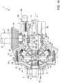
Figure 1 shows an axle comprising a differential group according to a first embodiment of the invention; -
Figure 2 shows a schematic sectional view, with parts removed for greater clarity, of a first embodiment of the differential group according to the invention in a first operating condition; -
Figure 3 shows a schematic sectional view, with parts removed for greater clarity, of the differential group offigure 2 in a second operating condition; -
Figures 4A and 4B show the differential group offigures 2 and3 , respectively, indicating, by means of arrows, the torque flow according to the invention in the two different operating conditions; -
Figure 5 shows an axle comprising a differential group according to a first example embodiment not according to the invention; -
Figure 6 shows a schematic sectional view, with parts removed for greater clarity, of the first example embodiment of the differential group in a first operating condition; -
Figure 7 shows a schematic sectional view, with parts removed for greater clarity, of the differential group offigure 6 in a second operating condition; -
Figures 8A and 8B show the differential group offigures 6 and7 , respectively, indicating, by means of arrows, the torque flow in the two different operating conditions; -
Figure 9 shows an axle comprising a differential group according to a second example embodiment not according to the invention; -
Figure 10 shows a schematic sectional view, with parts removed for greater clarity, of the second example embodiment of the differential group in a first operating condition; -
Figure 11 shows a schematic sectional view, with parts removed for greater clarity, of the differential group according offigure 10 in a second operating condition; and -
Figures 12A and 12B show the differential group offigures 10 and11 , respectively, indicating, by means of arrows, the torque flow in the two different operating conditions. - In the accompanying figures,
number 1 indicates adifferential group 1 according to the invention housed inside acasing 2 configured to delimit aninner space 3 suited for the purpose. Thecasing 2 further is advantageously configured to house part of theaxle shafts axle 6, as shown infigure 1 ,5 or9 . To this aim, thecasing 2 can be manufactured as one single piece or in different parts depending on the assembling needs of thedifferential group 1 and of theaxle 6. - The
differential group 1 is operatively interposed between theaxle shafts drive source 7, such as a transmission shaft configured to convey the torque of an internal combustion engine or an electric motor, which is configured to transmit a torque to theaxle shafts - The
axle shafts inner end differential group 1 and define a wheel hub atouter ends - The
differential group 1 comprises adifferential 8 and atransmission 9, thedifferential 8 being operatively interposed between theaxle shafts transmission 9 and the latter being operatively interposed between thedifferential 8 and thedrive source 7. - The
differential 8 is of a known type and comprises acarrier 11, which carries a plurality ofsatellites 13, for example four satellites, which are angularly equally spaced apart from one another by 90° and are supported by across-shaped support 14, which is rigidly carried by thecarrier 11 and around whose arms thesatellites 13 can rotate. In particular, the satellites rotate on thesupport 14 around axes contained in a plane, which is perpendicular to the axis A. - The
satellites 13 cooperate with a planetary comprising aleft bevel gear 15a and aright bevel gear 16b, respectively, which are rigidly carried by theaxle shaft 4 and by theaxle shaft 5, respectively, on the respective inner portion. - The
transmission 9 basically comprises arotating structure 16 and aplanetary gear 17, which are operatively interposed between thedrive source 7 and thecarrier 11. - In particular, the rotating
structure 16 is configured to define a closedspace 18 suited to house the planetary 17 and thedifferential 8. - According to the embodiment shown in
figures 2 and3 , therotating structure 16 is coaxial to the axis A of theaxle shafts inner ends axle shafts - The rotating
structure 16 is supported in a rotary manner by thecasing 2 by means ofrotary supports 19, such as for example ball bearings. The rotatingstructure 16 is operatively connected to thedrive source 7 by means of atoothed gear 21, which is rigidly carried by therotating structure 16 and is configured to cooperate with thedrive source 7 so as to allow a torque to be transmitted. In particular, in the embodiment described herein, thetoothed gear 21 is a bevel gear configured to mesh with arespective bevel gear 22 carried by ashaft 23 rotating around an axis B, which is perpendicular to the axis A of theaxle shafts - Preferably, the
rotating structure 16 is manufactured in different portions, in particular a first portion 16' defining the first opening 16a and asecond portion 16" defining the second opening 16b. The two portions 16', 16'' advantageously are rigidly connected to one another, for example through threaded means. - Preferably, the
toothed gear 21 is manufactured as a separate piece relative to saidportions 16', 16" and is rigidly connected to them. Advantageously, thetoothed gear 21 is connected, in a clamped manner, between the two portions 16', 16'' and is fixed to them through the same threaded means connecting them. - The planetary 17 comprises a plurality of
satellites 25, which are connected to thecarrier 11 of thedifferential 8, a solar 26, which is housed around one of theaxle shafts left axle shaft 4, and acrown 27, which is rigidly carried by therotating structure 16. - In particular, the
satellites 25 are free to rotate around apin 28 rigidly carried by thecarrier 11, for example through threaded means, and, hence, cooperate with atoothing 29 defined by thecrown 27 and with atoothing 31 defined by the solar 26. In particular, thepins 28 are arranged in an oblique manner relative to the axes A, B described above, advantageously inclined to define an acute angle α facing thedifferential 8. - The
crown 27 is advantageously manufactured as one single piece together with therotating structure 16 and, advantageously, is manufactured as one single piece together with the first portion 16', in particular it is defined by an axial projection inside thespace 18, more preferably close to the opening 16a. - The solar 26 comprises a
sleeve 32, which is housed around theaxle shaft 4 and is free to move relative to the latter both in a rotary and in a sliding manner, and areturn 33, which is coupled, in its rotation, to thesleeve 32 in an end portion of its. - In particular, the
return 33 and thesleeve 32 are coupled to one another in a rotary manner, but are free from a sliding point of view, so that thesleeve 32 can move along the axis A relative to thereturn 33. More in detail, thereturn 33 and thesleeve 32 are coupled by means of agrooved coupling 34 obtained by means of atoothing 35 extending in a radial direction from the inside of thereturn 33 and atoothing 36 extending in a radial direction on the outside of thesleeve 32 in an end portion thereof. - The
sleeve 32 further defines a further shape coupling, which can selectively be engaged with therotating structure 16. In particular, it defines afurther toothing 37 radially extending from its outer surface and arranged in an intermediate position between the two end portions of the sleeve as well as configured to selectively cooperate, in contact, with atoothing 38 carried by thecasing 2. In particular, thetoothing 38 radially extends from thecasing 2 towards theaxle shaft 4. - The
sleeve 32 further defines a further shape coupling, which can selectively be engaged with thepins 28 supporting thesatellites 25. In particular, it defines atoothing 39, which is obtained on an inner portion of thepins 25 facing thesleeve 32. In particular, thetoothing 36 defining thegrooved coupling 34 is sized so as to be able to selectively - and depending on the position of thesleeve 32 along the axis A - mesh with thetoothing 39. - Consequently to the embodiment described above, the
sleeve 32 is configured to move along the axis A so as to assume a first configuration (figure 2 ), in which the toothing 36 meshes with the sole toothing 35 of thecoupling 34 and, at the same time, the toothing 37 meshes with the toothing 38, thus making the solar 26 integral to thecasing 2. Thesleeve 32 further defines a second configuration (figure 3 ), in which the toothing 36 meshes with thetoothings 35 of thecoupling pins 28 and, at the same time, thetoothing 37 does not mesh with therespective toothing 38. - The
differential group 1 comprises actuator means 41, which are configured to allow the positioning of thesleeve 32 along the two positions mentioned above to be controlled. - In particular, the actuator means 41 are pneumatic actuator means and comprise a
chamber 42, in which apiston 43 is free to slide in a sealing manner. Thechamber 42 is fluidically connected to a source of air under pressure, so as to be selectively filled with or emptied from said air under pressure. Thepiston 43 is held in a rest position byelastic means 44, which are configured to exert, upon the piston, a force that is contrary to the one exerted by the pressure in thechamber 42 upon thepiston 43 itself. - The latter, hence, can slide in a sealing manner in the
chamber 42 depending on the force balance between the thrust provided by the elastic means 44 and the pressure of the air in thechamber 42 exerted on it. - The piston is further connected to the
sleeve 32 so that, when there is no air inside thechamber 42, it holds thesleeve 32 in the position offigure 3 , namely a position in which the rotatingstructure 16 and the solar 26 are free to rotate relative to one another, whereas, when there is air under pressure in thechamber 42, the thrust provided by the elastic means 44 acting upon thepiston 43 is overcome, thus causing the latter to move, moving thesleeve 32 to the position offigure 2 , namely a position in which the rotatingstructure 16 and the solar 26 are coupled to one another in a rotary manner. - The way in which the embodiment of the
differential group 1 described above operates is the following one and it will be described usingfigures 4A, 4B , which show the lines followed by the torque from thedrive source 7 to thedifferential 8. - In the condition of
figure 4A , the actuator means 41 are controlled so as to allow air to flow into thechamber 42. In this way, the force acting upon thepiston 43 overcomes the retaining force of the elastic means 44 and pushes thesleeve 32 so that it places itself in the operating condition in which thetoothing 35 meshes with thesole toothing 36 and, at the same time, thetoothing 37 meshes with thetoothing 38. In this condition, the torque coming from thedrive source 7 is transmitted from the gearing consisting of the toothed gears 21, 22 to the rotatingstructure 16, in order to then reach thesatellites 25, which rotate between thetoothing 31 of thereturn 33, fixed relative to thecasing 2, and thetoothing 29 of thecrown 27 and transmit said torque to thecarrier 11, to which they are rigidly connected. The latter splits the torque between theaxle shafts - In the condition of
figure 4B , the actuator means 41 are controlled so as to allow air to flow out of the chamber 42 (if present) or are at rest. In this way, the retaining force of the elastic means 44 holds thesleeve 32 in the operating condition in which thetoothing 35 meshes both with thetoothing 36 and with thetoothing 39 and, at the same time, thetoothing 37 does not mesh with thetoothing 38. In this condition, the torque coming from thedrive source 7 is transmitted from the gearing consisting of the toothed gears 21, 22 to the rotatingstructure 16 and, at the same time, to thesatellites 25 and to thereturn 33, which are all connected together to the rotation. Hence, thesatellites 25 directly cause the rotation of thecarrier 11 at the rotation velocity of thecasing 16. The latter splits the torque between theaxle shafts - Clearly, in the condition of
figure 4A , the torque is transmitted according to a different gear ratio compared to condition 4B. - According to the first example embodiment, not according to the present invention shown in
figures 6 and7 , the rotatingstructure 16 is coaxial to the axis A of theaxle shafts second opening axle shafts - The rotating
structure 16 is operatively connected to thedrive source 7 by means of atoothed gear 21, which is rigidly carried by the rotatingstructure 16 and is configured to cooperate with thedrive source 7 so as to allow a torque to be transmitted. In particular, in the embodiment described herein, thetoothed gear 21 is a bevel gear configured to mesh with arespective bevel gear 22 carried by ashaft 23 rotating around an axis B, which is perpendicular to the axis A of theaxle shafts - Preferably, the rotating
structure 16 is manufactured in different portions, in particular a first portion 16' defining thefirst opening 16a and a second portion 16'' defining thesecond opening 16b. The two portions 16', 16'' advantageously are rigidly connected to one another, for example through threaded means. - Preferably, the
toothed gear 21 is manufactured as a separate piece relative to saidportions 16', 16" and is rigidly connected to them. Advantageously, thetoothed gear 21 is connected, in a clamped manner, between the two portions 16', 16'' and is fixed to them through the same threaded means connecting them. - The planetary 17 comprises a plurality of
satellites 25, which are connected to thecarrier 11 of the differential 8, a solar 26, which is housed around one of theaxle shafts left axle shaft 4, and acrown 27, which is rigidly carried by the rotatingstructure 16. - In particular, the
satellites 25 are free to rotate around apin 28 rigidly carried by thecarrier 11 and, hence, cooperate with atoothing 29 defined by thecrown 27 and with atoothing 31 defined by the solar 26. In particular, thepins 28 are arranged in an oblique manner relative to the axes A, B described above, advantageously inclined to define an acute angle α facing the opposite side relative to thedifferential 8. - The
crown 27 is advantageously manufactured as one single piece together with thetoothed gear 21, in particular is defined on the opposite side relative to the toothing cooperating with thetoothed gear 22. - The solar 26 advantageously comprises a
sleeve 32, which is housed around theaxle shaft 4 and is free to move in a rotary manner relative to the latter. - The
sleeve 32 defines atoothing 51 radially extending from an end portion of thesleeve 32 extending towards the differential 8 and configured to mesh with thesatellites 25. Advantageously, given the inclination of thesatellites 25, saidtoothing 51 is a bevel toothing. - The
sleeve 32 also defines afurther toothing 52 preferably extending on the remaining portion of thesleeve 32. - The
differential group 1 further comprises aselector 53, which is configured to selectively connect thesleeve 32 to thecasing 2 or to the rotatingstructure 16. In particular, theselector 53 basically comprises a cylindrical annular element defining aninner toothing 54 facing thesleeve 32 and anouter toothing 55 facing the rotatingstructure 16. - The
inner toothing 54 is configured to constantly mesh with thetoothing 52 and slide along the axis A relative to thesleeve 32, whereas theouter toothing 55 is sized so as to selectively mesh with arespective toothing 56, which is rigidly connected to thecasing 2, or with arespective toothing 57, which is rigidly connected to the rotatingstructure 16. - In particular, in the case shown herein, the portion of
casing 2 shown is very small, for clarity reasons, whereas thetoothing 57 is obtained in the first portion of the rotating structure 16', in particular in the area of thefirst opening 16a. - Consequently to the embodiment described above, the
selector 53 is configured to move along the axis A so as to assume a first configuration (figure 6 ), in which thetoothing 55 meshes with thetoothing 56 of thecasing 2, thus making the solar 26 integral to the latter. Theselector 53 further defines a second configuration (figure 7 ), in which thetoothing 55 meshes with thetoothing 56; in this way, the solar 26 becomes integral to the rotatingstructure 16. - The
differential group 1 comprises actuator means 41, which are configured to allow the positioning of thesleeve 32 along the two positions mentioned above to be controlled. - In particular, the actuator means 41 are hydraulic actuator means and comprise a
hydraulic cylinder 60, for example a double-acting cylinder, which is configured to move arod 61, which is connected to theselector 53 and is configured to move it between the aforesaid first and second positions. - The way in which the embodiment of the
differential group 1 described above operates is the following one and it will be described usingfigures 8A, 8B , which show the lines followed by the torque from thedrive source 7 to thedifferential 8. - In the condition of
figure 8A , the actuator means 60 are controlled so as to move therod 61 in such a way that theselector 53 places itself in the operating condition in which thetoothing 55 meshes with thetoothing 56, thus causing thesleeve 32 to be coupled to thecasing 2. In this condition, the torque coming from thedrive source 7 is transmitted from the gearing consisting of the toothed gears 21, 22 to the rotatingstructure 16 and to thesatellites 25. They rotate between thetoothing 31 of thesleeve 32, which is fixed to thecasing 2 and to thetoothing 29 of thecrown 27, and transmit said torque to thecarrier 11, to which they are rigidly connected. The latter splits the torque between theaxle shafts - In the condition of
figure 8B , the actuator means 60 are controlled so as to move therod 61 in such a way that theselector 53 places itself in the operating condition in which thetoothing 55 meshes with thetoothing 57, thus causing thesleeve 32 to be coupled to the rotatingstructure 16. In this condition, the torque coming from thedrive source 7 is transmitted from the gearing consisting of the toothed gears 21, 22 to the rotatingstructure 16 and to thesatellites 25. They rotate between thetoothing 31 of thesleeve 32, which is fixed to the rotatingstructure 16 and to thetoothing 29 of thecrown 27, and, hence, transmit said torque from the rotatingstructure 16 to thecarrier 11, to which they are rigidly connected. The latter splits the torque between theaxle shafts - Clearly, in the condition of
figure 8A , the torque is transmitted according to a different gear ratio compared to condition 8B, in which the torque transmitted to thecarrier 11 is equal to the torque delivered to the rotatingstructure 16. - According to the second example embodiment, not according to the present invention shown in
figures 9 and10 , the rotatingstructure 16 is coaxial to the axis A of theaxle shafts second opening axle shafts - The rotating
structure 16 is operatively connected to thedrive source 7 by means of atoothed gear 21, which is rigidly carried by the rotatingstructure 16 and is configured to cooperate with thedrive source 7 so as to allow a torque to be transmitted. In particular, in the embodiment described herein, thetoothed gear 21 is a bevel gear configured to mesh with arespective bevel gear 22 carried by ashaft 23 rotating around an axis B, which is perpendicular to the axis A of theaxle shafts - Preferably, the rotating
structure 16 is manufactured in different portions, in particular a first portion 16' defining thefirst opening 16a and a second portion 16'' defining thesecond opening 16b. The two portions 16', 16'' advantageously are rigidly connected to one another, for example through threaded means. - Preferably, the
toothed gear 21 is manufactured as a separate piece relative to saidportions 16', 16" and is rigidly connected to them. Advantageously, thetoothed gear 21 is fixed to the portions 16', 16'' by means of the same threaded means connecting them, in particular is arranged on the outside of them, in particular facing thesecond portion 16". - The planetary 17 comprises a plurality of
satellites 25, which are connected to thecarrier 11 of the differential 8, a solar 26, which is housed around one of theaxle shafts right axle shaft 4, and acrown 27, which is rigidly carried by the rotatingstructure 16. - In particular, the
satellites 25 are free to rotate around apin 28 rigidly carried by thecarrier 11 and, hence, cooperate with atoothing 29 defined by thecrown 27 and with atoothing 31 defined by the solar 26. In particular, thepins 28 are arranged in an oblique manner relative to the axes A, B described above, advantageously inclined so as to define an acute angle α, whose origin substantially coincides with the central point of the differential 8, namely the symmetry axis of thecross-shaped support 14. In other words, the intersection of the longitudinal axes of thepin 28 substantially coincides with the intersection of the rotation axes of thesatellites 13 of the differential 8. - In particular, according to the embodiment shown herein, the
pins 28 are manufactured in an integral manner to thecarrier 11. - The
crown 27 is advantageously manufactured as one single piece together with one of the portions 16', 16'', in particular with the first portion 16', and basically comprises thetoothing 29 axially extending from said portion parallel to the axis A inside thespace 18. - The solar 26 advantageously comprises a
sleeve 32, which is housed around theaxle shaft 5 and is free to move in a rotary manner relative to the latter. - The
sleeve 32 defines atoothing 51 radially extending from an end portion of thesleeve 32 extending towards the differential 8 and configured to mesh with thesatellites 25. Advantageously, given the inclination of thesatellites 25, saidtoothing 51 is a bevel toothing. - The
sleeve 32 also defines afurther toothing 52 preferably extending on the remaining portion of thesleeve 32. - The
differential group 1 further comprises aselector 53, which is configured to selectively connect thesleeve 32 to thecasing 2 or to the rotatingstructure 16. In particular, theselector 53 basically comprises a cylindrical annular element defining aninner toothing 54 facing thesleeve 32 and anouter toothing 55 facing the rotatingstructure 16. - The
inner toothing 54 is configured to constantly mesh with thetoothing 52 and slide along the axis A relative to thesleeve 32, whereas theouter toothing 55 is sized so as to selectively mesh with arespective toothing 56, which is rigidly connected to thecasing 2, or with arespective toothing 57, which is rigidly connected to the rotatingstructure 16. - In particular, in the case shown herein, the portion of
casing 2 shown is very small, for clarity reasons, whereas thetoothing 57 is obtained in the second portion of the rotating structure 16'', in particular in the area of thesecond opening 16b. - Consequently to the embodiment described above, the
selector 53 is configured to move along the axis A so as to assume a first configuration (figure 11 ), in which thetoothing 55 meshes with thetoothing 56 of thecasing 2, thus making the solar 26 integral to the latter. Theselector 53 further defines a second configuration (figure 10 ), in which thetoothing 55 meshes with thetoothing 56; in this way, the solar 26 becomes integral to the rotatingstructure 16. - The
differential group 1 comprises actuator means 60, which are configured to allow the positioning of thesleeve 32 along the two positions mentioned above to be controlled. - In particular, the actuator means 60 are electromechanical actuator means and comprise an
electric motor 62 configured to operate aworm screw 61 meshing with a threadedring 63 rigidly carried by theselector 53 and configured to move it along the axis A depending on the rotation of theworm screw 61. - The way in which the embodiment of the
differential group 1 described above operates is the following one and it will be described usingfigures 12A, 12B , which show the lines followed by the torque from thedrive source 7 to thedifferential 8. - In the condition of
figure 12A , the actuator means 60 are controlled so as to move thescrew 61 in such a way that, by meshing with thering 62, it moves theselector 53 to the operating condition in which thetoothing 55 meshes with thetoothing 57, thus causing thesleeve 32 to be coupled to the rotatingstructure 16. In this condition, the torque coming from thedrive source 7 is transmitted from the gearing consisting of the toothed gears 21, 22 to the rotatingstructure 16 and to thesatellites 25. They rotate between thetoothing 31 of thesleeve 32, which is fixed to the rotatingstructure 16 and to thetoothing 29 of thecrown 27, and, hence, transmit said torque from the rotatingstructure 16 to thecarrier 11, to which they are rigidly connected. The latter splits the torque between theaxle shafts - In the condition of
figure 12B , the actuator means 60 are controlled so as to move thescrew 61 in such a way that, by meshing with thering 62, it moves theselector 53 to the operating condition in which thetoothing 55 meshes with thetoothing 56, thus causing thesleeve 32 to be coupled to thecasing 2. In this condition, the torque coming from thedrive source 7 is transmitted from the gearing consisting of the toothed gears 21, 22 to the rotatingstructure 16 and to thesatellites 25. They rotate between thetoothing 31 of thesleeve 32, which is fixed to thecasing 2 and to thetoothing 29 of thecrown 27, and transmit said torque to thecarrier 11, to which they are rigidly connected. The latter splits the torque between theaxle shafts figure 8A , the torque is transmitted according to a different gear ratio compared to condition 8B, in which the torque transmitted to thecarrier 11 is equal to the torque delivered to the rotatingstructure 16. - In all embodiments described above, the
differential group 1 further comprises several functional elements, such as anti-dust rings, spacers, o-rings, threaded elements, splines or bearings configured to allow a correct assembly and operation of the structure schematically disclosed above, which are not discussed in the detail for the sake of brevity. - Furthermore, known differential locking means can be provided, which are not shown herein.
- Owing to the above, the advantages of a
differential group 1 according to the invention are evident. - In particular, the
differential group 1 allows for two possible gear ratios between thedrive source 7 and the differential 8, thus increasing the versatility of the driving system of the heavy vehicle. In this way, it is possible to provide a versatile differential group for different types of driving styles and loads of the vehicle. - Furthermore, the
differential group 1 is particularly compact thanks to the specific arrangement of the elements that are part of the rotatingstructure 16 and of the planetary 17. In particular, all the main gears of thedifferential group 1 are isolated from the outside, since they are wrapped inside thecasing 2 and the rotatingstructure 16. - In this way, contaminations from the outside can be avoided, thus increasing the useful life of the differential group.
- The specific arrangement of the axes of the
pins 28 and the fact that the crown is obtained on the inside of the rotatingstructure 16 allow for an extremely compact planetary. - Finally, the
differential group 1 according to the invention can be subjected to changes and variants, which, though, do not go beyond the scope of protection set forth in the appendedclaim 1. - For example, it is clear that the actuator means 41, 60, 70 can be different and be used in an equivalent manner as well as in combination in any one of the embodiments described above.
- Furthermore, the pairs of toothed gears described above can be of any type and dimension. Furthermore, the position of the
toothed gear 21, the existence of theselector 53 or the direct actuation of thesleeve 32 by the actuator means can be changed by combining the different embodiments described herein. - Similarly, the shape of the
structure 2 or of theaxle 6 can change depending on the type of vehicle, just like the elements of the differential 8.
Claims (13)
- Differential group (1) for a heavy vehicle, said differential group (1) comprising a casing (2) defining a space (3), a differential (8) and a transmission (9) housed inside said space (3),said differential (8) being configured to divide an input torque from a drive source (7) to said differential group (1) to a torque of axle shafts (4, 5) of said vehicle coaxial around an axis (A),said transmission (9) being operatively interposed between said driving source (7) and said differential (8) and comprising a rotating structure (16) carried rotationally free from said casing (2) and a planetary (17),said rotating structure (16) being operatively interposed between said driving source (7) and said planetary (17) and defining a space (18) housing said planetary (17) and said differential (8),said planetary (17) comprising:a solar (26) rotationally carried around one of the axle shafts (4, 5) and defining a toothing (31),a crown (27) rigidly carried by said rotating structure (16) and defining a toothing (29), anda plurality of satellites (25) meshing with said toothing (29, 31) of said solar (26) and said crown (27) and configured to rotate around a pin (28) rigidly carried by a carrier (11) of said differential,said differential group (1) comprising actuator means (41, 60, 70) configured to control said solar (26) so that it assumes a first operating condition in which it is rotationally coupled to said rotating structure (16) or a second operating condition in the which is rotationally coupled to said casing (2), characterized in that said solar(26) comprises a sleeve (32) operated by said actuator means (41) to move along said axis (A) and positioned around one of the axle shafts (4, 5),said sleeve (32) also defining a first toothing (35) and a second toothing (37) configured respectively to mesh alternately with respective teeth (39, 38) carried by each pin (28) of said satellites (25) and by said carcass (2) as a function of the position of said sleeve on said axis (A).
- Differential group according to claim 1, wherein said solar (26) comprises a return (33) defining said toothing (31) and rotationally coupled to said sleeve (32) by means of a grooved coupling made between a toothing (36) carried by said return (33) and said first toothing (35) of said sleeve (32), said first toothing (35) meshing simultaneously with said pin (28) and said toothing (36) of said return according to the position of said sleeve on said axis (A).
- Differential group according to claim 1, wherein said solar (26) comprises a sleeve (32) defining said toothing 29) and housed around one of the axle shafts (4, 5)and a selector (53) operated by said actuator means (41) to move along said A and positioned around said sleeve (32) and rotationally coupled thereto,said selector (53) also defining a toothing (55) configured to alternately mesh with respective toothings (56, 57) carried by said casing (2) and by said rotating structure (56) thus making said sleeve (32) alternately integral with them.
- Differential group according to one of the preceding claims, wherein said rotating structure (16) defines a toothing (21) configured to cooperate with said driving source (7) to transfer said torque to said rotating structure (16).
- Differential group according to claim 4, wherein said rotating structure (16) is made in two portions (16 ', 16' '), said toothing (21) being made on a separate element and clamped between said two portions (16', 16").
- Differential group according to claim 4, wherein said rotating structure (16) is made in two portions (16', 16"), said toothing (21) being made on a separate element fixed to one of said portions (16').
- Differential unit according to one of the preceding claims, wherein said crown (27) is made in one piece to said rotating structure (16).
- Differential group according to one of claims 4 to 7, wherein said crown (27) is made in one piece with said toothing (21).
- Differential group according to one of the preceding claims, wherein a longitudinal axis of said pin (28) of said satellites (25) is positioned obliquely with respect to said axis (A).
- Differential group according to claim 9, in which the intersection of the longitudinal axes of said pins (28) coincides with the intersection of the rotation axes of said satellites (13) of said differential (8).
- The differential assembly of claim 9, wherein said pins (28) are integrally made to said tractor carrier (11).
- Differential unit according to one of the preceding claims wherein said actuator means (41, 60, 70) comprise at least one of a pneumatic, hydraulic, mechanical actuator.
- Vehicle axle (6) comprises a first and a second axle shaft (4, 5) and a differential unit (1) configured to connect said axle shafts (4, 5) to a driving source (7) of said vehicle, said differential assembly (1) being made according to one of the preceding claims.
Applications Claiming Priority (2)
| Application Number | Priority Date | Filing Date | Title |
|---|---|---|---|
| IT102020000010891A IT202000010891A1 (en) | 2020-05-13 | 2020-05-13 | DIFFERENTIAL GROUP AT DIFFERENT SPEED |
| PCT/IB2021/054099 WO2021229491A1 (en) | 2020-05-13 | 2021-05-13 | Differential unit with different velocities |
Publications (2)
| Publication Number | Publication Date |
|---|---|
| EP4150233A1 EP4150233A1 (en) | 2023-03-22 |
| EP4150233B1 true EP4150233B1 (en) | 2024-10-30 |
Family
ID=71784557
Family Applications (1)
| Application Number | Title | Priority Date | Filing Date |
|---|---|---|---|
| EP21730656.2A Active EP4150233B1 (en) | 2020-05-13 | 2021-05-13 | Differential unit with different velocities |
Country Status (4)
| Country | Link |
|---|---|
| EP (1) | EP4150233B1 (en) |
| BR (1) | BR112022023000A2 (en) |
| IT (1) | IT202000010891A1 (en) |
| WO (1) | WO2021229491A1 (en) |
Family Cites Families (5)
| Publication number | Priority date | Publication date | Assignee | Title |
|---|---|---|---|---|
| US2053929A (en) * | 1934-09-20 | 1936-09-08 | Wiedmaier Inc | Power transmission mechanism |
| GB587312A (en) * | 1943-04-29 | 1947-04-22 | Timken Axle Co Detroit | Multi-speed drive axle |
| GB808543A (en) * | 1955-12-16 | 1959-02-04 | Daimler Benz Ag | An axle-driving arrangement for a motor vehicle |
| JP2922476B2 (en) * | 1997-02-17 | 1999-07-26 | 庄司 井学 | Planetary gear without sub-carrier panel |
| CN109153326B (en) * | 2016-04-05 | 2022-04-19 | 沃尔沃建筑设备公司 | Planetary Carriers and Planetary Gear Transmissions |
-
2020
- 2020-05-13 IT IT102020000010891A patent/IT202000010891A1/en unknown
-
2021
- 2021-05-13 WO PCT/IB2021/054099 patent/WO2021229491A1/en not_active Ceased
- 2021-05-13 BR BR112022023000A patent/BR112022023000A2/en unknown
- 2021-05-13 EP EP21730656.2A patent/EP4150233B1/en active Active
Also Published As
| Publication number | Publication date |
|---|---|
| BR112022023000A2 (en) | 2023-01-17 |
| EP4150233A1 (en) | 2023-03-22 |
| WO2021229491A1 (en) | 2021-11-18 |
| IT202000010891A1 (en) | 2021-11-13 |
Similar Documents
| Publication | Publication Date | Title |
|---|---|---|
| US7211017B2 (en) | Inter-axle differential lock shift mechanism | |
| CN108569085B (en) | Axle assembly with multiple clutch collars | |
| KR830002124B1 (en) | Axle disconnection device for automotive differential gear | |
| JP5511049B2 (en) | Axle decoupling assembly | |
| US3969950A (en) | Drive assembly | |
| US4934213A (en) | Power transmission apparatus | |
| WO1981001596A1 (en) | Liquid cooled disc brake for differential of tracked vehicle | |
| EP3925811B1 (en) | Wheel hub for a vehicle axle with an improved integrated reduction gear system | |
| EP4150233B1 (en) | Differential unit with different velocities | |
| EP4279765A1 (en) | Wheel hub for a vehicle axle comprising an improved integrated reduction system | |
| EP4422898B1 (en) | Traction assembly for a vehicle | |
| US6248038B1 (en) | Direction reversing transmission gear for vehicle | |
| EP4150234B1 (en) | Differential unit with different velocities | |
| EP4149784B1 (en) | Differential unit with different velocities | |
| CN119840414A (en) | Axle assembly with clutch collar | |
| KR102519195B1 (en) | Limited slip differential for vehicles and electric drive apparatus including same | |
| US11391370B2 (en) | Shift fork actuation assembly | |
| US11320033B2 (en) | Differential assembly for shifting | |
| EP0328300B1 (en) | Differential clutch with gear reaction | |
| EP3705752B1 (en) | Differential assembly with multiple velocities | |
| EP4144552B1 (en) | Traction assembly for a vehicle | |
| EP3785970A1 (en) | Motor assembly with integrated multiple velocity differential | |
| EP2302246B1 (en) | A rotary transmission coupling | |
| EP4257401A1 (en) | Improved torque distributor system among axles of a heavy vehicle | |
| EP4144554A1 (en) | Traction assembly for a vehicle |
Legal Events
| Date | Code | Title | Description |
|---|---|---|---|
| STAA | Information on the status of an ep patent application or granted ep patent |
Free format text: STATUS: UNKNOWN |
|
| STAA | Information on the status of an ep patent application or granted ep patent |
Free format text: STATUS: THE INTERNATIONAL PUBLICATION HAS BEEN MADE |
|
| PUAI | Public reference made under article 153(3) epc to a published international application that has entered the european phase |
Free format text: ORIGINAL CODE: 0009012 |
|
| STAA | Information on the status of an ep patent application or granted ep patent |
Free format text: STATUS: REQUEST FOR EXAMINATION WAS MADE |
|
| 17P | Request for examination filed |
Effective date: 20221118 |
|
| AK | Designated contracting states |
Kind code of ref document: A1 Designated state(s): AL AT BE BG CH CY CZ DE DK EE ES FI FR GB GR HR HU IE IS IT LI LT LU LV MC MK MT NL NO PL PT RO RS SE SI SK SM TR |
|
| DAV | Request for validation of the european patent (deleted) | ||
| DAX | Request for extension of the european patent (deleted) | ||
| GRAP | Despatch of communication of intention to grant a patent |
Free format text: ORIGINAL CODE: EPIDOSNIGR1 |
|
| STAA | Information on the status of an ep patent application or granted ep patent |
Free format text: STATUS: GRANT OF PATENT IS INTENDED |
|
| INTG | Intention to grant announced |
Effective date: 20240522 |
|
| P01 | Opt-out of the competence of the unified patent court (upc) registered |
Effective date: 20240523 |
|
| GRAS | Grant fee paid |
Free format text: ORIGINAL CODE: EPIDOSNIGR3 |
|
| GRAA | (expected) grant |
Free format text: ORIGINAL CODE: 0009210 |
|
| STAA | Information on the status of an ep patent application or granted ep patent |
Free format text: STATUS: THE PATENT HAS BEEN GRANTED |
|
| AK | Designated contracting states |
Kind code of ref document: B1 Designated state(s): AL AT BE BG CH CY CZ DE DK EE ES FI FR GB GR HR HU IE IS IT LI LT LU LV MC MK MT NL NO PL PT RO RS SE SI SK SM TR |
|
| REG | Reference to a national code |
Ref country code: GB Ref legal event code: FG4D |
|
| REG | Reference to a national code |
Ref country code: CH Ref legal event code: EP |
|
| REG | Reference to a national code |
Ref country code: IE Ref legal event code: FG4D |
|
| REG | Reference to a national code |
Ref country code: DE Ref legal event code: R096 Ref document number: 602021021020 Country of ref document: DE |
|
| REG | Reference to a national code |
Ref country code: LT Ref legal event code: MG9D |
|
| REG | Reference to a national code |
Ref country code: NL Ref legal event code: MP Effective date: 20241030 |
|
| PG25 | Lapsed in a contracting state [announced via postgrant information from national office to epo] |
Ref country code: PT Free format text: LAPSE BECAUSE OF FAILURE TO SUBMIT A TRANSLATION OF THE DESCRIPTION OR TO PAY THE FEE WITHIN THE PRESCRIBED TIME-LIMIT Effective date: 20250228 Ref country code: IS Free format text: LAPSE BECAUSE OF FAILURE TO SUBMIT A TRANSLATION OF THE DESCRIPTION OR TO PAY THE FEE WITHIN THE PRESCRIBED TIME-LIMIT Effective date: 20250228 Ref country code: HR Free format text: LAPSE BECAUSE OF FAILURE TO SUBMIT A TRANSLATION OF THE DESCRIPTION OR TO PAY THE FEE WITHIN THE PRESCRIBED TIME-LIMIT Effective date: 20241030 |
|
| PG25 | Lapsed in a contracting state [announced via postgrant information from national office to epo] |
Ref country code: FI Free format text: LAPSE BECAUSE OF FAILURE TO SUBMIT A TRANSLATION OF THE DESCRIPTION OR TO PAY THE FEE WITHIN THE PRESCRIBED TIME-LIMIT Effective date: 20241030 Ref country code: NL Free format text: LAPSE BECAUSE OF FAILURE TO SUBMIT A TRANSLATION OF THE DESCRIPTION OR TO PAY THE FEE WITHIN THE PRESCRIBED TIME-LIMIT Effective date: 20241030 |
|
| REG | Reference to a national code |
Ref country code: AT Ref legal event code: MK05 Ref document number: 1737153 Country of ref document: AT Kind code of ref document: T Effective date: 20241030 |
|
| PG25 | Lapsed in a contracting state [announced via postgrant information from national office to epo] |
Ref country code: BG Free format text: LAPSE BECAUSE OF FAILURE TO SUBMIT A TRANSLATION OF THE DESCRIPTION OR TO PAY THE FEE WITHIN THE PRESCRIBED TIME-LIMIT Effective date: 20241030 |
|
| PG25 | Lapsed in a contracting state [announced via postgrant information from national office to epo] |
Ref country code: ES Free format text: LAPSE BECAUSE OF FAILURE TO SUBMIT A TRANSLATION OF THE DESCRIPTION OR TO PAY THE FEE WITHIN THE PRESCRIBED TIME-LIMIT Effective date: 20241030 |
|
| PG25 | Lapsed in a contracting state [announced via postgrant information from national office to epo] |
Ref country code: NO Free format text: LAPSE BECAUSE OF FAILURE TO SUBMIT A TRANSLATION OF THE DESCRIPTION OR TO PAY THE FEE WITHIN THE PRESCRIBED TIME-LIMIT Effective date: 20250130 |
|
| PG25 | Lapsed in a contracting state [announced via postgrant information from national office to epo] |
Ref country code: LV Free format text: LAPSE BECAUSE OF FAILURE TO SUBMIT A TRANSLATION OF THE DESCRIPTION OR TO PAY THE FEE WITHIN THE PRESCRIBED TIME-LIMIT Effective date: 20241030 Ref country code: GR Free format text: LAPSE BECAUSE OF FAILURE TO SUBMIT A TRANSLATION OF THE DESCRIPTION OR TO PAY THE FEE WITHIN THE PRESCRIBED TIME-LIMIT Effective date: 20250131 Ref country code: AT Free format text: LAPSE BECAUSE OF FAILURE TO SUBMIT A TRANSLATION OF THE DESCRIPTION OR TO PAY THE FEE WITHIN THE PRESCRIBED TIME-LIMIT Effective date: 20241030 |
|
| PG25 | Lapsed in a contracting state [announced via postgrant information from national office to epo] |
Ref country code: PL Free format text: LAPSE BECAUSE OF FAILURE TO SUBMIT A TRANSLATION OF THE DESCRIPTION OR TO PAY THE FEE WITHIN THE PRESCRIBED TIME-LIMIT Effective date: 20241030 |
|
| PG25 | Lapsed in a contracting state [announced via postgrant information from national office to epo] |
Ref country code: RS Free format text: LAPSE BECAUSE OF FAILURE TO SUBMIT A TRANSLATION OF THE DESCRIPTION OR TO PAY THE FEE WITHIN THE PRESCRIBED TIME-LIMIT Effective date: 20250130 |
|
| PG25 | Lapsed in a contracting state [announced via postgrant information from national office to epo] |
Ref country code: SM Free format text: LAPSE BECAUSE OF FAILURE TO SUBMIT A TRANSLATION OF THE DESCRIPTION OR TO PAY THE FEE WITHIN THE PRESCRIBED TIME-LIMIT Effective date: 20241030 |
|
| PGFP | Annual fee paid to national office [announced via postgrant information from national office to epo] |
Ref country code: DE Payment date: 20250528 Year of fee payment: 5 |
|
| PG25 | Lapsed in a contracting state [announced via postgrant information from national office to epo] |
Ref country code: DK Free format text: LAPSE BECAUSE OF FAILURE TO SUBMIT A TRANSLATION OF THE DESCRIPTION OR TO PAY THE FEE WITHIN THE PRESCRIBED TIME-LIMIT Effective date: 20241030 |
|
| PGFP | Annual fee paid to national office [announced via postgrant information from national office to epo] |
Ref country code: IT Payment date: 20250512 Year of fee payment: 5 |
|
| PG25 | Lapsed in a contracting state [announced via postgrant information from national office to epo] |
Ref country code: EE Free format text: LAPSE BECAUSE OF FAILURE TO SUBMIT A TRANSLATION OF THE DESCRIPTION OR TO PAY THE FEE WITHIN THE PRESCRIBED TIME-LIMIT Effective date: 20241030 |
|
| PGFP | Annual fee paid to national office [announced via postgrant information from national office to epo] |
Ref country code: FR Payment date: 20250526 Year of fee payment: 5 |
|
| PG25 | Lapsed in a contracting state [announced via postgrant information from national office to epo] |
Ref country code: RO Free format text: LAPSE BECAUSE OF FAILURE TO SUBMIT A TRANSLATION OF THE DESCRIPTION OR TO PAY THE FEE WITHIN THE PRESCRIBED TIME-LIMIT Effective date: 20241030 |
|
| PG25 | Lapsed in a contracting state [announced via postgrant information from national office to epo] |
Ref country code: SK Free format text: LAPSE BECAUSE OF FAILURE TO SUBMIT A TRANSLATION OF THE DESCRIPTION OR TO PAY THE FEE WITHIN THE PRESCRIBED TIME-LIMIT Effective date: 20241030 |
|
| PG25 | Lapsed in a contracting state [announced via postgrant information from national office to epo] |
Ref country code: CZ Free format text: LAPSE BECAUSE OF FAILURE TO SUBMIT A TRANSLATION OF THE DESCRIPTION OR TO PAY THE FEE WITHIN THE PRESCRIBED TIME-LIMIT Effective date: 20241030 |
|
| REG | Reference to a national code |
Ref country code: DE Ref legal event code: R097 Ref document number: 602021021020 Country of ref document: DE |
|
| PLBE | No opposition filed within time limit |
Free format text: ORIGINAL CODE: 0009261 |
|
| STAA | Information on the status of an ep patent application or granted ep patent |
Free format text: STATUS: NO OPPOSITION FILED WITHIN TIME LIMIT |
|
| PG25 | Lapsed in a contracting state [announced via postgrant information from national office to epo] |
Ref country code: SE Free format text: LAPSE BECAUSE OF FAILURE TO SUBMIT A TRANSLATION OF THE DESCRIPTION OR TO PAY THE FEE WITHIN THE PRESCRIBED TIME-LIMIT Effective date: 20241030 |
|
| 26N | No opposition filed |
Effective date: 20250731 |
|
| REG | Reference to a national code |
Ref country code: CH Ref legal event code: H13 Free format text: ST27 STATUS EVENT CODE: U-0-0-H10-H13 (AS PROVIDED BY THE NATIONAL OFFICE) Effective date: 20251223 |
|
| PG25 | Lapsed in a contracting state [announced via postgrant information from national office to epo] |
Ref country code: LU Free format text: LAPSE BECAUSE OF NON-PAYMENT OF DUE FEES Effective date: 20250513 |
|
| PG25 | Lapsed in a contracting state [announced via postgrant information from national office to epo] |
Ref country code: CH Free format text: LAPSE BECAUSE OF NON-PAYMENT OF DUE FEES Effective date: 20250531 |
|
| GBPC | Gb: european patent ceased through non-payment of renewal fee |
Effective date: 20250513 |
|
| REG | Reference to a national code |
Ref country code: BE Ref legal event code: MM Effective date: 20250531 |
|
| PG25 | Lapsed in a contracting state [announced via postgrant information from national office to epo] |
Ref country code: MC Free format text: LAPSE BECAUSE OF FAILURE TO SUBMIT A TRANSLATION OF THE DESCRIPTION OR TO PAY THE FEE WITHIN THE PRESCRIBED TIME-LIMIT Effective date: 20241030 |
|
| PG25 | Lapsed in a contracting state [announced via postgrant information from national office to epo] |
Ref country code: GB Free format text: LAPSE BECAUSE OF NON-PAYMENT OF DUE FEES Effective date: 20250513 |
|
| PG25 | Lapsed in a contracting state [announced via postgrant information from national office to epo] |
Ref country code: IE Free format text: LAPSE BECAUSE OF NON-PAYMENT OF DUE FEES Effective date: 20250513 |
|
| PG25 | Lapsed in a contracting state [announced via postgrant information from national office to epo] |
Ref country code: BE Free format text: LAPSE BECAUSE OF NON-PAYMENT OF DUE FEES Effective date: 20250531 |