EP4149784B1 - Differential unit with different velocities - Google Patents
Differential unit with different velocities Download PDFInfo
- Publication number
- EP4149784B1 EP4149784B1 EP21731831.0A EP21731831A EP4149784B1 EP 4149784 B1 EP4149784 B1 EP 4149784B1 EP 21731831 A EP21731831 A EP 21731831A EP 4149784 B1 EP4149784 B1 EP 4149784B1
- Authority
- EP
- European Patent Office
- Prior art keywords
- differential
- differential group
- group according
- portions
- shafts
- Prior art date
- Legal status (The legal status is an assumption and is not a legal conclusion. Google has not performed a legal analysis and makes no representation as to the accuracy of the status listed.)
- Active
Links
- 230000008878 coupling Effects 0.000 claims description 23
- 238000010168 coupling process Methods 0.000 claims description 23
- 238000005859 coupling reaction Methods 0.000 claims description 23
- 230000005540 biological transmission Effects 0.000 claims description 19
- 230000001419 dependent effect Effects 0.000 claims description 2
- 230000000903 blocking effect Effects 0.000 description 5
- 238000007789 sealing Methods 0.000 description 4
- 230000009471 action Effects 0.000 description 1
- 230000008859 change Effects 0.000 description 1
- 238000002485 combustion reaction Methods 0.000 description 1
- 238000011109 contamination Methods 0.000 description 1
- 239000000428 dust Substances 0.000 description 1
- 238000005096 rolling process Methods 0.000 description 1
- 125000006850 spacer group Chemical group 0.000 description 1
Images


Classifications
-
- F—MECHANICAL ENGINEERING; LIGHTING; HEATING; WEAPONS; BLASTING
- F16—ENGINEERING ELEMENTS AND UNITS; GENERAL MEASURES FOR PRODUCING AND MAINTAINING EFFECTIVE FUNCTIONING OF MACHINES OR INSTALLATIONS; THERMAL INSULATION IN GENERAL
- F16H—GEARING
- F16H37/00—Combinations of mechanical gearings, not provided for in groups F16H1/00 - F16H35/00
- F16H37/02—Combinations of mechanical gearings, not provided for in groups F16H1/00 - F16H35/00 comprising essentially only toothed or friction gearings
- F16H37/06—Combinations of mechanical gearings, not provided for in groups F16H1/00 - F16H35/00 comprising essentially only toothed or friction gearings with a plurality of driving or driven shafts; with arrangements for dividing torque between two or more intermediate shafts
- F16H37/08—Combinations of mechanical gearings, not provided for in groups F16H1/00 - F16H35/00 comprising essentially only toothed or friction gearings with a plurality of driving or driven shafts; with arrangements for dividing torque between two or more intermediate shafts with differential gearing
- F16H37/0806—Combinations of mechanical gearings, not provided for in groups F16H1/00 - F16H35/00 comprising essentially only toothed or friction gearings with a plurality of driving or driven shafts; with arrangements for dividing torque between two or more intermediate shafts with differential gearing with a plurality of driving or driven shafts
- F16H37/0813—Combinations of mechanical gearings, not provided for in groups F16H1/00 - F16H35/00 comprising essentially only toothed or friction gearings with a plurality of driving or driven shafts; with arrangements for dividing torque between two or more intermediate shafts with differential gearing with a plurality of driving or driven shafts with only one input shaft
-
- F—MECHANICAL ENGINEERING; LIGHTING; HEATING; WEAPONS; BLASTING
- F16—ENGINEERING ELEMENTS AND UNITS; GENERAL MEASURES FOR PRODUCING AND MAINTAINING EFFECTIVE FUNCTIONING OF MACHINES OR INSTALLATIONS; THERMAL INSULATION IN GENERAL
- F16H—GEARING
- F16H48/00—Differential gearings
- F16H48/38—Constructional details
- F16H48/42—Constructional details characterised by features of the input shafts, e.g. mounting of drive gears thereon
-
- B—PERFORMING OPERATIONS; TRANSPORTING
- B60—VEHICLES IN GENERAL
- B60K—ARRANGEMENT OR MOUNTING OF PROPULSION UNITS OR OF TRANSMISSIONS IN VEHICLES; ARRANGEMENT OR MOUNTING OF PLURAL DIVERSE PRIME-MOVERS IN VEHICLES; AUXILIARY DRIVES FOR VEHICLES; INSTRUMENTATION OR DASHBOARDS FOR VEHICLES; ARRANGEMENTS IN CONNECTION WITH COOLING, AIR INTAKE, GAS EXHAUST OR FUEL SUPPLY OF PROPULSION UNITS IN VEHICLES
- B60K17/00—Arrangement or mounting of transmissions in vehicles
- B60K17/04—Arrangement or mounting of transmissions in vehicles characterised by arrangement, location, or kind of gearing
- B60K17/16—Arrangement or mounting of transmissions in vehicles characterised by arrangement, location, or kind of gearing of differential gearing
- B60K17/165—Arrangement or mounting of transmissions in vehicles characterised by arrangement, location, or kind of gearing of differential gearing provided between independent half axles
-
- F—MECHANICAL ENGINEERING; LIGHTING; HEATING; WEAPONS; BLASTING
- F16—ENGINEERING ELEMENTS AND UNITS; GENERAL MEASURES FOR PRODUCING AND MAINTAINING EFFECTIVE FUNCTIONING OF MACHINES OR INSTALLATIONS; THERMAL INSULATION IN GENERAL
- F16H—GEARING
- F16H48/00—Differential gearings
- F16H48/20—Arrangements for suppressing or influencing the differential action, e.g. locking devices
- F16H48/30—Arrangements for suppressing or influencing the differential action, e.g. locking devices using externally-actuatable means
- F16H2048/305—Arrangements for suppressing or influencing the differential action, e.g. locking devices using externally-actuatable means using manual actuators
-
- F—MECHANICAL ENGINEERING; LIGHTING; HEATING; WEAPONS; BLASTING
- F16—ENGINEERING ELEMENTS AND UNITS; GENERAL MEASURES FOR PRODUCING AND MAINTAINING EFFECTIVE FUNCTIONING OF MACHINES OR INSTALLATIONS; THERMAL INSULATION IN GENERAL
- F16H—GEARING
- F16H48/00—Differential gearings
- F16H48/38—Constructional details
- F16H2048/385—Constructional details of the ring or crown gear
-
- F—MECHANICAL ENGINEERING; LIGHTING; HEATING; WEAPONS; BLASTING
- F16—ENGINEERING ELEMENTS AND UNITS; GENERAL MEASURES FOR PRODUCING AND MAINTAINING EFFECTIVE FUNCTIONING OF MACHINES OR INSTALLATIONS; THERMAL INSULATION IN GENERAL
- F16H—GEARING
- F16H57/00—General details of gearing
- F16H57/02—Gearboxes; Mounting gearing therein
- F16H2057/02039—Gearboxes for particular applications
- F16H2057/02043—Gearboxes for particular applications for vehicle transmissions
- F16H2057/0206—Gearboxes for particular applications for vehicle transmissions for commercial vehicles, e.g. buses or trucks
Definitions
- the invention relates to a differential unit, more in particular to a differential group for a heavy vehicle, such as a truck.
- the differential is a power transmission member available in vehicles to distribute the torque coming from an input shaft to a pair of output shafts connected to respective wheels.
- the differential allows different velocities to be delivered to the wheels, so as to allow each one of them to follow the relative trajectory during paths covering a bend or paths with different grips.
- a differential comprises a carrier, to which two shafts are constrained, and two satellites, which are placed on the shafts and mesh with two driven planetary gears, which are integral to the axle shafts, each connected to the respective wheel.
- Known differentials are also provided with a locking function, which is configured to cause the two axle shafts to be integral to one another. This function is useful in case of a surface allowing for a reduced grip of the tyres, in which case one of the two wheels, if it were not constrained to the other one, would tend to skid, thus dispersing the torque.
- the object of the invention is to fulfil the needs discussed above in an economic fashion.
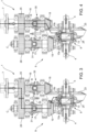
- number 1 indicates a differential group 1 according to the invention housed inside a casing 2 configured to delimit an inner space 3 suited for the purpose.
- the casing 2 further is advantageously configured to house part of the axle shafts 4, 5 of an axle 6, as shown in figure 5 .
- the casing 2 can be manufactured as one single piece or in different parts depending on the assembling needs of the differential group 1 and of the axle 6.
- the differential group 1 is operatively interposed between the axle shafts 4, 5 and a drive source 7, such as a transmission shaft configured to convey the torque of an internal combustion engine or an electric motor, which is configured to transmit a torque to the axle shafts 4, 5.
- a drive source 7 such as a transmission shaft configured to convey the torque of an internal combustion engine or an electric motor, which is configured to transmit a torque to the axle shafts 4, 5.
- axle shafts 4, 5, as it is known, are advantageously concentric to one another around a common longitudinal axis A, cooperate - with a respective inner end 4a, 5a - with the differential group 1 and define a wheel hub at outer ends 4b, 5b of theirs.
- the differential group 1 comprises a differential 8 and a transmission 9, the differential 8 being operatively interposed between the axle shafts 4, 5 and the transmission 9 and the latter being operatively interposed between the differential 8 and the drive source 7.
- the differential 8 is known and comprises a carrier 11, which is carried by the casing 3 so as to freely rotate, for example by means of ball bearings 12. According to the embodiment described herein, the carrier 11 is operatively connected to the transmission 9 as described below.
- the carrier 11 carries a plurality of satellites 13, for example four satellites, which are angularly equally spaced apart from one another by 90° and are supported by a cross-shaped support 14, which is rigidly carried by the carrier 14 and around whose arms the satellites 13 can rotate.
- the satellites rotate on the support 14 around axes contained in a plane, which is perpendicular to the axis A.
- the satellites 13 cooperate with a planetary comprising a left bevel gear 15a and a right bevel gear 16b, respectively, which are rigidly carried by the axle shaft 4 and by the axle shaft 5, respectively, on the respective inner portion.
- the transmission 9 basically comprises a first and a second shaft 16, 17, which are arranged along respective axes B, C perpendicular to the axis A and, hence, parallel to one another and selectively mesh with the carrier 11 as described below.
- Each shaft 16, 17 defines an outer end 16a, 17a and an inner end 16b, 17b, the latter being closer to the differential 8.
- Each shaft 16, 17 carries a respective gear wheel 18, 19, which is rigidly carried by the inner end 16b, 17b and is configured to mesh with the carrier 11.
- the carrier 11 comprises an annular portion 21, which is coaxial to the axis A, defines the openings configured to allow the axle shafts 4, 5 to be housed and is configured to surround the satellites 13 and the gear wheels 15a, 15b.
- the carrier 11 further comprises a flange 22 radially extending from the annular portion 21, namely perpendicularly to the axis A towards the transmission 9.
- the annular portion 21 defines the support for the cross-shaped support 14 and the flange 22, which preferably is separate and fixed to the annular portion 21 and defines, at a radial end of its, a pair of toothings 23, 24, which are configured to mesh with the gear wheels 18, 19 carried by the shafts 16, 17 of the transmission 8.
- the toothings 23, 24 are advantageously obtained on axially opposite sides of the flange 22, which extends in an intermediate position between the axes B, C, preferably substantially in the middle between them. Hence, advantageously, the toothings 23, 24 rotate around the axis A, whereas the gear wheels 18, 19 rotate around the axes B, C, thus meshing with one another defining respective bevel gears.
- the transmission 9 further comprises a further pair of gear wheels 25, 26, the first one being carried by the first shaft 16 and the second one being carried by the second haft 17 and meshing with one another.
- said gear wheels 25, 26 are rigidly carried by the respective shaft 16, 17 close to the respective outer portion 16a, 17a, hence rotating around the axes B, C defining a cylindrical gear, preferably with straight wheels.
- the shafts 16, 17 are supported in a rotary manner on an inner structure 27, which is rigidly connected to the casing 2, for example by means of threaded means.
- the shafts 16, 17 are supported relative to the inner structure 27 through rolling means 28, such as for example rotary bearings, preferably with conical rollers and, in the case described herein, arranged so as form an "X".
- each shaft 16, 17 is divided into two portions 16', 16'', 17', 17'', which can selectively be connected to one another and are advantageously coaxial to one another along the respective axis B, C.
- each shaft 16, 17 defines an inner portion 16', 17' defining the inner end 16a, 17a carrying the respective gear wheel 23, 24 and an outer portion 16'', 17'' defining the outer end 16b, 17b carrying the respective gear wheel 25, 26.
- the portions 16', 16'', 17', 17'' are configured to selectively cooperate by means of a respective clutch 30, 31, which can slide along the axes B, C and is configured to define, for each shaft 16, 17, a first operating condition, in which the two portions 16', 16'', 17', 17'' are engaged and, hence, are coupled to one another in a rotary manner, and a second operating condition, in which the two portions 16', 16'', 17', 17''' are disengaged and, hence, are free to rotate independently of one another.
- a respective clutch 30, 31 which can slide along the axes B, C and is configured to define, for each shaft 16, 17, a first operating condition, in which the two portions 16', 16'', 17', 17'' are engaged and, hence, are coupled to one another in a rotary manner, and a second operating condition, in which the two portions 16', 16'', 17', 17'' are disengaged and, hence, are free to rotate independently of one another.
- each toothed clutch 30, 31 comprises a fixed portion 30', 31', which is fixed relative to the respective shaft 16, 17 and is configured to cooperate, through a shape coupling, with a movable portion 30", 31", which is movable along the respective axis B, C along the relative shaft 16, 17.
- the shape coupling is configured to couple the two portions 16', 16'', 17', 17'' in their rotation and preferably is a toothed coupling.
- the movable portions 30'', 31" are connected to one another so that their translation along the axes B, C is the same.
- the movable portions 30'', 31" slide on the respective shaft 16, 17 by means of a grooved coupling 33.
- the fixed portion 30' fixed to the first shaft 16 is placed at the bottom along the axes B, C relative to the fixed portion 31' fixed to the second shaft 17 and, vice versa, the movable portion 31"movable on the second shaft 16 is placed at the bottom along the axes B, C relative to the fixed portion 30" fixed to the second shaft 17.
- the concordant movement of the two movable portions 30", 31" allows for the coupling between the portions 16', 16'', 17', 17" ' of single shaft 16, 17 alternatively to other one.
- the two movable portions are connected to one another by means of a coupling element 34, advantageously a disc, which is carried, so as to freely rotate parallel to the axes B, C, by the inner structure 27 and is configured to cooperate in contact with axial walls of respective annular seats 35, 36 obtained in the movable portions 30", 31".
- a coupling element 34 advantageously a disc, which is carried, so as to freely rotate parallel to the axes B, C, by the inner structure 27 and is configured to cooperate in contact with axial walls of respective annular seats 35, 36 obtained in the movable portions 30", 31".
- the coupling element 34 is advantageously carried by a pin 37, which is fixed to the inner structure 27 so as to freely slide. Owing to the above, the pin 37 extends parallel to the axes B, C so as to allow for the coupling movement 34 along them. Optionally, the latter can further rotate on the pin 37.
- the coupling element 34 is held in a first operating position by means of a force operated by elastic means 38, for example a helical spring wound around the pin 37, which are interposed between the inner structure 27 and the coupling element 34.
- elastic means 38 hold the coupling element 34 in the operating position shown in figure 2 .
- the coupling element 34 is moved along the pin 37 thanks to actuator means 39, which are configured to overcome the force exerted by the elastic means 38 and move the coupling element between the first and a second operating position, which are shown in figures 2 and 1 .
- the actuator means 39 comprise a pneumatic thrust system.
- said pneumatic thrust system comprises a chamber 41, where an end portion 37' of the pin 37 is housed so as to slide in the chamber 41 in a sealing manner.
- the chamber 41 is fluidically connected to a source of air under pressure, so as to be selectively filled with or emptied from said air under pressure.
- the end portion 37' can slide in a sealing manner in the chamber 41 depending on the force balance between the thrust provided by the elastic means 38 to the pin 37 and the pressure of the air in the chamber 41 exerted on the pin 37 by means of the portion 37'.
- the differential group 1 can further comprise blocking means 42, which are configured to lock the differential 8, namely make the carrier 11 integral to the axle shaft 5.
- the blocking means 42 comprise a sleeve 43, which is carried close to one of the openings of the annular portion 21 of the carrier 11.
- the sleeve 43 is housed, in a sliding manner, coaxially to the right axle shaft 5 and is configured to define a selective coupling with the carrier 11, by means, for example, of a shape coupling, preferably a toothed one, between itself and the annular portion 21 of the carrier 21.
- the sleeve 43 is configured to operatively assume a first position, in which it is free relative to the axle shaft 5 and to the carrier 11, and a second condition, in which it cooperates in contact, through the shape coupling, with the carrier 11, thus making it integral to the axle shaft 5 and, hence, allowing the velocity coming from the drive shaft 4 to be equally divided between the axle shafts 5, 6, basically cancelling the differential function.
- the sleeve 43 is operated by means of an actuator means, for example a pneumatic one, preferably similar to the actuator means 39 and, hence, comprising a chamber 44 in which a piston is free to slide in a sealing manner.
- the chamber 44 is fluidically connected to a source of air under pressure, so as to be selectively filled with or emptied from said air under pressure.
- the piston is held in a rest position by elastic means, which are configured to exert, upon the piston, a force that is contrary to the one exerted by the pressure in the chamber 44 upon the piston itself.
- the latter hence, can slide in a sealing manner in the chamber 44 depending on the force balance between the thrust provided by the elastic means and the pressure of the air in the chamber 44 exerted on it.
- the piston is further connected to the sleeve 43 so that, when there is no air inside the chamber 44, it allows the sleeve 43 to be free relative to the axle shaft 5 and to the carrier 11, whereas, when there is air under pressure in the chamber 44, the thrust provided by the elastic means acting upon the piston is overcome, so that the latter moves, coupling the sleeve 43 to the carrier 11 and making it integral to the casing 2.
- the differential group 1 further comprises several functional elements, such as anti-dust rings, spacers, o-rings, threaded elements, splines or bearings configured to allow a correct assembly and operation of the structure schematically disclosed above, which are not discussed in detail for the sake of brevity.
- functional elements such as anti-dust rings, spacers, o-rings, threaded elements, splines or bearings configured to allow a correct assembly and operation of the structure schematically disclosed above, which are not discussed in detail for the sake of brevity.
- the actuator means 39 control the movement of the coupling element 34 so that the clutch 31 is coupled to the shaft 17 in a rotary manner and, hence, sets free the two portions 16', 16'' of the shaft 16.
- compressed air is introduced into the chamber 41, thus exerting a force upon the end portion 37' of the pin 37 that is such as to move the latter against the force exerted by the elastic means 38.
- the coupling element 34 for it is coupled to the moveable portion 31'' of the clutch 31, causes it to mesh with the fixed portion 31' thereof and, at the same time, moves the movable portion 30'' of the clutch 30' away from the respective fixed portion 30'.
- the two portions 17', 17'' of the second shaft 17 are integral to one another in their rotation, whereas the portions 16', 16'' freely rotate relative to one another.
- the torque provided by the drive source 7 is transmitted to the outer portion 16" of the first haft 16, hence to the gear wheel 25, which, by meshing with the gear wheel 26, transfers said torque to the entire second shaft 17, since the two portions 17', 17'' are connected to one another, and then to the gear wheel 19, which, by meshing with the toothing 24, transmits the torque to the carrier according to a transmission ratio that is predefined relative to the torque delivered by the drive source and is equal to the multiplication between the ratios between two gear wheels 25, 26 and 19, 24.
- the actuator means 39 do not exert a force upon the coupling element 34, so that the clutch 30 is coupled to the shaft 16 in a rotary manner and, hence, sets the two portions 17', 17'' of the shaft 17 free.
- the air contained in the chamber 41 is caused to flow out, thus stopping exerting a force upon the end portion 37' of the pin 37, which moves due to the action of the force exerted by the elastic means 38.
- the coupling element 34 for it is coupled to the moveable portion 30'' of the clutch 30, causes it to mesh with the fixed portion 30' thereof and, at the same time, moves the movable portion 31" of the clutch 31' away from the respective fixed portion 31.
- the two portions 16', 16"' of the second shaft 16 are integral to one another in their rotation, whereas the portions 17', 17" freely rotate relative to one another.
- the torque delivered by the drive source 7 is transmitted to the outer portion 16" of the first shaft 16, then to the inner portion 16' and to the gear wheel 18, which, by meshing with the toothing 23, transfers the torque to the carrier according to a transmission ratio that is predefined relative to the torque delivered by the drive source and is equal ratio between two gear wheels 18 and 23.
- the transmission ratios in the two operating conditions of figures 3 and 4 are such that the condition of figure 4 is advantageously dedicated to a low-velocity gear, where a greater torque needs to be delivered to the axle shafts 4, 5, whereas the condition of figure 3 is advantageously dedicated to a high-velocity gear, where a smaller torque needs to be delivered to the axle shafts 4, 5.
- the transmission ratio between the input torque of the differential group 1 and the torque delivered to the axle shafts 4, 5 is greater in the condition of figure 3 than in figure 4 .
- the operation of the actuator means 39 can be controlled by means of an electronic control unit (not shown), for example the ECU of the vehicle, which is configured to allow compressed air to flow into and out of the chamber 41.
- an electronic control unit for example the ECU of the vehicle, which is configured to allow compressed air to flow into and out of the chamber 41.
- the blocking means 42 are configured in such a way that the sleeve 43 is free relative to the axle shaft 5 and to the carrier 11. If the differential 8 needs to be locked, it is sufficient to control the blocking means 42 so that they couple the sleeve 43 to the carrier 11. In the case described herein, air just needs to be let into the chamber 44 so as to overcome the resistance of the elastic means holding the sleeve 43 in the configuration of figures 3 and 4 , thus moving the latter so that it is coupled to the carrier 11, thus making it integral to the casing 2.
- the differential group 1 allows for two possible transmission ratios between the drive source 7 and the differential 8, thus increasing the versatility of the driving system of the heavy vehicle. In this way, it is possible to provide a versatile differential group for different types of driving styles and loads of the vehicle.
- differential group 1 is particularly compact thanks to the specific arrangement of the two shafts 16, 17 parallel to one another and to the actuator means 39 housed between them and configured to allow for the alternative selection thereof.
- differential group 1 according to the invention can be subjected to changes and variants, which, though, do not go beyond the scope of protection set forth in the appended claims.
- actuator means 39 can be of a different type, for example they can be mechanical, hydraulic or electromagnetic actuator means, just like the blocking means 42.
- pairs of gears wheels 25 and 26, 19 and 24, 18 and 23 can be of any type and dimension.
- the shape of the structure 2, of the support 27 or of the axle 6 can change depending on the type of vehicle, just like the elements of the differential 8.
Description
- The invention relates to a differential unit, more in particular to a differential group for a heavy vehicle, such as a truck.
- The differential is a power transmission member available in vehicles to distribute the torque coming from an input shaft to a pair of output shafts connected to respective wheels. In particular, as it is known, the differential allows different velocities to be delivered to the wheels, so as to allow each one of them to follow the relative trajectory during paths covering a bend or paths with different grips.
- In its simplest configuration, a differential comprises a carrier, to which two shafts are constrained, and two satellites, which are placed on the shafts and mesh with two driven planetary gears, which are integral to the axle shafts, each connected to the respective wheel.
- Known differentials are also provided with a locking function, which is configured to cause the two axle shafts to be integral to one another. This function is useful in case of a surface allowing for a reduced grip of the tyres, in which case one of the two wheels, if it were not constrained to the other one, would tend to skid, thus dispersing the torque.
- Examples of known differentials are disclosed in publications
GB2153024 A US1393208 A orWO2006122649 A2 . - However, known differentials are subjected to a constant need for improvements, so as to ensure a versatile use thereof and increase the functions thereof.
- Therefore, existing vehicle differentials need to be improved.
- The object of the invention is to fulfil the needs discussed above in an economic fashion.
- The aforesaid object is reached by a differential group according to
claim 1, the dependent claims show further advantageous embodiments of the invention. - The invention will be best understood upon perusal of the following detailed description of a preferred embodiment, which is provided by way of non-limiting example, with reference to the accompanying drawings, wherein:
-
Figure 1 shows a schematic sectional view, with parts removed for greater clarity, of a differential group
according to the invention in a first operating condition; -
Figure 2 shows a schematic sectional view, with parts removed for greater clarity, of the differential group offigure 1 in a second operating condition; -
Figures 3 and 4 show the differential group offigures 1 and2 , respectively, indicating, by means of arrows, the torque flow according to the invention in the two different operating conditions; and -
Figure 5 shown an axle comprising the differential group according to the invention. - In the accompanying figures,
number 1 indicates adifferential group 1 according to the invention housed inside acasing 2 configured to delimit aninner space 3 suited for the purpose. Thecasing 2 further is advantageously configured to house part of theaxle shafts figure 5 . To this aim, thecasing 2 can be manufactured as one single piece or in different parts depending on the assembling needs of thedifferential group 1 and of the axle 6. - The
differential group 1 is operatively interposed between theaxle shafts drive source 7, such as a transmission shaft configured to convey the torque of an internal combustion engine or an electric motor, which is configured to transmit a torque to theaxle shafts - The
axle shafts inner end differential group 1 and define a wheel hub atouter ends - The
differential group 1 comprises adifferential 8 and atransmission 9, thedifferential 8 being operatively interposed between theaxle shafts transmission 9 and the latter being operatively interposed between thedifferential 8 and thedrive source 7. - The
differential 8 is known and comprises acarrier 11, which is carried by thecasing 3 so as to freely rotate, for example by means ofball bearings 12. According to the embodiment described herein, thecarrier 11 is operatively connected to thetransmission 9 as described below. - As it is further known, the
carrier 11 carries a plurality ofsatellites 13, for example four satellites, which are angularly equally spaced apart from one another by 90° and are supported by across-shaped support 14, which is rigidly carried by thecarrier 14 and around whose arms thesatellites 13 can rotate. In particular, the satellites rotate on thesupport 14 around axes contained in a plane, which is perpendicular to the axis A. - The
satellites 13 cooperate with a planetary comprising aleft bevel gear 15a and aright bevel gear 16b, respectively, which are rigidly carried by theaxle shaft 4 and by theaxle shaft 5, respectively, on the respective inner portion. - The
transmission 9 basically comprises a first and asecond shaft carrier 11 as described below. - Each
shaft outer end inner end differential 8. Eachshaft respective gear wheel inner end carrier 11. - In particular, the
carrier 11 comprises anannular portion 21, which is coaxial to the axis A, defines the openings configured to allow theaxle shafts satellites 13 and thegear wheels carrier 11 further comprises aflange 22 radially extending from theannular portion 21, namely perpendicularly to the axis A towards thetransmission 9. Theannular portion 21 defines the support for thecross-shaped support 14 and theflange 22, which preferably is separate and fixed to theannular portion 21 and defines, at a radial end of its, a pair oftoothings gear wheels shafts transmission 8. - The
toothings flange 22, which extends in an intermediate position between the axes B, C, preferably substantially in the middle between them. Hence, advantageously, thetoothings gear wheels - The
transmission 9 further comprises a further pair ofgear wheels first shaft 16 and the second one being carried by thesecond haft 17 and meshing with one another. Preferably, saidgear wheels respective shaft outer portion - The
shafts inner structure 27, which is rigidly connected to thecasing 2, for example by means of threaded means. Theshafts inner structure 27 through rollingmeans 28, such as for example rotary bearings, preferably with conical rollers and, in the case described herein, arranged so as form an "X". - Advantageously, each
shaft shaft inner end respective gear wheel outer end respective gear wheel - The portions 16', 16'', 17', 17'' are configured to selectively cooperate by means of a
respective clutch shaft first shaft 16 are engaged, the portions 17', 17'' of thesecond shaft 17 are free to rotate relative to one another. - In particular, each
toothed clutch respective shaft movable portion 30", 31", which is movable along the respective axis B, C along therelative shaft - The movable portions 30'', 31" are connected to one another so that their translation along the axes B, C is the same. Advantageously, the movable portions 30'', 31" slide on the
respective shaft grooved coupling 33. - Furthermore, according to the advantageous embodiment described herein, the fixed portion 30' fixed to the
first shaft 16 is placed at the bottom along the axes B, C relative to the fixed portion 31' fixed to thesecond shaft 17 and, vice versa, themovable portion 31"movable on thesecond shaft 16 is placed at the bottom along the axes B, C relative to thefixed portion 30" fixed to thesecond shaft 17. In this way, the concordant movement of the twomovable portions 30", 31" allows for the coupling between the portions 16', 16'', 17', 17" ' ofsingle shaft - Advantageously, the two movable portions are connected to one another by means of a
coupling element 34, advantageously a disc, which is carried, so as to freely rotate parallel to the axes B, C, by theinner structure 27 and is configured to cooperate in contact with axial walls of respectiveannular seats movable portions 30", 31". - The
coupling element 34 is advantageously carried by apin 37, which is fixed to theinner structure 27 so as to freely slide. Owing to the above, thepin 37 extends parallel to the axes B, C so as to allow for thecoupling movement 34 along them. Optionally, the latter can further rotate on thepin 37. - The
coupling element 34 is held in a first operating position by means of a force operated byelastic means 38, for example a helical spring wound around thepin 37, which are interposed between theinner structure 27 and thecoupling element 34. In the example described herein, the elastic means 38 hold thecoupling element 34 in the operating position shown infigure 2 . - The
coupling element 34 is moved along thepin 37 thanks to actuator means 39, which are configured to overcome the force exerted by theelastic means 38 and move the coupling element between the first and a second operating position, which are shown infigures 2 and1 . - Advantageously, the actuator means 39 comprise a pneumatic thrust system. Advantageously, said pneumatic thrust system comprises a chamber 41, where an end portion 37' of the
pin 37 is housed so as to slide in the chamber 41 in a sealing manner. The chamber 41 is fluidically connected to a source of air under pressure, so as to be selectively filled with or emptied from said air under pressure. - The end portion 37' can slide in a sealing manner in the chamber 41 depending on the force balance between the thrust provided by the
elastic means 38 to thepin 37 and the pressure of the air in the chamber 41 exerted on thepin 37 by means of the portion 37'. - The
differential group 1 can further comprise blocking means 42, which are configured to lock the differential 8, namely make thecarrier 11 integral to theaxle shaft 5. - In particular, the blocking means 42 comprise a
sleeve 43, which is carried close to one of the openings of theannular portion 21 of thecarrier 11. In the embodiment described herein, thesleeve 43 is housed, in a sliding manner, coaxially to theright axle shaft 5 and is configured to define a selective coupling with thecarrier 11, by means, for example, of a shape coupling, preferably a toothed one, between itself and theannular portion 21 of thecarrier 21. - Hence, the
sleeve 43 is configured to operatively assume a first position, in which it is free relative to theaxle shaft 5 and to thecarrier 11, and a second condition, in which it cooperates in contact, through the shape coupling, with thecarrier 11, thus making it integral to theaxle shaft 5 and, hence, allowing the velocity coming from thedrive shaft 4 to be equally divided between theaxle shafts 5, 6, basically cancelling the differential function. - The
sleeve 43 is operated by means of an actuator means, for example a pneumatic one, preferably similar to the actuator means 39 and, hence, comprising achamber 44 in which a piston is free to slide in a sealing manner. Thechamber 44 is fluidically connected to a source of air under pressure, so as to be selectively filled with or emptied from said air under pressure. The piston is held in a rest position by elastic means, which are configured to exert, upon the piston, a force that is contrary to the one exerted by the pressure in thechamber 44 upon the piston itself. - The latter, hence, can slide in a sealing manner in the
chamber 44 depending on the force balance between the thrust provided by the elastic means and the pressure of the air in thechamber 44 exerted on it. - The piston is further connected to the
sleeve 43 so that, when there is no air inside thechamber 44, it allows thesleeve 43 to be free relative to theaxle shaft 5 and to thecarrier 11, whereas, when there is air under pressure in thechamber 44, the thrust provided by the elastic means acting upon the piston is overcome, so that the latter moves, coupling thesleeve 43 to thecarrier 11 and making it integral to thecasing 2. - The
differential group 1 further comprises several functional elements, such as anti-dust rings, spacers, o-rings, threaded elements, splines or bearings configured to allow a correct assembly and operation of the structure schematically disclosed above, which are not discussed in detail for the sake of brevity. - The embodiment of the
differential group 1 described above works as follows. - In a first operating condition, which is shown in
figure 3 , the actuator means 39 control the movement of thecoupling element 34 so that the clutch 31 is coupled to theshaft 17 in a rotary manner and, hence, sets free the two portions 16', 16'' of theshaft 16. In particular, compressed air is introduced into the chamber 41, thus exerting a force upon the end portion 37' of thepin 37 that is such as to move the latter against the force exerted by theelastic means 38. Thecoupling element 34, for it is coupled to the moveable portion 31'' of the clutch 31, causes it to mesh with the fixed portion 31' thereof and, at the same time, moves the movable portion 30'' of the clutch 30' away from the respective fixed portion 30'. In this way, the two portions 17', 17'' of thesecond shaft 17 are integral to one another in their rotation, whereas the portions 16', 16'' freely rotate relative to one another. - In this way, the torque provided by the
drive source 7 is transmitted to theouter portion 16" of thefirst haft 16, hence to thegear wheel 25, which, by meshing with thegear wheel 26, transfers said torque to the entiresecond shaft 17, since the two portions 17', 17'' are connected to one another, and then to thegear wheel 19, which, by meshing with thetoothing 24, transmits the torque to the carrier according to a transmission ratio that is predefined relative to the torque delivered by the drive source and is equal to the multiplication between the ratios between twogear wheels - Assuming that one starts from the condition of
figure 3 and wants to shift to a second operating condition, which is shown infigure 4 , the actuator means 39 do not exert a force upon thecoupling element 34, so that the clutch 30 is coupled to theshaft 16 in a rotary manner and, hence, sets the two portions 17', 17'' of theshaft 17 free. In particular, the air contained in the chamber 41 is caused to flow out, thus stopping exerting a force upon the end portion 37' of thepin 37, which moves due to the action of the force exerted by theelastic means 38. Thecoupling element 34, for it is coupled to the moveable portion 30'' of the clutch 30, causes it to mesh with the fixed portion 30' thereof and, at the same time, moves themovable portion 31" of the clutch 31' away from the respective fixedportion 31. In this way, the twoportions 16', 16"' of thesecond shaft 16 are integral to one another in their rotation, whereas theportions 17', 17" freely rotate relative to one another. - By so doing, the torque delivered by the
drive source 7 is transmitted to theouter portion 16" of thefirst shaft 16, then to the inner portion 16' and to thegear wheel 18, which, by meshing with thetoothing 23, transfers the torque to the carrier according to a transmission ratio that is predefined relative to the torque delivered by the drive source and is equal ratio between twogear wheels - The transmission ratios in the two operating conditions of
figures 3 and 4 are such that the condition offigure 4 is advantageously dedicated to a low-velocity gear, where a greater torque needs to be delivered to theaxle shafts figure 3 is advantageously dedicated to a high-velocity gear, where a smaller torque needs to be delivered to theaxle shafts differential group 1 and the torque delivered to theaxle shafts figure 3 than infigure 4 . - The operation of the actuator means 39 can be controlled by means of an electronic control unit (not shown), for example the ECU of the vehicle, which is configured to allow compressed air to flow into and out of the chamber 41.
- In the operating conditions of
figures 3 and 4 , the blocking means 42 are configured in such a way that thesleeve 43 is free relative to theaxle shaft 5 and to thecarrier 11. If the differential 8 needs to be locked, it is sufficient to control the blocking means 42 so that they couple thesleeve 43 to thecarrier 11. In the case described herein, air just needs to be let into thechamber 44 so as to overcome the resistance of the elastic means holding thesleeve 43 in the configuration offigures 3 and 4 , thus moving the latter so that it is coupled to thecarrier 11, thus making it integral to thecasing 2. - Owing to the above, the advantages of a
differential group 1 according to the invention are evident. - In particular, the
differential group 1 allows for two possible transmission ratios between thedrive source 7 and the differential 8, thus increasing the versatility of the driving system of the heavy vehicle. In this way, it is possible to provide a versatile differential group for different types of driving styles and loads of the vehicle. - Furthermore, the
differential group 1 is particularly compact thanks to the specific arrangement of the twoshafts - In this way, contaminations from the outside can be avoided, thus increasing the useful life of the differential group.
- Finally, the
differential group 1 according to the invention can be subjected to changes and variants, which, though, do not go beyond the scope of protection set forth in the appended claims. - For example, it is clear that the actuator means 39 can be of a different type, for example they can be mechanical, hydraulic or electromagnetic actuator means, just like the blocking means 42.
- Furthermore, the pairs of
gears wheels - Similarly, the shape of the
structure 2, of thesupport 27 or of the axle 6 can change depending on the type of vehicle, just like the elements of the differential 8.
Claims (14)
- Differential group (1) for a heavy vehicle, said differential group (1) comprising a casing (2) defining a space (3), a differential (8) and a transmission (9) housed inside said space (3),said differential (8) being configured to divide an input torque from a drive source (7) to said differential group (1) to a torque of axle shafts (4, 5) of said vehicle coaxial around an axis (A),said transmission (9) being operatively interposed between said drive source (7) and said differential (8) and comprising a first and a second shaft (16, 17) extending along respective axes (B, C) parallel to each other and perpendicular to said axis (A) of said axle shafts (4, 5) and being supported rotationally free with respect to said casing (2),characterized in that said shafts (16, 17) each comprising a first portion (16', 17') and a second portion (16", 17"),each shaft (16, 17) comprising a first toothed wheel (25, 26) rigidly carried by the respective first portion (16 ', 17') and a second toothed wheel (18, 19) rigidly carried by the respective second portion (16", 17"),said first gear wheels (25, 26) meshing with each other according to a predefined transmission ratio and said second gear wheels each meshing with a respective toothing (23, 24) made on a carrier (11) of said differential (8) according to respective transmission reports,said first and second portions (16', 16", 17', 17") of said shafts (16', 17) being selectively alternately connectable to each other to allow the torque supplied by said driving source (7) to pass to said differential (8) according to a different transmission ratio.
- Differential group according to claim 1, wherein said first and second portions (16', 16", 17', 17") of said shafts (16', 17) can be selectively alternatively connectable to each other through a respective clutch (30, 31) configured to slide along the respective axis (B, C), each clutch (30, 31) being controlled by a respective actuator means (39).
- Differential group according to claim 2, in which each coupling (30, 31) comprises a shape coupling configured to rotationally couple the respective first and second portions (16', 16", 17', 17").
- Differential group according to claim 2 or 3, wherein each clutch (30, 31) is a toothed clutch.
- Differential group according to one of claims 2 to 4, wherein each clutch (30, 31) comprises a fixed portion (30', 31') connected to one of said first and second portion (16', 16", 17', 17") and a mobile portion (31", 31") sliding along the respective axis (B, C) on another of said first and second portions (16', 16", 17', 17"), said mobile portion (30', 31') being configured to couple in rotation with said fixed portion (30', 31').
- Differential group according to claim 5, wherein said actuator means (39) controls said movable portions (30", 31") so that they slide in the same module but in the opposite direction along the respective axis (B, C ).
- Differential group according to claims 5 or 6, wherein said movable portions (30", 31") are coupled to the translation by a connection element (34), the movement of said connection element (34) being controlled by said actuator means (39).
- Differential group according to claim 7, comprising elastic means (38) configured to exert a force on said connection element (34) so as to maintain it in a predetermined connection position for said first and second portions (16', 16", 17', 17").
- Differential group according to one of claims 2 to 8, wherein said actuator means (39) is a pneumatic actuator.
- Differential group according to claim 9 when dependent on 8, wherein said pneumatic type actuator means (39) is configured to exert a force contrary to that exerted by elastic means (38).
- Differential group according to one of the preceding claims, wherein said carrier (11) comprises an annular portion (21) surrounding part of said axle shafts (4, 5) and a flange (22) extending radially from said annular portion (21) , said toothings (23, 24) being made from axially opposite parts of said flange (21).
- Differential group according to claim 11, wherein said flange (21) is placed in an intermediate position with respect to said axes (B, C) of said shafts (16, 17).
- Differential group according to one of the preceding claims, comprising locking means (42) configured to lock the function of said differential (8).
- Vehicle axle (6) comprises a first and a second axle shaft (4, 5) and a differential group (1) configured to connect said axle shafts (4, 5) to a driving source (7) of said vehicle, said differential group (1) being made according to one of the preceding claims.
Applications Claiming Priority (2)
| Application Number | Priority Date | Filing Date | Title |
|---|---|---|---|
| IT102020000010900A IT202000010900A1 (en) | 2020-05-13 | 2020-05-13 | DIFFERENTIAL GROUP AT DIFFERENT SPEED |
| PCT/IB2021/054103 WO2021229494A1 (en) | 2020-05-13 | 2021-05-13 | Differential unit with different velocities |
Publications (2)
| Publication Number | Publication Date |
|---|---|
| EP4149784A1 EP4149784A1 (en) | 2023-03-22 |
| EP4149784B1 true EP4149784B1 (en) | 2024-04-24 |
Family
ID=71784558
Family Applications (1)
| Application Number | Title | Priority Date | Filing Date |
|---|---|---|---|
| EP21731831.0A Active EP4149784B1 (en) | 2020-05-13 | 2021-05-13 | Differential unit with different velocities |
Country Status (4)
| Country | Link |
|---|---|
| EP (1) | EP4149784B1 (en) |
| BR (1) | BR112022023028A2 (en) |
| IT (1) | IT202000010900A1 (en) |
| WO (1) | WO2021229494A1 (en) |
Family Cites Families (3)
| Publication number | Priority date | Publication date | Assignee | Title |
|---|---|---|---|---|
| US1393208A (en) * | 1920-02-05 | 1921-10-11 | Oscar F Erickson | Balanced-gear drive for automobiles |
| GB2153024A (en) * | 1984-01-16 | 1985-08-14 | Dana Corp | Two-speed rear axle assembly |
| DE102005022926B3 (en) * | 2005-05-13 | 2007-02-01 | Getrag Innovations Gmbh | Drive unit for a motor vehicle |
-
2020
- 2020-05-13 IT IT102020000010900A patent/IT202000010900A1/en unknown
-
2021
- 2021-05-13 BR BR112022023028A patent/BR112022023028A2/en unknown
- 2021-05-13 EP EP21731831.0A patent/EP4149784B1/en active Active
- 2021-05-13 WO PCT/IB2021/054103 patent/WO2021229494A1/en unknown
Also Published As
| Publication number | Publication date |
|---|---|
| EP4149784A1 (en) | 2023-03-22 |
| WO2021229494A1 (en) | 2021-11-18 |
| IT202000010900A1 (en) | 2021-11-13 |
| BR112022023028A2 (en) | 2023-03-14 |
Similar Documents
| Publication | Publication Date | Title |
|---|---|---|
| US9457657B2 (en) | Drive axle system having a clutching device | |
| US20060011001A1 (en) | Differential drive actuator | |
| US9605753B2 (en) | Speed-responsive mechanical range lock for a transfer case | |
| WO2005110799A1 (en) | Inter-axle differential lock shift mechanism | |
| US10183577B2 (en) | Transfer case with four wheel lock | |
| US10471826B2 (en) | Transfer case having a four wheel drive locking mechanism | |
| US10197144B2 (en) | Drive unit with torque vectoring and an axle disconnect and reconnect mechanism | |
| US9283843B2 (en) | Tandem drive axle system with simplified rear axle | |
| US7083538B2 (en) | Power transmission with electromechanical actuator | |
| US9903460B2 (en) | Transmission with pinion for reduced backlash | |
| EP4149784B1 (en) | Differential unit with different velocities | |
| JP7253631B2 (en) | Automotive torque transmission device | |
| US11320033B2 (en) | Differential assembly for shifting | |
| WO2021229492A1 (en) | Differential unit with different velocities | |
| EP4150233A1 (en) | Differential unit with different velocities | |
| EP3705752B1 (en) | Differential assembly with multiple velocities | |
| EP4144552A1 (en) | Traction assembly for a vehicle | |
| US11391370B2 (en) | Shift fork actuation assembly | |
| EP4144554A1 (en) | Traction assembly for a vehicle | |
| EP3925811A1 (en) | Wheel hub for an axle of a vehicle comprising an improved integrated reduction system | |
| EP2302246B1 (en) | A rotary transmission coupling |
Legal Events
| Date | Code | Title | Description |
|---|---|---|---|
| STAA | Information on the status of an ep patent application or granted ep patent |
Free format text: STATUS: UNKNOWN |
|
| STAA | Information on the status of an ep patent application or granted ep patent |
Free format text: STATUS: THE INTERNATIONAL PUBLICATION HAS BEEN MADE |
|
| PUAI | Public reference made under article 153(3) epc to a published international application that has entered the european phase |
Free format text: ORIGINAL CODE: 0009012 |
|
| STAA | Information on the status of an ep patent application or granted ep patent |
Free format text: STATUS: REQUEST FOR EXAMINATION WAS MADE |
|
| 17P | Request for examination filed |
Effective date: 20221118 |
|
| AK | Designated contracting states |
Kind code of ref document: A1 Designated state(s): AL AT BE BG CH CY CZ DE DK EE ES FI FR GB GR HR HU IE IS IT LI LT LU LV MC MK MT NL NO PL PT RO RS SE SI SK SM TR |
|
| DAV | Request for validation of the european patent (deleted) | ||
| DAX | Request for extension of the european patent (deleted) | ||
| GRAP | Despatch of communication of intention to grant a patent |
Free format text: ORIGINAL CODE: EPIDOSNIGR1 |
|
| STAA | Information on the status of an ep patent application or granted ep patent |
Free format text: STATUS: GRANT OF PATENT IS INTENDED |
|
| INTG | Intention to grant announced |
Effective date: 20231122 |
|
| GRAS | Grant fee paid |
Free format text: ORIGINAL CODE: EPIDOSNIGR3 |
|
| GRAA | (expected) grant |
Free format text: ORIGINAL CODE: 0009210 |
|
| STAA | Information on the status of an ep patent application or granted ep patent |
Free format text: STATUS: THE PATENT HAS BEEN GRANTED |
|
| P01 | Opt-out of the competence of the unified patent court (upc) registered |
Effective date: 20240313 |
|
| AK | Designated contracting states |
Kind code of ref document: B1 Designated state(s): AL AT BE BG CH CY CZ DE DK EE ES FI FR GB GR HR HU IE IS IT LI LT LU LV MC MK MT NL NO PL PT RO RS SE SI SK SM TR |
|
| REG | Reference to a national code |
Ref country code: GB Ref legal event code: FG4D |
|
| REG | Reference to a national code |
Ref country code: CH Ref legal event code: EP |
|
| REG | Reference to a national code |
Ref country code: DE Ref legal event code: R096 Ref document number: 602021012324 Country of ref document: DE |