EP4149381B1 - Verformbares sauginstrument mit versetztem positionssensor - Google Patents
Verformbares sauginstrument mit versetztem positionssensor Download PDFInfo
- Publication number
- EP4149381B1 EP4149381B1 EP21724781.6A EP21724781A EP4149381B1 EP 4149381 B1 EP4149381 B1 EP 4149381B1 EP 21724781 A EP21724781 A EP 21724781A EP 4149381 B1 EP4149381 B1 EP 4149381B1
- Authority
- EP
- European Patent Office
- Prior art keywords
- sensor
- inner lumen
- outer shaft
- cover
- slot
- Prior art date
- Legal status (The legal status is an assumption and is not a legal conclusion. Google has not performed a legal analysis and makes no representation as to the accuracy of the status listed.)
- Active
Links
Images


Classifications
-
- A—HUMAN NECESSITIES
- A61—MEDICAL OR VETERINARY SCIENCE; HYGIENE
- A61B—DIAGNOSIS; SURGERY; IDENTIFICATION
- A61B34/00—Computer-aided surgery; Manipulators or robots specially adapted for use in surgery
- A61B34/20—Surgical navigation systems; Devices for tracking or guiding surgical instruments, e.g. for frameless stereotaxis
-
- A—HUMAN NECESSITIES
- A61—MEDICAL OR VETERINARY SCIENCE; HYGIENE
- A61B—DIAGNOSIS; SURGERY; IDENTIFICATION
- A61B17/00—Surgical instruments, devices or methods
- A61B17/24—Surgical instruments, devices or methods for use in the oral cavity, larynx, bronchial passages or nose; Tongue scrapers
-
- A—HUMAN NECESSITIES
- A61—MEDICAL OR VETERINARY SCIENCE; HYGIENE
- A61M—DEVICES FOR INTRODUCING MEDIA INTO, OR ONTO, THE BODY; DEVICES FOR TRANSDUCING BODY MEDIA OR FOR TAKING MEDIA FROM THE BODY; DEVICES FOR PRODUCING OR ENDING SLEEP OR STUPOR
- A61M1/00—Suction or pumping devices for medical purposes; Devices for carrying-off, for treatment of, or for carrying-over, body-liquids; Drainage systems
- A61M1/71—Suction drainage systems
- A61M1/74—Suction control
- A61M1/742—Suction control by changing the size of a vent
-
- A—HUMAN NECESSITIES
- A61—MEDICAL OR VETERINARY SCIENCE; HYGIENE
- A61M—DEVICES FOR INTRODUCING MEDIA INTO, OR ONTO, THE BODY; DEVICES FOR TRANSDUCING BODY MEDIA OR FOR TAKING MEDIA FROM THE BODY; DEVICES FOR PRODUCING OR ENDING SLEEP OR STUPOR
- A61M1/00—Suction or pumping devices for medical purposes; Devices for carrying-off, for treatment of, or for carrying-over, body-liquids; Drainage systems
- A61M1/71—Suction drainage systems
- A61M1/76—Handpieces
-
- A—HUMAN NECESSITIES
- A61—MEDICAL OR VETERINARY SCIENCE; HYGIENE
- A61M—DEVICES FOR INTRODUCING MEDIA INTO, OR ONTO, THE BODY; DEVICES FOR TRANSDUCING BODY MEDIA OR FOR TAKING MEDIA FROM THE BODY; DEVICES FOR PRODUCING OR ENDING SLEEP OR STUPOR
- A61M1/00—Suction or pumping devices for medical purposes; Devices for carrying-off, for treatment of, or for carrying-over, body-liquids; Drainage systems
- A61M1/71—Suction drainage systems
- A61M1/77—Suction-irrigation systems
- A61M1/774—Handpieces specially adapted for providing suction as well as irrigation, either simultaneously or independently
-
- A—HUMAN NECESSITIES
- A61—MEDICAL OR VETERINARY SCIENCE; HYGIENE
- A61M—DEVICES FOR INTRODUCING MEDIA INTO, OR ONTO, THE BODY; DEVICES FOR TRANSDUCING BODY MEDIA OR FOR TAKING MEDIA FROM THE BODY; DEVICES FOR PRODUCING OR ENDING SLEEP OR STUPOR
- A61M1/00—Suction or pumping devices for medical purposes; Devices for carrying-off, for treatment of, or for carrying-over, body-liquids; Drainage systems
- A61M1/84—Drainage tubes; Aspiration tips
- A61M1/85—Drainage tubes; Aspiration tips with gas or fluid supply means, e.g. for supplying rinsing fluids or anticoagulants
-
- A—HUMAN NECESSITIES
- A61—MEDICAL OR VETERINARY SCIENCE; HYGIENE
- A61M—DEVICES FOR INTRODUCING MEDIA INTO, OR ONTO, THE BODY; DEVICES FOR TRANSDUCING BODY MEDIA OR FOR TAKING MEDIA FROM THE BODY; DEVICES FOR PRODUCING OR ENDING SLEEP OR STUPOR
- A61M1/00—Suction or pumping devices for medical purposes; Devices for carrying-off, for treatment of, or for carrying-over, body-liquids; Drainage systems
- A61M1/84—Drainage tubes; Aspiration tips
- A61M1/87—Details of the aspiration tip, not otherwise provided for
-
- A—HUMAN NECESSITIES
- A61—MEDICAL OR VETERINARY SCIENCE; HYGIENE
- A61B—DIAGNOSIS; SURGERY; IDENTIFICATION
- A61B17/00—Surgical instruments, devices or methods
- A61B2017/00681—Aspects not otherwise provided for
- A61B2017/00738—Aspects not otherwise provided for part of the tool being offset with respect to a main axis, e.g. for better view for the surgeon
-
- A—HUMAN NECESSITIES
- A61—MEDICAL OR VETERINARY SCIENCE; HYGIENE
- A61B—DIAGNOSIS; SURGERY; IDENTIFICATION
- A61B34/00—Computer-aided surgery; Manipulators or robots specially adapted for use in surgery
- A61B34/20—Surgical navigation systems; Devices for tracking or guiding surgical instruments, e.g. for frameless stereotaxis
- A61B2034/2046—Tracking techniques
- A61B2034/2051—Electromagnetic tracking systems
-
- A—HUMAN NECESSITIES
- A61—MEDICAL OR VETERINARY SCIENCE; HYGIENE
- A61B—DIAGNOSIS; SURGERY; IDENTIFICATION
- A61B34/00—Computer-aided surgery; Manipulators or robots specially adapted for use in surgery
- A61B34/20—Surgical navigation systems; Devices for tracking or guiding surgical instruments, e.g. for frameless stereotaxis
- A61B2034/2072—Reference field transducer attached to an instrument or patient
-
- A—HUMAN NECESSITIES
- A61—MEDICAL OR VETERINARY SCIENCE; HYGIENE
- A61B—DIAGNOSIS; SURGERY; IDENTIFICATION
- A61B2217/00—General characteristics of surgical instruments
- A61B2217/002—Auxiliary appliance
- A61B2217/005—Auxiliary appliance with suction drainage system
-
- A—HUMAN NECESSITIES
- A61—MEDICAL OR VETERINARY SCIENCE; HYGIENE
- A61M—DEVICES FOR INTRODUCING MEDIA INTO, OR ONTO, THE BODY; DEVICES FOR TRANSDUCING BODY MEDIA OR FOR TAKING MEDIA FROM THE BODY; DEVICES FOR PRODUCING OR ENDING SLEEP OR STUPOR
- A61M2207/00—Methods of manufacture, assembly or production
Definitions
- Image-guided surgery is a technique where a computer is used to obtain a real-time correlation of the location of an instrument that has been inserted into a patient's body to a set of preoperatively obtained images (e.g., a CT or MRI scan, 3-D map, etc.), such that the computer system may superimpose the current location of the instrument on the preoperatively obtained images.
- a set of preoperatively obtained images e.g., a CT or MRI scan, 3-D map, etc.
- an electromagnetic IGS navigation system that may be used in IGS procedures is the CARTOR 3 System by Biosense-Webster, Inc., of Irvine, California.
- a digital tomographic scan e.g., CT or MRI, 3-D map, etc.
- a specially programmed computer is then used to convert the digital tomographic scan data into a digital map.
- special instruments having sensors (e.g., electromagnetic coils that emit electromagnetic fields and/or are responsive to externally generated electromagnetic fields) are used to perform the procedure while the sensors send data to the computer indicating the current position of each surgical instrument.
- the computer correlates the data it receives from the sensors with the digital map that was created from the preoperative tomographic scan.
- the tomographic scan images are displayed on a video monitor along with an indicator (e.g., crosshairs or an illuminated dot, etc.) showing the real-time position of each surgical instrument relative to the anatomical structures shown in the scan images.
- an indicator e.g., crosshairs or an illuminated dot, etc.
- the position sensor that allows an instrument position to be detected and displayed during IGS navigation is commonly located at or near the distal tip of a tracked surgical instrument.
- a sensor wire couples the position sensor to a controller or processor that receives signals indicative of the instrument's position, and interprets those signals in order to provide and display IGS navigation interfaces. Since the sensor wire spans the entire length of the instrument and is relatively small in diameter it is susceptible to damage and resulting signal loss as a result of normal activities (e.g., advancing, rotating, or flexing a shaft of the surgical instrument, deploying tools via catheters or channels, operating drilling or cutting features of the surgical instrument).
- EP3409219A1 discloses an apparatus which includes a cannula assembly and a sensor assembly.
- the cannula assembly includes a proximal end, a distal end, and a first lumen extending from the proximal end to the distal end.
- the cannula is formed of a rigid material.
- the sensor assembly includes a sensor and a communication wire. The sensor is fixed to the cannula assembly.
- the communication wire is in electrical communication with the sensor.
- the communication wire extends along a length of the cannula assembly exterior to the first lumen.
- proximal and distal are used herein with reference to a clinician gripping a handpiece assembly.
- an end effector is distal with respect to the more proximal handpiece assembly.
- spatial terms such as “top” and “bottom” also are used herein with respect to the clinician gripping the handpiece assembly.
- surgical instruments are used in many orientations and positions, and these terms are not intended to be limiting and absolute.
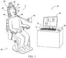
- FIG. 1 shows an exemplary IGS navigation system (10) enabling an ENT procedure to be performed using image guidance.
- IGS navigation system (10) may be constructed and operable in accordance with at least some of the teachings of U.S. Pat. No.
- IGS navigation system (10) of the present example comprises a field generator assembly (20), which comprises set of magnetic field generators (24) that are integrated into a horseshoe-shaped frame (22). Field generators (24) are operable to generate alternating magnetic fields of different frequencies around the head (H) of the patient (P) to produce a tracked area that the IGS navigation system (10) associates a coordinate system with.
- a navigation guidewire (40) is inserted into the head (H) of the patient (P) in this example.
- Navigation guidewire (40) may be a standalone device or may be positioned on an end effector or other location of a medical instrument such as a surgical cutting instrument or dilation instrument.
- frame (22) is mounted to a chair (30), with the patient (P) being seated in the chair (30) such that frame (22) is located adjacent to the head (H) of the patient (P).
- chair (30) and/or field generator assembly (20) may be configured and operable in accordance with at least some of the teachings of U.S. Pat. No. 10,561,370, entitled “Apparatus to Secure Field Generating Device to Chair,” issued February 18, 2020 .
- IGS navigation system (10) of the present example further comprises a processor (12), which controls field generators (24) and other elements of IGS navigation system (10).
- processor (12) is operable to drive field generators (24) to generate alternating electromagnetic fields; and process signals from navigation guidewire (40) to determine the location of a sensor in navigation guidewire (40) within the head (H) of the patient (P).
- Processor (12) comprises a processing unit (e.g., a set of electronic circuits arranged to evaluate and execute software instructions using combinational logic circuitry or other similar circuitry) communicating with one or more memories.
- Processor (12) of the present example is mounted in a console (18), which comprises operating controls (14) that include a keypad and/or a pointing device such as a mouse or trackball. A physician uses operating controls (14) to interact with processor (12) while performing the surgical procedure.
- Navigation guidewire (40) includes a sensor (not shown) that is responsive to positioning within the alternating magnetic fields generated by field generators (24), and that generates data usable to determine the position of the sensor within the magnetic fields.
- a coupling unit (42) is secured to the proximal end of navigation guidewire (40) and is configured to provide communication of data and other signals between console (18) and navigation guidewire (40). Coupling unit (42) may provide wired or wireless communication of data and other signals. While the position sensor is located in guidewire (40) in this example, such a position sensor may be integrated into various other kinds of instruments, such as dilation catheters, guide catheters, guide rails, suction instruments, pointer instruments, registration probes, curettes, patient trackers, and other instruments, including those described in greater detail below.
- Processor (12) uses software stored in a memory of processor (12) to calibrate and operate IGS navigation system (10). Such operation includes driving field generators (24), processing data from navigation guidewire (40), processing data from operating controls (14), and driving display screen (16). Processor (12) is further operable to provide video in real time via display screen (16), showing the position of the distal end of navigation guidewire (40) in relation to a video camera image of the patient's head (H), a CT scan image of the patient's head (H), and/or a computer generated three-dimensional model of the anatomy within and adjacent to the patient's nasal cavity. Display screen (16) may display such images simultaneously and/or superimposed on each other during the surgical procedure.
- Such displayed images may also include graphical representations of instruments that are inserted in the patient's head (H), such as navigation guidewire (40), such that the operator may view the virtual rendering of the instrument at its actual location in real time.
- display screen (16) may provide images in accordance with at least some of the teachings of U.S. Pat. No. 10,463,242, entitled “Guidewire Navigation for Sinuplasty,” issued November 5, 2019 .
- the endoscopic image may also be provided on display screen (16).
- Surgical instruments tracked by the IGS navigation system (10) may include a position sensor that reacts to an alternating magnetic field generated by field generator assembly (20) and thereby produces signals indicative of the position of the sensor within the field.
- a position sensor may be in communication with a connected device such as the coupling unit (42) or the processor (12) via one or more sensor wires that run from the sensor itself, along the length of the surgical instrument.
- the sensor wire may be positioned within a primary channel or on an exterior of the shaft of the instrument, and may couple to the position sensor at the tip of the instrument.
- an exterior sensor wire is damaged by another instrument (e.g., a drilling or cutting instrument used in conjunction), or that an interior sensor wire is damaged by instruments passing through the channel (e.g., a stylet used to clear a blockage in a suction instrument, a cutting instrument passing through a delivery catheter).
- another instrument e.g., a drilling or cutting instrument used in conjunction
- an interior sensor wire is damaged by instruments passing through the channel (e.g., a stylet used to clear a blockage in a suction instrument, a cutting instrument passing through a delivery catheter).
- FIG. 2 shows a perspective view of an exemplary suction instrument (100) with the path of an embedded position sensor wire indicated by a dotted line.
- the suction instrument (100) includes a grip (102) adapted to be held in the hand during use in a medical procedure, a shaft assembly (104) whose distal end may be inserted into the patient during use, and a tip (106) at the distal end of the shaft assembly (104) from which suction and/or irrigation may be provided when positioned near the surgical site.
- a hose connector (112) may be coupled to a suction and/or irrigation source via a hose or tube.
- Hose connector (112) provides access to a suction channel that runs through the shaft assembly (104) and terminates at the distal tip (106).
- a port (114) is positioned on the grip (102) and opens into the suction channel. When the port (114) is uncovered, suction from the hose connector (112) will draw suction to atmosphere primarily at the port (114) instead of drawing suction at the distal tip (106). When the port (114) is covered, the suction will be communicated to the distal tip (106). In this manner, a user can cover or uncover the port (114) (e.g., such as with a thumb or other finger when holding the grip (102)) in order to selectively apply suction at the surgical site.
- a cable (110) holds and protects portions of the sensor wire that are located outside of the suction instrument (100).
- the sensor wire (130) may be of a diameter much smaller than the cable (110) and may include a flexible rubber coating. After exiting the cable (110), the sensor wire (130) runs along a path within the suction instrument (100) illustrated as a dotted line in FIG. 1 .
- the shaft assembly (104) may also be shaped or flexed in varying ways in order to traverse anatomical passages and position the distal tip (106) at the surgical site. In both cases, it can be seen that, absent protection, a significant length of the sensor wire (130) may be subject to damage during blockage clearing or shaping.
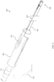
- FIG. 3 shows an exploded perspective view of the suction instrument (100).
- the grip (102) is separated into a first half (102a) and a second half (102b), which are adapted to hold a body (116) whose hollow interior defines the suction channel.
- the components of the shaft assembly (104) can be seen to include a shaft base (120), an outer shaft (122), and an inner tube (124).
- the inner tube (124) is of a diameter that allows it to snugly fit inside the outer shaft (122); and of a length similar to the outer shaft (122).
- the outer shaft (122) is of a diameter that allows it to snugly fit inside the shaft base (120), and the shaft base (120) itself is of a diameter that fits snugly within the distal suction channel opening (121) of the body (116).
- the sensor wire (130) can be seen protruding from the suction channel opening (121) and terminating at a position sensor (132) proximate to the distal end of the outer shaft (122).
- Position sensor (132) may include one or more coils that are configured to generate signals that indicate the location of position sensor (132) within three dimensional space (e.g., within the head (H) of the patient (P)), in response to alternating electromagnetic fields generated by field generators (24), like the position sensor in guidewire (40) as described above.
- the sensor wire (130) is immediately contained within an inner lumen (125) (shown in FIGS.
- the inner lumen (125) may be formed inside the inner tube (124) as part of a manufacturing process (e.g., an extrusion process), or may be a separate piece that is later coupled to the interior of the inner tube (124).
- the position sensor (132) is sized to fit within a sensor cover (126), and the sensor cover (126) itself is sized to fit within a slot at the distal end of the outer shaft (122), as will be illustrated in more detail below.
- the shaft base (120) may be formed of stainless steel (e.g., or another metal), and may be malleable or rigid, depending upon the length of the shaft assembly (104) that is desired to be shapeable.
- the shaft base (120) makes the proximal side of the shaft assembly (104) stiffer than the distal end to provide steerability of the tool during a surgical procedure.
- the outer shaft (122) may be formed of a malleable material such as stainless steel, while the inner tube (124) may be formed of a polymer or other flexible material such that it can be shaped by the outer shaft (122).
- the cover (126) may be formed of a rigid polymer, metal, or other material. Cover (126) may protect the sensor (132) from damage due to navigation or parallel use with other surgical tools (e.g., drills, debriders), while the material (e.g., stainless steel) of the outer shaft (122) protects the sensor wire (130) from the same.
- inner tube (124) may have a wall thickness of around 0.127mm (.005 inches), and may be comprised of a flexible material (e.g., Pebax 5333, Tecobax MPD-441-45D) that accommodates bending of the outer shaft (122) by a 6.35mm (.25 inch) or greater bend radius without kinking or otherwise damaging the sensor wire (130).
- a flexible material e.g., Pebax 5333, Tecobax MPD-441-45D
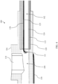
- FIG. 4 shows a cross sectional view of the body (116) of the suction instrument (100).
- the proximal ends of the shaft base (120), outer shaft (122), and inner tube (124) are visible coaxially nested within each other and within the distal end of the body (116).
- a portion of the sensor wire (130) can be seen running along the underside of the body (116), outside of the suction channel (109).
- the sensor wire (130) enters the suction channel (109) through a laterally facing hole (111) formed in the sidewall of the body (116), and immediately enters an inner lumen (125) that runs along an interior wall of the inner tube (124).
- the hole (111) and the inner lumen (125) may be positioned in order to minimize or completely eliminate any length of the sensor wire (130) that is exposed within the suction channel (109), in order to mitigate risks relating to use of a stylet or other tool to clear the suction channel (109) of blockages.
- the sensor wire (130) may be loosely positioned within the suction instrument (100), between the body (116) and the grip (102), with a distal end coupled to the position sensor (132) and an overall length that allows for some movement of the sensor wire (130) due to bending or shaping of the outer shaft (122)). This may allow the sensor wire to longitudinally shift or be pulled taught within the inner lumen (125) without breaking as a result of shaping.
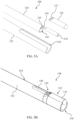
- FIG. 5A shows an exploded perspective view of the distal tip (106) of the suction instrument (100).
- the sensor wire (130) can be seen exiting the distal end of the inner lumen (125) and coupling to the sensor (132).
- the sensor cover (126) is ball shaped at the distal end to make it a ball tip or ball point suction instrument (100), though other shapes may be used as well.
- the sensor cover (126) includes an opening sized to receive the sensor (132), which may be loosely fit, friction fit, or fixed within the cover (126) by an adhesive or other coupling element or material.
- the cover (126) is also sized to fit within a transverse slot (144) in the distal end of the outer shaft (122), as can be seen in the fully assembled distal tip (106) of FIG. 5B .
- the senor (132) is contained within the sensor cover (126), and a small portion of the sensor wire (130) can be seen extending from the sensor cover (126) and entering the inner lumen (125).
- the sensor cover (126) is positioned within the slot (144) just above a distal opening (136) of the outer shaft (122), and substantially or completely fills the distal end of the slot (144) so that the opening (136) is unbroken and capable of delivering focused suction and/or irrigation.
- the sensor cover (126) has a bevel (127) at the proximal end of sensor cover (126), which may provide a substantially smooth transition at the exterior of shaft assembly (104) while also protecting the inner side of the portion of sensor wire (130) passing through slot (144), as best seen in FIG, 5C .
- a cover seal (134) is wrapped around the distal tip (106), and in some implementations may extend along some or all of the remainder of the shaft assembly (104).
- the cover seal (134) may be, for example, a polymer heat wrap coating that is loosely placed on the distal tip (106) and then heated to cause shrinkage and a tight fit and seal, or may be a sealant or coating that is applied and that dries or cures in order to hold the components of the distal tip (106) in place and seal gaps.
- the cover seal (134) substantially covers the sensor cover (126) and descends along its bevel (127) to the outer shaft (122), where it entirely covers the slot (144) in order to concentrate suction at the distal opening (136) and prevent suction loss via the slot (144).
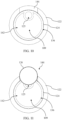
- FIG. 5C shows a cross-sectional view of the assembled distal tip (106) of FIG. 5B .
- the cover seal (134) is visible on the exterior edge of the assembly, holding the sensor cover (126) within the slot (144).
- the edge of the slot (144) may be sized to receive and hold the sensor cover (126) while preventing sensor cover (126) from completely passing through the slot (144), such that application of the cover seal (134) couples the pieces together and prevents shifting.
- the cover seal (134) extends down the bevel (127) of the sensor cover (126) and covers the entirety of the shaft (144), resulting in a small space between distal opening of the inner lumen (125) and the opening of the sensor cover (126) that the control wire (130) loosely spans, allowing for movement or flexing of the sensor wire (130) as a result of bending of the shaft assembly (104).
- the inner lumen (125) may be sealed at one or both openings or may be left open.
- the sensor wire (130) may substantially fill the interior of the inner lumen (125), such that the effects of any suction or irrigation on the inner lumen (125) are negligible.
- the sensor cover (126) and inner lumen (125) may be sized and shaped to minimize or eliminate any portion of the control wire (130) that is exposed to the suction channel (109), such as is shown in FIG. 5C .
- a stylet or other channel clearing tool passing through the suction channel (109) in either direction will be diverted from contact with the sensor wire (130) by the edge or underside of the inner lumen (130), or the underside of the sensor cover (126).
- FIG. 6 shows a perspective view of the inner tube (124) with the sensor wire (130) extending from the inner lumen (125) and connecting to the position sensor (132). With the outer shaft (122) and sensor cover (126) removed, the inner lumen (125) that holds the sensor wire (130) is visible, as well as the primary lumen (142) that defines the suction channel (109) at the distal tip (106).
- FIG. 7 shows an elevation view looking down the inner tube (124).
- the inner lumen (125) is coupled to or formed onto an interior wall of the primary lumen (142), and it can be seen that the majority of the of inner tube's (124) interior is unobstructed to allow for sufficient suction flow.
- the inner tube (124) shown in FIG. 7 and elsewhere shows the inner lumen (125) as being continuously positioned on an upper interior wall of the inner tube (124), some implementations may include an inner lumen that is positioned elsewhere (e.g., on a sidewall or bottom wall), or may include an inner lumen that runs along the interior walls of the inner tube (124) non-linearly so that it twists along the interior of the shaft.
- an origin position (123) for the inner lumen (125) is illustrated in FIG. 7 .
- the proximal opening of the inner lumen is located as illustrated in FIG. 7 , the span of control wire exposed to the suction channel (109) after entering the body (116) would be further minimized (e.g., with reference to FIG.
- the span of control wire (130) between the hole (111) and the opening of the inner lumen (125) would be further minimized).
- the rate of twist of the inner lumen (125) position could be selected such that it could be positioned proximate to an opening on the sidewall of the body, and then gradually twist along the shaft until it is just below the slot (144) at the distal tip (106).
- FIG. 8 shows a perspective view of the outer shaft (122) and the slot (144) With the sensor cover (126) removed, the slot (144) can be seen extending from the distal opening (136) and down part of the length of the outer shaft (122) to a distance that allows for the slot (144) to receive the sensor cover (126), and allows for the sensor wire (130) to exit the inner lumen (125) and pass through the slot (144) to enter the sensor cover (126).
- FIG. 9 shows an elevation view looking down the outer shaft (122).
- the width of the slot (144) may be such that the full diameter of the sensor cover (126) cannot pass completely through the slot (144), as has been described. In other words, the outer diameter of sensor cover (126) is greater than the width of slot (144).
- FIG. 10 shows an elevation view looking down the assembled inner tube (124) and outer shaft (122), with the inner lumen (125) aligned with the slot (144) and the primary lumen (142) feeding into the distal opening (136) of the outer shaft (122).
- FIG. 11 shows an assembled distal tip (106), with the sensor cover (126) installed within the slot (144), and aligned with the inner lumen (125). With the seal cover (134) installed, as shown in FIG. 5B and 5C , the suction channel within the shaft assembly (104) is unbroken such that the resulting suction is focused at the distal opening (136).
- the distal opening (136) itself is unbroken, which allows for strong suction when the distal opening (136) contacts materials or fluids. It should also be appreciated that the sensor cover (126) does not substantially obstruct the primary lumen (142) or the distal opening (136) (e.g., only about 10% or less of the circular area of the distal opening (136) is occupied, while varying implementations may occupy between about 5% and about 25% of the opening).
- position sensor (132) is oriented along an axis that is parallel with yet slightly axially offset from the central longitudinal axis of shafts (122, 124). The distance of this lateral offset may be predetermined and fixed. Thus, processor (12) may readily calculate the precise location of distal opening (136) in three-dimensional space based on position-indicative signals that are generated by position sensor (132).
- Another advantage of the sensor cover (126) being at the distal end of the suction instrument (100) is that it provides a visible reference point for a user of the suction instrument (100). As an example, the sensor cover (126) can be seen to have a convex shape that extends from the slot (144) as a ball point.
- This ball point shape provides a visible reference point that indicates the location and orientation of the suction instrument (100) when viewed directly or via an endoscope or other camera, or when viewed via an IGS display with a crosshair, illuminated dot, or some other visual indicator overlaid upon the ball point.
- suction instrument (100) and suction instruments generally as being advantageously implemented with a protected sensor wire
- the structures and features disclosed herein may be advantageously implemented in a variety of surgical instruments or other medical instruments that include a shaft and distally mounted position sensor.
- instruments such as a catheter (e.g., a fixed, articulated, or malleable catheter) used to guide other instruments to a surgical site, shaver instruments, dilation catheters, and various other kinds of instruments as will be apparent to those skilled in the art in view of the teachings herein may implement a flexible inner lumen that protects the sensor wire without obstructing the delivery channel.
- the first point may be the virtual camera's orientation. This may be advantageous where a clinician has determined a position within the surgical area that is of interest and wishes to select that as the point of orientation (i.e., the second point), then preview a number of camera positions (e.g., the first point) using the real-time virtual endoscopic preview and relational flythrough before making a selection.
- Choosing the virtual camera's location as the first point may be advantageous where a clinician may use their experience to first determine the best location for the virtual camera, and then may use the real-time virtual endoscopic preview and relational flythrough to choose a point of the surgical area that they would like to focus the virtual camera upon.
- Versions of the devices disclosed herein can be designed to be disposed of after a single use, or they can be designed to be used multiple times. Versions may, in either or both cases, be reconditioned for reuse after at least one use. Reconditioning may include any combination of the steps of disassembly of the device, followed by cleaning or replacement of particular pieces, and subsequent reassembly. In particular, versions of the device may be disassembled, and any number of the particular pieces or parts of the device may be selectively replaced or removed in any combination. Upon cleaning and/or replacement of particular parts, versions of the device may be reassembled for subsequent use either at a reconditioning facility, or by a surgical team immediately prior to a surgical procedure.
- reconditioning of a device may utilize a variety of techniques for disassembly, cleaning/replacement, and reassembly. Use of such techniques, and the resulting reconditioned device, are all within the scope of the present application.
- versions described herein may be processed before surgery.
- a new or used instrument may be obtained and if necessary cleaned.
- the instrument may then be sterilized.
- the instrument is placed in a closed and sealed container, such as a plastic or TYVEK bag.
- the container and instrument may then be placed in a field of radiation that can penetrate the container, such as gamma radiation, x-rays, or high-energy electrons.
- the radiation may kill bacteria on the instrument and in the container.
- the sterilized instrument may then be stored in the sterile container.
- the sealed container may keep the instrument sterile until it is opened in a surgical facility.
- a device may also be sterilized using any other technique known in the art, including but not limited to beta or gamma radiation, ethylene oxide, or steam.
Landscapes
- Health & Medical Sciences (AREA)
- Heart & Thoracic Surgery (AREA)
- Life Sciences & Earth Sciences (AREA)
- Engineering & Computer Science (AREA)
- General Health & Medical Sciences (AREA)
- Biomedical Technology (AREA)
- Animal Behavior & Ethology (AREA)
- Public Health (AREA)
- Veterinary Medicine (AREA)
- Surgery (AREA)
- Hematology (AREA)
- Anesthesiology (AREA)
- Vascular Medicine (AREA)
- Medical Informatics (AREA)
- Nuclear Medicine, Radiotherapy & Molecular Imaging (AREA)
- Molecular Biology (AREA)
- Pulmonology (AREA)
- Robotics (AREA)
- Oral & Maxillofacial Surgery (AREA)
- Otolaryngology (AREA)
- Dentistry (AREA)
- Endoscopes (AREA)
- Media Introduction/Drainage Providing Device (AREA)
- Threshing Machine Elements (AREA)
- Sampling And Sample Adjustment (AREA)
- Accommodation For Nursing Or Treatment Tables (AREA)
- Surgical Instruments (AREA)
Claims (15)
- Vorrichtung, umfassend:(a) eine Schaftbaugruppe (104), die Folgendes aufweist:(i) einen äußeren Schaft (122) mit einer distalen Öffnung (136) und einem Schlitz (144) an der distalen Öffnung (136),(ii) ein inneres Rohr (124), das in dem äußeren Schaft (122) angeordnet ist, wobei eine distale Öffnung des inneren Rohrs (124) in Längsrichtung von der distalen Öffnung (136) des äußeren Schafts (122) versetzt und auf den Schlitz (144) ausgerichtet ist, und(iii) ein inneres Lumen (125), das an einer Innenwand des inneren Rohrs (124) positioniert ist,(b) einen Positionssensor (132) undeinen Sensordraht (130), der zum Übertragen von Signalen von dem Positionssensor (132) ausgestaltet ist, wobei der Sensordraht (130):(i) in dem inneren Lumen (125) enthalten und von dem Innenraum des inneren Rohrs (124) isoliert ist und(ii) über eine distale Öffnung des inneren Lumens (125) aus dem inneren Lumen (125) austritt, durch den Schlitz (144) geht und mit dem Positionssensor (132) koppelt.
- Vorrichtung nach Anspruch 1, ferner umfassend:(a) einen Körper (116), wobei sich die Schaftbaugruppe (104) distal von dem Körper (116) erstreckt, und(b) eine Sensorabdeckung (126), die den Positionssensor (132) enthält und in dem Schlitz (144) in der Nähe der distalen Öffnung des inneren Lumens (125) positioniert ist, wobei der Sensordraht (130) in die Sensorabdeckung (126) eintritt, um mit dem Positionssensor (132) zu koppeln.
- Vorrichtung nach Anspruch 2, ferner umfassend eine Schaftabdeckung (134), die die Sensorabdeckung (126) und den äußeren Schaft (122) umgibt, um etwaige Lücken abzudichten, wo die Sensorabdeckung (126) auf den äußeren Schaft (122) trifft, und zur Abdichtung etwaiger offener Abschnitte des Schlitzes (144), optional wobei die Schaftabdeckung eine Wärmeschutzabdeckung aufweist, die dazu ausgeführt ist, lose an die Sensorabdeckung (126) und den äußeren Schaft (122) zu passen und dann durch eine Wärmebehandlung dicht abgedichtet zu werden.
- Vorrichtung nach Anspruch 1 oder Anspruch 2, wobei die Sensorabdeckung (126):(i) einen Großteil der distalen Öffnung des inneren Lumens (125) versperrt und(ii) weniger als ungefähr 15 % des kreisförmigen Bereichs der distalen Öffnung des äußeren Schafts (122) blockiert.
- Vorrichtung nach Anspruch 2, wobei der Sensordraht (130) dazu ausgestaltet ist, innerhalb des inneren Lumens (130) zu translatieren, während er noch mit dem Positionssensor (132) gekoppelt ist.
- Vorrichtung nach Anspruch 1 oder Anspruch 2, wobei sich das innere Lumen (125) entlang des Innenraums des inneren Rohrs (124) so verdreht, dass:(i) eine proximale Öffnung des inneren Lumens (125) an einer inneren Seitenwand des inneren Rohrs (124) positioniert ist und(ii) die distale Öffnung des inneren Lumens (125) an einer inneren Oberseite des inneren Rohrs (124) positioniert ist.
- Vorrichtung nach Anspruch 2, wobei der äußere Schaft (122) aus einem verformbaren Material und das innere Rohr (124) aus einem flexiblen Material besteht, optional wobei:(i) das verformbare Material des äußeren Schafts (122) einen rostfreien Stahl umfasst und(ii) das flexible Material des inneren Rohrs (124) ein Polymer umfasst.
- Vorrichtung nach Anspruch 2, wobei die Sensorabdeckung (126) einen Durchmesser aufweist, wobei der Schlitz eine Breite (144) aufweist und wobei der Durchmesser der Sensorabdeckung (126) die Breite des Schlitzes (144) überschreitet, so dass die Sensorabdeckung (126) die volle Breite des Schlitzes (144) einnimmt.
- Vorrichtung nach Anspruch 2, wobei die Längsachse der Sensorabdeckung (126) von der Längsachse des inneren Lumens (125) versetzt ist und wobei sich ein Abschnitt des Sensordrahts (130) in einem Winkel biegt, damit sich der Sensordraht (130) zwischen dem inneren Lumen (125) und der versetzten Sensorabdeckung (126) erstreckt.
- Vorrichtung nach Anspruch 2, wobei ein Durchmesser des Sensordrahts (130) im Wesentlichen einen Durchmesser des inneren Lumens (125) einnimmt.
- Vorrichtung nach Anspruch 2, wobei der Positionssensor (132) mindestens eine Spule aufweist, die zur Erzeugung von Positionsdaten basierend auf Wechselwirkungen mit einem magnetischen Wechselfeld und zur Übertragung der Positionsdaten über den Sensordraht (132) ausgestaltet ist.
- Vorrichtung nach Anspruch 2, wobei eine Öffnung der Sensorabdeckung (126) derart abgewinkelt ist, dass sich ein proximaler Rand der Sensorabdeckung (126) von dem äußeren Schaft (122) in einem Winkel von weniger als 90 Grad nach oben erstreckt.
- Vorrichtung nach Anspruch 2, wobei der Körper einen Längskanal umfasst, der an einer distalen Kanalöffnung (121) endet, und die Schaftbaugruppe (104) in der distalen Kanalöffnung (121) positioniert und an den Körper (116) gekoppelt ist.
- Vorrichtung nach Anspruch 2, wobei der Sensordraht (132) :(i) in den Körper (116) durch ein Loch in dem Körper (116) eintritt, das sich in der Nähe einer proximalen Öffnung des inneren Lumens (125) befindet, und(ii) über die proximale Öffnung des inneren Lumens (125) in das innere Lumen (125) eintritt.
- Verfahren zum Zusammenbau eines Sauginstruments (100), umfassend:(a) Koppeln einer Schaftbaugruppe (104) mit einem Körper (116), wobei die Schaftbaugruppe (104) Folgendes aufweist:(i) einen äußeren Schaft (122), wobei der äußere Schaft (122) eine distale Öffnung (136) und einen seitlichen Schlitz (144) aufweist, der sich proximal von der distalen Öffnung (136) erstreckt,(ii) ein inneres Rohr (124), das in dem äußeren Schaft (122) positioniert ist, wobei eine distale Öffnung des inneren Rohrs (124) in Längsrichtung von der distalen Öffnung des äußeren Schafts (122) versetzt ist, und(iii) ein inneres Lumen (125), das an einer Innenwand des inneren Rohrs (124) positioniert ist,(b) Einführen eines Positionssensors (132) in eine Sensorabdeckung (126),(c) Einführen der Sensorabdeckung (126) in den Schlitz (144) in der Nähe einer distalen Öffnung des inneren Lumens (125) und(d) Verlegen eines Sensordrahts (130) durch das innere Lumen (125), wobei der Sensordraht (130) mit dem Positionssensor (132) gekoppelt und zum Übertragen von Signalen von dem Positionssensor (132) ausgestaltet ist.
Applications Claiming Priority (3)
| Application Number | Priority Date | Filing Date | Title |
|---|---|---|---|
| US202063023486P | 2020-05-12 | 2020-05-12 | |
| US17/239,762 US12042233B2 (en) | 2020-05-12 | 2021-04-26 | Malleable suction instrument with offset position sensor |
| PCT/IB2021/053741 WO2021229363A1 (en) | 2020-05-12 | 2021-05-04 | Malleable suction instrument with offset position sensor |
Publications (3)
| Publication Number | Publication Date |
|---|---|
| EP4149381A1 EP4149381A1 (de) | 2023-03-22 |
| EP4149381C0 EP4149381C0 (de) | 2024-11-13 |
| EP4149381B1 true EP4149381B1 (de) | 2024-11-13 |
Family
ID=78513640
Family Applications (1)
| Application Number | Title | Priority Date | Filing Date |
|---|---|---|---|
| EP21724781.6A Active EP4149381B1 (de) | 2020-05-12 | 2021-05-04 | Verformbares sauginstrument mit versetztem positionssensor |
Country Status (6)
| Country | Link |
|---|---|
| US (2) | US12042233B2 (de) |
| EP (1) | EP4149381B1 (de) |
| JP (1) | JP7714580B2 (de) |
| CN (1) | CN115605156A (de) |
| IL (1) | IL297870B2 (de) |
| WO (1) | WO2021229363A1 (de) |
Families Citing this family (4)
| Publication number | Priority date | Publication date | Assignee | Title |
|---|---|---|---|---|
| US20210386445A1 (en) * | 2020-06-10 | 2021-12-16 | John H. Burban | Nasal smoke evacuator |
| WO2024228065A1 (en) * | 2023-05-02 | 2024-11-07 | Acclarent, Inc. | Medical instrument position sensor sleeve with integral heating element |
| KR200497952Y1 (ko) * | 2023-08-02 | 2024-04-23 | 이신형 | 확장캡을 포함하는 석션팁 |
| EP4523645A1 (de) * | 2023-09-14 | 2025-03-19 | Stryker European Operations Limited | Chirurgische schlauchanordnung und chirurgisches instrument mit der schlauchanordnung |
Family Cites Families (22)
| Publication number | Priority date | Publication date | Assignee | Title |
|---|---|---|---|---|
| US4329994A (en) * | 1980-06-18 | 1982-05-18 | American Hospital Supply Corporation | Multilumen catheter |
| US7670327B2 (en) | 2000-01-20 | 2010-03-02 | Regents Of The University Of Minnesota | Catheter systems for delivery of agents and related method thereof |
| US6626902B1 (en) | 2000-04-12 | 2003-09-30 | University Of Virginia Patent Foundation | Multi-probe system |
| US7291127B2 (en) * | 2003-07-28 | 2007-11-06 | Boston Scientific Scimed, Inc. | Variable manipulative strength catheter |
| US20070208252A1 (en) | 2004-04-21 | 2007-09-06 | Acclarent, Inc. | Systems and methods for performing image guided procedures within the ear, nose, throat and paranasal sinuses |
| US7720521B2 (en) | 2004-04-21 | 2010-05-18 | Acclarent, Inc. | Methods and devices for performing procedures within the ear, nose, throat and paranasal sinuses |
| WO2008111070A2 (en) | 2007-03-12 | 2008-09-18 | David Tolkowsky | Devices and methods for performing medical procedures in tree-like luminal structures |
| US9452276B2 (en) | 2011-10-14 | 2016-09-27 | Intuitive Surgical Operations, Inc. | Catheter with removable vision probe |
| US9913585B2 (en) * | 2014-01-15 | 2018-03-13 | Medtronic Vascular, Inc. | Catheter for providing vascular pressure measurements |
| US10463242B2 (en) | 2014-07-09 | 2019-11-05 | Acclarent, Inc. | Guidewire navigation for sinuplasty |
| US10362965B2 (en) | 2015-04-22 | 2019-07-30 | Acclarent, Inc. | System and method to map structures of nasal cavity |
| US10111715B2 (en) | 2015-05-11 | 2018-10-30 | Veran Medical Technologies, Inc. | Adjustable length medical instrument assembly with localization elements for tracking medical instrument extension |
| DE202016104966U1 (de) | 2015-09-14 | 2016-12-12 | Scopis Gmbh | Befestigung von Sensoren an chirurgischen Instrumenten |
| JP2017176719A (ja) * | 2016-03-31 | 2017-10-05 | 日本ゼオン株式会社 | カテーテル |
| US20180085174A1 (en) | 2016-09-23 | 2018-03-29 | Acclarent, Inc. | Suction device for use in image-guided sinus medical procedure |
| CN108618769B (zh) * | 2017-03-15 | 2021-01-15 | 深圳北芯生命科技有限公司 | 带安装座的血管内压力测量导管 |
| US10561370B2 (en) | 2017-04-26 | 2020-02-18 | Accalrent, Inc. | Apparatus to secure field generating device to chair |
| US11253677B2 (en) * | 2017-05-31 | 2022-02-22 | Acclarent, Inc. | Navigable suction instrument with coaxial annular sensor |
| EP3634216A1 (de) | 2017-06-02 | 2020-04-15 | Boston Scientific Scimed Inc. | Kontrastentfernungssystem |
| US11523942B2 (en) | 2017-08-10 | 2022-12-13 | Biosense Webster (Israel) Ltd. | Medical suction tool for a Eustachian tube |
| US10736647B2 (en) | 2017-10-30 | 2020-08-11 | Acclarent, Inc. | Dilation catheter with navigation sensor and vent passageway in tip |
| US20200107726A1 (en) | 2018-10-05 | 2020-04-09 | Acclarent, Inc. | Suction instrument with dissecting tip and axially offset sensors |
-
2021
- 2021-04-26 US US17/239,762 patent/US12042233B2/en active Active
- 2021-05-04 JP JP2022568824A patent/JP7714580B2/ja active Active
- 2021-05-04 WO PCT/IB2021/053741 patent/WO2021229363A1/en not_active Ceased
- 2021-05-04 EP EP21724781.6A patent/EP4149381B1/de active Active
- 2021-05-04 CN CN202180034646.XA patent/CN115605156A/zh active Pending
- 2021-05-04 IL IL297870A patent/IL297870B2/en unknown
-
2024
- 2024-07-22 US US18/780,374 patent/US20240374323A1/en active Pending
Also Published As
| Publication number | Publication date |
|---|---|
| US12042233B2 (en) | 2024-07-23 |
| IL297870B2 (en) | 2025-08-01 |
| EP4149381A1 (de) | 2023-03-22 |
| JP7714580B2 (ja) | 2025-07-29 |
| US20210353363A1 (en) | 2021-11-18 |
| WO2021229363A1 (en) | 2021-11-18 |
| JP2023526260A (ja) | 2023-06-21 |
| IL297870A (en) | 2023-01-01 |
| US20240374323A1 (en) | 2024-11-14 |
| EP4149381C0 (de) | 2024-11-13 |
| IL297870B1 (en) | 2025-04-01 |
| CN115605156A (zh) | 2023-01-13 |
Similar Documents
| Publication | Publication Date | Title |
|---|---|---|
| EP4149381B1 (de) | Verformbares sauginstrument mit versetztem positionssensor | |
| EP3367932B1 (de) | System zur navigation chirurgischer instrumente | |
| JP7574350B2 (ja) | 同軸環状センサを備えたナビゲート可能な吸引器具 | |
| JP7551830B2 (ja) | ナビゲーションセンサを備えたキュレット | |
| US20190374129A1 (en) | Endoscope with integral navigation sensor | |
| US10959785B2 (en) | Tissue shaving instrument with navigation sensor | |
| CA3034938A1 (en) | Medical instrument with self-collapsing channel | |
| US20240050720A1 (en) | Dilation Instrument with Malleable Guide and Dilation Catheter with Integral Position Sensor | |
| US11998284B2 (en) | Articulating guide with integral position sensor | |
| US20200107726A1 (en) | Suction instrument with dissecting tip and axially offset sensors | |
| US12588954B2 (en) | Articulating guide with integral position sensor | |
| WO2024231744A1 (en) | Medical instrument with rotary end effector, position sensor, and electromagnetic interference reduction |
Legal Events
| Date | Code | Title | Description |
|---|---|---|---|
| STAA | Information on the status of an ep patent application or granted ep patent |
Free format text: STATUS: UNKNOWN |
|
| STAA | Information on the status of an ep patent application or granted ep patent |
Free format text: STATUS: THE INTERNATIONAL PUBLICATION HAS BEEN MADE |
|
| PUAI | Public reference made under article 153(3) epc to a published international application that has entered the european phase |
Free format text: ORIGINAL CODE: 0009012 |
|
| STAA | Information on the status of an ep patent application or granted ep patent |
Free format text: STATUS: REQUEST FOR EXAMINATION WAS MADE |
|
| 17P | Request for examination filed |
Effective date: 20221209 |
|
| AK | Designated contracting states |
Kind code of ref document: A1 Designated state(s): AL AT BE BG CH CY CZ DE DK EE ES FI FR GB GR HR HU IE IS IT LI LT LU LV MC MK MT NL NO PL PT RO RS SE SI SK SM TR |
|
| DAV | Request for validation of the european patent (deleted) | ||
| DAX | Request for extension of the european patent (deleted) | ||
| GRAP | Despatch of communication of intention to grant a patent |
Free format text: ORIGINAL CODE: EPIDOSNIGR1 |
|
| STAA | Information on the status of an ep patent application or granted ep patent |
Free format text: STATUS: GRANT OF PATENT IS INTENDED |
|
| RIC1 | Information provided on ipc code assigned before grant |
Ipc: A61M 1/00 20060101ALI20240716BHEP Ipc: A61B 17/24 20060101ALI20240716BHEP Ipc: A61B 34/20 20160101AFI20240716BHEP |
|
| INTG | Intention to grant announced |
Effective date: 20240802 |
|
| GRAS | Grant fee paid |
Free format text: ORIGINAL CODE: EPIDOSNIGR3 |
|
| GRAA | (expected) grant |
Free format text: ORIGINAL CODE: 0009210 |
|
| STAA | Information on the status of an ep patent application or granted ep patent |
Free format text: STATUS: THE PATENT HAS BEEN GRANTED |
|
| AK | Designated contracting states |
Kind code of ref document: B1 Designated state(s): AL AT BE BG CH CY CZ DE DK EE ES FI FR GB GR HR HU IE IS IT LI LT LU LV MC MK MT NL NO PL PT RO RS SE SI SK SM TR |
|
| REG | Reference to a national code |
Ref country code: GB Ref legal event code: FG4D |
|
| REG | Reference to a national code |
Ref country code: CH Ref legal event code: EP |
|
| REG | Reference to a national code |
Ref country code: IE Ref legal event code: FG4D |
|
| REG | Reference to a national code |
Ref country code: DE Ref legal event code: R096 Ref document number: 602021021787 Country of ref document: DE |
|
| U01 | Request for unitary effect filed |
Effective date: 20241205 |
|
| U07 | Unitary effect registered |
Designated state(s): AT BE BG DE DK EE FI FR IT LT LU LV MT NL PT RO SE SI Effective date: 20241216 |
|
| PG25 | Lapsed in a contracting state [announced via postgrant information from national office to epo] |
Ref country code: IS Free format text: LAPSE BECAUSE OF FAILURE TO SUBMIT A TRANSLATION OF THE DESCRIPTION OR TO PAY THE FEE WITHIN THE PRESCRIBED TIME-LIMIT Effective date: 20250313 Ref country code: HR Free format text: LAPSE BECAUSE OF FAILURE TO SUBMIT A TRANSLATION OF THE DESCRIPTION OR TO PAY THE FEE WITHIN THE PRESCRIBED TIME-LIMIT Effective date: 20241113 |
|
| PG25 | Lapsed in a contracting state [announced via postgrant information from national office to epo] |
Ref country code: ES Free format text: LAPSE BECAUSE OF FAILURE TO SUBMIT A TRANSLATION OF THE DESCRIPTION OR TO PAY THE FEE WITHIN THE PRESCRIBED TIME-LIMIT Effective date: 20241113 |
|
| PG25 | Lapsed in a contracting state [announced via postgrant information from national office to epo] |
Ref country code: NO Free format text: LAPSE BECAUSE OF FAILURE TO SUBMIT A TRANSLATION OF THE DESCRIPTION OR TO PAY THE FEE WITHIN THE PRESCRIBED TIME-LIMIT Effective date: 20250213 |
|
| PG25 | Lapsed in a contracting state [announced via postgrant information from national office to epo] |
Ref country code: GR Free format text: LAPSE BECAUSE OF FAILURE TO SUBMIT A TRANSLATION OF THE DESCRIPTION OR TO PAY THE FEE WITHIN THE PRESCRIBED TIME-LIMIT Effective date: 20250214 |
|
| PG25 | Lapsed in a contracting state [announced via postgrant information from national office to epo] |
Ref country code: PL Free format text: LAPSE BECAUSE OF FAILURE TO SUBMIT A TRANSLATION OF THE DESCRIPTION OR TO PAY THE FEE WITHIN THE PRESCRIBED TIME-LIMIT Effective date: 20241113 |
|
| PGFP | Annual fee paid to national office [announced via postgrant information from national office to epo] |
Ref country code: GB Payment date: 20250313 Year of fee payment: 5 |
|
| PG25 | Lapsed in a contracting state [announced via postgrant information from national office to epo] |
Ref country code: RS Free format text: LAPSE BECAUSE OF FAILURE TO SUBMIT A TRANSLATION OF THE DESCRIPTION OR TO PAY THE FEE WITHIN THE PRESCRIBED TIME-LIMIT Effective date: 20250213 |
|
| U20 | Renewal fee for the european patent with unitary effect paid |
Year of fee payment: 5 Effective date: 20250407 |
|
| PG25 | Lapsed in a contracting state [announced via postgrant information from national office to epo] |
Ref country code: SM Free format text: LAPSE BECAUSE OF FAILURE TO SUBMIT A TRANSLATION OF THE DESCRIPTION OR TO PAY THE FEE WITHIN THE PRESCRIBED TIME-LIMIT Effective date: 20241113 |
|
| PG25 | Lapsed in a contracting state [announced via postgrant information from national office to epo] |
Ref country code: SK Free format text: LAPSE BECAUSE OF FAILURE TO SUBMIT A TRANSLATION OF THE DESCRIPTION OR TO PAY THE FEE WITHIN THE PRESCRIBED TIME-LIMIT Effective date: 20241113 |
|
| PG25 | Lapsed in a contracting state [announced via postgrant information from national office to epo] |
Ref country code: CZ Free format text: LAPSE BECAUSE OF FAILURE TO SUBMIT A TRANSLATION OF THE DESCRIPTION OR TO PAY THE FEE WITHIN THE PRESCRIBED TIME-LIMIT Effective date: 20241113 |
|
| PLBE | No opposition filed within time limit |
Free format text: ORIGINAL CODE: 0009261 |
|
| STAA | Information on the status of an ep patent application or granted ep patent |
Free format text: STATUS: NO OPPOSITION FILED WITHIN TIME LIMIT |
|
| 26N | No opposition filed |
Effective date: 20250814 |
|
| REG | Reference to a national code |
Ref country code: CH Ref legal event code: H13 Free format text: ST27 STATUS EVENT CODE: U-0-0-H10-H13 (AS PROVIDED BY THE NATIONAL OFFICE) Effective date: 20251223 |
|
| PG25 | Lapsed in a contracting state [announced via postgrant information from national office to epo] |
Ref country code: CH Free format text: LAPSE BECAUSE OF NON-PAYMENT OF DUE FEES Effective date: 20250531 |
|
| PG25 | Lapsed in a contracting state [announced via postgrant information from national office to epo] |
Ref country code: MC Free format text: LAPSE BECAUSE OF FAILURE TO SUBMIT A TRANSLATION OF THE DESCRIPTION OR TO PAY THE FEE WITHIN THE PRESCRIBED TIME-LIMIT Effective date: 20241113 |