EP4148980B1 - Dachhaken - Google Patents
Dachhaken Download PDFInfo
- Publication number
- EP4148980B1 EP4148980B1 EP22195172.6A EP22195172A EP4148980B1 EP 4148980 B1 EP4148980 B1 EP 4148980B1 EP 22195172 A EP22195172 A EP 22195172A EP 4148980 B1 EP4148980 B1 EP 4148980B1
- Authority
- EP
- European Patent Office
- Prior art keywords
- mounting
- shaped body
- toothing
- tile
- locking
- Prior art date
- Legal status (The legal status is an assumption and is not a legal conclusion. Google has not performed a legal analysis and makes no representation as to the accuracy of the status listed.)
- Active
Links
Images

Classifications
-
- H—ELECTRICITY
- H02—GENERATION; CONVERSION OR DISTRIBUTION OF ELECTRIC POWER
- H02S—GENERATION OF ELECTRIC POWER BY CONVERSION OF INFRARED RADIATION, VISIBLE LIGHT OR ULTRAVIOLET LIGHT, e.g. USING PHOTOVOLTAIC [PV] MODULES
- H02S20/00—Supporting structures for PV modules
- H02S20/20—Supporting structures directly fixed to an immovable object
- H02S20/22—Supporting structures directly fixed to an immovable object specially adapted for buildings
- H02S20/23—Supporting structures directly fixed to an immovable object specially adapted for buildings specially adapted for roof structures
-
- F—MECHANICAL ENGINEERING; LIGHTING; HEATING; WEAPONS; BLASTING
- F24—HEATING; RANGES; VENTILATING
- F24S—SOLAR HEAT COLLECTORS; SOLAR HEAT SYSTEMS
- F24S25/00—Arrangement of stationary mountings or supports for solar heat collector modules
- F24S25/60—Fixation means, e.g. fasteners, specially adapted for supporting solar heat collector modules
- F24S25/61—Fixation means, e.g. fasteners, specially adapted for supporting solar heat collector modules for fixing to the ground or to building structures
- F24S25/613—Fixation means, e.g. fasteners, specially adapted for supporting solar heat collector modules for fixing to the ground or to building structures in the form of bent strips or assemblies of strips; Hook-like connectors; Connectors to be mounted between building-covering elements
-
- F—MECHANICAL ENGINEERING; LIGHTING; HEATING; WEAPONS; BLASTING
- F24—HEATING; RANGES; VENTILATING
- F24S—SOLAR HEAT COLLECTORS; SOLAR HEAT SYSTEMS
- F24S25/00—Arrangement of stationary mountings or supports for solar heat collector modules
- F24S25/70—Arrangement of stationary mountings or supports for solar heat collector modules with means for adjusting the final position or orientation of supporting elements in relation to each other or to a mounting surface; with means for compensating mounting tolerances
-
- Y—GENERAL TAGGING OF NEW TECHNOLOGICAL DEVELOPMENTS; GENERAL TAGGING OF CROSS-SECTIONAL TECHNOLOGIES SPANNING OVER SEVERAL SECTIONS OF THE IPC; TECHNICAL SUBJECTS COVERED BY FORMER USPC CROSS-REFERENCE ART COLLECTIONS [XRACs] AND DIGESTS
- Y02—TECHNOLOGIES OR APPLICATIONS FOR MITIGATION OR ADAPTATION AGAINST CLIMATE CHANGE
- Y02B—CLIMATE CHANGE MITIGATION TECHNOLOGIES RELATED TO BUILDINGS, e.g. HOUSING, HOUSE APPLIANCES OR RELATED END-USER APPLICATIONS
- Y02B10/00—Integration of renewable energy sources in buildings
- Y02B10/20—Solar thermal
-
- Y—GENERAL TAGGING OF NEW TECHNOLOGICAL DEVELOPMENTS; GENERAL TAGGING OF CROSS-SECTIONAL TECHNOLOGIES SPANNING OVER SEVERAL SECTIONS OF THE IPC; TECHNICAL SUBJECTS COVERED BY FORMER USPC CROSS-REFERENCE ART COLLECTIONS [XRACs] AND DIGESTS
- Y02—TECHNOLOGIES OR APPLICATIONS FOR MITIGATION OR ADAPTATION AGAINST CLIMATE CHANGE
- Y02E—REDUCTION OF GREENHOUSE GAS [GHG] EMISSIONS, RELATED TO ENERGY GENERATION, TRANSMISSION OR DISTRIBUTION
- Y02E10/00—Energy generation through renewable energy sources
- Y02E10/40—Solar thermal energy, e.g. solar towers
- Y02E10/47—Mountings or tracking
Definitions
- the invention relates to a tile hook for mounting a frame for for instance solar panels on a tile roof, which tile hook comprises:
- Tile hooks are used to enable mounting of a frame on a tile roof. Solar panels are then arranged on this frame.
- a hook-shaped mounting element for mounting solar panels to a roof is disclosed in EP 3 493 397 Al . 1
- the known tile hooks are either slid with an end round a tile lath or screwed onto the roof boarding.
- the elongate base part of the tile hook then runs between the roof tiles outward, where the frame can be mounted on the other end.
- the mounting part for the frame is known for the mounting part for the frame to be arranged slidably on the base body of the tile hook, so that the desired distance from the mounting part to the tile roof can be set for each tile hook.
- the known tile hooks provide for the adjustability by means of screws or bolts, whereby the mounting part can be released, can subsequently be slid into the correct position and can then be fixed again. This unscrewing, adjusting and screwing in place again takes time and requires tools. Because such work is carried out on a sloping roof surface, it entails greater risks for the installers the more operations need be performed and the more they have to move back and forth across the roof in order to mount the frame in the correct position.
- the locking means comprise a partially wedge-shaped body which is slidable perpendicularly of the longitudinal axis of the base part between a release position and a locking position, wherein in the locking position the partially wedge-shaped body holds the mounting part in the first position and in the release position the first mounting part is freely displaceable between the first and second position.
- the mounting part be freely slidable by putting the partially wedge-shaped body in the release position. This makes it possible to mount a frame part on several tile hooks and set it to a desired height. Each mounting part of each tile hook can then be fixed in the correct position by putting the partially wedge-shaped body in the locking position, whereby the first toothing and second toothing of the mounting part and the first end part engage in each other.
- one of the first end and the mounting part partially encloses the other, and the partially wedge-shaped body is positioned between the enclosing part and the enclosed part in the locking position.
- the wedge of the partially wedge-shaped body can press the two parts against each other in simple manner so that the first toothing and second toothing engage in each other and the mounting part is locked in a position.
- the enclosing part is composed of at least two shell parts which are arranged on each other and which form a tubular part into which the enclosed part protrudes.
- the enclosing part is the first end and one of the at least two shell parts is a plastic shell part which extends up to the second end along the Z-shaped body.
- the advantage of the plastic shell part is that it can be easily formed by means of for instance injection moulding.
- a guide for the partially wedge-shaped part can hereby be provided in simple manner, as can the wedge-shaped part itself, or surfaces co-acting therewith.
- the plastic along the elongate base part moreover provides for a slightly resilient layer, whereby the load on the tiles is distributed more uniformly and the chances of a tile breaking due to a point load are precluded.
- a highly preferred embodiment of the tile hook according to the invention further comprises resilient means for urging the partially wedge-shaped body to the release position;
- the resilient means it is ensured that the partially wedge-shaped part is held in the release position during placing of the tile hook and arranging of the frame on the tile hook.
- the tile hook can hereby be easily adjusted.
- the position of the mounting part can be fixed by sliding of the partially wedge-shaped body.
- the two locking protrusions ensure that the partially wedge-shaped body is held in the locking position. If the tile hook were to be readjusted, the partially wedge-shaped body can be unlocked by operating the resilient first locking protrusion and be returned to the release position by the resilient means.
- tile hook according to the invention further comprises a second mounting part for mounting on a roof, which second mounting part is L-shaped and is slidable perpendicularly of the longitudinal axis of the base part and arranged on the second end part with one leg of the L-shape, and wherein the other leg of the L-shape extends parallel to the longitudinal axis of the base part.
- Such an L-shaped second mounting part can be hooked behind a tile lath of a tile roof in simple manner. Owing to the slidability, the width of the second end part and the second mounting part can be adjusted to the thickness of the tile lath.
- both the second mounting part and the second end part are provided with a mutually engaging toothing for the purpose of locking the second mounting part in a position relative to the second end part.
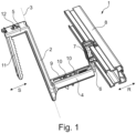
- FIG. 1 shows a perspective view of a tile hook 1 according to the invention.
- Tile hook 1 has a Z-shaped body constructed from an elongate base part 2 with a longitudinal axis 3, a first end part 4 and a second end part 5, these each extending at right angles, although in opposite directions, to the longitudinal axis 3.
- first mounting part 6 Placed into first end part 4 is a first mounting part 6 on which a clamp 7 with a frame tube 8 is arranged.
- the first mounting part 6 can be slid in direction R relative to first end part 4.
- the first mounting part 6 can be fixed in its position relative to first end part 4 by means of toothing 9 and 10 (see also figure 2 ).
- Resilient toothing 12 is provided to block second mounting part 11 in the desired position.
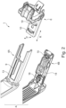
- Figure 2 shows tile hook 1 partially, with exploded parts.
- the first end part 4 is formed from a metal shell part 4A and a plastic shell part 4B.
- a slot 13 is provided in metal shell part 4A in the upper side, wherein a toothing 9 is arranged on the longitudinal edges.
- This toothing 9 co-acts with the two upright teeth 10, which are arranged on mounting part 6.
- the part with the upright teeth 10 is placed into first end part 4 in direction R and moved upward in direction T at the correct position in order to slide teeth 10 in toothing 9 and thereby lock the position.
- a partially wedge-shaped body 14 which is likewise slidable in direction R, is arranged on the plastic shell part 4B.
- resilient means 15, 16 which urge body 14 into the release position.
- Figure 3 shows a side view of shell part 4B and the partially wedge-shaped body 14 arranged thereon.
- Body 14 is provided on the underside with two rising surfaces 17, 18 which co-act with the respective rising surfaces 19, 20.
- the respective rising surfaces 17, 18, 19, 20 will lie against each other and will have moved the body 14 upward over a height h. This ensures that the upright teeth 10 are slid into the toothing 9 and held there.
- first locking protrusion 22 which co-acts with the second locking protrusion 23 at the end of rising surface 20.
- the partially wedge-shaped body 14 is hereby held in the locking position and cannot be slid back to the release position by resilient means 15, 16.
- the second locking protrusion 23 is arranged for resilient tilting, the engagement of the two locking protrusions 22, 23 can be broken by pressing against projection 24.
Landscapes
- Engineering & Computer Science (AREA)
- Architecture (AREA)
- Civil Engineering (AREA)
- Structural Engineering (AREA)
- Physics & Mathematics (AREA)
- Life Sciences & Earth Sciences (AREA)
- Sustainable Development (AREA)
- Sustainable Energy (AREA)
- Thermal Sciences (AREA)
- Chemical & Material Sciences (AREA)
- Combustion & Propulsion (AREA)
- Mechanical Engineering (AREA)
- General Engineering & Computer Science (AREA)
- Roof Covering Using Slabs Or Stiff Sheets (AREA)
- Connection Of Plates (AREA)
Claims (7)
- Ziegelhaken (1) zum Montieren eines Rahmens für beispielsweise Sonnenkollektoren auf einem Ziegeldach, wobei der Ziegelhaken (1) Folgendes umfasst:- einen Z-förmigen Körper, der ein längliches Basisteil, ein erstes Endteil (4), das sich von einem ersten Ende des länglichen Basisteils (2) im Wesentlichen senkrecht zu der Längsachse (3) des Basisteils erstreckt, und ein zweites Endteil (5), das sich von einem zweiten Ende (5) des länglichen Basisteils (2) im Wesentlichen senkrecht zu der Längsachse des Basisteils (2) und in entgegengesetzter Richtung zu der Richtung des ersten Endteils (4) erstreckt, aufweist;- ein erstes Montageteil (6) zum Montieren an einem Rahmen für beispielsweise Solarpanels, wobei das erste Montageteil (6) senkrecht zu der Längsachse des Basisteils (2) verschiebbar ist und an dem ersten Endteil (4) eingerichtet ist;wobei das erste Montageteil (6) eine erste Verzahnung (10) umfasst und wobei das erste Endteil eine zweite Verzahnung (9) umfasst;wobei das erste Montageteil (6) in einer Richtung parallel zu der Längsachse des Basisteils (2) zwischen einer ersten Position, in der die erste Verzahnung (10) und die zweite Verzahnung (9) ineinandergreifen, und einer zweiten Position, in der die erste Verzahnung (10) und die zweite Verzahnung (9) außer Eingriff miteinander sind, umziehbar ist,- Verriegelungsmittel zum Halten des ersten Montageteils in der ersten Position,dadurch gekennzeichnet, dass
die Verriegelungsmittel einen teilweiser keilförmigen Körper (14) umfassen, der senkrecht zu der Längsachse des Basisteils (2) zwischen einer Freigabeposition und einer Verriegelungsposition verschiebbar ist, wobei der teilweise keilförmige Körper (14) in der Verriegelungsposition das Montageteil (6) in der ersten Position hält und in der Freigabeposition das erste Montageteil (6) zwischen der ersten und zweiten Position frei verschiebbar ist. - Ziegelhaken (1) nach Anspruch 1, dadurch gekennzeichnet, dass eines des ersten Endes (4) und des ersten Montageteils (6) das andere teilweise umschließt, und wobei der teilweise keilförmige Körper (14) in der Verriegelungsposition zwischen dem umschließenden Teil und dem umschlossenen Teil positioniert ist.
- Ziegelhaken (1) nach Anspruch 2, dadurch gekennzeichnet, dass das Umschließungsteil aus mindestens zwei aufeinander eingerichteten Schalenteilen (4A, 4B) zusammengesetzt ist, die ein rohrförmiges Teil bilden, in das das umschlossene Teil hineinragt.
- Ziegelhaken (1) nach Anspruch 3, wobei das umschließende Teil das erste Ende (4) ist, und wobei eines der mindestens zwei Schalenteile (4A, 4B) ein Kunststoffschalenteil (4B) ist, das sich entlang des Z-förmigen Körpers bis zu dem zweiten Ende erstreckt.
- Ziegelhaken (1) nach einem der vorstehenden Ansprüche, der ferner elastische Mittel (15, 16) zum Drücken des teilweise keilförmigen Körpers (14) in die Freigabeposition umfasst;einen elastischen ersten Verriegelungsvorsprung (22), der quer zu der Verschieberichtung des teilweise keilförmigen Körpers (14) verschiebbar ist; undeinen zweiten Verriegelungsvorsprung (23), der an dem teilweise keilförmigen Körper (14) eingerichtet ist, wobei der erste Verriegelungsvorsprung (22) und der zweite Verriegelungsvorsprung (23) ineinander eingreifen können, um den teilweise keilförmigen Körper (14) in der Verriegelungsposition zu verriegeln.
- Ziegelhaken (1) nach einem der vorstehenden Ansprüche, der ferner ein zweites Montageteil (11) zum Montieren auf einem Dach umfasst, wobei das zweite Montageteil (11) L-förmig ist und senkrecht zu der Längsachse des Basisteils (2) verschiebbar und an dem zweiten Endteil mit einem Schenkel der L-Form eingerichtet ist, und wobei sich der andere Schenkel der L-Form parallel zu der Längsachse des Basisteils (2) erstreckt.
- Ziegelhaken (1) nach Anspruch 6, wobei sowohl das zweite Montageteil (11) als auch das zweite Endteil (5) mit einer ineinandergreifenden Verzahnung (12) versehen sind, um das zweite Montageteil (11) in einer Position relativ zu dem zweiten Endteil (5) zu verriegeln.
Applications Claiming Priority (1)
| Application Number | Priority Date | Filing Date | Title |
|---|---|---|---|
| NL2029180A NL2029180B1 (nl) | 2021-09-13 | 2021-09-13 | Dakpanhaak |
Publications (3)
| Publication Number | Publication Date |
|---|---|
| EP4148980A1 EP4148980A1 (de) | 2023-03-15 |
| EP4148980C0 EP4148980C0 (de) | 2025-02-12 |
| EP4148980B1 true EP4148980B1 (de) | 2025-02-12 |
Family
ID=78212592
Family Applications (1)
| Application Number | Title | Priority Date | Filing Date |
|---|---|---|---|
| EP22195172.6A Active EP4148980B1 (de) | 2021-09-13 | 2022-09-12 | Dachhaken |
Country Status (2)
| Country | Link |
|---|---|
| EP (1) | EP4148980B1 (de) |
| NL (1) | NL2029180B1 (de) |
Families Citing this family (2)
| Publication number | Priority date | Publication date | Assignee | Title |
|---|---|---|---|---|
| DE102023117924A1 (de) * | 2023-07-07 | 2025-01-09 | Fischer Italia S.R.L. | Befestiger zu einer Befestigung einer Montageschiene für Photovoltaikmodule auf einem Ziegeldach und Ziegeldach mit dem Befestiger |
| WO2025190475A1 (en) * | 2024-03-12 | 2025-09-18 | Allimex | Device for mounting solar panels on a roof |
Family Cites Families (6)
| Publication number | Priority date | Publication date | Assignee | Title |
|---|---|---|---|---|
| DE202009003745U1 (de) * | 2009-03-19 | 2009-07-16 | Haslinger, Rüdiger, Dipl.-Betriebsw. (FH) | Mehrteiliges Dachhakensystem |
| DE102010039838A1 (de) * | 2010-08-26 | 2012-03-01 | Bb-Stanz- Und Umformtechnik Gmbh | Profilschiene für Haltebügel |
| CN202834646U (zh) * | 2012-08-07 | 2013-03-27 | 苏州瑞得恩光能科技有限公司 | 铝合金挂钩 |
| NL2011649B3 (nl) * | 2013-10-18 | 2024-03-06 | Esdec B V | Inrichting en werkwijze voor het bevestigen van objecten, in het bijzonder zonnepanelen op een dak. |
| CN203562992U (zh) * | 2013-11-21 | 2014-04-23 | 清源科技(厦门)股份有限公司 | 一种用于安装太阳能板的支架系统 |
| BE1025426B1 (nl) * | 2017-11-29 | 2019-02-13 | Allimex | Inrichting voor het bevestigen van zonnepanelen |
-
2021
- 2021-09-13 NL NL2029180A patent/NL2029180B1/nl active
-
2022
- 2022-09-12 EP EP22195172.6A patent/EP4148980B1/de active Active
Also Published As
| Publication number | Publication date |
|---|---|
| NL2029180B1 (nl) | 2023-03-23 |
| EP4148980C0 (de) | 2025-02-12 |
| EP4148980A1 (de) | 2023-03-15 |
Similar Documents
| Publication | Publication Date | Title |
|---|---|---|
| EP4148980B1 (de) | Dachhaken | |
| KR100893636B1 (ko) | 조절 가능한 키보드 지지 조립체 | |
| US3836118A (en) | Adjustable work support assembly | |
| CZ2002887A3 (cs) | Střeąní a stropní systém pro budovy s plochou střechou | |
| EP3967455B1 (de) | Richtwerkzeug für befestigungsmittel | |
| KR20020047184A (ko) | 턴버클 장치 | |
| US11103109B2 (en) | Rail profile with attachment mechanism and related methods | |
| CA2006701C (en) | Snow guard | |
| US7610734B2 (en) | Siding installation apparatuses and methods for installing siding pieces on walls | |
| WO2007109839A1 (en) | A panel attachment clip | |
| CA3061999A1 (en) | Rail profile with attachment mechanism and related methods | |
| EP3842707B1 (de) | Montagevorrichtung zur montage von solarpaneelen an einer struktur | |
| AU2021295547A1 (en) | Fastening apparatus for fastening solar modules | |
| EP4102005B1 (de) | System zur befestigung plattenförmiger elemente für geländer, balustraden und brüstungen | |
| EP2871302B1 (de) | Montageanordnung für ein temporäres Kantenschutzsystem | |
| EP1297935A2 (de) | Fliesenschneider mit Längsanschlag und Winkelanschlag | |
| CA1307092C (en) | Bracket unit for fixing a roof gutter | |
| HUP9904496A2 (hu) | Rögzítőelem homlokzatlapokhoz | |
| EP4148338B1 (de) | Kombination aus klammer und profilträger | |
| EP0950864B1 (de) | Vorrichtung zum Montieren von Heizkörpern auf einem Untergrund | |
| JP2794564B2 (ja) | 屋根用スベリ止金具 | |
| US20160265239A1 (en) | Panel positioning device and associated methods | |
| JP3016334U (ja) | 樋支持金具 | |
| JPH08226227A (ja) | 足場板固定装置 | |
| JP3457621B2 (ja) | 雨樋支持具 |
Legal Events
| Date | Code | Title | Description |
|---|---|---|---|
| PUAI | Public reference made under article 153(3) epc to a published international application that has entered the european phase |
Free format text: ORIGINAL CODE: 0009012 |
|
| STAA | Information on the status of an ep patent application or granted ep patent |
Free format text: STATUS: THE APPLICATION HAS BEEN PUBLISHED |
|
| AK | Designated contracting states |
Kind code of ref document: A1 Designated state(s): AL AT BE BG CH CY CZ DE DK EE ES FI FR GB GR HR HU IE IS IT LI LT LU LV MC MK MT NL NO PL PT RO RS SE SI SK SM TR |
|
| RAP3 | Party data changed (applicant data changed or rights of an application transferred) |
Owner name: BLUBASE B.V. |
|
| STAA | Information on the status of an ep patent application or granted ep patent |
Free format text: STATUS: REQUEST FOR EXAMINATION WAS MADE |
|
| 17P | Request for examination filed |
Effective date: 20230718 |
|
| RBV | Designated contracting states (corrected) |
Designated state(s): AL AT BE BG CH CY CZ DE DK EE ES FI FR GB GR HR HU IE IS IT LI LT LU LV MC MK MT NL NO PL PT RO RS SE SI SK SM TR |
|
| STAA | Information on the status of an ep patent application or granted ep patent |
Free format text: STATUS: EXAMINATION IS IN PROGRESS |
|
| 17Q | First examination report despatched |
Effective date: 20231121 |
|
| GRAP | Despatch of communication of intention to grant a patent |
Free format text: ORIGINAL CODE: EPIDOSNIGR1 |
|
| STAA | Information on the status of an ep patent application or granted ep patent |
Free format text: STATUS: GRANT OF PATENT IS INTENDED |
|
| RIC1 | Information provided on ipc code assigned before grant |
Ipc: F24S 25/70 20180101ALI20240724BHEP Ipc: F24S 25/613 20180101ALI20240724BHEP Ipc: F24S 25/60 20180101ALI20240724BHEP Ipc: H02S 20/23 20140101AFI20240724BHEP |
|
| INTG | Intention to grant announced |
Effective date: 20240827 |
|
| GRAS | Grant fee paid |
Free format text: ORIGINAL CODE: EPIDOSNIGR3 |
|
| GRAA | (expected) grant |
Free format text: ORIGINAL CODE: 0009210 |
|
| STAA | Information on the status of an ep patent application or granted ep patent |
Free format text: STATUS: THE PATENT HAS BEEN GRANTED |
|
| AK | Designated contracting states |
Kind code of ref document: B1 Designated state(s): AL AT BE BG CH CY CZ DE DK EE ES FI FR GB GR HR HU IE IS IT LI LT LU LV MC MK MT NL NO PL PT RO RS SE SI SK SM TR |
|
| REG | Reference to a national code |
Ref country code: GB Ref legal event code: FG4D |
|
| REG | Reference to a national code |
Ref country code: CH Ref legal event code: EP |
|
| REG | Reference to a national code |
Ref country code: DE Ref legal event code: R096 Ref document number: 602022010429 Country of ref document: DE |
|
| REG | Reference to a national code |
Ref country code: IE Ref legal event code: FG4D |
|
| U01 | Request for unitary effect filed |
Effective date: 20250311 |
|
| U07 | Unitary effect registered |
Designated state(s): AT BE BG DE DK EE FI FR IT LT LU LV MT NL PT RO SE SI Effective date: 20250319 |
|
| RAP2 | Party data changed (patent owner data changed or rights of a patent transferred) |
Owner name: ENSTALL EUROPE B.V. |
|
| U1K | Transfer of rights of the unitary patent after the registration of the unitary effect |
Owner name: ENSTALL EUROPE B.V.; NL |
|
| PG25 | Lapsed in a contracting state [announced via postgrant information from national office to epo] |
Ref country code: RS Free format text: LAPSE BECAUSE OF FAILURE TO SUBMIT A TRANSLATION OF THE DESCRIPTION OR TO PAY THE FEE WITHIN THE PRESCRIBED TIME-LIMIT Effective date: 20250512 |
|
| PG25 | Lapsed in a contracting state [announced via postgrant information from national office to epo] |
Ref country code: PL Free format text: LAPSE BECAUSE OF FAILURE TO SUBMIT A TRANSLATION OF THE DESCRIPTION OR TO PAY THE FEE WITHIN THE PRESCRIBED TIME-LIMIT Effective date: 20250212 |
|
| PG25 | Lapsed in a contracting state [announced via postgrant information from national office to epo] |
Ref country code: ES Free format text: LAPSE BECAUSE OF FAILURE TO SUBMIT A TRANSLATION OF THE DESCRIPTION OR TO PAY THE FEE WITHIN THE PRESCRIBED TIME-LIMIT Effective date: 20250212 |
|
| PG25 | Lapsed in a contracting state [announced via postgrant information from national office to epo] |
Ref country code: IS Free format text: LAPSE BECAUSE OF FAILURE TO SUBMIT A TRANSLATION OF THE DESCRIPTION OR TO PAY THE FEE WITHIN THE PRESCRIBED TIME-LIMIT Effective date: 20250612 Ref country code: NO Free format text: LAPSE BECAUSE OF FAILURE TO SUBMIT A TRANSLATION OF THE DESCRIPTION OR TO PAY THE FEE WITHIN THE PRESCRIBED TIME-LIMIT Effective date: 20250512 |
|
| PG25 | Lapsed in a contracting state [announced via postgrant information from national office to epo] |
Ref country code: HR Free format text: LAPSE BECAUSE OF FAILURE TO SUBMIT A TRANSLATION OF THE DESCRIPTION OR TO PAY THE FEE WITHIN THE PRESCRIBED TIME-LIMIT Effective date: 20250212 |
|
| PG25 | Lapsed in a contracting state [announced via postgrant information from national office to epo] |
Ref country code: GR Free format text: LAPSE BECAUSE OF FAILURE TO SUBMIT A TRANSLATION OF THE DESCRIPTION OR TO PAY THE FEE WITHIN THE PRESCRIBED TIME-LIMIT Effective date: 20250513 |
|
| PG25 | Lapsed in a contracting state [announced via postgrant information from national office to epo] |
Ref country code: SM Free format text: LAPSE BECAUSE OF FAILURE TO SUBMIT A TRANSLATION OF THE DESCRIPTION OR TO PAY THE FEE WITHIN THE PRESCRIBED TIME-LIMIT Effective date: 20250212 |
|
| PG25 | Lapsed in a contracting state [announced via postgrant information from national office to epo] |
Ref country code: CZ Free format text: LAPSE BECAUSE OF FAILURE TO SUBMIT A TRANSLATION OF THE DESCRIPTION OR TO PAY THE FEE WITHIN THE PRESCRIBED TIME-LIMIT Effective date: 20250212 |
|
| PG25 | Lapsed in a contracting state [announced via postgrant information from national office to epo] |
Ref country code: SK Free format text: LAPSE BECAUSE OF FAILURE TO SUBMIT A TRANSLATION OF THE DESCRIPTION OR TO PAY THE FEE WITHIN THE PRESCRIBED TIME-LIMIT Effective date: 20250212 |
|
| U20 | Renewal fee for the european patent with unitary effect paid |
Year of fee payment: 4 Effective date: 20250929 |
|
| PLBE | No opposition filed within time limit |
Free format text: ORIGINAL CODE: 0009261 |
|
| STAA | Information on the status of an ep patent application or granted ep patent |
Free format text: STATUS: NO OPPOSITION FILED WITHIN TIME LIMIT |
|
| 26N | No opposition filed |
Effective date: 20251113 |