EP4148917B1 - Module d'alvéole de sécurité, et barrette d'alimentation et bobine de câble mobile comprenant un module d'alvéole de sécurité - Google Patents
Module d'alvéole de sécurité, et barrette d'alimentation et bobine de câble mobile comprenant un module d'alvéole de sécurité Download PDFInfo
- Publication number
- EP4148917B1 EP4148917B1 EP20939801.5A EP20939801A EP4148917B1 EP 4148917 B1 EP4148917 B1 EP 4148917B1 EP 20939801 A EP20939801 A EP 20939801A EP 4148917 B1 EP4148917 B1 EP 4148917B1
- Authority
- EP
- European Patent Office
- Prior art keywords
- waterproof
- contact piece
- switch
- electrical connection
- pin
- Prior art date
- Legal status (The legal status is an assumption and is not a legal conclusion. Google has not performed a legal analysis and makes no representation as to the accuracy of the status listed.)
- Active
Links
Images


Classifications
-
- H—ELECTRICITY
- H01—ELECTRIC ELEMENTS
- H01R—ELECTRICALLY-CONDUCTIVE CONNECTIONS; STRUCTURAL ASSOCIATIONS OF A PLURALITY OF MUTUALLY-INSULATED ELECTRICAL CONNECTING ELEMENTS; COUPLING DEVICES; CURRENT COLLECTORS
- H01R13/00—Details of coupling devices of the kinds covered by groups H01R12/70 or H01R24/00 - H01R33/00
- H01R13/66—Structural association with built-in electrical component
- H01R13/70—Structural association with built-in electrical component with built-in switch
- H01R13/713—Structural association with built-in electrical component with built-in switch the switch being a safety switch
-
- H—ELECTRICITY
- H01—ELECTRIC ELEMENTS
- H01R—ELECTRICALLY-CONDUCTIVE CONNECTIONS; STRUCTURAL ASSOCIATIONS OF A PLURALITY OF MUTUALLY-INSULATED ELECTRICAL CONNECTING ELEMENTS; COUPLING DEVICES; CURRENT COLLECTORS
- H01R13/00—Details of coupling devices of the kinds covered by groups H01R12/70 or H01R24/00 - H01R33/00
- H01R13/44—Means for preventing access to live contacts
- H01R13/447—Shutter or cover plate
-
- H—ELECTRICITY
- H01—ELECTRIC ELEMENTS
- H01R—ELECTRICALLY-CONDUCTIVE CONNECTIONS; STRUCTURAL ASSOCIATIONS OF A PLURALITY OF MUTUALLY-INSULATED ELECTRICAL CONNECTING ELEMENTS; COUPLING DEVICES; CURRENT COLLECTORS
- H01R13/00—Details of coupling devices of the kinds covered by groups H01R12/70 or H01R24/00 - H01R33/00
- H01R13/46—Bases; Cases
- H01R13/502—Bases; Cases composed of different pieces
-
- H—ELECTRICITY
- H01—ELECTRIC ELEMENTS
- H01R—ELECTRICALLY-CONDUCTIVE CONNECTIONS; STRUCTURAL ASSOCIATIONS OF A PLURALITY OF MUTUALLY-INSULATED ELECTRICAL CONNECTING ELEMENTS; COUPLING DEVICES; CURRENT COLLECTORS
- H01R13/00—Details of coupling devices of the kinds covered by groups H01R12/70 or H01R24/00 - H01R33/00
- H01R13/46—Bases; Cases
- H01R13/52—Dustproof, splashproof, drip-proof, waterproof, or flameproof cases
- H01R13/5202—Sealing means between parts of housing or between housing part and a wall, e.g. sealing rings
-
- H—ELECTRICITY
- H01—ELECTRIC ELEMENTS
- H01R—ELECTRICALLY-CONDUCTIVE CONNECTIONS; STRUCTURAL ASSOCIATIONS OF A PLURALITY OF MUTUALLY-INSULATED ELECTRICAL CONNECTING ELEMENTS; COUPLING DEVICES; CURRENT COLLECTORS
- H01R13/00—Details of coupling devices of the kinds covered by groups H01R12/70 or H01R24/00 - H01R33/00
- H01R13/62—Means for facilitating engagement or disengagement of coupling parts or for holding them in engagement
- H01R13/629—Additional means for facilitating engagement or disengagement of coupling parts, e.g. aligning or guiding means, levers, gas pressure electrical locking indicators, manufacturing tolerances
-
- H—ELECTRICITY
- H01—ELECTRIC ELEMENTS
- H01R—ELECTRICALLY-CONDUCTIVE CONNECTIONS; STRUCTURAL ASSOCIATIONS OF A PLURALITY OF MUTUALLY-INSULATED ELECTRICAL CONNECTING ELEMENTS; COUPLING DEVICES; CURRENT COLLECTORS
- H01R13/00—Details of coupling devices of the kinds covered by groups H01R12/70 or H01R24/00 - H01R33/00
- H01R13/66—Structural association with built-in electrical component
- H01R13/70—Structural association with built-in electrical component with built-in switch
- H01R13/703—Structural association with built-in electrical component with built-in switch operated by engagement or disengagement of coupling parts, e.g. dual-continuity coupling part
- H01R13/7031—Shorting, shunting or bussing of different terminals interrupted or effected on engagement of coupling part, e.g. for ESD protection, line continuity
-
- H—ELECTRICITY
- H01—ELECTRIC ELEMENTS
- H01R—ELECTRICALLY-CONDUCTIVE CONNECTIONS; STRUCTURAL ASSOCIATIONS OF A PLURALITY OF MUTUALLY-INSULATED ELECTRICAL CONNECTING ELEMENTS; COUPLING DEVICES; CURRENT COLLECTORS
- H01R13/00—Details of coupling devices of the kinds covered by groups H01R12/70 or H01R24/00 - H01R33/00
- H01R13/72—Means for accommodating flexible lead within the holder
-
- H—ELECTRICITY
- H01—ELECTRIC ELEMENTS
- H01R—ELECTRICALLY-CONDUCTIVE CONNECTIONS; STRUCTURAL ASSOCIATIONS OF A PLURALITY OF MUTUALLY-INSULATED ELECTRICAL CONNECTING ELEMENTS; COUPLING DEVICES; CURRENT COLLECTORS
- H01R13/00—Details of coupling devices of the kinds covered by groups H01R12/70 or H01R24/00 - H01R33/00
- H01R13/46—Bases; Cases
- H01R13/502—Bases; Cases composed of different pieces
- H01R13/506—Bases; Cases composed of different pieces assembled by snap action of the parts
-
- H—ELECTRICITY
- H01—ELECTRIC ELEMENTS
- H01R—ELECTRICALLY-CONDUCTIVE CONNECTIONS; STRUCTURAL ASSOCIATIONS OF A PLURALITY OF MUTUALLY-INSULATED ELECTRICAL CONNECTING ELEMENTS; COUPLING DEVICES; CURRENT COLLECTORS
- H01R24/00—Two-part coupling devices, or either of their cooperating parts, characterised by their overall structure
- H01R24/76—Two-part coupling devices, or either of their cooperating parts, characterised by their overall structure with sockets, clips or analogous contacts and secured to apparatus or structure, e.g. to a wall
Definitions
- the present disclosure relates to the field of electrical technologies, and specifically to a safety socket module and a power strip including the safety socket module.
- Some sockets and power strips in the prior art have certain moisture-proof, waterproof and electric-shock-proof functions. These functions are generally implemented by methods such as arranging a waterproof cover on sockets and power strips, arranging a leakage and short circuit protection device on sockets and power strips, arranging an anti-touch protection door on sockets and power strips, arranging a waterproof sealing gasket on sockets and power strips, etc.
- the above-mentioned solutions still have defects in reliability and safety.
- the rubber material used to seal the jack will wear out after repeated plugging and unplugging, resulting in an attenuation or loss of the sealing effect and consequently a current leakage risk.
- the waterproof cover can prevent splashing, the reliability is still not high, because the waterproof cover will be lifted and lose its protective effect after a plug of an electric appliance is inserted into a jack.
- the waterproof cover cannot prevent water intrusion, and it is not safe to use the waterproof cover outdoors, low-lying places, basements and other places prone to water accumulation.
- the sealing gasket has a certain protective effect when used in water with low pressure, but its protective effect tends to be ineffective in deep water or places with high pressure.
- CN 202 217 858 U relates to a waterproof anti-electric shock socket, comprising a housing, power supply output holes, drain holes, button holes, conductive copper sheets, insulating slide blocks, convex surface elastic seal warehouses, insulating buttons, seal rings, elastic covers and recessed surface elastic frames.
- US 2010/216326 A1 relates to an electrical safety receptacle with a cross-connection circuit.
- CN 202 363 643 U relates to an anti-electric shock safety socket.
- CN 208 656 040 U belongs to the technical field of the cable drum technique and specifically relates to a cable drum socket protective cover.
- US 10 243 296 B2 related to a safety socket which can prevent electric shock when inserted with foreign objects of a non-plug unit having a conductive property.
- a main objective of the present disclosure is to provide a safety socket module with a simple structure and high reliability, and a power strip including the safety socket module.
- the above safety socket module and power strip can provide effective waterproof and electric-shock-proof performances.
- a safety socket module including: a shell; an upper cover, configured to cover the shell and provided with a plurality of jacks; compartments, where a number of the compartments corresponds to a number of the jacks, each of the compartments is arranged in the shell and below a respective jack of the jacks, and an interior of each of the compartments is accessible from an exterior of the shell through the respective jack; waterproof electrical connection switches, arranged in the compartments and configured to asynchronously control connection and disconnection of a circuit between a power supply and a plug of an electric appliance; and lock control members, respectively arranged in the compartments and aligned with the jacks, and configured to clamp pins of the plug of the electric appliance and bias the waterproof electrical connection switches when the pins are inserted into the jacks, respectively, and disengage from the pins and reset the waterproof electrical connection switches when the pins are pulled out of the jacks, respectively.
- the biasing refers to lateral or outward pressing.
- the pin When the pin is inserted into the jack, the pin may cause the lock control member to move laterally and/or rotate outward to produce lateral or outward pressing.
- Each of the waterproof electrical connection switches includes an isolated waterproof chamber, and a movable contact piece and a static contact piece arranged opposite to each other in the isolated waterproof chamber.
- the isolated waterproof chamber is configured as a fully sealed structure, and a contact surface of the isolated waterproof chamber that is biased by a respective lock control member of the lock control members is elastically deformable.
- the safety socket module further includes a gasket, arranged between the compartments and the upper cover to seal the compartments and prevent a liquid from penetrating from one compartment to another compartment; a connection part of each of the waterproof electrical connection switches connected to a conductor in a bottom of the shell and an exposed part of the conductor are covered with a waterproof insulating material for a waterproof treatment; and a connection part of each of the lock control members connected to a conductor in the bottom of the shell and an exposed part of the conductor are covered with a waterproof insulating material for a waterproof treatment.
- the waterproof electrical connection switch is connected to another waterproof electrical connection switch or a lock control member through the conductor.
- the isolated waterproof chamber is a waterproof capsule
- the waterproof capsule includes a capsule base and a waterproof rubber sleeve fixed to the capsule base.
- the movable contact piece and the static contact piece are arranged inside the waterproof rubber sleeve, and the capsule base is formed by injection molding, and the movable contact piece and the static contact piece are fixed to the capsule base at the same time.
- An insulating elastic piece is arranged between the movable contact piece and the static contact piece to assist and correct a deformation and a rebound of the movable contact piece and the static contact piece.
- the movable contact piece and the static contact piece are respectively provided with contacts.
- the movable contact piece and the static contact piece are configured to contact with each other through the contacts.
- the capsule base is made of an insulating material by injection molding.
- the waterproof rubber sleeve is integrally made of an insulating, heat-resistant, and friction-resistant elastic material.
- a waterproof pad made of an insulating material is arranged on the upper cover.
- the waterproof pad is configured to cover a part of the upper cover and expose the jacks, and is configured to fit with the plug of the electric appliance to prevent water from entering the compartments through a gap between the plug of the electric appliance and the upper cover when the plug of the electric appliance is inserted into the jacks, and block a communication of water between the pins of the plug on a surface of the upper cover.
- a multi-rib waterproof structure made of an insulating material is arranged on the upper cover, and is configured to fit with a rubber pad mounted on the plug of the electric appliance to prevent water from entering the compartments through a gap between the plug of the electric appliance and the upper cover when the plug of the electric appliance is inserted into the jacks, and block a communication of water between the pins of the plug on a surface of the upper cover.
- At least two waterproof electrical connection switches controlled by the lock control members in different compartments are connected in series between a live wire of the power supply and the lock control member in the compartment of the safety socket module corresponding to the live wire.
- At least one waterproof electrical connection switch is connected in series between a neutral wire of the power supply and the lock control member in the compartment of the safety socket module corresponding to the neutral wire.
- At least two waterproof electrical connection switches controlled by the lock control members in different compartments are connected in series between a live wire of the power supply and the lock control member in the compartment of the safety socket module corresponding to the live wire; and at least two waterproof electrical connection switches controlled by the lock control members in different compartments are connected in series between a neutral wire of the power supply and the lock control member in the compartment of the safety socket module corresponding to the neutral wire.
- the upper cover is provided with a live wire jack corresponding to a live wire pin of the plug of the electric appliance and a neutral wire jack corresponding to a neutral wire pin of the plug of the electric appliance.
- the safety socket module includes a live wire compartment arranged below the live wire jack in the shell and a neutral wire compartment arranged below the neutral wire jack in the shell. Two waterproof electrical connection switches are arranged in each of the live wire compartment and the neutral wire compartment to form a protection circuit controlled by four switches.
- the upper cover is provided with a live wire jack corresponding to a live wire pin of the plug of the electric appliance, a neutral wire jack corresponding to a neutral wire pin of the plug of the electric appliance, and a ground wire jack corresponding to a ground wire pin of the plug of the electric appliance.
- the safety socket module includes a live wire compartment arranged below the live wire jack in the shell, a neutral wire compartment arranged below the neutral wire jack in the shell, and a ground wire compartment arranged below the ground wire jack in the shell.
- a total of four waterproof electrical connection switches are arranged in the live wire compartment, the neutral wire compartment, and the ground wire compartment to form a protection circuit controlled by four switches.
- the upper cover is provided with three live wire jacks corresponding to live wire pins of the plug of the electric appliance and a ground wire jack corresponding to a ground wire pin of the plug of the electric appliance.
- the safety socket module includes live wire compartments respectively arranged below the live wire jacks in the shell and a ground wire compartment arranged below the ground wire jack in the shell.
- At least two waterproof electrical connection switches controlled by the lock control members in different compartments are connected in series between each live wire of the power supply and the lock control member in each of the live wire compartments.
- a total of six waterproof electrical connection switches are arranged in the live wire compartments and the ground wire compartment to form a protection circuit controlled by six switches.
- each of the lock control members is made of a conductor material by integral molding and includes a push paddle arranged perpendicularly to a bottom surface of a respective one of the compartments and a fixing component, and the fixing component includes a pair of two clamping pieces; a plane where the push paddle lies is perpendicular to a plane where the fixing component lies; and the push paddle includes a bend near an end portion thereof, the bend includes a first bending portion abutting against a respective one of the waterproof electrical connection switches and a second bending portion facing toward a respective pin of the pins, and a spacing of the push paddle is set to match a width of the respective pin.
- the respective pin When the respective pin is inserted, the respective pin enters into contact with the second bending portion, and a distance by which the second bending portion moves laterally is transmitted to the movable contact piece in the respective one of the waterproof electrical connection switches through the first bending portion abutting against the respective one of the waterproof electrical connection switches. This distance is sufficient to provide a good contact between the movable contact piece and the static contact piece.
- the push paddle biases the movable contact piece to contact with the static contact piece only when a pin conforming to a size specified in a standard is inserted into a respective jack of the jacks, and does not bias the movable contact piece to contact with the static contact piece when a pin or other conductor not conforming to the size specified in the standard is inserted into the respective jack, so as to prevent an electric shock, and the push paddle resets when the respective pin is pulled out of the respective jack.
- the two clamping pieces are opposite to each other, each of the clamping pieces is provided near an end portion thereof with a bending portion facing toward the respective pin, and a distance between the two clamping pieces is set to match a thickness of the respective pin, so that the respective pin is tightly clamped by the bending portions of the clamping pieces to prevent a poor contact when being inserted into the respective jack, and the clamping pieces reset when the respective pin is pulled out of the respective jack.
- the bending angle and shape of the bending portion may be adjusted according to the required clamping degree. For example, a pointed bending portion provides a larger clamping force than a smooth bending portion. In practice, the clamping degree can be adjusted by selecting a suitable bending portion.
- the bending portion of each of the clamping pieces is closer to the respective jack than the bend of the push paddle is, to ensure that when the respective pin is inserted into the respective jack, the respective pin is first tightly clamped by the pair of clamping pieces and then pushes the push paddle, so as to prevent the generation of an electric arc when the respective pin is inserted.
- each of the lock control members is made of a conductor material and includes a split-molded push paddle arranged on a respective one of the compartments and a pair of clamping pieces arranged perpendicularly to a bottom surface of the respective one of the compartments.
- a cross-section of the push paddle is configured substantially in a V-shape with an opening facing downward, a top end of the push paddle is a hinge point, one side edge of the push paddle is close to a respective jack of the jacks, and the other side edge of the push paddle is covered with an insulating bush and abuts against a respective one of the waterproof electrical connection switches.
- An angle between the two side edges of the push paddle is set to match a width of a respective pin of the pins, so that the push paddle biases the movable contact piece to contact with the static contact piece only when a pin conforming to a size specified in a standard is inserted into the respective jack, and does not bias the movable contact piece to contact with the static contact piece when a pin or other conductor not conforming to the size specified in the standard is inserted into the respective jack, so as to prevent an electric shock, and that the push paddle resets when the respective pin is pulled out of the respective jack.
- the two clamping pieces are opposite to each other, each of the clamping pieces is provided near an end portion thereof with a bending portion facing toward the respective pin, and a distance between the two clamping pieces is configured to match a thickness of the respective pin, so that the respective pin is tightly clamped by the bending portions of the clamping pieces to prevent a poor contact when being inserted into the respective jack, and the clamping pieces reset when the respective pin is pulled out of the respective jack.
- the present disclosure also discloses a power strip, including: a power strip shell, an external power cable connected externally into the power strip shell, and an internal power cable arranged in the power strip shell.
- One or more safety socket modules are embedded in the power strip shell.
- the power strip shell is configured to expose the upper cover(s) of the one or more safety socket modules.
- the one or more safety socket modules are connected in parallel to the internal power cable.
- the external power cable is connected to the internal power cable through a mechanical switch.
- the mechanical switch includes: a switch button having a depressed position and a raised position, a push member connected to the switch button, and a switch waterproof capsule abutting against the push member.
- the switch waterproof capsule includes a switch movable contact piece and a switch static contact piece opposite to each other therein.
- the switch movable contact piece is connected to one of the external power cable and the internal power cable
- the switch static contact piece is connected to the other of the external power cable and the internal power cable.
- the mechanical switch includes two switch waterproof capsules.
- the switch movable contact piece and the switch static contact piece of one of the switch waterproof capsules are respectively connected to a live wire of the external power cable and a live wire of the internal power cable.
- the switch movable contact piece and the switch static contact piece of the other of the switch waterproof capsules are respectively connected to a neutral wire of the external power cable and a neutral wire of the internal power cable.
- Each of the switch waterproof capsules controls closing and opening of a circuit.
- the present disclosure also discloses a mobile cable reel, including: a drum; two baffles, respectively arranged on two opposing sides of the drum; a cable reel power cable, coiled on an outer periphery of the drum; one or more safety socket modules according to any one of the above embodiments, arranged on one or both of the two baffles; and one or more drain openings, arranged on one or both of the two baffles and corresponding to the one or more safety socket modules.
- the waterproof electrical connection switch is switched off, and water may enter the safety socket module and the power strip through the jacks, without causing any short circuit. After the plug is inserted into the jacks, the waterproof electrical connection switch is switched on.
- the safety socket module, the power strip and the mobile cable reel according to the present disclosure have a waterproof function and can be used in water immersion.
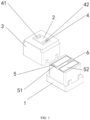
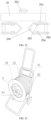
- FIG. 1 is a three-dimensional diagram of a safety socket module according to the present disclosure.
- the safety socket module includes: a shell 1; an upper cover 3, configured to cover the shell 1, where a plurality of jacks 4 are provided on the upper cover 3; compartments 5, where the number of the compartments 5 corresponds to the number of the jacks 4, each of the compartments 5 is arranged in the shell 1 and below a respective jack of the jacks 4, and an interior of each of the compartments 5 is accessible from an exterior of the shell 1 through the respective jack 4; and a gasket 6, arranged between the compartments 5 and the upper cover 3 to seal the compartments 5 and prevent a liquid from penetrating from one compartment 5 to another compartment 5.
- the upper cover 3 is provided with a live wire jack 41 corresponding to a live wire pin of a plug of an electric appliance and a neutral wire jack 42 corresponding to a neutral wire pin of the plug of the electric appliance.
- the safety socket module includes a live wire compartment 51 arranged below the live wire jack in the shell 1 and a neutral wire compartment 52 arranged below the neutral wire jack in the shell.
- a waterproof pad 2 made of an insulating material is arranged on the upper cover 3.
- the waterproof pad 2 is configured to cover a part of the upper cover 3 and expose the jacks 4, and is configured to fit with the plug of the electric appliance to prevent water from entering the compartments 5 through a gap between the plug of the electric appliance and the upper cover 3 when the plug of the electric appliance is inserted into the jacks 4, and block a communication of water between the pins of the plug on a surface of the upper cover.
- FIG. 2 is a three-dimensional diagram of a safety socket module according to another embodiment of the present disclosure.
- the embodiment in FIG. 2 differs from the embodiment in FIG. 1 in that: the upper cover 3 is provided with a multi-rib waterproof structure 27, and the plug of the electric appliance is equipped with a waterproof insulating rubber pad, which is used in combination with the multi-rib waterproof structure 27 to provide a stronger waterproof performance.
- Ribs and recesses formed by the multi-rib waterproof structure 27 are in contact with the waterproof insulating rubber pad under pressing, which can effectively prevent water from entering and moving between different ribs and recesses.
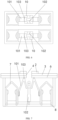
- FIG. 3 is a top view of the safety socket module in FIG. 1 , where the upper cover 3 is removed for convenience of description.
- the safety socket module includes: waterproof electrical connection switches 7, arranged in the compartments 5 and configured to asynchronously control connection and disconnection of a circuit between a power supply and a plug of an electric appliance; and lock control members 10, respectively arranged in the compartments and aligned with the jacks, and configured to clamp pins (not shown) of the plug of the electric appliance and bias the waterproof electrical connection switches 7 when the pins are inserted into the jacks 4, respectively, and disengage from the pins and reset the waterproof electrical connection switches 7 when the pins are pulled out of the jacks 4, respectively.
- the lock control members are configured to undergo a standard deformation of the lock control members when standard pins are inserted into the jacks, respectively, and produce a lateral or outward standard movement distance to bias the waterproof electrical connection switches, so as to switch on the waterproof electrical connection switches.
- the standard pin is a pin conforming to a size specified in a standard, which mainly means that the width of the pin conforms to the size specified in the standard, and further includes that the thickness of the pin conforms to the dimension specified in the standard.
- the compartments 5 include the live wire compartment 51 and the neutral wire compartment 52, and two waterproof electrical connection switches 7 are arranged in each of the live wire compartment 51 and the neutral wire compartment 52 to form a protection circuit controlled by four switches.
- a connection part of each of the waterproof electrical connection switches 7 connected to a conductor in a bottom of the shell and an exposed part of the conductor are covered with a waterproof insulating material for a waterproof treatment.
- the waterproof electrical connection switch 7 is connected to another part through a copper sheet, and an insulating material is poured to cover the connection part and the copper sheet.
- the waterproof electrical connection switch 7 is connected to another part through an insulated wire, and then the connection part is injection molded with an insulating material.
- a connection part of each of the lock control members 10 connected to a conductor in the bottom of the shell and an exposed part of the conductor are covered with a waterproof insulating material (for example, covered by pouring an insulating material or connected by an insulated wire) for a waterproof treatment.
- FIG. 4 is a side view of the safety socket module in FIG. 1 .
- the waterproof electrical connection switch 7 includes an isolated waterproof chamber, and a movable contact piece 13 and a static contact piece 14 arranged opposite to each other in the isolated waterproof chamber.
- the isolated waterproof chamber is configured as a fully sealed structure, and a contact surface of the isolated waterproof chamber that is biased by a respective lock control member of the lock control members is elastically deformable.
- the isolated waterproof chamber is a waterproof capsule 12.
- the movable contact piece 13 is configured to contact with the static contact piece 14 to switch on the waterproof electrical connection switch 7 through biasing of the lock control member 10 when the pin is inserted into the jack 4, and move away from the static contact piece to switch off the waterproof electrical connection switch 7 through resetting of the lock control member 10 when the pin is pulled out of the jack 4.
- a pin conforming to the size specified in the standard in the plug is inserted into the jack 4. Due to the insertion, the lock control member 10 is deformed and biases the elastically deformable surface of the isolated waterproof chamber, and the elastically deformable surface is deformed to bias the movable contact piece 13. Under the biasing, the movable contact piece moves and contacts with the static contact piece 14 to switch on the waterproof electrical connection switch 7.
- the movable contact piece 13 and the static contact piece 14 in the waterproof capsule 12 when not connected to the movable contact piece 13 and the static contact piece 14 in the waterproof capsule 12 in any other compartment 5, are not connected to the movable contact piece 13 and the static contact piece 14 in any other waterproof capsule 12 in the same compartment 5.
- the circuit needs to be closed by joint triggering of the lock control members 10 in different compartments.
- a conductive connector 8 in the waterproof capsule is configured to extend through the bottom of the compartment 5 and the waterproof capsule 12 to provide an electrical connection of the movable contact piece 13 and the static contact piece 14 to the lock control member 10 or other components.
- the conductive connector 8 in the waterproof capsule 12 may be an extension of the movable contact piece 13 or the static contact piece 14, i.e., the movable contact piece 13 or the static contact piece 14 is integrally formed with the corresponding conductive connector 8; or an independent conductive connector 8 may be connected to the movable contact piece 13 or the static contact piece 14.
- a conductive connector 8 in the lock control member 10 is configured to extend through the bottom of the compartment 5 to provide an electrical connection of the lock control member 10 to the movable contact piece 13 or the static contact piece 14 or other components.
- the conductive connector 8 in the lock control member 10 may be integrally formed with the lock control member 10; or an independent conductive connector 8 may be connected to the lock control member 10.
- the movable contact piece 13 and the static contact piece 14 are respectively provided with contacts 9.
- the movable contact piece 13 and the static contact piece 14 are configured to contact with each other through the contacts 9.
- the contacts 9 may be fixed on the movable contact piece 13 and the static contact piece 14 by welding.
- the lock control member 10 is made of a conductor material and includes a push paddle 101 arranged perpendicularly to a bottom surface of the compartment and a fixing component.
- the lock control member 10 is made of the conductor material by integral molding, and the fixing component includes a pair of clamping pieces 102.
- the conductor material may be phosphor bronze.
- a plane where the push paddle 101 lies is perpendicular to a plane where the fixing component lies.
- the push paddle 101 includes a bend near an end portion thereof, the bend includes a first bending portion 104 abutting against the waterproof electrical connection switch 7 and a second bending portion 105 facing toward the pin, and a spacing of the push paddle 101 is set to match a width of the pin (distance b in FIG.
- the push paddle 101 biases the movable contact piece 13 to contact with the static contact piece 14 only when a pin conforming to a size specified in a standard is inserted into the jack, and cannot bias the movable contact piece 13 to contact with the static contact piece 14 when a pin or other conductor not conforming to the size specified in the standard is inserted into the jack, so as to prevent an electric shock, and the push paddle 101 resets when the pin is pulled out of the jack 4.
- the two clamping pieces 102 are opposite to each other, each of the clamping pieces 102 is provided near an end portion thereof with a bending portion 106 facing toward the pin, and a distance between the two clamping pieces 102 is set to match a thickness of the pin (distance a in FIG. 24 ), so that the pin is tightly clamped by the bending portions 106 of the clamping pieces 102 when being inserted into the jack 4, so as to prevent poor contact, and the clamping pieces reset when the pin is pulled out of the jack 4.
- each of the clamping pieces 102 is closer to the jack 4 than the bend of the push paddle 101 is, to ensure that when the pin is inserted into the jack 4, the pin is first tightly clamped by the pair of clamping pieces 102 and then pushes the push paddle, so as to prevent the generation of an electric arc.
- FIG. 5 is a cross-sectional view of a waterproof electrical connection switch of a safety socket module according to another embodiment of the present disclosure.
- the waterproof capsule 12 includes a capsule base 15 and a waterproof rubber sleeve 16 fixed to the capsule base 15.
- the waterproof rubber sleeve 16 may be bonded to the capsule base 15 by a waterproof adhesive.
- the movable contact piece 13 and the static contact piece 14 are arranged inside the waterproof rubber sleeve 16 and fixed to the capsule base 15 by injection molding.
- the capsule base 15 is made of an insulating material by injection molding.
- the waterproof rubber sleeve 16 is integrally made of an insulating, heat-resistant, and friction-resistant elastic material, for example, by integral molding, high-frequency welding or other processes.
- the above elastic material may be silica gel.
- the embodiment in FIG. 5 differs from the embodiment in FIG. 4 in that: an insulating elastic piece 17 is arranged between the movable contact piece 13 and the static contact piece 14 to assist and correct the deformation and rebound of the movable contact piece 13 and the static contact piece 14.
- FIG. 6 is a top view of a safety socket module according to another embodiment of the present disclosure.
- the lock control member 10 is made of a conductor material and includes a push paddle 101 hinged on the compartment 5 and a pair of clamping pieces 102 arranged perpendicularly to a bottom surface of the compartment.
- the conductor material may be phosphor bronze.
- each of the clamping pieces 102 is provided near an end portion thereof with a bending portion 106 facing toward the pin, and a distance between the two clamping pieces 102 is set to match a thickness of the pin (distance a in FIG. 24 ), so that the pin is tightly clamped by the bending portions 106 of the clamping pieces 102 when being inserted into the jack 4, so as to prevent poor contact, and the clamping pieces reset when the pin is pulled out from the jack 4.
- FIG. 7 is a side view of the safety socket module in FIG. 6 .
- a cross-section of the push paddle 101 is configured substantially in a V-shape with an opening facing downward, a top end of the push paddle is a hinge point 103, one side edge of the push paddle is close to the jack 4, and the other side edge of the push paddle is covered with an insulating bush and abuts against the waterproof electrical connection switch 7.
- An angle between the two side edges of the push paddle 101 is set to match a width of the pin (distance b in FIG.
- the push paddle 101 biases the movable contact piece 13 to contact with the static contact piece 14 only when a pin conforming to a size specified in a standard is inserted into the jack 4, and cannot bias the movable contact piece 13 to contact with the static contact piece 14 when a pin or other conductor not conforming to the size specified in the standard is inserted into the jack 4, and that the push paddle resets through the rebound of the waterproof electrical connection switch 7 when the pin is pulled out from the jack 4.
- the lengths of and the angle between the two side edges of the pushing paddle 101 and the shape of the bending portion of the clamping piece 102 are designed to ensure that when the pin is inserted into the jack 4, the pin is first tightly clamped by the pair of clamping pieces 102 and then pushes the push paddle 101, so as to prevent the generation of an electric arc.
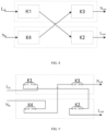
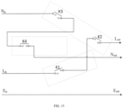
- FIG. 8 is an electrical schematic diagram of the safety socket module in FIG. 1 .
- a live wire (L in ) from a power supply is connected to a live wire (L out ) of a pin after being controlled in series by two waterproof electrical connection switches 7 (K1 and K2 in the figure).
- a neutral wire (N in ) from the power supply is connected to a neutral wire (N out ) of the pin after being controlled in series by two waterproof electrical connection switches 7 (K3 and K4 in the figure).
- FIG. 9 is a circuit diagram of the safety socket module in FIG. 1 .
- a movable contact piece 13 (b 1 in the figure) of a first waterproof electrical connection switch K1 in a live wire compartment 51 is connected to a live wire (L in in the figure) of a power supply.
- a static contact piece 14 (a1 in the figure) of the first waterproof electrical connection switch K1 is connected to a static contact piece 14 (a2 in the figure) of a second waterproof electrical connection switch K2 in a neutral wire compartment 52.
- a movable contact piece 13 (b2 in the figure) of the second waterproof electrical connection switch K2 is connected to a lock control member 10 in the live wire compartment 51 and then connected to a live wire (L out in the figure) of a pin (or may be connected to a lock control member 10 in the neutral wire compartment 52, where the lock control member 10 in the corresponding neutral wire compartment 52 is at the same potential as the live wire).
- a movable contact piece 13 (b4 in the figure) of a fourth waterproof electrical connection switch K4 in the neutral wire compartment 52 is connected to a neutral wire (N in in the figure) of the power supply.
- a static contact piece 14 (a4 in the figure) of the fourth waterproof electrical connection switch K4 is connected to a movable contact piece 13 (b3 in the figure) of a third waterproof electrical connection switch K3 in the live wire compartment 51.
- a static contact piece 14 (a3 in the figure) of the third waterproof electrical connection switch K3 is connected to the lock control member 10 in the neutral wire compartment 52 and then connected to a neutral wire (N out in the figure) of the pin (or may be connected to the lock control member 10 in the live wire compartment 51, where the lock control member 10 in the corresponding live wire compartment 51 is at the same potential as the neutral wire).
- the connecting wires of the movable contact piece and the static contact piece in the same waterproof electrical connection switch may be interchangeable (for example, a1 and b1 are interchangeable), and the selection of the waterproof electrical connection switch may also be changed, as long as one circuit includes the waterproof electrical connection switches controlled by the lock control members in two different compartments, for example, K1 and K4 are connected to each other and K3 and K2 are connected to each other. In this way, it is ensured that only when pins satisfying the standard are inserted into two jacks at the same time, the live wire circuit can be connected to the neutral wire circuit.
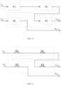
- FIG. 10 is an electrical schematic diagram of a safety socket module according to another embodiment of the present disclosure.
- the embodiment in FIG. 10 differs from the embodiment in FIG. 8 in that: a live wire (L in ) from a power supply is connected to a live wire (L out ) of a pin after being controlled in series by three waterproof electrical connection switches 7 (K1, K2, and K3 in the figure).
- a neutral wire (N in ) from the power supply is connected to a neutral wire (N out ) of a pin after being controlled by one waterproof electrical connection switch 7 (K4 in the figure).
- K4 waterproof electrical connection switch 7
- FIG. 11 is a circuit diagram of the safety socket module in FIG. 10 .
- a static contact piece 14 (a1 in the figure) of a first waterproof electrical connection switch K1 in a live wire compartment 51 is connected to a live wire (L in in the figure) of a power supply.
- a movable contact piece 13 (b1 in the figure) of the first waterproof electrical connection switch K1 is connected to a static contact piece 14 (a2 in the figure) of a second waterproof electrical connection switch K2 in the live wire compartment 51.
- a movable contact piece 13 (b2 in the figure) of the second waterproof electrical connection switch K2 is connected to a static contact piece 14 (a3 in the figure) of a third waterproof electrical connection switch K3 in a neutral wire compartment 52.
- a movable contact piece 13 (b3 in the figure) of the third waterproof electrical connection switch K3 is connected to a lock control member 10 in the live wire compartment 51 and then connected to a live wire (L out in the figure) of the pin.
- a static contact piece 14 (a4 in the figure) of a fourth waterproof electrical connection switch K4 in the neutral wire compartment 52 is connected to a neutral wire (N in in the figure) of the power supply.
- a movable contact piece 13 (b4 in the figure) of the fourth waterproof electrical connection switch K4 is connected to a lock control member 10 in the neutral wire compartment 52 and then connected to a neutral wire (N out in the figure) of the pin. It should be noted that other connection sequences also fall within the protection scope of the present disclosure.
- the closing or opening of the circuit is controlled through a plurality of waterproof electrical connection switches, different numbers of waterproof electrical connection switches are selected depending on different situations, and particularly, the closing of the live wire circuit is controlled preferentially by using at least two waterproof electrical connection switches controlled by lock control members in different compartments, so as to ensure that the live wire circuit can be closed only when pins satisfying the standard are inserted into two jacks at the same time.
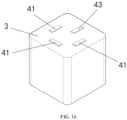
- FIG. 12 is a three-dimensional diagram of a safety socket module according to another embodiment of the present disclosure.
- the embodiment in FIG. 12 differs from the embodiment in FIG. 1 in that: the upper cover 3 is provided with a live wire jack 41 corresponding to a live wire pin of the plug of the electric appliance, a neutral wire jack 42 corresponding to a neutral wire pin of the plug of the electric appliance, and a ground wire jack 43 corresponding to a ground wire pin of the plug of the electric appliance.
- the safety socket module includes a live wire compartment 51 arranged below the live wire jack in the shell 1, a neutral wire compartment 52 arranged below the neutral wire jack in the shell 1, and a ground wire compartment 53 arranged below the ground wire jack in the shell 1.
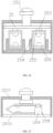
- FIG. 13 is a top view of the safety socket module in FIG. 12 .
- a total of four waterproof electrical connection switches 7 are arranged in the live wire compartment 51, the neutral wire compartment 52, and the ground wire compartment 53 to form a protection circuit controlled by four switches.
- two of the four waterproof electrical connection switches 7 may be arranged in the live wire compartment 51, and one arranged in each of the neutral wire compartment 52 and the ground wire compartment 53; or two may be arranged in the neutral wire compartment 52, and one arranged in each of the live wire compartment 51 and the ground wire compartment 53; or two may be arranged in the ground wire compartment 53, and one arranged in each of the live wire compartment 51 and the neutral wire compartment 52.
- FIG. 14 is an electrical schematic diagram of the safety socket module in FIG. 12 .
- a live wire (L in ) from a power supply is connected to a lock control member 10 (L out ) in a live wire compartment 51 after being controlled in series by two waterproof electrical connection switches 7 (K1 and K2 in the figure).
- a neutral wire (N in ) from the power supply is connected to a lock control member 10 (N out ) in a neutral wire compartment 52 after being controlled by two waterproof electrical connection switches 7 (K3 and K4 in the figure).
- a ground wire (E in ) from the power supply is directly connected to a lock control member 10 (E out ) in a ground wire compartment 53.
- the waterproof electrical connection switch 7 may not participate in the control of the circuit of the corresponding compartment.
- the waterproof electrical connection switch 7 in the ground wire compartment 53 only occupies space in the ground wire compartment 53, and actually participates in the control of the neutral wire circuit.
- FIG. 15 is a circuit diagram of the safety socket module in FIG. 12 .
- a static contact piece 14 (a1 in the figure) of a first waterproof electrical connection switch K1 in a neutral wire compartment 52 is connected to a live wire (L in in the figure) of a power supply.
- a movable contact piece 13 (b1 in the figure) of the first waterproof electrical connection switch K1 is connected to a static contact piece 14 (a2 in the figure) of a second waterproof electrical connection switch K2 in a live wire compartment 51.
- a movable contact piece 13 (b2 in the figure) of the second waterproof electrical connection switch K2 is connected to a lock control member 10 in a live wire compartment 51 and then connected to a live wire (L out in the figure) of a pin.
- a static contact piece 14 (a3 in the figure) of a third waterproof electrical connection switch K3 in the live wire compartment 51 is connected to a neutral wire (N in in the figure) of the power supply;
- a movable contact piece 13 (b3 in the figure) of the third waterproof electrical connection switch K3 is connected to a static contact piece 14 (a4 in the figure) of a fourth waterproof electrical connection switch K4 in a ground wire compartment 53.
- a movable contact piece 13 (b4 in the figure) of the fourth waterproof electrical connection switch K4 is connected to a lock control member 10 in a neutral wire compartment 52 and then connected to a neutral wire (N out in the figure) of the pin.
- a ground wire (E in in the figure) of the power supply is directly connected to a ground wire (E out in the figure) of the pin through a lock control member 10 in the ground wire compartment 53. It should be noted that other connection sequences also fall within the protection scope of the present disclosure.
- FIG. 16 is a three-dimensional diagram of a safety socket module according to a fourth embodiment of the present disclosure.
- the embodiment in FIG. 16 differs from the embodiment in FIG. 1 in that: the upper cover 3 is provided with three live wire jacks 41 corresponding to live wire pins of the plug of the electric appliance and a ground wire jack 43 corresponding to a ground wire pin of the plug of the electric appliance.
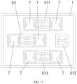
- FIG. 17 is a top view of the safety socket module in FIG. 16 .
- the safety socket module includes: a first live wire compartment 511, a second live wire compartment 512 and a third live wire compartment 513 which are respectively arranged below the three live wire jacks in the shell 1; and a ground wire compartment 53 arranged below the ground wire jack in the shell 1.
- Two waterproof electrical connection switches 7 are arranged in each of the first live wire compartment 511, the ground wire compartment 53, and the third live wire compartment 513 to form a protection circuit controlled by six switches.
- FIG. 18 is an electrical schematic diagram of the safety socket module in FIG. 16 .
- a first live wire (L1 in ) from a power supply is connected to a first live wire (L1 out ) of a pin after being controlled in series by two waterproof electrical connection switches 7 (K1 and K2 in the figure).
- a second live wire (L2 in ) from the power supply is connected to a second live wire (L2 out ) of the pin after being controlled in series by two waterproof electrical connection switches 7 (K3 and K4 in the figure).
- a third live wire (L3 in ) from the power supply is connected to a third live wire (L3 out ) of the pin after being controlled in series by two waterproof electrical connection switches 7 (K5 and K6 in the figure).
- a ground wire (E in ) from the power supply is directly connected to a ground wire (E out ) of the pin.
- FIG. 19 is a circuit diagram of the safety socket module in FIG. 16 .
- a static contact piece 14 (a1 in the figure) of a first waterproof electrical connection switch K1 in a first live wire compartment 511 is connected to a first live wire (L1 in in the figure) of a power supply.
- a movable contact piece 13 (b1 in the figure) of the first waterproof electrical connection switch K1 is connected to a static contact piece 14 (a2 in the figure) of a second waterproof electrical connection switch K2 in a third live wire compartment 513.
- a movable contact piece 13 (b2 in the figure) of the second waterproof electrical connection switch K2 is connected to a lock control member 10 in the first live wire compartment 511 and then connected to a first live wire (L1 out in the figure) of a pin.
- a static contact piece 14 (a3 in the figure) of a third waterproof electrical connection switch K3 in the first live wire compartment 511 is connected to a second live wire (L2 in in the figure) of the power supply.
- a movable contact piece 13 (b3 in the figure) of the third waterproof electrical connection switch K3 is connected to a static contact piece 14 (a4 in the figure) of a fourth waterproof electrical connection switch K4 in the second live wire compartment 512.
- a movable contact piece 13 (b4 in the figure) of the fourth waterproof electrical connection switch K4 is connected to a lock control member 10 in the second live wire compartment 512 and then connected to a second live wire (L2 out in the figure) of the pin.
- a static contact piece 14 (a5 in the figure) of a fifth waterproof electrical connection switch K5 in the second live wire compartment 512 is connected to a third live wire (L3 in in the figure) of the power supply.
- a movable contact piece 13 (b5 in the figure) of the fifth waterproof electrical connection switch K5 is connected to a static contact piece 14 (a6 in the figure) of a sixth waterproof electrical connection switch K6 in the third live wire compartment 513.
- a movable contact piece 13 (b6 in the figure) of the sixth waterproof electrical connection switch K6 is connected to a lock control member 10 in the third live wire compartment 513 and then connected to a third live wire (L3 out in the figure) of the pin.
- a ground wire (E in in the figure) of the power supply is directly connected to a ground wire (E out in the figure) of the pin through a lock control member 10 in a ground wire compartment 53. It should be noted that other connection sequences also fall within the protection scope of the present disclosure.
- FIG. 20 is a top view of a safety socket module according to another embodiment of the present disclosure.
- the embodiment in FIG. 20 differs from the embodiment in FIG. 16 in that: one waterproof electrical connection switch 7 is arranged in each of the first live wire compartment 511 and the third live wire compartment 513, and two waterproof electrical connection switches 7 are arranged in each of the second live wire compartment 512 and the ground wire compartment 53, to form a protection circuit controlled by six switches.
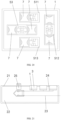
- FIG. 21 is a cross-sectional view of a power strip according to the present disclosure.
- the power strip includes: a power strip shell 21; an external power cable 23, connected externally into the power strip shell; and an internal power cable 24, arranged in the power strip shell.
- One or more safety socket modules are embedded in the power strip shell 21.
- the one or more safety socket modules in the power strip may have the same or different numbers of jacks. It should be noted that, for safety reasons, an industrial 4-pin safety socket module is not allowed to be arranged in the same power strip as 2-pin and 3-pin safety socket modules.
- the power strip shell 21 is configured to expose the upper cover 3 of the safety socket module.
- the safety socket modules are connected in parallel to the internal power cable 24.
- the external power cable 23 is connected to the internal power cable 24 through a mechanical switch 25.
- FIG. 22 is a cross-sectional view of a mechanical switch of the power strip in FIG. 21 .
- the mechanical switch 25 includes: a switch button 252 having a depressed position and a raised position; a push member 253, connected to the switch button 252; and a switch waterproof capsule 254, abutting against the push member 253.
- the switch waterproof capsule 254 includes a switch movable contact piece 255 and a switch static contact piece 256 opposite to each other therein.
- the switch movable contact piece 255 is connected to one of the external power cable 23 and the internal power cable 24, and the switch static contact piece 256 is connected to the other of the external power cable 23 and the internal power cable 24.
- the switch movable contact piece 255 is configured to contact with the switch static contact piece 256 to connect the external power cable 23 to the internal power cable 24 through biasing of the push member 253 when the switch button 252 is in the depressed position, and to move away from the switch static contact piece 256 to disconnect the external power cable 23 from the internal power cable 24 through retraction of the push member 253 when the switch button 252 is in the raised position. Since most of neutral wires of power grids carry electricity in real life, two mechanical switches are required to control the connection and disconnection of the live wire and the neutral wire respectively during plugging and unplugging in water. In this embodiment, the mechanical switch 25 includes two switch waterproof capsules 254.
- the switch movable contact piece 255 and the switch static contact piece 256 of one of the switch waterproof capsules 254 are respectively connected to a live wire of the external power cable 23 and a live wire of the internal power cable 24.
- the switch movable contact piece 255 and the switch static contact piece 256 of the other of the switch waterproof capsules 254 are respectively connected to a neutral wire of the external power cable 23 and a neutral wire of the internal power cable 24.
- a switch conductive connector 258 is configured to extend through the switch waterproof capsule 254 to provide an electrical connection of the switch movable contact piece 255 and the switch static contact piece 256 to other components.
- the mechanical switch further includes a mechanical switch upper cover 2511, a mechanical switch bottom cover 2510, and a switch waterproof capsule fixing plate 259, as shown in FIG. 26 and FIG. 27 .
- the switch conductive connector 258 is a conductor covered with an insulating layer (insulated wire), and is connected to the contact pieces in the switch waterproof capsule 254, and is injection molded with an insulating material on the bottom of the switch waterproof capsule, to provide a waterproof function for the electrical connection part.
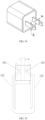
- FIG. 23 is a three-dimensional diagram of a mobile cable reel according to the present disclosure.
- the mobile cable reel includes: a drum 31; two baffles 32, respectively arranged on two opposing sides of the drum 31; a cable reel power cable 33, coiled on an outer periphery of the drum 31; a plurality of safety socket modules (the upper covers 3 of which are exposed in the figure) arranged on the baffles 32; and drain openings 34, arranged on the baffles (32) and corresponding to the safety socket modules.
- this embodiment separately provides a waterproof electrical connection switch, including: an isolated waterproof chamber, and a movable contact piece 13 and a static contact piece 14 arranged opposite to each other in the isolated waterproof chamber.
- the isolated waterproof chamber is configured as a fully sealed structure, and has at least one flexible surface which is elastically deformable.
- the movable contact piece 13 is configured to deform and contact with the static contact piece 14 when an external force is applied to the flexible surface, so as to switch on the waterproof electrical connection switch. When the external force is released, the movable contact piece 13 resets and moves away from the static contact piece 14, so as to switch off the waterproof electrical connection switch.
- the waterproof electrical connection switch as a whole is installed in the compartment 5 of the socket as an independent electrical connection switch.
- the flexible surface is configured in such a manner that when a pin with a standard width or with a standard width and thickness is inserted into the jack, the pin acts on the lock control member 10 and biases the flexible surface to produce a standard deformation.
- the movable contact piece 13 is configured to move laterally or outward by a standard deformation distance to bias the static contact piece 14 when the flexible surface is deformed; and move away from the static contact piece 14 to switch off the waterproof electrical connection switch when the flexible surface recovers from the standard deformation.
- the lock control member 10 is configured to undergo a standard deformation when a standard pin is inserted into the jack, and produce a lateral or outward standard movement distance to bias the waterproof electrical connection switch, so as to switch on the switch.
- the isolated waterproof chamber is a waterproof capsule 12, which includes a capsule base 15 and a waterproof rubber sleeve 16 fixed to the capsule base 15.
- the movable contact piece 13 and the static contact piece 14 are arranged inside the waterproof rubber sleeve and fixed to the capsule base 15.
- the movable contact piece 13 and the static contact piece 14 are respectively provided with contacts 9.
- the movable contact piece 13 and the static contact piece 14 are configured to contact with each other through the contacts 9.
- an insulating elastic piece 17 is arranged between the movable contact piece 13 and the static contact piece 14 to assist and correct the deformation and rebound of the movable contact piece 13 and the static contact piece 14.
- the waterproof electrical connection switch includes conductive connectors 8.
- the movable contact piece 13 or the static contact piece 14 in the isolated waterproof chamber is integrally formed with the corresponding conductive connector 8; or the movable contact piece 13 or the static contact piece 14 in the isolated waterproof chamber is electrically connected to the corresponding independent conductive connector 8.
- the conductive connector 8 is an insulated wire
- the movable contact piece 13 or the static contact piece 14 in the isolated waterproof chamber is connected to one end of the corresponding insulated wire
- the connection part is subjected to injection molding process to form a capsule base 15, and another end of the insulated wire runs through the capsule base 15.
- the conductive connector 8 of the waterproof electrical connection switch is configured to electrically connect to a lock control member 10, which is used for receiving insertion of a pin, in the same compartment 5, so that when the waterproof electrical connection switch is switched on, the circuit of the compartment 5 is closed; and/or the conductive connecting piece 8 of the waterproof electrical connection switch is configured to electrically connect to a lock control member 10, which is used for receiving insertion of a pin, in another compartment 5, so that when the waterproof electrical connection switch is switched on, the circuit of the another compartment 5 is closed.
- a connection part of the waterproof electrical connection switch connected to a conductor in the bottom of the compartment 5 and an exposed part of the conductor are covered with a waterproof insulating material for waterproof treatment.
- a waterproof mechanical switch including: a switch button (252) having a depressed position and a raised position, a push member (253), connected to the switch button, and a switch waterproof capsule (254), abutting against the push member, the switch waterproof capsule includes a switch movable contact piece (255) and a switch static contact piece (256) opposite to each other therein; the switch movable contact piece is connected to one of the external power cable and the internal power cable, and the switch static contact piece is connected to the other of the external power cable and the internal power cable; and the switch movable contact piece is configured to contact with the switch static contact piece to connect the external power cable to the internal power cable through biasing of the push member when the switch button is in the depressed position, and to move away from the switch static contact piece to disconnect the external power cable from the internal power cable through a retraction of the push member when the switch
- the mechanical switch includes two switch waterproof capsules; the switch movable contact piece and the switch static contact piece of one of the switch waterproof capsules are respectively connected to a live wire of the external power cable and a live wire of the internal power cable; the switch movable contact piece and the switch static contact piece of the other of the switch waterproof capsules are respectively connected to a neutral wire of the external power cable and a neutral wire of the internal power cable; and each of the switch waterproof capsules controls closing and opening of a circuit.
- the waterproof electrical connection switches in this embodiment may be supplemented by corresponding structures in other embodiments, and the structures such as the lock control members in this embodiment may be supplemented or replaced by corresponding structures in other embodiments.
- the solution of this embodiment Compared with solutions where the lock control member is not used and an conductor is inserted to directly act on the electrical connection switch, the solution of this embodiment has higher requirements for the standardization of the conductor, and there is an extremely low possibility that the waterproof electrical connection switch will be switched on by a pin which is not from a plug. Therefore, the solution of connecting a pin to a power supply through a lock control member that causes a standard movement can achieve the better electric-shock-proof performance.
- the lock control member is made of a conductor material and includes a push paddle 101 arranged perpendicularly to a bottom surface of the compartment 5 and a fixing component, and the fixing component includes a pair of clamping pieces 102; a plane where the push paddle 101 lies is perpendicular to a plane where the fixing component lies; and the push paddle 101 includes a bend near an end portion thereof, the bend includes a first bending portion 104 abutting against the waterproof electrical connection switch and a second bending portion 105 facing toward the pin, and a spacing of the push paddle 101 is set to match a width of the pin, so that the push paddle 101 biases the movable contact piece 13 to contact with the static contact piece 14 only when a pin conforming to a size specified in a standard is inserted into the jack, and cannot bias the movable contact piece to contact with the static contact piece 14 when a pin or other conductor not conforming to the size specified in the standard is inserted into the jack, and
- the two clamping pieces 102 are opposite to each other, each of the clamping pieces 102 is provided near an end portion thereof with a bending portion 106 facing toward the pin, and a distance between the two clamping pieces 102 is set to match a thickness of the pin, so that the pin is tightly clamped by the bending portions 106 of the clamping pieces 102 when being inserted into the jack, and the clamping pieces reset when the pin is pulled out from the jack.
- the bending portion of each of the clamping pieces 102 is closer to the jack than the bend of the push paddle 101 is, to ensure that when the pin is inserted into the jack, the pin is first tightly clamped by the pair of clamping pieces 102 and then pushes the push paddle 101.
- the lock control member is made of a conductor material and includes a split-molded push paddle 101 arranged on the compartment 5 and a pair of clamping pieces 102 arranged perpendicularly to a bottom surface of the compartment 5.
- a cross-section of the push paddle 101 is configured substantially in a V-shape with an opening facing downward, a top end of the push paddle is a hinge point 103, one side edge of the push paddle is close to the jack, and the other side edge of the push paddle is covered with an insulating bush and abuts against the waterproof electrical connection switch.
- An angle between the two side edges of the push paddle 101 is set to match a width of the pin, so that the push paddle 101 biases the movable contact piece 13 to contact with the static contact piece 14 only when a pin conforming to a size specified in a standard is inserted into the jack, and cannot bias the movable contact piece 13 to contact with the static contact piece 14 when a pin or other conductor not conforming to the size specified in the standard is inserted into the jack, and that the push paddle resets when the pin is pulled out from the jack.
- the lock control members are respectively arranged in the compartments 5 and aligned with the jacks, the number of the compartments 5 corresponds to the number of the jacks, each of the compartments 5 is arranged in the shell and below a respective jack of the jacks, and an interior of each of the compartments 5 is accessible from an exterior of the shell through the respective jack.
- lock control members in this embodiment may be supplemented by corresponding structures in other embodiments, and the structures such as the waterproof electrical connection switches in this embodiment may be supplemented or replaced by corresponding structures in other embodiments.
- a first 3-pin safety socket including: a shell 1; an upper cover 3, configured to cover the shell and provided with three jacks 4, where the upper cover is provided with a live wire jack corresponding to a live wire pin of a plug of an electric appliance, a neutral wire jack corresponding to a neutral wire pin of the plug of the electric appliance, and a ground wire jack corresponding to a ground wire pin of the plug of the electric appliance; compartments 5, where the number of the compartments corresponds to the number of the jacks, each of the compartments 5 is arranged in the shell 1 and below a respective jack of the jacks, an interior of each of the compartments 5 is accessible from an exterior of the shell 1 through the respective jack, and the compartments 5 include a live wire compartment 51 arranged below the live wire jack in the shell 1, a neutral wire compartment 52 arranged below the neutral wire jack in the shell, and a ground wire compartment 53 arranged below the ground wire jack in the shell; and waterproof
- Two waterproof electrical connection switches are arranged in the live wire compartment 51, one waterproof electrical connection switch is arranged in the neutral wire compartment 52, and one waterproof electrical connection switch is arranged in the ground wire compartment 53.
- the switch structure of the waterproof electrical connection switch is enclosed inside a sealed space formed by a waterproof material. When a pin is inserted into the jack of the compartment 5 where the waterproof electrical connection switch is located, the pin contacts with the waterproof electrical connection switch to close the switch structure. When all the waterproof electrical connection switches in the compartments 5 are closed, the electric appliance is connected to the power supply.
- a second 3-pin safety socket is also separately provided, including: a shell 1; an upper cover 3, configured to cover the shell and provided with three jacks 4, where the upper cover is provided with a live wire jack corresponding to a live wire pin of a plug of an electric appliance, a neutral wire jack corresponding to a neutral wire pin of the plug of the electric appliance, and a ground wire jack corresponding to a ground wire pin of the plug of the electric appliance; compartments 5, where the number of the compartments corresponds to the number of the jacks, each of the compartments 5 is arranged in the shell 1 and below a respective jack of the jacks, an interior of each of the compartments 5 is accessible from an exterior of the shell 1 through the respective jack, and the compartments 5 include a live wire compartment 51 arranged below the live wire jack in the shell 1, a neutral wire compartment 52 arranged below the neutral wire jack in the shell, and a ground wire compartment 53 arranged below the ground wire jack in the shell; and waterproof electrical connection switches 7, arranged
- One waterproof electrical connection switch is arranged in the live wire compartment 51, two waterproof electrical connection switches are arranged in the neutral wire compartment 52, and one waterproof electrical connection switch is arranged in the ground wire compartment 53.
- the switch structure of the waterproof electrical connection switch is enclosed inside a sealed space formed by a waterproof material. When a pin is inserted into the jack of the compartment 5 where the waterproof electrical connection switch is located, the pin contacts with the waterproof electrical connection switch to close the switch structure. When all the waterproof electrical connection switches in the compartments 5 are closed, the electric appliance is connected to the power supply.
- the waterproof electrical connection switches described in other embodiments can be used independently in the socket in this embodiment, and the waterproof electrical connection switch is closed by inserting pins of a plug into the jacks, so as to control the connection of the pins to the power supply.
- the waterproof electrical connection switch is closed by inserting pins of a plug into the jacks, so as to control the connection of the pins to the power supply.
- the waterproof electrical connection switch in a compartment, it is possible to insert a conductor to switch on one waterproof electrical connection switch.
- conductors inserted into the jacks need to have a great similarity to a standard pin. In this way, there is an extremely low possibility that the two waterproof electrical connection switches will be switched on by pins which are not from the plug.
- the solution of connecting pins to a power supply by switching on two waterproof electrical connection switches can achieve better electric-shock-proof performance. Therefore, if two waterproof electrical connection switches are arranged in each compartment, much higher electric-shock-proof performance will be achieved. However, limited by the constraints such as the arrangement of jacks and the jack spacing in 3-pin socket standards, two waterproof electrical connection switches are arranged in one of the live wire compartment or the neutral wire compartment, and one waterproof electrical connection switch is arranged in each of the remaining compartments, thereby improving the electric-shock-proof performance as much as possible while satisfying the standards.
- a live wire of the power supply is connected to a lock control member in the live wire compartment 51, two waterproof electrical connection switches located in different compartments are connected in series between the live wire of the power supply and the lock control member in the live wire compartment 51, and the lock control member in the live wire compartment 51 is configured in such a manner that when a live wire pin is inserted into the live wire jack, the lock control member is connected to the live wire pin, and the live wire pin is connected to the live wire of the power supply through the waterproof electrical connection switches in two different compartments; and a neutral wire of the power supply is connected to a lock control member in the neutral wire compartment 52, two other waterproof electrical connection switches located in different compartments are connected in series between the neutral wire of the power supply and the lock control member in the neutral wire compartment 52, and the lock control member in the neutral wire compartment 52 is configured in such a manner that
- the connection of the live wire and the neutral wire that have high requirements for electric shock protection to pins is controlled using two compartments and two switches.
- the socket has the above-mentioned advantage of improved electric-shock-proof performance through the arrangement of two switches in one of the three compartments, and the live wire or the neutral wire of the power supply can be connected to the corresponding pin only when conductors are inserted into the jacks of at least two compartments at the same time, thereby further improving the electric-shock-proof performance of the socket.
- the live wire of the power supply is connected to one waterproof electrical connection switch in the live wire compartment 51 and is connected to the lock control member in the live wire compartment 51, one waterproof electrical connection switch in the live wire compartment 51 is connected in series to a waterproof electrical connection switch in the ground wire compartment 53, and the lock control member in the live wire compartment 51 is configured in such a manner that when a live wire pin is inserted into the live wire jack, the lock control member is connected to the live wire pin, and the live wire pin is connected to the live wire of the power supply through the waterproof electrical connection switches in the live wire compartment 51 and the ground wire compartment 53.
- the neutral wire of the power supply is connected to the waterproof electrical connection switch in the neutral wire compartment 52 and is connected to the lock control member in the neutral wire compartment 52, the waterproof electrical connection switch in the neutral wire compartment 52 is connected in series to the other waterproof electrical connection switch in the live wire compartment 51, and the lock control member in the neutral wire compartment 52 is configured in such a manner that when a neutral wire pin is inserted into the neutral wire jack, the lock control member is connected to the neutral wire pin, and the neutral wire pin is connected to the neutral wire of the power supply through the waterproof electrical connection switches in the neutral wire compartment 52 and the live wire compartment 51.
- the neutral wire of the power supply is connected to one waterproof electrical connection switch in the neutral wire compartment 52 and is connected to the lock control member in the neutral wire compartment 52, one waterproof electrical connection switch in the neutral wire compartment 52 is connected in series to a waterproof electrical connection switch in the ground wire compartment 53, and the lock control member in the neutral wire compartment 52 is configured in such a manner that when a neutral wire pin is inserted into the neutral wire jack, the lock control member is connected to the neutral wire pin, and the neutral wire pin is connected to the neutral wire of the power supply through the waterproof electrical connection switches in the neutral wire compartment 52 and the ground wire compartment 53.
- the live wire of the power supply is connected to one waterproof electrical connection switch in the live wire compartment 51 and is connected to the lock control member in the live wire compartment 51, the waterproof electrical connection switch in the live wire compartment 51 is connected in series to the other waterproof electrical connection switch in the neutral wire compartment 52, and the lock control member in the live wire compartment 51 is configured in such a manner that when a live wire pin is inserted into the live wire jack, the lock control member is connected to the live wire pin, and the live wire pin is connected to the live wire of the power supply through the waterproof electrical connection switches in the neutral wire compartment 52 and the live wire compartment 51.
- a connection part of the waterproof electrical connection switch connected to a conductor in the bottom of the shell and an exposed part of the conductor are covered with a waterproof insulating material for waterproof treatment; and the waterproof electrical connection switch is connected to another waterproof electrical connection switch or lock control member through a conductor.
- the structures such as the waterproof electrical connection switch and the lock control member in this embodiment may be supplemented or replaced by corresponding structures in other embodiments.
Landscapes
- Connector Housings Or Holding Contact Members (AREA)
- Storing, Repeated Paying-Out, And Re-Storing Of Elongated Articles (AREA)
- Details Of Connecting Devices For Male And Female Coupling (AREA)
Claims (17)
- Module de douille de sécurité, comprenant :une coque (1) ;un couvercle supérieur (3), configuré pour couvrir la coque et pourvu d'une pluralité de prises (4);des compartiments (5), dans lequel, un nombre de compartiments correspond à un nombre de prises, chacun des compartiments est agencé dans la coque et dessous d'une prise respective des prises, et un intérieur de chacun des compartiments est accessible d'un extérieur de la coque par la prise respective ;des interrupteurs de connexion électrique étanches (7), agencés dans les compartiments et configurés pour commander de manière asynchrone la connexion et la déconnexion d'un circuit entre une alimentation électrique et une fiche d'un appareil électrique, dans lequel le module de prise de sécurité comprend en outre un joint (6), agencé entre les compartiments et le couvercle supérieur pour sceller les compartiments et empêcher un liquide de pénétrer d'un compartiment à un autre, dans lequel une partie de connexion de chacun des interrupteurs de connexion électrique étanches connectées à un conducteur dans un fond de la coque et une partie exposée du conducteur sont recouvertes d'un matériau isolant et étanche pour un traitement d'étanchement ; etdes éléments de commande de verrouillage (10), agencés respectivement dans les compartiments et alignés avec les prises, et configurés pour serrer des broches de la fiche de l'appareil électrique et polariser les interrupteurs de connexion électrique étanches lorsque les broches sont insérées dans les prises, respectivement, et pour se dégager des broches et réinitialiser les interrupteurs de connexion électrique étanches lorsque les broches sont retirées des prises, respectivement, dans lequel une partie de connexion de chacun des éléments de commande de verrouillage connectée au conducteur au fond de la coque et une partie exposée du conducteur sont recouvertes d'un matériau isolant et étanche pour un traitement d'étanchement,chacun des interrupteurs de connexion électrique étanches comprend une chambre étanche isolée, ainsi qu'une pièce de contact mobile (13) et une pièce de contact statique (14) agencées à l'opposé l'une de l'autre dans la chambre étanche isolée ;la chambre étanche isolée est configurée comme structure entièrement scellée, et une surface de contact de la chambre étanche isolée qui est polarisée par un élément de commande de verrouillage respectif des éléments de commande de verrouillage peut se déformer de manière élastique ; etla chambre étanche isolée est une capsule étanche (12), et la capsule étanche (12) comprend une base de capsule (15) et un manchon en caoutchouc étanche (16) fixé à la base de capsule ;la pièce de contact mobile et la pièce de contact statique sont agencées à l'intérieur du manchon en caoutchouc étanche et fixées à la base de capsule par moulage par injection ;la pièce de contact mobile et la pièce de contact statique sont pourvues de contacts (9) respectivement ; etla pièce de contact mobile et la pièce de contact statique sont configurées pour entrer en contact l'une avec l'autre par l'intermédiaire des contacts ;la pièce de contact mobile est configurée pour entrer en contact avec la pièce de contact statique pour activer chacun des interrupteurs de connexion électrique étanches en polarisant l'élément de commande de verrouillage respectif lorsque les broches sont insérées dans les prises, et s'écarter de la pièce de contact statique pour désactiver chacun des interrupteurs de connexion électrique étanches en réinitialisant l'élément de commande de verrouillage respectif lorsque les broches sont retirées des prises ;caractérisé en ce qu'une pièce élastique isolante (17) est agencée entre la pièce de contact mobile et la pièce de contact statique pour aider et corriger une déformation et un rebond de la pièce de contact mobile et de la pièce de contact statique.
- Module de douille de sécurité selon la revendication 1, dans lequel,la base de capsule est réalisée d'un matériau isolant par moulage par injection ; etle manchon en caoutchouc étanche est réalisé intégralement d'un matériau élastique isolant, résistant à la chaleur et résistant aux frottements.
- Module de douille de sécurité selon la revendication 2, caractérisé en ce que,un coussin étanche (2) en matériau isolant est agencé sur le couvercle supérieur ; etle coussin étanche est configuré pour couvrir une partie du couvercle supérieur et exposer les prises, et est configuré pour s'adapter à la fiche de l'appareil électrique afin d'empêcher l'eau de pénétrer dans les compartiments par un espace entre la fiche de l'appareil électrique et le couvercle supérieur lorsque la fiche de l'appareil électrique est insérée dans les prises, et de bloquer une communication de l'eau entre les broches de la fiche sur une surface du couvercle supérieur.
- Module de douille de sécurité selon la revendication 2, dans lequel,
une structure étanche à nervures (27) en matériau isolant est agencée sur le couvercle supérieur, et configuré pour s'adapter à un coussin en caoutchouc monté sur la fiche de l'appareil électrique afin d'empêcher l'eau de pénétrer dans les compartiments par un espace entre la fiche de l'appareil électrique et le couvercle supérieur lorsque la fiche de l'appareil électrique est insérée dans les prises, et de bloquer une communication de l'eau entre les broches de la fiche sur une surface du couvercle supérieur. - Module de douille de sécurité selon la revendication 1, 3 ou 4, dans lequel,au moins deux interrupteurs de connexion électrique étanches commandés par les éléments de commande de verrouillage dans différents compartiments sont connectés en série entre une ligne de phase de l'alimentation électrique et l'élément de commande de verrouillage dans le compartiment du module de douille de sécurité correspondant à la ligne de phase ; etau moins un interrupteur de connexion électrique étanche est connecté en série entre une ligne de zéro de l'alimentation électrique et l'élément de commande de verrouillage dans le compartiment du module de douille de sécurité correspondant à la ligne de zéro.
- Module de douille de sécurité selon la revendication 1, 3 ou 4, dans lequel,au moins deux interrupteurs de connexion électrique étanches commandés par les éléments de commande de verrouillage dans différents compartiments sont connectés en série entre une ligne de phase de l'alimentation électrique et l'élément de commande de verrouillage dans le compartiment du module de douille de sécurité correspondant à la ligne de phase ; etau moins deux interrupteurs de connexion électrique étanches commandés par les éléments de commande de verrouillage dans différents compartiments sont connectés en série entre une ligne de zéro de l'alimentation électrique et l'élément de commande de verrouillage dans le compartiment du module de douille de sécurité correspondant à la ligne de zéro.
- Module de douille de sécurité selon la revendication 6, dans lequel,le couvercle supérieur est pourvu d'une prise de ligne de phase correspondant à une broche de ligne de phase de la fiche de l'appareil électrique et d'une prise de ligne de zéro correspondant à une broche de ligne de zéro de la fiche de l'appareil électrique ;les compartiments comprennent un compartiment de ligne de phase (51) agencé sous la prise de ligne de phase dans la coque et un compartiment de ligne de zéro (52) agencé sous la prise de ligne de zéro dans la coque ; etdeux interrupteurs de connexion électrique étanches sont agencés dans chacun du compartiment de ligne de phase et du compartiment de ligne de zéro pour former un circuit protecteur commandé par quatre interrupteurs de connexion électrique étanches.
- Module de douille de sécurité selon la revendication 6, dans lequel,le couvercle supérieur est pourvu d'une prise de ligne de phase correspondant à une broche de ligne de phase de la fiche de l'appareil électrique, d'une prise de ligne de zéro correspondant à une broche de ligne de zéro de la fiche de l'appareil électrique et d'une prise de ligne de terre correspondant à une broche de ligne de terre de la fiche de l'appareil électrique ;les compartiments comprennent un compartiment de ligne de phase (51) agencé sous la prise de ligne de phase dans la coque, un compartiment de ligne de zéro (52) agencé sous la prise de ligne de zéro dans la coque et un compartiment de ligne de terre (53) agencé sous la prise de ligne de terre dans la coque ; etau total, quatre interrupteurs de connexion électrique étanches sont agencés dans le compartiment de ligne de phase, le compartiment de ligne de zéro et le compartiment de ligne de terre pour former un circuit protecteur commandé par quatre interrupteurs de connexion électrique étanches.
- Module de douille de sécurité selon la revendication 1, 3 ou 4, dans lequel,le couvercle supérieur est pourvu de trois prises de ligne de phase correspondant à broches de ligne de phase de la fiche de l'appareil électrique et d'une prise de ligne de terre correspondant à une broche de ligne de terre de la fiche de l'appareil électrique ;les compartiments comprennent des compartiments de ligne de phase (51) agencés respectivement sous les prises de ligne de phase dans la coque et un compartiment de ligne de terre (53) agencé sous la prise de ligne de terre dans la coque ;au moins deux interrupteurs de connexion électrique étanches commandés par les éléments de commande de verrouillage dans différents compartiments sont connectés en série entre chaque ligne de phase de l'alimentation électrique et l'élément de commande de verrouillage dans chacun des compartiments de ligne de phase ; etau total, six interrupteurs de connexion électrique étanches sont agencés dans les compartiments de ligne de phase et le compartiment de ligne terre pour former un circuit protecteur commandé par six interrupteurs de connexion électrique étanches.
- Module de douille de sécurité selon l'une quelconque des revendications 1 à 4, dans lequel,chacun des éléments de commande de verrouillage est réalisé d'un matériau conducteur et comprend une palette de poussée (101) agencée perpendiculairement à une surface inférieure de l'un respectif des compartiments et un composant de fixation, et le composant de fixation comprend une paire de deux pièces de serrage (102) ;un plan où se trouve la palette de poussée est perpendiculaire à un plan où se trouve le composant de fixation ;la palette de poussée comprend un coude proche d'une partie d'extrémité de celle-ci, le coude comprend une première partie de coude (104) aboutée contre l'un interrupteur respectif des interrupteurs de connexion électrique étanches et une seconde partie de coude (105) en regard à une broche respective des broches, et un espace de la palette de poussée est prévu pour correspondre à une largeur de la broche respective, de sorte que la palette de poussée ne polarise la pièce de contact mobile pour entrer en contact avec la pièce de contact statique que lorsqu'une broche conforme à une taille spécifiée dans une norme est insérée dans une prise respective des prises, et ne polarise pas la pièce de contact mobile pour entrer en contact avec la pièce de contact statique lorsqu'une broche ou un autre conducteur non conforme à la taille spécifiée dans la norme est inséré dans la prise respective, et que la palette de poussée se réinitialise lorsque la broche respective est retirée de la prise respective ; etles deux pièces de serrage sont à l'opposé l'une de l'autre, chacune des pièces de serrage est agencée à proximité d'une partie d'extrémité de celle-ci avec une partie de coude (106) en regard de la broche respective, et une distance entre les deux pièces de serrage est réglée pour correspondre à une épaisseur de la broche respective, de sorte que la broche respective soit fermement serrée par les parties de coude des pièces de serrage lorsqu'elles sont insérées dans le prise respective, et les pièces de serrage se réinitialisent lorsque la broche respective est retirée de la prise respective.
- Module de douille de sécurité selon la revendication 10, dans lequel,
la partie de coude de chacune des pièces de serrage est plus proche de la prise respective que la coude de la palette de poussée, afin de garantir que lorsque la broche respective est insérée dans la prise respective, la broche respective est serrée d'abord fermement par la paire de pièces de serrage, puis pousse la palette de poussée. - Module de douille de sécurité selon l'une quelconque des revendications 1 à 4, dans lequel, chacun des éléments de commande de verrouillage est réalisé d'un matériau conducteur et comprend une palette de poussée moulée en deux parties (101) agencée sur l'un respectif des compartiments et une paire de deux pièces de serrage (102) agencées perpendiculairement à une surface inférieure de l'un respectif des compartiments.
- Module de douille de sécurité selon la revendication 12, dans lequel,une section transversale de la palette de poussée est configurée sensiblement en forme V à une ouverture orientée vers le bas, une extrémité supérieure de la palette de poussée est un point d'articulation (103), un bord latéral de la palette de poussée est proche de l'une prises respective des prises, et l'autre bord latéral de la palette de poussée est recouvert d'une chemise isolante et est abouté contre l'un respectif des interrupteurs de connexion électrique étanches ;un angle entre les deux bords latéraux de la palette de poussée est réglé pour correspondre à une largeur d'une broche respective des broches, de sorte que la palette de poussée ne polarise la pièce de contact mobile pour entrer en contact avec la pièce de contact statique que lorsqu'une broche conforme à une taille spécifiée dans une norme est insérée dans une prise respective, et ne polarise pas la pièce de contact mobile pour entrer en contact avec la pièce de contact statique lorsqu'une broche ou un autre conducteur non conforme à la taille spécifiée dans la norme est inséré dans la prise respective, et que la palette de poussée se réinitialise lorsque la broche respective est retirée de la prise respective ; etles deux pièces de serrage sont à l'opposé l'une de l'autre, chacune des pièces de serrage est agencée à proximité d'une partie d'extrémité de celle-ci avec une partie de coude en regard de la broche respective, et une distance entre les deux pièces de serrage est configurée pour correspondre à une épaisseur de la broche respective, de sorte que la broche respective soit fermement serrée par les parties de coude des pièces de serrage pour éviter un mauvais contact lorsqu'elles sont insérées dans le prise respective, et les pièces de serrage se réinitialisent lorsque la broche respective est retirée de la prise respective.
- Multiprise, comprenant :une coque de multiprise (21),un câble d'alimentation extérieure (23), connecté extérieurement dans la coque de multiprise, etun câble d'alimentation intérieure (24), agencé dans la coque de multiprise,dans laquelle,un ou plusieurs modules de douille de sécurité selon l'une quelconque des revendications 1 à 13 sont intégrés dans la coque de multiprise ;la coque de multiprise est configurée pour exposer le(s) couvercle(s) supérieur(s) de l'un ou plusieurs modules de douille de sécurité ; etl'un ou plusieurs modules de douille de sécurité sont connecté(s) en parallèle au câble d'alimentation intérieure.
- Multiprise selon la revendication 14, dans laquelle,
la multiprise comprend en outre un interrupteur mécanique (25) configuré pour connecter le câble d'alimentation extérieure au câble d'alimentation intérieure, et l'interrupteur mécanique comprend :un bouton d'interrupteur (252), ayant une position enfoncée et une position relevée,un élément poussoir (253), connecté au bouton d'interrupteur, etune capsule étanche d'interrupteur (254), aboutée contre l'élément poussoir, dans laquelle,la capsule étanche d'interrupteur comprend une pièce de contact mobile d'interrupteur (255) et une pièce de contact statique d'interrupteur (256) à l'opposé l'une de l'autre ;la pièce de contact mobile d'interrupteur est connectée à l'un des câbles d'alimentation extérieure et intérieure, et la pièce de contact statique d'interrupteur est connectée à l'autre des câbles d'alimentation extérieure et intérieure ; etla pièce de contact mobile d'interrupteur est configurée pour entrer en contact avec la pièce de contact statique d'interrupteur pour connecter le câble d'alimentation extérieure au câble d'alimentation intérieure en polarisant l'élément poussoir lorsque le bouton d'interrupteur se trouve dans la position enfoncée, et pour s'écarter de la pièce de contact statique d'interrupteur pour déconnecter le câble d'alimentation extérieure du câble d'alimentation intérieure en retirant l'élément poussoir lorsque le bouton d'interrupteur se trouve dans la position relevée. - Multiprise selon la revendication 15, dans laquelle,l'interrupteur mécanique comprend deux capsules étanches d'interrupteur ; dans laquelle,la pièce de contact mobile d'interrupteur et la pièce de contact statique d'interrupteur de l'une des capsules étanches d'interrupteur sont connectées à une ligne de phase du câble d'alimentation extérieure et à une ligne de phase du câble d'alimentation intérieure, respectivement ;la pièce de contact mobile d'interrupteur et la pièce de contact statique d'interrupteur de l'autre des capsules étanches d'interrupteur sont connectées à une ligne de zéro du câble d'alimentation extérieure et à une ligne de zéro du câble d'alimentation intérieure, respectivement ; etchacune des capsules étanches d'interrupteur commande la connexion et la déconnexion d'un circuit.
- Enrouleur de câble mobile, comprenant :un tambour (31) ;deux déflecteurs (32), agencés respectivement sur deux côtés opposés du tambour (31) ;un câble d'alimentation d'enrouleur de câble (33), enroulé sur une périphérie extérieure du tambour (31) ;un ou plusieurs modules de douille de sécurité selon l'une quelconque des revendications 1 à 13, agencés sur l'un ou les deux déflecteurs (32) ; etune ou plusieurs ouvertures de drainage (34), agencées sur l'un ou les deux déflecteurs (32) et correspondant à l'un ou plusieurs modules de douille de sécurité.
Applications Claiming Priority (2)
| Application Number | Priority Date | Filing Date | Title |
|---|---|---|---|
| CN202010513546.2A CN111682343B (zh) | 2020-06-08 | 2020-06-08 | 安全插座模块以及包括安全插座模块的插排和移动电缆盘 |
| PCT/CN2020/120463 WO2021248758A1 (fr) | 2020-06-08 | 2020-10-12 | Module d'alvéole de sécurité, et barrette d'alimentation et bobine de câble mobile comprenant un module d'alvéole de sécurité |
Publications (4)
| Publication Number | Publication Date |
|---|---|
| EP4148917A1 EP4148917A1 (fr) | 2023-03-15 |
| EP4148917A4 EP4148917A4 (fr) | 2023-11-08 |
| EP4148917B1 true EP4148917B1 (fr) | 2024-11-27 |
| EP4148917C0 EP4148917C0 (fr) | 2024-11-27 |
Family
ID=72435145
Family Applications (1)
| Application Number | Title | Priority Date | Filing Date |
|---|---|---|---|
| EP20939801.5A Active EP4148917B1 (fr) | 2020-06-08 | 2020-10-12 | Module d'alvéole de sécurité, et barrette d'alimentation et bobine de câble mobile comprenant un module d'alvéole de sécurité |
Country Status (12)
| Country | Link |
|---|---|
| US (1) | US11721931B2 (fr) |
| EP (1) | EP4148917B1 (fr) |
| JP (1) | JP7348694B2 (fr) |
| KR (1) | KR102575375B1 (fr) |
| CN (1) | CN111682343B (fr) |
| AU (1) | AU2020453094B2 (fr) |
| CA (1) | CA3186642C (fr) |
| ES (1) | ES3006696T3 (fr) |
| HU (1) | HUE070058T2 (fr) |
| SA (1) | SA522441671B1 (fr) |
| WO (1) | WO2021248758A1 (fr) |
| ZA (1) | ZA202213372B (fr) |
Families Citing this family (3)
| Publication number | Priority date | Publication date | Assignee | Title |
|---|---|---|---|---|
| CN111682343B (zh) * | 2020-06-08 | 2021-09-10 | 大连赛夫科技有限公司 | 安全插座模块以及包括安全插座模块的插排和移动电缆盘 |
| CN114336153B (zh) * | 2021-08-07 | 2025-08-15 | 大连通盈科技有限公司 | 防水电源接插组件 |
| CN119297649B (zh) * | 2024-12-10 | 2025-03-18 | 杭州鸿世电器股份有限公司 | 一种具有防水功能的插座 |
Family Cites Families (20)
| Publication number | Priority date | Publication date | Assignee | Title |
|---|---|---|---|---|
| US7967620B1 (en) * | 2008-09-02 | 2011-06-28 | Taymac Corporation | Safety outlet |
| CN101814669B (zh) * | 2009-02-25 | 2012-06-27 | 通领科技集团有限公司 | 具有交叉回路的安全插座 |
| CN202217858U (zh) * | 2011-08-01 | 2012-05-09 | 潘霞 | 防水、防触电插座 |
| CN202363643U (zh) * | 2011-12-15 | 2012-08-01 | 天津军特科技发展有限公司 | 防触电安全插座 |
| CN102931509A (zh) | 2012-11-28 | 2013-02-13 | 王泰峰 | 一种防泼水型安全无电插座 |
| CN203180257U (zh) | 2013-04-12 | 2013-09-04 | 公牛集团有限公司 | 具有浮动插套的安全插座 |
| JP2015079611A (ja) * | 2013-10-16 | 2015-04-23 | 未来工業株式会社 | 防水コンセント |
| CN105261876B (zh) | 2015-11-10 | 2018-03-02 | 浙江正泰建筑电器有限公司 | 防水插座 |
| CN105576418A (zh) | 2016-01-26 | 2016-05-11 | 江苏通领科技有限公司 | 一种不触电安全插座 |
| CN206098895U (zh) * | 2016-08-16 | 2017-04-12 | 马文 | 防水、防触电移动电缆盘 |
| JP6779123B2 (ja) * | 2016-12-27 | 2020-11-04 | ホシデン株式会社 | レセプタクルコネクタおよびコネクタ |
| TWI606647B (zh) * | 2017-01-06 | 2017-11-21 | zhen-yuan Chen | Safety socket |
| CN208111789U (zh) * | 2017-12-29 | 2018-11-16 | 杭州热浪工业产品设计有限公司 | 一种户外防水带包胶插座 |
| CN108551056A (zh) * | 2018-06-21 | 2018-09-18 | 广州中安电工高新科技股份有限公司 | 一种防误触式插座以及接电设备 |
| CN208656040U (zh) | 2018-10-10 | 2019-03-26 | 刘长吉 | 一种电缆盘插座防护盖 |
| EP3818598A4 (fr) * | 2018-11-06 | 2022-08-03 | Jong Ho Lee | Prise électrique de sécurité |
| CN210272927U (zh) | 2019-06-11 | 2020-04-07 | 深圳市龙迈源科技发展有限公司 | 一种安全防水插座 |
| CN110165509B (zh) | 2019-06-25 | 2024-11-29 | 安徽海瑞通科技有限责任公司 | 一种防水防单级插入带开关插孔的安全插座 |
| US10985490B1 (en) * | 2020-03-04 | 2021-04-20 | Dongguan Keben Electrical Appliance Co., Ltd. | Safety socket |
| CN111682343B (zh) | 2020-06-08 | 2021-09-10 | 大连赛夫科技有限公司 | 安全插座模块以及包括安全插座模块的插排和移动电缆盘 |
-
2020
- 2020-06-08 CN CN202010513546.2A patent/CN111682343B/zh active Active
- 2020-10-12 EP EP20939801.5A patent/EP4148917B1/fr active Active
- 2020-10-12 JP JP2022576091A patent/JP7348694B2/ja active Active
- 2020-10-12 AU AU2020453094A patent/AU2020453094B2/en active Active
- 2020-10-12 WO PCT/CN2020/120463 patent/WO2021248758A1/fr not_active Ceased
- 2020-10-12 KR KR1020227043101A patent/KR102575375B1/ko active Active
- 2020-10-12 US US18/008,672 patent/US11721931B2/en active Active
- 2020-10-12 HU HUE20939801A patent/HUE070058T2/hu unknown
- 2020-10-12 ES ES20939801T patent/ES3006696T3/es active Active
- 2020-10-12 CA CA3186642A patent/CA3186642C/fr active Active
-
2022
- 2022-12-08 SA SA522441671A patent/SA522441671B1/ar unknown
- 2022-12-09 ZA ZA2022/13372A patent/ZA202213372B/en unknown
Also Published As
| Publication number | Publication date |
|---|---|
| EP4148917A4 (fr) | 2023-11-08 |
| ZA202213372B (en) | 2024-06-26 |
| CA3186642A1 (fr) | 2021-12-16 |
| CN111682343B (zh) | 2021-09-10 |
| EP4148917C0 (fr) | 2024-11-27 |
| JP7348694B2 (ja) | 2023-09-21 |
| AU2020453094A1 (en) | 2023-01-19 |
| HUE070058T2 (hu) | 2025-05-28 |
| AU2020453094B2 (en) | 2023-08-24 |
| JP2023521936A (ja) | 2023-05-25 |
| KR102575375B1 (ko) | 2023-09-06 |
| EP4148917A1 (fr) | 2023-03-15 |
| ES3006696T3 (en) | 2025-03-18 |
| KR20230003297A (ko) | 2023-01-05 |
| CA3186642C (fr) | 2023-11-07 |
| US20230178924A1 (en) | 2023-06-08 |
| WO2021248758A1 (fr) | 2021-12-16 |
| US11721931B2 (en) | 2023-08-08 |
| SA522441671B1 (ar) | 2024-01-15 |
| CN111682343A (zh) | 2020-09-18 |
Similar Documents
| Publication | Publication Date | Title |
|---|---|---|
| EP4148917B1 (fr) | Module d'alvéole de sécurité, et barrette d'alimentation et bobine de câble mobile comprenant un module d'alvéole de sécurité | |
| CN112821119A (zh) | 一种防触电结构及插座 | |
| KR20120080924A (ko) | 전자기 전기 접속 장치 | |
| WO2018176988A1 (fr) | Prise anti-vieillissement | |
| CN213520424U (zh) | 三孔安全插座 | |
| CN201122745Y (zh) | 插座连接器检测开关结构 | |
| US20260039068A1 (en) | Safety Socket Module, and Power Strip and Mobile Cable Reel Comprising Same | |
| US20260039067A1 (en) | Safety Socket Module, and Power Strip and Mobile Cable Reel Comprising Same | |
| CN214706397U (zh) | 防水机械开关 | |
| CN213584336U (zh) | 锁控构件 | |
| CN204577735U (zh) | 防触电防尘防脱插座 | |
| CN113644501B (zh) | 一种具有二阶段解锁功能的连接开关 | |
| CN213816572U (zh) | 一种防尘型插座 | |
| RU2795452C1 (ru) | Модуль безопасной розетки и удлинитель, включающий в себя модуль безопасной розетки, а также мобильный кабельный барабан | |
| CN214043569U (zh) | 塑壳断路器 | |
| CN212517701U (zh) | 一种插座 | |
| CN223625279U (zh) | 过载保护插头 | |
| CN107181141A (zh) | 一种带自短路机构的连接器 | |
| KR200252581Y1 (ko) | 안전 콘센트와 플러그 | |
| CN212725685U (zh) | 一种电连接器公端 | |
| CN222720710U (zh) | 插座结构 | |
| CN223665794U (zh) | 安全插座、移动电源及用电设备 | |
| CN215299155U (zh) | 一种便于接线的漏电保护器 | |
| CN212365881U (zh) | 二次端子及断路器 | |
| CN223109397U (zh) | 一种防水插座 |
Legal Events
| Date | Code | Title | Description |
|---|---|---|---|
| STAA | Information on the status of an ep patent application or granted ep patent |
Free format text: STATUS: THE INTERNATIONAL PUBLICATION HAS BEEN MADE |
|
| PUAI | Public reference made under article 153(3) epc to a published international application that has entered the european phase |
Free format text: ORIGINAL CODE: 0009012 |
|
| STAA | Information on the status of an ep patent application or granted ep patent |
Free format text: STATUS: REQUEST FOR EXAMINATION WAS MADE |
|
| 17P | Request for examination filed |
Effective date: 20221208 |
|
| AK | Designated contracting states |
Kind code of ref document: A1 Designated state(s): AL AT BE BG CH CY CZ DE DK EE ES FI FR GB GR HR HU IE IS IT LI LT LU LV MC MK MT NL NO PL PT RO RS SE SI SK SM TR |
|
| DAV | Request for validation of the european patent (deleted) | ||
| DAX | Request for extension of the european patent (deleted) | ||
| A4 | Supplementary search report drawn up and despatched |
Effective date: 20231009 |
|
| RIC1 | Information provided on ipc code assigned before grant |
Ipc: H01R 24/76 20110101ALN20231002BHEP Ipc: H01R 13/506 20060101ALN20231002BHEP Ipc: H01R 13/72 20060101ALI20231002BHEP Ipc: H01R 13/447 20060101ALI20231002BHEP Ipc: H01R 13/52 20060101ALI20231002BHEP Ipc: H01R 13/713 20060101AFI20231002BHEP |
|
| GRAP | Despatch of communication of intention to grant a patent |
Free format text: ORIGINAL CODE: EPIDOSNIGR1 |
|
| STAA | Information on the status of an ep patent application or granted ep patent |
Free format text: STATUS: GRANT OF PATENT IS INTENDED |
|
| RIC1 | Information provided on ipc code assigned before grant |
Ipc: H01R 24/76 20110101ALN20240624BHEP Ipc: H01R 13/506 20060101ALN20240624BHEP Ipc: H01R 13/72 20060101ALI20240624BHEP Ipc: H01R 13/447 20060101ALI20240624BHEP Ipc: H01R 13/52 20060101ALI20240624BHEP Ipc: H01R 13/713 20060101AFI20240624BHEP |
|
| INTG | Intention to grant announced |
Effective date: 20240726 |
|
| GRAS | Grant fee paid |
Free format text: ORIGINAL CODE: EPIDOSNIGR3 |
|
| GRAA | (expected) grant |
Free format text: ORIGINAL CODE: 0009210 |
|
| STAA | Information on the status of an ep patent application or granted ep patent |
Free format text: STATUS: THE PATENT HAS BEEN GRANTED |
|
| AK | Designated contracting states |
Kind code of ref document: B1 Designated state(s): AL AT BE BG CH CY CZ DE DK EE ES FI FR GB GR HR HU IE IS IT LI LT LU LV MC MK MT NL NO PL PT RO RS SE SI SK SM TR |
|
| REG | Reference to a national code |
Ref country code: GB Ref legal event code: FG4D |
|
| REG | Reference to a national code |
Ref country code: CH Ref legal event code: EP |
|
| REG | Reference to a national code |
Ref country code: DE Ref legal event code: R096 Ref document number: 602020042316 Country of ref document: DE |
|
| REG | Reference to a national code |
Ref country code: IE Ref legal event code: FG4D |
|
| U01 | Request for unitary effect filed |
Effective date: 20241227 |
|
| U07 | Unitary effect registered |
Designated state(s): AT BE BG DE DK EE FI FR IT LT LU LV MT NL PT RO SE SI Effective date: 20250114 |
|
| REG | Reference to a national code |
Ref country code: ES Ref legal event code: FG2A Ref document number: 3006696 Country of ref document: ES Kind code of ref document: T3 Effective date: 20250318 |
|
| PG25 | Lapsed in a contracting state [announced via postgrant information from national office to epo] |
Ref country code: HR Free format text: LAPSE BECAUSE OF FAILURE TO SUBMIT A TRANSLATION OF THE DESCRIPTION OR TO PAY THE FEE WITHIN THE PRESCRIBED TIME-LIMIT Effective date: 20241127 Ref country code: IS Free format text: LAPSE BECAUSE OF FAILURE TO SUBMIT A TRANSLATION OF THE DESCRIPTION OR TO PAY THE FEE WITHIN THE PRESCRIBED TIME-LIMIT Effective date: 20250327 |
|
| PG25 | Lapsed in a contracting state [announced via postgrant information from national office to epo] |
Ref country code: GR Free format text: LAPSE BECAUSE OF FAILURE TO SUBMIT A TRANSLATION OF THE DESCRIPTION OR TO PAY THE FEE WITHIN THE PRESCRIBED TIME-LIMIT Effective date: 20250228 |
|
| PG25 | Lapsed in a contracting state [announced via postgrant information from national office to epo] |
Ref country code: PL Free format text: LAPSE BECAUSE OF FAILURE TO SUBMIT A TRANSLATION OF THE DESCRIPTION OR TO PAY THE FEE WITHIN THE PRESCRIBED TIME-LIMIT Effective date: 20241127 |
|
| PG25 | Lapsed in a contracting state [announced via postgrant information from national office to epo] |
Ref country code: RS Free format text: LAPSE BECAUSE OF FAILURE TO SUBMIT A TRANSLATION OF THE DESCRIPTION OR TO PAY THE FEE WITHIN THE PRESCRIBED TIME-LIMIT Effective date: 20250227 |
|
| REG | Reference to a national code |
Ref country code: HU Ref legal event code: AG4A Ref document number: E070058 Country of ref document: HU |
|
| PG25 | Lapsed in a contracting state [announced via postgrant information from national office to epo] |
Ref country code: SM Free format text: LAPSE BECAUSE OF FAILURE TO SUBMIT A TRANSLATION OF THE DESCRIPTION OR TO PAY THE FEE WITHIN THE PRESCRIBED TIME-LIMIT Effective date: 20241127 |
|
| PG25 | Lapsed in a contracting state [announced via postgrant information from national office to epo] |
Ref country code: SK Free format text: LAPSE BECAUSE OF FAILURE TO SUBMIT A TRANSLATION OF THE DESCRIPTION OR TO PAY THE FEE WITHIN THE PRESCRIBED TIME-LIMIT Effective date: 20241127 |
|
| PLBE | No opposition filed within time limit |
Free format text: ORIGINAL CODE: 0009261 |
|
| STAA | Information on the status of an ep patent application or granted ep patent |
Free format text: STATUS: NO OPPOSITION FILED WITHIN TIME LIMIT |
|
| REG | Reference to a national code |
Ref country code: CH Ref legal event code: L10 Free format text: ST27 STATUS EVENT CODE: U-0-0-L10-L00 (AS PROVIDED BY THE NATIONAL OFFICE) Effective date: 20251008 |
|
| REG | Reference to a national code |
Ref country code: CH Ref legal event code: U11 Free format text: ST27 STATUS EVENT CODE: U-0-0-U10-U11 (AS PROVIDED BY THE NATIONAL OFFICE) Effective date: 20251101 |
|
| 26N | No opposition filed |
Effective date: 20250828 |
|
| U20 | Renewal fee for the european patent with unitary effect paid |
Year of fee payment: 6 Effective date: 20250926 |
|
| PGFP | Annual fee paid to national office [announced via postgrant information from national office to epo] |
Ref country code: HU Payment date: 20250923 Year of fee payment: 6 |
|
| U1N | Appointed representative for the unitary patent procedure changed after the registration of the unitary effect |
Representative=s name: LORENZ SEIDLER GOSSEL PART. MBB; DE |
|
| PGFP | Annual fee paid to national office [announced via postgrant information from national office to epo] |
Ref country code: GB Payment date: 20251023 Year of fee payment: 6 |
|
| PGFP | Annual fee paid to national office [announced via postgrant information from national office to epo] |
Ref country code: NO Payment date: 20250930 Year of fee payment: 6 |
|
| PGFP | Annual fee paid to national office [announced via postgrant information from national office to epo] |
Ref country code: TR Payment date: 20251002 Year of fee payment: 6 |
|
| PGFP | Annual fee paid to national office [announced via postgrant information from national office to epo] |
Ref country code: CH Payment date: 20251101 Year of fee payment: 6 |
|
| PGFP | Annual fee paid to national office [announced via postgrant information from national office to epo] |
Ref country code: CZ Payment date: 20251009 Year of fee payment: 6 |
|
| PGFP | Annual fee paid to national office [announced via postgrant information from national office to epo] |
Ref country code: ES Payment date: 20251110 Year of fee payment: 6 |