EP4148168A1 - Yarn production system - Google Patents
Yarn production system Download PDFInfo
- Publication number
- EP4148168A1 EP4148168A1 EP22192571.2A EP22192571A EP4148168A1 EP 4148168 A1 EP4148168 A1 EP 4148168A1 EP 22192571 A EP22192571 A EP 22192571A EP 4148168 A1 EP4148168 A1 EP 4148168A1
- Authority
- EP
- European Patent Office
- Prior art keywords
- duct
- yarns
- exhaust port
- chamber
- yarn
- Prior art date
- Legal status (The legal status is an assumption and is not a legal conclusion. Google has not performed a legal analysis and makes no representation as to the accuracy of the status listed.)
- Pending
Links
Images


Classifications
-
- D—TEXTILES; PAPER
- D01—NATURAL OR MAN-MADE THREADS OR FIBRES; SPINNING
- D01D—MECHANICAL METHODS OR APPARATUS IN THE MANUFACTURE OF ARTIFICIAL FILAMENTS, THREADS, FIBRES, BRISTLES OR RIBBONS
- D01D13/00—Complete machines for producing artificial threads
- D01D13/02—Elements of machines in combination
-
- D—TEXTILES; PAPER
- D01—NATURAL OR MAN-MADE THREADS OR FIBRES; SPINNING
- D01D—MECHANICAL METHODS OR APPARATUS IN THE MANUFACTURE OF ARTIFICIAL FILAMENTS, THREADS, FIBRES, BRISTLES OR RIBBONS
- D01D5/00—Formation of filaments, threads, or the like
- D01D5/08—Melt spinning methods
- D01D5/088—Cooling filaments, threads or the like, leaving the spinnerettes
-
- D—TEXTILES; PAPER
- D01—NATURAL OR MAN-MADE THREADS OR FIBRES; SPINNING
- D01D—MECHANICAL METHODS OR APPARATUS IN THE MANUFACTURE OF ARTIFICIAL FILAMENTS, THREADS, FIBRES, BRISTLES OR RIBBONS
- D01D5/00—Formation of filaments, threads, or the like
- D01D5/08—Melt spinning methods
- D01D5/088—Cooling filaments, threads or the like, leaving the spinnerettes
- D01D5/092—Cooling filaments, threads or the like, leaving the spinnerettes in shafts or chimneys
Definitions
- the present invention relates to a yarn production system including a duct which surrounds a running yarn.
- a known yarn production system includes: a spinning apparatus configured to spin out hot molten polymer downward from a spinneret as a yarn; a cooler configured to supply cooling air to the yarn spun out from the spinning apparatus; and a winding device which is provided below the cooler and which is configured to wind the yarn onto a bobbin attached to a bobbin holder.
- the spinning apparatus and the cooler are provided in a spinning chamber, and the winding device is provided on the floor surface of a winding chamber provided below the spinning chamber.
- the yarn running between the cooler in the spinning chamber and the winding device in the winding chamber is exposed to the outside air. Because of this, yarn swing may occur. As a result, yarn threading to the winding device may not be properly performed and the quality of the running yarn may be decreased. Therefore, a duct which surrounds the running yarn in order to suppress the yarn swing is provided between the cooler in the spinning chamber and the winding device in the winding chamber.
- Patent Literature 1 Japanese Laid-Open Patent Publication No. S50-118013 discloses a yarn production system in which a duct is provided below a spun yarn tube (cooler) to which a pipe supplying cooling wind is connected. Such a duct causes a spinning chamber to communicate with a winding chamber. A yarn spun out from a spinning apparatus is cooled by a cooler, is introduced into the duct through a yarn inlet provided at an upper end of the duct, runs in the duct, and then is taken out through a yarn outlet provided at a lower end of the duct in the vicinity of a winding device. In the duct, an exhaust port for exhausting a part of the air in the duct is provided in addition to the above-described yarn inlet and yarn outlet.
- a spinning apparatus is provided with a spinning beam which is configured to convey hot molten polymer while the temperature of the hot molten polymer is maintained, and to spin out yarns. Because of heat radiation from this spinning beam, high-temperature air is generated in a spinning chamber. In addition to that, the high-temperature air is generated also by heat exchange between (i) cooling air supplied to the yarns by a cooler and (ii) the hot molten polymer. Such high-temperature air in the spinning chamber flows downward along with the yarns running in the duct, and is exhausted to a winding chamber through a yarn outlet and an exhaust port.
- a working area is provided for an operator to perform various types of operations such as yarn threading to the winding device.
- an exhaust port of a duct is provided to be close to the working area, high-temperature air disadvantageously flows into the working area through a yarn outlet and the exhaust port. This increases the temperature of the working area, and thus a working environment of the operator is deteriorated.
- An object of the present invention is to suppress the deterioration of a working environment of an operator in a winding chamber due to the high-temperature air of a spinning chamber, which flows into the winding chamber through a duct.
- a yarn production system of the present invention includes: a spinning apparatus which is provided in a spinning chamber and is configured to spin out yarns downward; a winding device which is provided on a floor surface of a winding chamber and is configured to wind the yarns spun out from the spinning apparatus onto bobbins attached to a bobbin holder, the winding chamber being provided below the spinning chamber; a partition plate which separates the spinning chamber from the winding chamber and forms the floor surface of the spinning chamber and a ceiling of the winding chamber; and a duct which causes the spinning chamber to communicate with the winding chamber and extends downward in the winding chamber so as to surround the yarns, and a working area is provided below a lower end portion of the duct to allow an operator to perform a predetermined operation for the winding device.
- the duct has: a yarn inlet provided at an upper end portion of the duct for allowing the yarns to be introduced into the duct; a yarn outlet provided at the lower end portion of the duct for allowing the yarns to be taken out from the duct; and an exhaust port provided between the yarn inlet and the yarn outlet to be open to the winding chamber, and a lower end of the exhaust port is provided to be separated from the floor surface of the winding chamber by 5 meters or more.
- the lower end of the exhaust port is separated from the floor surface of the winding chamber by 5 meters or more. Therefore, a part of the high-temperature air in the duct is exhausted at a position which is sufficiently far from the floor surface of the winding chamber. This suppresses inflow of high-temperature air to the working area through the duct, and thus deterioration of a working environment of the operator is suppressed in the winding chamber.
- the working area is provided to be close to the floor surface of the winding chamber.
- a distance between the lower end of the exhaust port and the partition plate is preferably equal to or less than 1 meter.
- the distance between the lower end of the exhaust port and the partition plate forming the ceiling of the winding chamber is equal to or less than 1 meter. Therefore, a part of the high-temperature air in the duct is exhausted at a position which is close to the ceiling of the winding chamber. This further suppresses the inflow of the high-temperature air to the working area through the duct, and thus the deterioration of a working environment of the operator is suppressed in the winding chamber.
- the exhaust port is preferably open in a direction orthogonal to an arrangement direction of the yarns.
- the exhaust port When air is exhausted through the exhaust port, airflow is generated. This airflow affects the quality of the yarns running in the duct.
- the exhaust port When the exhaust port is open in a direction parallel to the arrangement direction of the yarns, the influence of the air exhausted through the exhaust port on the yarns is different between yarns on one side of the arrangement direction and yarns on the other side of the arrangement direction. In this case, dispersion in quality of the yarns may occur.
- the exhaust port is open in the direction orthogonal to the arrangement direction of the yarns. Therefore, the influence of the air exhausted through the exhaust port on the yarns on one side of the arrangement direction is substantially equal to that on the yarns on the other side of the arrangement direction. This suppresses the dispersion in quality of the yarns.
- the exhaust port is preferably sized to include all of the yarns in the arrangement direction when viewed in the direction orthogonal to the arrangement direction.
- the influence of the air exhausted through the exhaust port is further equalized between the yarns. This further suppresses the dispersion in quality of the yarns.
- the working area is preferably provided on one side of the duct in an axial direction of the bobbin holder, and the exhaust port is open to the other side of the duct in the axial direction of the bobbin holder.
- the exhaust port through the exhaust port, a part of the high-temperature air in the duct is exhausted to the side opposite to the working area where the operator performs a predetermined operation over the duct. It is therefore possible to exhaust high-temperature air toward a position which is far from the working area. This further suppresses inflow of high-temperature air to the working area.
- the yarns are preferably exposed to the spinning chamber at an interval between the duct and a cooling apparatus which is provided below the spinning apparatus in the spinning chamber and is configured to supply cooling air to the yarns spun out from the spinning apparatus.
- the duct further has an adjustment member which is able to adjust an aperture area of the exhaust port.
- the following amounts in a case where the exhaust port is adjusted so as to obtain a predetermined aperture area are determined by the spinning speed, the type of the yarns, and the like: an amount of high-temperature air flowing into the duct through the yarn inlet; and an amount of high-temperature air exhausted through the exhaust port. According to the present invention, the aperture area of the exhaust port is adjustable.
- the aperture area of the exhaust port is suitably adjustable to be a value at which inflow of high-temperature air to the working area is suppressed most effectively. This adjustment is performed in consideration of balance between the high-temperature air flowing into the duct through the yarn inlet and the high-temperature air exhausted to the winding chamber through the exhaust port and in accordance with how large the spinning chamber is and how large the winding chamber is.
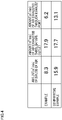
- FIG. 4 is a table showing measured values of an amount of air flowing into a duct and an amount of air flowing into a winding chamber from the duct.
- FIG. 1 is a side view of a yarn production system 1 of the present embodiment.
- front-rear and up-down directions in FIG. 1 will be referred to as front-rear and up-down directions of the yarn production system 1.
- a direction orthogonal to FIG. 1 will be referred to as a left-right direction of the yarn production system 1.
- the side close to the viewer will be referred to as a right direction.
- the yarn production system 1 includes a spinning apparatus 2, a cooling apparatus 3, a spun yarn drawing apparatus 4, a winding device 5, a duct 6, oil nozzles 7, guides 8, and godet rollers 9 and 10.
- the spinning apparatus 2, the cooling apparatus 3, the oil nozzles 7, and the guides 8 are provided in a spinning chamber 101.
- the spun yarn drawing apparatus 4, the winding device 5, the duct 6, and the godet rollers 9 and 10 are provided in a winding chamber 102 provided below the spinning chamber 101.
- the yarn production system 1 includes a partition plate 40 which separates the spinning chamber 101 from the winding chamber 102.
- the partition plate 40 forms a part of the floor surface of the spinning chamber 101 and a part of a ceiling 102b of the winding chamber 102. In the present embodiment, the distance between a floor surface 102a and the ceiling 102b in the winding chamber 102 is approximately 6 to 7 meters.
- the spinning apparatus 2 is configured to spin out yarns Y downward.
- the spinning apparatus 2 includes a spinning beam 21 configured to convey molten polymer and spinnerets 22 configured to spin out the molten polymer downward as the yarns Y.
- the spinnerets 22 are aligned in the left-right direction. Therefore, the yarns Y spun out from the spinnerets 22 are aligned in the left-right direction.
- the cooling apparatus 3 is provided below the spinning apparatus 2.
- the cooling apparatus 3 is configured to supply cooling air to the yarns Y spun out from the spinning apparatus 2 so as to cool the yarns Y.
- the cooling apparatus 3 includes a cooling cylinder 31.
- the cooling cylinder 31 is open at its both ends in the up-down direction, and is substantially cylindrical in shape.
- the yarns Y are able to run downward in the cooling cylinder 31, and the cooling apparatus 3 is configured to supply cooling air to the yarns Y running in the cooling cylinder 31.
- the oil nozzles 7 are provided below the cooling apparatus 3, and configured to apply oil to the respective yarns Y cooled by the cooling apparatus 3.
- the guides 8 are provided below the respective oil nozzles 7 at regular intervals in the left-right direction, and arranged to individually guide the yarns Y to which oil has been applied.
- the duct 6 causes the spinning chamber 101 to communicate with the winding chamber 102, and extends downward in the winding chamber 102 so as to surround the yarns Y.
- the duct 6 will be detailed later.
- front parts of the yarns Y are exposed to the spinning chamber 101 at an interval between the cooling apparatus 3 and the duct 6. Furthermore, a plate member 41 having plural holes is provided behind the yarns Y running between the cooling apparatus 3 and the duct 6. With this arrangement, at the interval between the cooling apparatus 3 and the duct 6, rear parts of the yarns Y are partially exposed to the spinning chamber 101 through the holes provided in the plate member 41. Although not illustrated, side walls are formed to the left and right of the yarns Y running between the cooling apparatus 3 and the duct 6. With this arrangement, left parts and right parts of the yarns Y are not exposed to the spinning chamber 101 at the interval between the cooling apparatus 3 and the duct 6.
- the spun yarn drawing apparatus 4 is provided below the duct 6.
- the spun yarn drawing apparatus 4 is configured to heat and draw the yarns Y by means of godet rollers (not illustrated) housed in a thermal insulation box (not illustrated).
- the yarns Y drawn by the spun yarn drawing apparatus 4 are sent to the winding device 5 via the godet rollers 9 and 10.
- the winding device 5 is configured to wind the yarns Y, and provided on the floor surface 102a of the winding chamber 102.
- the winding device 5 is configured to wind the yarns Y onto bobbins B retained by bobbin holders 11 so as to form packages P.
- the winding device 5 is provided with two bobbin holders 11.
- Each bobbin holder 11 is a shaft member extending in the front-rear direction, and is cantilevered at its rear end portion by a turret 13 provided on a frame 12.
- the bobbin holder 11 is able to retain the bobbins B which are aligned in an axial direction of the bobbin holder 11. For example, when eight yarns Y are sent from the spinning apparatus 2, the eight yarns Y are respectively wound onto eight bobbins B.
- the winding device 5 includes supporting guides 14, traverse units 15, and a contact roller 16.
- the supporting guides 14 are aligned in the front-rear direction to correspond to the bobbins B retained by the bobbin holder 11.
- the traverse units 15 are aligned in the same manner as the supporting guides 14.
- Each traverse unit 15 is configured to traverse a yarn Y in the front-rear direction about the corresponding supporting guide 14.
- the contact roller 16 makes contact with the surfaces of the packages P to adjust the shape of each package P by applying a predetermined contact pressure to each package P.
- a working area W for an operator A to perform a predetermined operation for the spun yarn drawing apparatus 4 and the winding device 5 is provided below a lower end portion of the duct 6.
- the working area W is provided for the operator A on a working bench 51 to perform a predetermined operation.
- the working bench 51 is provided on the floor surface 102a of the winding chamber 102. Examples of a predetermined operation include yarn threading to the godet rollers (not illustrated) of the spun yarn drawing apparatus 4, an unillustrated separation guide, and the like.
- the working area W is provided in front of the duct 6 (equivalent to "one side of a/the duct" of the present invention) in the axial direction of the bobbin holder 11, i.e., the front-rear direction.
- the winding device 5 is provided behind the duct 6. Therefore, the working area W is provided to oppose the winding device 5 over the duct 6.
- the duct 6 extends in the up-down direction and is substantially rectangular parallelepiped in shape.
- a cross section orthogonal to an extending direction of the duct 6 has a rectangular shape.
- the long side of the cross section extends along the left-right direction, and the short side of the cross section extends along the front-rear direction.
- An upper portion of the duct 6 is fixed by the partition plate 40.
- the duct 6 has a yarn inlet 61, a yarn outlet 62, and an exhaust port 63.
- the yarn inlet 61 is provided at an upper end portion of the duct 6, for allowing the yarns Y to be introduced into the duct 6.
- the yarn inlet 61 of the duct 6 is connected to a hole provided in the partition plate 40. The yarns Y run downward from the cooling apparatus 3 in the spinning chamber 101, and are then introduced into the duct 6 through the yarn inlet 61.
- the yarn outlet 62 is provided at the lower end portion of the duct 6, for allowing the yarns Y to be forwarded to the winding chamber 102 from the duct 6.
- the yarn outlet 62 is provided above the spun yarn drawing apparatus 4.
- the yarns Y running in the duct 6 are taken out from the duct 6 through the yarn outlet 62.
- the distance between the floor surface 102a of the winding chamber 102 and the yarn outlet 62 is approximately 3 meters.
- the exhaust port 63 provided between the yarn inlet 61 and the yarn outlet 62 is open to the winding chamber 102.
- the lower end of the exhaust port 63 is far from the floor surface 102a of the winding chamber 102 by 5 meters or more.
- the distance between the lower end of the exhaust port 63 and the partition plate 40 is equal to or less than 1 meter. In the present embodiment, the distance between the lower end of the exhaust port 63 and the partition plate 40 is 550 mm.
- the exhaust port 63 is open in a direction orthogonal to an arrangement direction of the yarns Y running in the duct 6, i.e., in the front-rear direction.
- the exhaust port 63 is open rearward (equivalent to "the other side of a/the duct" of the present invention) in the axial direction of the bobbin holder 11, i.e., in the front-rear direction of the duct 6.
- the exhaust port 63 When viewed in the direction orthogonal to the arrangement direction of the yarns Y, i.e., in the front-rear direction, the exhaust port 63 is sized to include all of the yarns Y in the left-right direction.
- the specific size of the exhaust port 63 is 250 mm in the up-down direction and 1320 mm in the left-right direction.
- the exhaust port 63 has small holes 63a.
- the diameter of each small hole 63a is 55 mm.
- four lines are aligned in the up-down direction to form four stages, and twenty two small holes 63a constituting each line are aligned in the left-right direction.
- the total number of the small holes 63a is 88.
- the air in the duct 6 is exhausted to the winding chamber 102 through each small hole 63a.
- the exhaust port 63 having all of the small holes 63a is sized to include all of the yarns Y in the left-right direction.
- the duct 6 further includes an adjustment member 64 which is able to adjust an aperture area of the exhaust port 63.
- the adjustment member 64 is provided on an inner surface of the duct 6 and above the exhaust port 63.
- the adjustment member 64 is a slidable shutter, and movable in the up-down direction.
- the size of the adjustment member 64 is slightly greater than that of the exhaust port 63 both in the up-down direction and the left-right direction.
- the adjustment member 64 covers a part of the exhaust port 63. In this way, the adjustment member 64 adjusts the aperture area of the exhaust port 63.
- an exhaust port is not provided at a lower portion of the duct 6.
- the duct 6 is not open to the winding chamber 102 except the yarn outlet 62 and the exhaust port 63.
- the high-temperature air in the duct 6 is not exhausted to the winding chamber 102 through a part of the duct 6 different from the yarn outlet 62 and the exhaust port 63. It is therefore possible to suppress inflow of the high-temperature air from the spinning chamber 101 to the working area W of the winding chamber 102 through the duct 6.
- the exhaust port 63 is arranged so that the air in the duct 6 is not sucked out in order to exhaust the air in the duct 6.
- the exhaust port 63 is simply open to the winding chamber 102. At the exhaust port 63, because the air in the duct 6 is not sucked from the outside, the pressure in the duct 6 is less likely to be negative. It is therefore possible to suppress inflow of high-temperature air from the spinning chamber 101 to the duct 6 through the yarn inlet 61.
- an amount (m 3 /mim) of air flowing into a duct was compared with an amount (m 3 /mim) of air exhausted from the duct to the winding chamber 102.
- the following amount was measured as the amount of the air flowing into the duct: an amount of air flowing into the duct through the yarn inlet from the vicinity of the front parts of the yarns Y.
- the front parts of the yarns Y are exposed to the spinning chamber 101 at the interval between the cooling apparatus 3 and the duct.
- the yarn production system 1 of Example is structured in the same manner as in the above-described embodiment.
- the adjustment member 64 does not cover the exhaust port 63 (see FIG. 2 ).
- the yarn production system 1 of Comparative Example is structured in the same manner as in Example, except a duct.
- a duct 106 of Comparative Example has a yarn inlet 161, a yarn outlet 162, and an exhaust port 163.
- This yarn inlet 161 and this yarn outlet 162 are provided in the same manner as the yarn inlet 61 and the yarn outlet 62 at the duct 6 of Example. That is, the yarn inlet 161 is connected to the partition plate 40, and the distance between the yarn outlet 162 and the floor surface 102a is 3.5 meters.
- the exhaust port 163 is provided at a lower portion of the duct 106.
- the exhaust port 163 is open rearward in the front-right direction of the duct 106.
- the size of the exhaust port 163 is the same as that of the exhaust port 63 of the duct 6 both in the up-down direction and the left-right direction.
- the exhaust port 163 has eighty eight small holes 163a each of which is 55 mm in diameter, in the same manner as the exhaust port 63.
- Example 4 As shown in FIG. 4 , while an amount of air flowing into the duct 106 is 15.9 (m 3 /mim) in Comparative Example, an amount of air flowing into the duct 6 is 8.3 (m 3 /mim) in Example. In other words, the inflow of high-temperature air from the spinning chamber 101 to the duct 6 is suppressed in Example as compared to Comparative Example. This seems to be because, in Example, the exhaust port 63 is provided to be separated from the floor surface 102a of the winding chamber 102 so as to increase the static pressure in the duct 6 and to suppress inflow of air from a part of the duct. At this part of the duct, the yarns Y are exposed.
- Example there is little difference between Example and Comparative Example in regard to the amount of the air exhausted to the winding chamber 102 through the yarn outlet 62 (yarn outlet 162). Meanwhile, an amount of the air exhausted to the winding chamber 102 thorough the exhaust port 63 in Example is smaller than an amount of the air exhausted to the winding chamber 102 through the exhaust port 163 in Comparative Example.
- the amount of the air exhausted to the winding chamber 102 through the exhaust port 63 is 6.2 (m 3 /mim) in Example, and the amount of the air exhausted to the winding chamber 102 through the exhaust port 163 is 13.1 (m 3 /mim) in Comparative Example. This seems to be because, in Example, the amount of the air exhausted through the exhaust port 63 is decreased because of the above-described suppression of an amount of air flowing into the duct 6 through the yarn inlet 61.
- the exhaust port 163 is provided at the lower portion of the duct 106 in Comparative Example, the air exhausted to the winding chamber 102 through the exhaust port 163 flows into the working area W. Meanwhile, because the exhaust port 63 is provided to be separated from the floor surface 102a in Example, the air exhausted to the winding chamber 102 through the exhaust port 63 is unlikely to flow into the working area W. Therefore, inflow of high-temperature air from the spinning chamber 101 to the working area W is suppressed in Example as compared to Comparative Example.
- the yarn production system 1 of the present embodiment includes the spinning apparatus 2 and the cooling apparatus 3 which are provided in the spinning chamber 101, the winding device 5 provided on the floor surface 102a of the winding chamber 102, the partition plate 40, and the duct 6.
- the duct 6 causes the spinning chamber 101 to communicate with the winding chamber 102, and extends downward in the winding chamber 102 so as to surround the yarns Y.
- the working area W is provided below the lower end portion of the duct 6.
- the duct 6 has the yarn inlet 61 provided for allowing the yarns Y to be introduced into the duct 6 at an upper end portion of the duct 6, the yarn outlet 62 provided for allowing the yarns Y to be taken out from the duct 6 at a lower end portion of the duct 6, and the exhaust port 63 provided between the yarn inlet 61 and the yarn outlet 62 to be open to the winding chamber 102.
- the lower end of the exhaust port 63 is far from the floor surface 102a of the winding chamber 102 by 5 meters or more.
- the lower end of the exhaust port 63 is far from the floor surface 102a of the winding chamber 102 by 5 meters or more. Therefore, a part of the high-temperature air in the duct 6 is exhausted at a position which is sufficiently far from the floor surface 102a of the winding chamber 102. This suppresses inflow of high-temperature air to the working area W through the duct 6, and thus deterioration of a working environment of the operator A is suppressed in the winding chamber 102.
- the working area W is provided to be close to the floor surface 102a of the winding chamber 102.
- the distance between the lower end of the exhaust port 63 and the partition plate 40 forming the ceiling 102b of the winding chamber 102 is equal to or less than 1 meter. Therefore, a part of the high-temperature air in the duct 6 is exhausted at a position which is close to the ceiling 102b of the winding chamber 102. This further suppresses the inflow of the high-temperature air to the working area W through the duct 6, and thus the deterioration of a working environment of the operator A is suppressed in the winding chamber 102.
- the exhaust port 63 is open in the direction (front-rear direction) orthogonal to the arrangement direction (left-right direction) of the yarns Y.
- airflow is generated. This airflow affects the quality of the yarns Y running in the duct 6.
- the exhaust port 63 is open in a direction parallel to the arrangement direction of the yarns Y, the influence of the air exhausted through the exhaust port 63 on the yarns Y is different between yarns Y on one side of the arrangement direction (the right side of the left-right direction) and yarns Y on the other side of the arrangement direction (the left side of the left-right direction). In this case, dispersion in quality of the yarns Y may occur.
- the exhaust port 63 is open in the direction orthogonal to the arrangement direction of the yarns Y. Therefore, the influence of the air exhausted through the exhaust port 63 on the yarns Y on one side of the arrangement direction (the right side of the left-right direction) is substantially equal to that on the yarns Y on the other side of the arrangement direction (the left side of the left-right direction). This suppresses the dispersion in quality of the yarns Y.
- the exhaust port 63 when viewed in the direction (front-rear direction) orthogonal to the arrangement direction (left-right direction) of the yarns Y, the exhaust port 63 is sized to include all of the yarns Y in the arrangement direction (left-right direction). In the present embodiment, as compared to a case where the exhaust port 63 is sized to include only some of the yarns Y in the left-right direction when viewed in the front-rear direction, the influence of the air exhausted through the exhaust port 63 is further equalized between the yarns Y. This further suppresses the dispersion in quality of the yarns Y.
- the working area W is provided in front of the duct 6 in the axial direction (front-rear direction) of the bobbin holder 11. Furthermore, the exhaust port 63 at the duct 6 is open rearward in the axial direction (front-rear direction) of the bobbin holder 11. In the present embodiment, through the exhaust port 63, a part of the high-temperature air in the duct 6 is exhausted to the side opposite to the working area W where the operator A performs a predetermined operation over the duct 6. It is therefore possible to exhaust high-temperature air toward a position which is far from the working area W. This further suppresses the inflow of high-temperature air to the working area W.
- the yarns Y are exposed to the spinning chamber 101 at the part of between the cooling apparatus 3 and the duct 6.
- a large amount of high-temperature air flows into the duct 6 from the vicinity of the exposed yarns Y.
- the exhaust port 63 is provided to be separated from the floor surface 102a of the winding chamber 102 in the present embodiment, (i) increase of the static pressure in the duct 6 and (ii) inflow of high-temperature air from the vicinity of the exposed yarns Y to the duct 6 are suppressed. This further suppresses the inflow of the high-temperature air to the working area W through the duct 6.
- the duct 6 further includes the adjustment member 64 which is able to adjust the aperture area of the exhaust port 63.
- the aperture area of the exhaust port 63 is adjustable. Therefore, the aperture area of the exhaust port 63 is suitably adjustable to be a value at which inflow of high-temperature air to the working area W is suppressed most effectively.
- This adjustment is performed in consideration of balance between the high-temperature air flowing into the duct 6 through the yarn inlet 61 and the high-temperature air exhausted to the winding chamber 102 through the exhaust port 63 and in accordance with areas of the spinning chamber 101 and the winding chamber 102.
- an arrangement direction of the spinnerets 22 is orthogonal to the axial direction of the bobbin holder 11.
- the exhaust port 63 is open in the direction orthogonal to the arrangement direction of the yarns Y and at the same time in the axial direction of the bobbin holder 11.
- the yarn production system 1 may be structured so that the arrangement direction of the spinnerets 22 is parallel to the axial direction of the bobbin holder 11.
- the exhaust port 63 may be open in the direction orthogonal to the arrangement direction of the yarns Y and at the same time in a direction orthogonal to the axial direction of the bobbin holder 11.
- the exhaust port 63 may be open in the direction parallel to the arrangement direction of the yarns Y and at the same time in the axial direction of the bobbin holder 11.
- the exhaust port 63 is open rearward and toward the winding chamber 102 in the direction orthogonal to the arrangement direction of the yarns Y.
- the exhaust port 63 is open at a rear surface of the duct 6.
- the exhaust port 63 may be open at any one of side surfaces of the duct 6, or plural exhaust port may be open at two or more of the side surfaces.
- the distance between the lower end of the exhaust port 63 and the partition plate 40 is equal to or less than 1 meter.
- the distance between the lower end of the exhaust port 63 and the partition plate 40 may be larger than 1 meter.
- the exhaust port 63 is provided so that the lower end of the exhaust port 63 is far from the floor surface 102a of the winding chamber 102 by 5 meters or more.
- the exhaust port 63 may not have the small holes 63a.
- the exhaust port 63 is a single opening.
- an opening which is sized not to disturb the exhaust of air through the exhaust port 63 may be additionally provided at any part of the duct 6.
- the yarn inlet 61 of the duct 6 is connected to the partition plate 40.
- the yarn inlet 61 may be provided above the partition plate 40.
- the cross section orthogonal to the extending direction of the duct 6 may be circular or elliptical in shape.
- the duct 6 may be curbed at its intermediate part.
- the yarns Y are exposed to the spinning chamber 101 at the interval between the cooling apparatus 3 and the duct 6.
- the yarns Y may not be exposed to the spinning chamber 101 at the interval between the cooling apparatus 3 and the duct 6.
- a lower end of the cooling apparatus 3 may be directly connected to an upper end of the duct 6.
- the right parts and left parts of the yarns Y may be exposed to the spinning chamber 101 at the interval between the cooling apparatus 3 and the duct 6.
- influence of air flowing from the vicinity of the exposed yarns Y in the spinning chamber 101 may not be equalized between the yarns Y. Therefore, the left and right sides of the yarns Y in the left-right direction parallel to the arrangement direction of the yarns Y are preferably closed, and the front parts, the rear parts, or the front and rear parts of the yarns Y in the front-rear direction orthogonal to the arrangement direction of the yarns Y are preferably exposed to the spinning chamber 101.
- the adjustment member 64 is a slidable shutter which is movable in the up-down direction.
- the adjustment member 64 may be a slidable shutter which is movable in the left-right direction.
- the adjustment member 64 is not limited to a slidable shutter.
- the adjustment member 64 may be a member which is attachable to and detachable from the exhaust port 63. In the embodiment above, the adjustment member 64 may not be provided.
- the working area W is provided in front of the duct 6.
- the working area W may be provided to the right of, to the left of, behind, to the right of and in front of, to the left of and in front of, to the right of and behind, or to the left of and behind the duct 6.
- the working area W may be provided in an area covering two or more of the following locations: to the right of, to the left of, behind, to the right of and in front of, to the left of and in front of, to the right of and behind, or to the left of and behind the duct 6.
- the working bench 51 may not be provided.
- the working area W is defined as an area provided for the operator A on the floor surface 102a to perform a predetermined operation.
- examples of a predetermined operation may include yarn threading of the yarns Y to the godet rollers 9 and 10, the winding device 5, and the supporting guides 14, and replacement of the bobbins B attached to the bobbin holder 11 of the winding device 5.
- the working area W may not be provided on the working bench 51.
- the working area W may be provided on the floor surface 102a and centered on the duct 6 when viewed in the up-down direction, or may be provided around the working bench 51.
Landscapes
- Engineering & Computer Science (AREA)
- Mechanical Engineering (AREA)
- Textile Engineering (AREA)
- Spinning Methods And Devices For Manufacturing Artificial Fibers (AREA)
- Yarns And Mechanical Finishing Of Yarns Or Ropes (AREA)
Abstract
Description
- The present invention relates to a yarn production system including a duct which surrounds a running yarn.
- A known yarn production system includes: a spinning apparatus configured to spin out hot molten polymer downward from a spinneret as a yarn; a cooler configured to supply cooling air to the yarn spun out from the spinning apparatus; and a winding device which is provided below the cooler and which is configured to wind the yarn onto a bobbin attached to a bobbin holder. The spinning apparatus and the cooler are provided in a spinning chamber, and the winding device is provided on the floor surface of a winding chamber provided below the spinning chamber.
- The yarn running between the cooler in the spinning chamber and the winding device in the winding chamber is exposed to the outside air. Because of this, yarn swing may occur. As a result, yarn threading to the winding device may not be properly performed and the quality of the running yarn may be decreased. Therefore, a duct which surrounds the running yarn in order to suppress the yarn swing is provided between the cooler in the spinning chamber and the winding device in the winding chamber.
- Patent Literature 1 (
Japanese Laid-Open Patent Publication No. S50-118013 - A spinning apparatus is provided with a spinning beam which is configured to convey hot molten polymer while the temperature of the hot molten polymer is maintained, and to spin out yarns. Because of heat radiation from this spinning beam, high-temperature air is generated in a spinning chamber. In addition to that, the high-temperature air is generated also by heat exchange between (i) cooling air supplied to the yarns by a cooler and (ii) the hot molten polymer. Such high-temperature air in the spinning chamber flows downward along with the yarns running in the duct, and is exhausted to a winding chamber through a yarn outlet and an exhaust port.
- In the vicinity of a winding device provided on the floor surface of a winding chamber of a yarn production system of Patent Literature 1, a working area is provided for an operator to perform various types of operations such as yarn threading to the winding device. When an exhaust port of a duct is provided to be close to the working area, high-temperature air disadvantageously flows into the working area through a yarn outlet and the exhaust port. This increases the temperature of the working area, and thus a working environment of the operator is deteriorated.
- An object of the present invention is to suppress the deterioration of a working environment of an operator in a winding chamber due to the high-temperature air of a spinning chamber, which flows into the winding chamber through a duct.
- A yarn production system of the present invention includes: a spinning apparatus which is provided in a spinning chamber and is configured to spin out yarns downward; a winding device which is provided on a floor surface of a winding chamber and is configured to wind the yarns spun out from the spinning apparatus onto bobbins attached to a bobbin holder, the winding chamber being provided below the spinning chamber; a partition plate which separates the spinning chamber from the winding chamber and forms the floor surface of the spinning chamber and a ceiling of the winding chamber; and a duct which causes the spinning chamber to communicate with the winding chamber and extends downward in the winding chamber so as to surround the yarns, and a working area is provided below a lower end portion of the duct to allow an operator to perform a predetermined operation for the winding device. In this yarn production system, the duct has: a yarn inlet provided at an upper end portion of the duct for allowing the yarns to be introduced into the duct; a yarn outlet provided at the lower end portion of the duct for allowing the yarns to be taken out from the duct; and an exhaust port provided between the yarn inlet and the yarn outlet to be open to the winding chamber, and a lower end of the exhaust port is provided to be separated from the floor surface of the winding chamber by 5 meters or more.
- According to the present invention, the lower end of the exhaust port is separated from the floor surface of the winding chamber by 5 meters or more. Therefore, a part of the high-temperature air in the duct is exhausted at a position which is sufficiently far from the floor surface of the winding chamber. This suppresses inflow of high-temperature air to the working area through the duct, and thus deterioration of a working environment of the operator is suppressed in the winding chamber. In this regard, the working area is provided to be close to the floor surface of the winding chamber.
- In the present invention, a distance between the lower end of the exhaust port and the partition plate is preferably equal to or less than 1 meter.
- According to the present invention, the distance between the lower end of the exhaust port and the partition plate forming the ceiling of the winding chamber is equal to or less than 1 meter. Therefore, a part of the high-temperature air in the duct is exhausted at a position which is close to the ceiling of the winding chamber. This further suppresses the inflow of the high-temperature air to the working area through the duct, and thus the deterioration of a working environment of the operator is suppressed in the winding chamber.
- In the present invention, the exhaust port is preferably open in a direction orthogonal to an arrangement direction of the yarns.
- When air is exhausted through the exhaust port, airflow is generated. This airflow affects the quality of the yarns running in the duct. When the exhaust port is open in a direction parallel to the arrangement direction of the yarns, the influence of the air exhausted through the exhaust port on the yarns is different between yarns on one side of the arrangement direction and yarns on the other side of the arrangement direction. In this case, dispersion in quality of the yarns may occur. According to the present invention, the exhaust port is open in the direction orthogonal to the arrangement direction of the yarns. Therefore, the influence of the air exhausted through the exhaust port on the yarns on one side of the arrangement direction is substantially equal to that on the yarns on the other side of the arrangement direction. This suppresses the dispersion in quality of the yarns.
- In the present invention, the exhaust port is preferably sized to include all of the yarns in the arrangement direction when viewed in the direction orthogonal to the arrangement direction.
- According to the present invention, as compared to a case where the exhaust port is sized to include only some of the yarns in the arrangement direction when viewed in the direction orthogonal to the arrangement direction, the influence of the air exhausted through the exhaust port is further equalized between the yarns. This further suppresses the dispersion in quality of the yarns.
- In the present invention, the working area is preferably provided on one side of the duct in an axial direction of the bobbin holder, and the exhaust port is open to the other side of the duct in the axial direction of the bobbin holder.
- According to the present invention, through the exhaust port, a part of the high-temperature air in the duct is exhausted to the side opposite to the working area where the operator performs a predetermined operation over the duct. It is therefore possible to exhaust high-temperature air toward a position which is far from the working area. This further suppresses inflow of high-temperature air to the working area.
- In the present invention, the yarns are preferably exposed to the spinning chamber at an interval between the duct and a cooling apparatus which is provided below the spinning apparatus in the spinning chamber and is configured to supply cooling air to the yarns spun out from the spinning apparatus.
- When the yarns are exposed to the spinning chamber at the interval between the duct and the cooling apparatus, a large amount of high-temperature air flows into the duct from the vicinity of the exposed yarns through the yarn inlet. In this regard, the exhaust port is far from the floor surface of the winding chamber according to the present invention. With this arrangement, as compared to a case where the exhaust port is close to the floor surface of the winding chamber, resistance is large at the lower portion of the duct and the static pressure in the duct is increased. As a result, inflow of high-temperature air into the duct through the yarn inlet is suppressed. This further suppresses the inflow of the high-temperature air to the working area through the duct.
- In the present invention, preferably, the duct further has an adjustment member which is able to adjust an aperture area of the exhaust port.
- The larger the aperture area of the exhaust port is, the larger an amount of high-temperature air which can be exhausted through the exhaust port is. Meanwhile, when the aperture area of the exhaust port is large, the pressure in the duct is decreased because air is exhausted through the exhaust port. As a result, an amount of high-temperature air which flows into the duct through the yarn inlet is also large. The following amounts in a case where the exhaust port is adjusted so as to obtain a predetermined aperture area are determined by the spinning speed, the type of the yarns, and the like: an amount of high-temperature air flowing into the duct through the yarn inlet; and an amount of high-temperature air exhausted through the exhaust port. According to the present invention, the aperture area of the exhaust port is adjustable. Therefore, the aperture area of the exhaust port is suitably adjustable to be a value at which inflow of high-temperature air to the working area is suppressed most effectively. This adjustment is performed in consideration of balance between the high-temperature air flowing into the duct through the yarn inlet and the high-temperature air exhausted to the winding chamber through the exhaust port and in accordance with how large the spinning chamber is and how large the winding chamber is.
-
-
FIG. 1 is a side view of a yarn production system of an embodiment. -
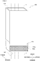
FIG. 2 illustrates a duct of the present embodiment. -
FIG. 3 illustrates a duct of Comparative Example. - In regard to each of Example and Comparative Example,
FIG. 4 is a table showing measured values of an amount of air flowing into a duct and an amount of air flowing into a winding chamber from the duct. - The following will describe an embodiment of the present invention with reference to figures.
FIG. 1 is a side view of a yarn production system 1 of the present embodiment. Hereinafter, front-rear and up-down directions inFIG. 1 will be referred to as front-rear and up-down directions of the yarn production system 1. Furthermore, a direction orthogonal toFIG. 1 will be referred to as a left-right direction of the yarn production system 1. In this regard, the side close to the viewer will be referred to as a right direction. - As shown in
FIG. 1 , the yarn production system 1 includes aspinning apparatus 2, acooling apparatus 3, a spunyarn drawing apparatus 4, a windingdevice 5, aduct 6,oil nozzles 7, guides 8, andgodet rollers 9 and 10. Thespinning apparatus 2, thecooling apparatus 3, theoil nozzles 7, and theguides 8 are provided in aspinning chamber 101. The spunyarn drawing apparatus 4, the windingdevice 5, theduct 6, and thegodet rollers 9 and 10 are provided in a windingchamber 102 provided below the spinningchamber 101. The yarn production system 1 includes apartition plate 40 which separates the spinningchamber 101 from the windingchamber 102. Thepartition plate 40 forms a part of the floor surface of thespinning chamber 101 and a part of aceiling 102b of the windingchamber 102. In the present embodiment, the distance between afloor surface 102a and theceiling 102b in the windingchamber 102 is approximately 6 to 7 meters. - The
spinning apparatus 2 is configured to spin out yarns Y downward. Thespinning apparatus 2 includes aspinning beam 21 configured to convey molten polymer andspinnerets 22 configured to spin out the molten polymer downward as the yarns Y. Thespinnerets 22 are aligned in the left-right direction. Therefore, the yarns Y spun out from thespinnerets 22 are aligned in the left-right direction. - The
cooling apparatus 3 is provided below thespinning apparatus 2. Thecooling apparatus 3 is configured to supply cooling air to the yarns Y spun out from thespinning apparatus 2 so as to cool the yarns Y. Thecooling apparatus 3 includes acooling cylinder 31. The coolingcylinder 31 is open at its both ends in the up-down direction, and is substantially cylindrical in shape. The yarns Y are able to run downward in thecooling cylinder 31, and thecooling apparatus 3 is configured to supply cooling air to the yarns Y running in thecooling cylinder 31. - The
oil nozzles 7 are provided below thecooling apparatus 3, and configured to apply oil to the respective yarns Y cooled by thecooling apparatus 3. Theguides 8 are provided below therespective oil nozzles 7 at regular intervals in the left-right direction, and arranged to individually guide the yarns Y to which oil has been applied. - The
duct 6 causes thespinning chamber 101 to communicate with the windingchamber 102, and extends downward in the windingchamber 102 so as to surround the yarns Y. Theduct 6 will be detailed later. - In the present embodiment, front parts of the yarns Y are exposed to the
spinning chamber 101 at an interval between thecooling apparatus 3 and theduct 6. Furthermore, aplate member 41 having plural holes is provided behind the yarns Y running between thecooling apparatus 3 and theduct 6. With this arrangement, at the interval between thecooling apparatus 3 and theduct 6, rear parts of the yarns Y are partially exposed to thespinning chamber 101 through the holes provided in theplate member 41. Although not illustrated, side walls are formed to the left and right of the yarns Y running between thecooling apparatus 3 and theduct 6. With this arrangement, left parts and right parts of the yarns Y are not exposed to thespinning chamber 101 at the interval between thecooling apparatus 3 and theduct 6. - Between the
cooling apparatus 3 and theduct 6, front parts of theoil nozzles 7 and those of theguides 8 are exposed to thespinning chamber 101 in the same manner as the yarns Y. Furthermore, between thecooling apparatus 3 and theduct 6, rear parts of theoil nozzles 7 and those of theguides 8 are partially exposed to thespinning chamber 101 through the holes provided in theplate member 41. Between thecooling apparatus 3 and theduct 6, left parts and right parts of theoil nozzles 7 and those of theguides 8 are not exposed to thespinning chamber 101. - The spun
yarn drawing apparatus 4 is provided below theduct 6. The spunyarn drawing apparatus 4 is configured to heat and draw the yarns Y by means of godet rollers (not illustrated) housed in a thermal insulation box (not illustrated). - The yarns Y drawn by the spun
yarn drawing apparatus 4 are sent to the windingdevice 5 via thegodet rollers 9 and 10. The windingdevice 5 is configured to wind the yarns Y, and provided on thefloor surface 102a of the windingchamber 102. - The winding
device 5 is configured to wind the yarns Y onto bobbins B retained bybobbin holders 11 so as to form packages P. The windingdevice 5 is provided with twobobbin holders 11. Eachbobbin holder 11 is a shaft member extending in the front-rear direction, and is cantilevered at its rear end portion by aturret 13 provided on aframe 12. Thebobbin holder 11 is able to retain the bobbins B which are aligned in an axial direction of thebobbin holder 11. For example, when eight yarns Y are sent from thespinning apparatus 2, the eight yarns Y are respectively wound onto eight bobbins B. - The winding
device 5 includes supportingguides 14, traverseunits 15, and acontact roller 16. The supporting guides 14 are aligned in the front-rear direction to correspond to the bobbins B retained by thebobbin holder 11. Thetraverse units 15 are aligned in the same manner as the supporting guides 14. Eachtraverse unit 15 is configured to traverse a yarn Y in the front-rear direction about the corresponding supportingguide 14. Thecontact roller 16 makes contact with the surfaces of the packages P to adjust the shape of each package P by applying a predetermined contact pressure to each package P. - As shown in
FIG. 1 , a working area W for an operator A to perform a predetermined operation for the spunyarn drawing apparatus 4 and the windingdevice 5 is provided below a lower end portion of theduct 6. The working area W is provided for the operator A on a workingbench 51 to perform a predetermined operation. The workingbench 51 is provided on thefloor surface 102a of the windingchamber 102. Examples of a predetermined operation include yarn threading to the godet rollers (not illustrated) of the spunyarn drawing apparatus 4, an unillustrated separation guide, and the like. - The working area W is provided in front of the duct 6 (equivalent to "one side of a/the duct" of the present invention) in the axial direction of the
bobbin holder 11, i.e., the front-rear direction. In the present embodiment, the windingdevice 5 is provided behind theduct 6. Therefore, the working area W is provided to oppose the windingdevice 5 over theduct 6. - The following will detail the
duct 6. As shown inFIG. 1 andFIG. 2 , theduct 6 extends in the up-down direction and is substantially rectangular parallelepiped in shape. A cross section orthogonal to an extending direction of theduct 6 has a rectangular shape. The long side of the cross section extends along the left-right direction, and the short side of the cross section extends along the front-rear direction. An upper portion of theduct 6 is fixed by thepartition plate 40. As shown inFIG. 1 andFIG. 2 , theduct 6 has ayarn inlet 61, ayarn outlet 62, and anexhaust port 63. - The
yarn inlet 61 is provided at an upper end portion of theduct 6, for allowing the yarns Y to be introduced into theduct 6. Theyarn inlet 61 of theduct 6 is connected to a hole provided in thepartition plate 40. The yarns Y run downward from thecooling apparatus 3 in thespinning chamber 101, and are then introduced into theduct 6 through theyarn inlet 61. - The
yarn outlet 62 is provided at the lower end portion of theduct 6, for allowing the yarns Y to be forwarded to the windingchamber 102 from theduct 6. Theyarn outlet 62 is provided above the spunyarn drawing apparatus 4. The yarns Y running in theduct 6 are taken out from theduct 6 through theyarn outlet 62. The distance between thefloor surface 102a of the windingchamber 102 and theyarn outlet 62 is approximately 3 meters. - As shown in
FIG. 1 , theexhaust port 63 provided between theyarn inlet 61 and theyarn outlet 62 is open to the windingchamber 102. The lower end of theexhaust port 63 is far from thefloor surface 102a of the windingchamber 102 by 5 meters or more. The distance between the lower end of theexhaust port 63 and thepartition plate 40 is equal to or less than 1 meter. In the present embodiment, the distance between the lower end of theexhaust port 63 and thepartition plate 40 is 550 mm. Theexhaust port 63 is open in a direction orthogonal to an arrangement direction of the yarns Y running in theduct 6, i.e., in the front-rear direction. To be more specific, theexhaust port 63 is open rearward (equivalent to "the other side of a/the duct" of the present invention) in the axial direction of thebobbin holder 11, i.e., in the front-rear direction of theduct 6. - When viewed in the direction orthogonal to the arrangement direction of the yarns Y, i.e., in the front-rear direction, the
exhaust port 63 is sized to include all of the yarns Y in the left-right direction. In the present embodiment, the specific size of theexhaust port 63 is 250 mm in the up-down direction and 1320 mm in the left-right direction. - As shown in
FIG. 2 , theexhaust port 63 hassmall holes 63a. The diameter of eachsmall hole 63a is 55 mm. As shown inFIG. 2 , four lines are aligned in the up-down direction to form four stages, and twenty twosmall holes 63a constituting each line are aligned in the left-right direction. The total number of thesmall holes 63a is 88. The air in theduct 6 is exhausted to the windingchamber 102 through eachsmall hole 63a. In the present embodiment, when viewed in the front-rear direction, theexhaust port 63 having all of thesmall holes 63a is sized to include all of the yarns Y in the left-right direction. - As shown in
FIG. 2 , theduct 6 further includes anadjustment member 64 which is able to adjust an aperture area of theexhaust port 63. Theadjustment member 64 is provided on an inner surface of theduct 6 and above theexhaust port 63. Theadjustment member 64 is a slidable shutter, and movable in the up-down direction. The size of theadjustment member 64 is slightly greater than that of theexhaust port 63 both in the up-down direction and the left-right direction. As a result of movement downward from a state inFIG. 2 , theadjustment member 64 covers a part of theexhaust port 63. In this way, theadjustment member 64 adjusts the aperture area of theexhaust port 63. - In the present embodiment, an exhaust port is not provided at a lower portion of the
duct 6. To be more specific, theduct 6 is not open to the windingchamber 102 except theyarn outlet 62 and theexhaust port 63. In other words, the high-temperature air in theduct 6 is not exhausted to the windingchamber 102 through a part of theduct 6 different from theyarn outlet 62 and theexhaust port 63. It is therefore possible to suppress inflow of the high-temperature air from the spinningchamber 101 to the working area W of the windingchamber 102 through theduct 6. In the present embodiment, theexhaust port 63 is arranged so that the air in theduct 6 is not sucked out in order to exhaust the air in theduct 6. In other words, theexhaust port 63 is simply open to the windingchamber 102. At theexhaust port 63, because the air in theduct 6 is not sucked from the outside, the pressure in theduct 6 is less likely to be negative. It is therefore possible to suppress inflow of high-temperature air from the spinningchamber 101 to theduct 6 through theyarn inlet 61. - In each of the yarn production system 1 of Example and a yarn production system 1 of Comparative Example, an amount (m3/mim) of air flowing into a duct was compared with an amount (m3/mim) of air exhausted from the duct to the winding
chamber 102. The following amount was measured as the amount of the air flowing into the duct: an amount of air flowing into the duct through the yarn inlet from the vicinity of the front parts of the yarns Y. The front parts of the yarns Y are exposed to thespinning chamber 101 at the interval between thecooling apparatus 3 and the duct. Each of the following amounts was measured as the amount of the air exhausted from the duct to the winding chamber 102: an amount of air exhausted to the windingchamber 102 through the yarn outlet; and an amount of air exhausted to the windingchamber 102 through an exhaust port. The measurement results are shown inFIG. 4 . - The yarn production system 1 of Example is structured in the same manner as in the above-described embodiment. In Example, the
adjustment member 64 does not cover the exhaust port 63 (seeFIG. 2 ). - The yarn production system 1 of Comparative Example is structured in the same manner as in Example, except a duct. As shown in
FIG. 3 , aduct 106 of Comparative Example has ayarn inlet 161, ayarn outlet 162, and anexhaust port 163. Thisyarn inlet 161 and thisyarn outlet 162 are provided in the same manner as theyarn inlet 61 and theyarn outlet 62 at theduct 6 of Example. That is, theyarn inlet 161 is connected to thepartition plate 40, and the distance between theyarn outlet 162 and thefloor surface 102a is 3.5 meters. Theexhaust port 163 is provided at a lower portion of theduct 106. Theexhaust port 163 is open rearward in the front-right direction of theduct 106. The size of theexhaust port 163 is the same as that of theexhaust port 63 of theduct 6 both in the up-down direction and the left-right direction. Theexhaust port 163 has eighty eightsmall holes 163a each of which is 55 mm in diameter, in the same manner as theexhaust port 63. - As shown in
FIG. 4 , while an amount of air flowing into theduct 106 is 15.9 (m3/mim) in Comparative Example, an amount of air flowing into theduct 6 is 8.3 (m3/mim) in Example. In other words, the inflow of high-temperature air from the spinningchamber 101 to theduct 6 is suppressed in Example as compared to Comparative Example. This seems to be because, in Example, theexhaust port 63 is provided to be separated from thefloor surface 102a of the windingchamber 102 so as to increase the static pressure in theduct 6 and to suppress inflow of air from a part of the duct. At this part of the duct, the yarns Y are exposed. - As shown in
FIG. 4 , there is little difference between Example and Comparative Example in regard to the amount of the air exhausted to the windingchamber 102 through the yarn outlet 62 (yarn outlet 162). Meanwhile, an amount of the air exhausted to the windingchamber 102 thorough theexhaust port 63 in Example is smaller than an amount of the air exhausted to the windingchamber 102 through theexhaust port 163 in Comparative Example. To be more specific, the amount of the air exhausted to the windingchamber 102 through theexhaust port 63 is 6.2 (m3/mim) in Example, and the amount of the air exhausted to the windingchamber 102 through theexhaust port 163 is 13.1 (m3/mim) in Comparative Example. This seems to be because, in Example, the amount of the air exhausted through theexhaust port 63 is decreased because of the above-described suppression of an amount of air flowing into theduct 6 through theyarn inlet 61. - Because the
exhaust port 163 is provided at the lower portion of theduct 106 in Comparative Example, the air exhausted to the windingchamber 102 through theexhaust port 163 flows into the working area W. Meanwhile, because theexhaust port 63 is provided to be separated from thefloor surface 102a in Example, the air exhausted to the windingchamber 102 through theexhaust port 63 is unlikely to flow into the working area W. Therefore, inflow of high-temperature air from the spinningchamber 101 to the working area W is suppressed in Example as compared to Comparative Example. - The yarn production system 1 of the present embodiment includes the
spinning apparatus 2 and thecooling apparatus 3 which are provided in thespinning chamber 101, the windingdevice 5 provided on thefloor surface 102a of the windingchamber 102, thepartition plate 40, and theduct 6. Theduct 6 causes thespinning chamber 101 to communicate with the windingchamber 102, and extends downward in the windingchamber 102 so as to surround the yarns Y. The working area W is provided below the lower end portion of theduct 6. Theduct 6 has theyarn inlet 61 provided for allowing the yarns Y to be introduced into theduct 6 at an upper end portion of theduct 6, theyarn outlet 62 provided for allowing the yarns Y to be taken out from theduct 6 at a lower end portion of theduct 6, and theexhaust port 63 provided between theyarn inlet 61 and theyarn outlet 62 to be open to the windingchamber 102. The lower end of theexhaust port 63 is far from thefloor surface 102a of the windingchamber 102 by 5 meters or more. - In the present embodiment, the lower end of the
exhaust port 63 is far from thefloor surface 102a of the windingchamber 102 by 5 meters or more. Therefore, a part of the high-temperature air in theduct 6 is exhausted at a position which is sufficiently far from thefloor surface 102a of the windingchamber 102. This suppresses inflow of high-temperature air to the working area W through theduct 6, and thus deterioration of a working environment of the operator A is suppressed in the windingchamber 102. In this regard, the working area W is provided to be close to thefloor surface 102a of the windingchamber 102. - In the present embodiment, the distance between the lower end of the
exhaust port 63 and thepartition plate 40 forming theceiling 102b of the windingchamber 102 is equal to or less than 1 meter. Therefore, a part of the high-temperature air in theduct 6 is exhausted at a position which is close to theceiling 102b of the windingchamber 102. This further suppresses the inflow of the high-temperature air to the working area W through theduct 6, and thus the deterioration of a working environment of the operator A is suppressed in the windingchamber 102. - In the present embodiment, the
exhaust port 63 is open in the direction (front-rear direction) orthogonal to the arrangement direction (left-right direction) of the yarns Y. When air is exhausted through theexhaust port 63, airflow is generated. This airflow affects the quality of the yarns Y running in theduct 6. When theexhaust port 63 is open in a direction parallel to the arrangement direction of the yarns Y, the influence of the air exhausted through theexhaust port 63 on the yarns Y is different between yarns Y on one side of the arrangement direction (the right side of the left-right direction) and yarns Y on the other side of the arrangement direction (the left side of the left-right direction). In this case, dispersion in quality of the yarns Y may occur. In the present embodiment, theexhaust port 63 is open in the direction orthogonal to the arrangement direction of the yarns Y. Therefore, the influence of the air exhausted through theexhaust port 63 on the yarns Y on one side of the arrangement direction (the right side of the left-right direction) is substantially equal to that on the yarns Y on the other side of the arrangement direction (the left side of the left-right direction). This suppresses the dispersion in quality of the yarns Y. - In the present embodiment, when viewed in the direction (front-rear direction) orthogonal to the arrangement direction (left-right direction) of the yarns Y, the
exhaust port 63 is sized to include all of the yarns Y in the arrangement direction (left-right direction). In the present embodiment, as compared to a case where theexhaust port 63 is sized to include only some of the yarns Y in the left-right direction when viewed in the front-rear direction, the influence of the air exhausted through theexhaust port 63 is further equalized between the yarns Y. This further suppresses the dispersion in quality of the yarns Y. - In the present embodiment, the working area W is provided in front of the
duct 6 in the axial direction (front-rear direction) of thebobbin holder 11. Furthermore, theexhaust port 63 at theduct 6 is open rearward in the axial direction (front-rear direction) of thebobbin holder 11. In the present embodiment, through theexhaust port 63, a part of the high-temperature air in theduct 6 is exhausted to the side opposite to the working area W where the operator A performs a predetermined operation over theduct 6. It is therefore possible to exhaust high-temperature air toward a position which is far from the working area W. This further suppresses the inflow of high-temperature air to the working area W. - In the present embodiment, the yarns Y are exposed to the
spinning chamber 101 at the part of between thecooling apparatus 3 and theduct 6. When the yarns Y are exposed to thespinning chamber 101 at the part of between thecooling apparatus 3 and theduct 6, a large amount of high-temperature air flows into theduct 6 from the vicinity of the exposed yarns Y. In this regard, because theexhaust port 63 is provided to be separated from thefloor surface 102a of the windingchamber 102 in the present embodiment, (i) increase of the static pressure in theduct 6 and (ii) inflow of high-temperature air from the vicinity of the exposed yarns Y to theduct 6 are suppressed. This further suppresses the inflow of the high-temperature air to the working area W through theduct 6. - In the present embodiment, the
duct 6 further includes theadjustment member 64 which is able to adjust the aperture area of theexhaust port 63. The larger the aperture area of theexhaust port 63 is, the larger an amount of high-temperature air which can be exhausted through theexhaust port 63 is. Meanwhile, when the aperture area of theexhaust port 63 is large, the pressure in theduct 6 is decreased because air is exhausted through theexhaust port 63. As a result, an amount of high-temperature air which flows into theduct 6 through theyarn inlet 61 is also large. The following amounts in a case where theexhaust port 63 has a predetermined portion of the aperture area are determined by, e.g., portions of thespinning chamber 101 and the winding chamber 102: an amount of high-temperature air flowing into theduct 6 through theyarn inlet 61; and an amount of high-temperature air exhausted through theexhaust port 63. In the present embodiment, the aperture area of theexhaust port 63 is adjustable. Therefore, the aperture area of theexhaust port 63 is suitably adjustable to be a value at which inflow of high-temperature air to the working area W is suppressed most effectively. This adjustment is performed in consideration of balance between the high-temperature air flowing into theduct 6 through theyarn inlet 61 and the high-temperature air exhausted to the windingchamber 102 through theexhaust port 63 and in accordance with areas of thespinning chamber 101 and the windingchamber 102. - The following will describe modifications of the above-described embodiment. The members identical with those in the embodiment above will be denoted by the same reference numerals, and the explanations thereof are not repeated.
- In the yarn production system 1 of the embodiment above, an arrangement direction of the
spinnerets 22 is orthogonal to the axial direction of thebobbin holder 11. Theexhaust port 63 is open in the direction orthogonal to the arrangement direction of the yarns Y and at the same time in the axial direction of thebobbin holder 11. However, the yarn production system 1 may be structured so that the arrangement direction of thespinnerets 22 is parallel to the axial direction of thebobbin holder 11. In this case, theexhaust port 63 may be open in the direction orthogonal to the arrangement direction of the yarns Y and at the same time in a direction orthogonal to the axial direction of thebobbin holder 11. Alternatively, theexhaust port 63 may be open in the direction parallel to the arrangement direction of the yarns Y and at the same time in the axial direction of thebobbin holder 11. - In the embodiment above, the
exhaust port 63 is open rearward and toward the windingchamber 102 in the direction orthogonal to the arrangement direction of the yarns Y. In other words, theexhaust port 63 is open at a rear surface of theduct 6. However, theexhaust port 63 may be open at any one of side surfaces of theduct 6, or plural exhaust port may be open at two or more of the side surfaces. - In the embodiment above, the distance between the lower end of the
exhaust port 63 and thepartition plate 40 is equal to or less than 1 meter. However, the distance between the lower end of theexhaust port 63 and thepartition plate 40 may be larger than 1 meter. In this case, theexhaust port 63 is provided so that the lower end of theexhaust port 63 is far from thefloor surface 102a of the windingchamber 102 by 5 meters or more. - In the embodiment above, the
exhaust port 63 may not have thesmall holes 63a. In this case, for example, theexhaust port 63 is a single opening. In the embodiment above, an opening which is sized not to disturb the exhaust of air through theexhaust port 63 may be additionally provided at any part of theduct 6. - In the embodiment above, the
yarn inlet 61 of theduct 6 is connected to thepartition plate 40. However, theyarn inlet 61 may be provided above thepartition plate 40. - In the embodiment above, the cross section orthogonal to the extending direction of the
duct 6 may be circular or elliptical in shape. Theduct 6 may be curbed at its intermediate part. - In the embodiment above, the yarns Y are exposed to the
spinning chamber 101 at the interval between thecooling apparatus 3 and theduct 6. However, the yarns Y may not be exposed to thespinning chamber 101 at the interval between thecooling apparatus 3 and theduct 6. In this case, for example, a lower end of thecooling apparatus 3 may be directly connected to an upper end of theduct 6. - The right parts and left parts of the yarns Y may be exposed to the
spinning chamber 101 at the interval between thecooling apparatus 3 and theduct 6. However, when the right parts and left parts of the yarns Y are exposed to thespinning chamber 101, influence of air flowing from the vicinity of the exposed yarns Y in thespinning chamber 101 may not be equalized between the yarns Y. Therefore, the left and right sides of the yarns Y in the left-right direction parallel to the arrangement direction of the yarns Y are preferably closed, and the front parts, the rear parts, or the front and rear parts of the yarns Y in the front-rear direction orthogonal to the arrangement direction of the yarns Y are preferably exposed to thespinning chamber 101. - In the embodiment above, the
adjustment member 64 is a slidable shutter which is movable in the up-down direction. However, theadjustment member 64 may be a slidable shutter which is movable in the left-right direction. Theadjustment member 64 is not limited to a slidable shutter. For example, theadjustment member 64 may be a member which is attachable to and detachable from theexhaust port 63. In the embodiment above, theadjustment member 64 may not be provided. - In the embodiment above, the working area W is provided in front of the
duct 6. However, the working area W may be provided to the right of, to the left of, behind, to the right of and in front of, to the left of and in front of, to the right of and behind, or to the left of and behind theduct 6. The working area W may be provided in an area covering two or more of the following locations: to the right of, to the left of, behind, to the right of and in front of, to the left of and in front of, to the right of and behind, or to the left of and behind theduct 6. In the embodiment above, the workingbench 51 may not be provided. In this case, the working area W is defined as an area provided for the operator A on thefloor surface 102a to perform a predetermined operation. In this case, examples of a predetermined operation may include yarn threading of the yarns Y to thegodet rollers 9 and 10, the windingdevice 5, and the supporting guides 14, and replacement of the bobbins B attached to thebobbin holder 11 of the windingdevice 5. To summarize, the working area W may not be provided on the workingbench 51. The working area W may be provided on thefloor surface 102a and centered on theduct 6 when viewed in the up-down direction, or may be provided around the workingbench 51.
Claims (7)
- A yarn production system (1) comprising: a spinning apparatus (2) which is provided in a spinning chamber (101) and is configured to spin out yarns (Y) downward;a winding device (5) which is provided on a floor surface (102a) of a winding chamber (102) and is configured to wind the yarns (Y) spun out from the spinning apparatus (2) onto bobbins (B) attached to a bobbin holder (11), the winding chamber (102) being provided below the spinning chamber (101);a partition plate (40) which separates the spinning chamber (101) from the winding chamber (102) and forms the floor surface (102a) of the spinning chamber (101) and a ceiling (102b) of the winding chamber (102); anda duct (6) which causes the spinning chamber (101) to communicate with the winding chamber (102) and extends downward in the winding chamber (102) so as to surround the yarns (Y),a working area (W) being provided below a lower end portion of the duct (6) to allow an operator to perform a predetermined operation for the winding device (5),the duct (6) having:a yarn inlet (61) provided at an upper end portion of the duct (6) for allowing the yarns (Y) to be introduced into the duct (6); a yarn outlet (62) provided at the lower end portion of the duct (6) for allowing the yarns (Y) to be taken out from the duct (6); and an exhaust port (63) provided between the yarn inlet (61) and the yarn outlet (62) to be open to the winding chamber (102), anda lower end of the exhaust port (63) being provided to be separated from the floor surface (102a) of the winding chamber (102) by 5 meters or more.
- The yarn production system (1) according to claim 1, wherein, a distance between the lower end of the exhaust port (63) and the partition plate (40) is equal to or less than 1 meter.
- The yarn production system (1) according to claim 1 or 2, wherein, the exhaust port (63) is open in a direction orthogonal to an arrangement direction of the yarns (Y).
- The yarn production system (1) according to claim 3, wherein, the exhaust port (63) is sized to include all of the yarns (Y) in the arrangement direction when viewed in the direction orthogonal to the arrangement direction.
- The yarn production system (1) according to any one of claims 1 to 4, wherein, the working area (W) is provided on one side of the duct (6) in an axial direction of the bobbin holder (11), and
the exhaust port (63) is open to the other side of the duct (6) in the axial direction of the bobbin holder (11). - The yarn production system (1) according to any one of claims 1 to 5, wherein, the yarns (Y) are exposed to the spinning chamber (101) between the duct (6) and a cooling apparatus (3) which is provided below the spinning apparatus (2) in the spinning chamber (101) and is configured to supply cooling air to the yarns (Y) spun out from the spinning apparatus (2).
- The yarn production system (1) according to any one of claims 1 to 6, wherein, the duct (6) further has an adjustment member (64) which is able to adjust an aperture area of the exhaust port (63).
Applications Claiming Priority (1)
| Application Number | Priority Date | Filing Date | Title |
|---|---|---|---|
| JP2021148870A JP7656522B2 (en) | 2021-09-13 | 2021-09-13 | Spinning production equipment |
Publications (1)
| Publication Number | Publication Date |
|---|---|
| EP4148168A1 true EP4148168A1 (en) | 2023-03-15 |
Family
ID=83151695
Family Applications (1)
| Application Number | Title | Priority Date | Filing Date |
|---|---|---|---|
| EP22192571.2A Pending EP4148168A1 (en) | 2021-09-13 | 2022-08-29 | Yarn production system |
Country Status (3)
| Country | Link |
|---|---|
| EP (1) | EP4148168A1 (en) |
| JP (1) | JP7656522B2 (en) |
| CN (1) | CN115807270B (en) |
Citations (5)
| Publication number | Priority date | Publication date | Assignee | Title |
|---|---|---|---|---|
| JPS50118013A (en) | 1974-03-08 | 1975-09-16 | ||
| JPS5424514U (en) * | 1977-07-22 | 1979-02-17 | ||
| US20050129799A1 (en) * | 2002-08-06 | 2005-06-16 | Saurer Gmbh & Co. Kg | Apparatus for spinning and winding multifilament yarns |
| CN109137100A (en) * | 2018-09-07 | 2019-01-04 | 福建景丰科技有限公司 | A kind of automation system for drawing |
| CN208803172U (en) * | 2018-09-07 | 2019-04-30 | 福建景丰科技有限公司 | A kind of spinning window exhausting system |
Family Cites Families (11)
| Publication number | Priority date | Publication date | Assignee | Title |
|---|---|---|---|---|
| GB457249A (en) * | 1936-03-24 | 1936-11-24 | Wilhelm Wilke | Improvements in means for unwinding natural silk threads from cocoons and winding them on bobbins |
| BE522399A (en) * | 1952-11-27 | |||
| JPS60173112A (en) * | 1984-02-17 | 1985-09-06 | Toray Ind Inc | Temperature control in melt-spinning of synthetic fiber |
| DE4220915A1 (en) * | 1992-06-25 | 1994-01-05 | Zimmer Ag | Cooling filaments in high speed melt spinning - with cooling air supplied by entrainment in perforated first section of cooling chimney |
| ITPR20010091A1 (en) | 2001-12-21 | 2003-06-21 | Moroder Sa | RADIAL CLOSED CHIMNEY OF MULTIBAVA SPINNING AND PROCEDURE OF CONDUCTING THE SPINNING PLANT. |
| JP2004232113A (en) * | 2003-01-29 | 2004-08-19 | Toray Ind Inc | Synthetic fiber manufacturing equipment |
| JP2004323989A (en) | 2003-04-22 | 2004-11-18 | Toray Ind Inc | Fiber spinning method and cooling device made of thermoplastic resin |
| JP2005042217A (en) * | 2003-07-23 | 2005-02-17 | Toray Ind Inc | Manufacturing method and manufacturing apparatus for polyamide monofilament |
| JP5808606B2 (en) * | 2011-03-31 | 2015-11-10 | Tmtマシナリー株式会社 | Spinning winder |
| JP5924149B2 (en) * | 2012-06-19 | 2016-05-25 | 日本ノズル株式会社 | Dry spinning equipment |
| JP7053283B2 (en) * | 2017-02-06 | 2022-04-12 | Tmtマシナリー株式会社 | Thread winding method in a thread winder, a spinning take-up device, and a thread winder |
-
2021
- 2021-09-13 JP JP2021148870A patent/JP7656522B2/en active Active
-
2022
- 2022-08-22 CN CN202211005862.4A patent/CN115807270B/en active Active
- 2022-08-29 EP EP22192571.2A patent/EP4148168A1/en active Pending
Patent Citations (5)
| Publication number | Priority date | Publication date | Assignee | Title |
|---|---|---|---|---|
| JPS50118013A (en) | 1974-03-08 | 1975-09-16 | ||
| JPS5424514U (en) * | 1977-07-22 | 1979-02-17 | ||
| US20050129799A1 (en) * | 2002-08-06 | 2005-06-16 | Saurer Gmbh & Co. Kg | Apparatus for spinning and winding multifilament yarns |
| CN109137100A (en) * | 2018-09-07 | 2019-01-04 | 福建景丰科技有限公司 | A kind of automation system for drawing |
| CN208803172U (en) * | 2018-09-07 | 2019-04-30 | 福建景丰科技有限公司 | A kind of spinning window exhausting system |
Also Published As
| Publication number | Publication date |
|---|---|
| CN115807270A (en) | 2023-03-17 |
| JP7656522B2 (en) | 2025-04-03 |
| JP2023041473A (en) | 2023-03-24 |
| CN115807270B (en) | 2026-07-03 |
Similar Documents
| Publication | Publication Date | Title |
|---|---|---|
| EP3842576B1 (en) | Combined filament yarn producing device | |
| EP2505538B1 (en) | Spinning winder | |
| JP6668163B2 (en) | Yarn heating device | |
| EP3666701B1 (en) | Yarn production system | |
| US10954098B2 (en) | Yarn delivery device for a twisting or cabling machine | |
| EP3064624A1 (en) | Interlacing device | |
| JP7256066B2 (en) | Melt spinning equipment | |
| JP6016914B2 (en) | Melt spinning equipment | |
| US3070948A (en) | Spinning frames | |
| CN101748496A (en) | Device for melt-spinning and winding multiple synthetic threads | |
| CN1957120B (en) | Apparatus for spinning and winding multiple synthetic threads | |
| KR950010742B1 (en) | Synthetic yarn | |
| TW201413076A (en) | Manufacturing method of stretched filament and manufacturing device of stretched filament | |
| JP2015014071A (en) | Yarn cooling device | |
| JP7656522B2 (en) | Spinning production equipment | |
| EP4067277A1 (en) | Spun yarn take-up apparatus | |
| EP4130352A1 (en) | Yarn processing mechanism and spun yarn take-up apparatus | |
| EP3517665B1 (en) | Spun yarn drawing apparatus | |
| JP2019131898A (en) | Spinning drawing apparatus | |
| EP4411034A1 (en) | Yarn production system | |
| EP4119708A1 (en) | Interlacing device and yarn winder | |
| EP4411035A1 (en) | Yarn production system | |
| CN113291925B (en) | Textile yarn tension adjusting system | |
| EP3800283B1 (en) | Yarn production system | |
| EP4715098A1 (en) | Spinning apparatus |
Legal Events
| Date | Code | Title | Description |
|---|---|---|---|
| PUAI | Public reference made under article 153(3) epc to a published international application that has entered the european phase |
Free format text: ORIGINAL CODE: 0009012 |
|
| STAA | Information on the status of an ep patent application or granted ep patent |
Free format text: STATUS: THE APPLICATION HAS BEEN PUBLISHED |
|
| AK | Designated contracting states |
Kind code of ref document: A1 Designated state(s): AL AT BE BG CH CY CZ DE DK EE ES FI FR GB GR HR HU IE IS IT LI LT LU LV MC MK MT NL NO PL PT RO RS SE SI SK SM TR |
|
| STAA | Information on the status of an ep patent application or granted ep patent |
Free format text: STATUS: REQUEST FOR EXAMINATION WAS MADE |
|
| 17P | Request for examination filed |
Effective date: 20230908 |
|
| RBV | Designated contracting states (corrected) |
Designated state(s): AL AT BE BG CH CY CZ DE DK EE ES FI FR GB GR HR HU IE IS IT LI LT LU LV MC MK MT NL NO PL PT RO RS SE SI SK SM TR |
|
| STAA | Information on the status of an ep patent application or granted ep patent |
Free format text: STATUS: EXAMINATION IS IN PROGRESS |
|
| 17Q | First examination report despatched |
Effective date: 20260227 |