EP4146972B1 - Integrated joining system in tubular fluid distribution elements - Google Patents
Integrated joining system in tubular fluid distribution elements Download PDFInfo
- Publication number
- EP4146972B1 EP4146972B1 EP21723950.8A EP21723950A EP4146972B1 EP 4146972 B1 EP4146972 B1 EP 4146972B1 EP 21723950 A EP21723950 A EP 21723950A EP 4146972 B1 EP4146972 B1 EP 4146972B1
- Authority
- EP
- European Patent Office
- Prior art keywords
- tubular element
- tubular
- edge
- elements
- fluid distribution
- Prior art date
- Legal status (The legal status is an assumption and is not a legal conclusion. Google has not performed a legal analysis and makes no representation as to the accuracy of the status listed.)
- Active
Links
Images


Classifications
-
- F—MECHANICAL ENGINEERING; LIGHTING; HEATING; WEAPONS; BLASTING
- F16—ENGINEERING ELEMENTS AND UNITS; GENERAL MEASURES FOR PRODUCING AND MAINTAINING EFFECTIVE FUNCTIONING OF MACHINES OR INSTALLATIONS; THERMAL INSULATION IN GENERAL
- F16L—PIPES; JOINTS OR FITTINGS FOR PIPES; SUPPORTS FOR PIPES, CABLES OR PROTECTIVE TUBING; MEANS FOR THERMAL INSULATION IN GENERAL
- F16L21/00—Joints with sleeve or socket
- F16L21/02—Joints with sleeve or socket with elastic sealing rings between pipe and sleeve or between pipe and socket, e.g. with rolling or other prefabricated profiled rings
- F16L21/03—Joints with sleeve or socket with elastic sealing rings between pipe and sleeve or between pipe and socket, e.g. with rolling or other prefabricated profiled rings placed in the socket before connection
-
- F—MECHANICAL ENGINEERING; LIGHTING; HEATING; WEAPONS; BLASTING
- F16—ENGINEERING ELEMENTS AND UNITS; GENERAL MEASURES FOR PRODUCING AND MAINTAINING EFFECTIVE FUNCTIONING OF MACHINES OR INSTALLATIONS; THERMAL INSULATION IN GENERAL
- F16L—PIPES; JOINTS OR FITTINGS FOR PIPES; SUPPORTS FOR PIPES, CABLES OR PROTECTIVE TUBING; MEANS FOR THERMAL INSULATION IN GENERAL
- F16L21/00—Joints with sleeve or socket
- F16L21/06—Joints with sleeve or socket with a divided sleeve or ring clamping around the pipe ends
- F16L21/065—Joints with sleeve or socket with a divided sleeve or ring clamping around the pipe ends tightened by tangentially-arranged threaded pins
-
- F—MECHANICAL ENGINEERING; LIGHTING; HEATING; WEAPONS; BLASTING
- F16—ENGINEERING ELEMENTS AND UNITS; GENERAL MEASURES FOR PRODUCING AND MAINTAINING EFFECTIVE FUNCTIONING OF MACHINES OR INSTALLATIONS; THERMAL INSULATION IN GENERAL
- F16L—PIPES; JOINTS OR FITTINGS FOR PIPES; SUPPORTS FOR PIPES, CABLES OR PROTECTIVE TUBING; MEANS FOR THERMAL INSULATION IN GENERAL
- F16L21/00—Joints with sleeve or socket
- F16L21/08—Joints with sleeve or socket with additional locking means
-
- F—MECHANICAL ENGINEERING; LIGHTING; HEATING; WEAPONS; BLASTING
- F16—ENGINEERING ELEMENTS AND UNITS; GENERAL MEASURES FOR PRODUCING AND MAINTAINING EFFECTIVE FUNCTIONING OF MACHINES OR INSTALLATIONS; THERMAL INSULATION IN GENERAL
- F16L—PIPES; JOINTS OR FITTINGS FOR PIPES; SUPPORTS FOR PIPES, CABLES OR PROTECTIVE TUBING; MEANS FOR THERMAL INSULATION IN GENERAL
- F16L23/00—Flanged joints
- F16L23/04—Flanged joints the flanges being connected by members tensioned in the radial plane
- F16L23/08—Flanged joints the flanges being connected by members tensioned in the radial plane connection by tangentially arranged pin and nut
-
- F—MECHANICAL ENGINEERING; LIGHTING; HEATING; WEAPONS; BLASTING
- F16—ENGINEERING ELEMENTS AND UNITS; GENERAL MEASURES FOR PRODUCING AND MAINTAINING EFFECTIVE FUNCTIONING OF MACHINES OR INSTALLATIONS; THERMAL INSULATION IN GENERAL
- F16L—PIPES; JOINTS OR FITTINGS FOR PIPES; SUPPORTS FOR PIPES, CABLES OR PROTECTIVE TUBING; MEANS FOR THERMAL INSULATION IN GENERAL
- F16L3/00—Supports for pipes, cables or protective tubing, e.g. hangers, holders, clamps, cleats, clips, brackets
- F16L3/08—Supports for pipes, cables or protective tubing, e.g. hangers, holders, clamps, cleats, clips, brackets substantially surrounding the pipe, cable or protective tubing
- F16L3/10—Supports for pipes, cables or protective tubing, e.g. hangers, holders, clamps, cleats, clips, brackets substantially surrounding the pipe, cable or protective tubing divided, i.e. with two members engaging the pipe, cable or protective tubing
- F16L3/1075—Supports for pipes, cables or protective tubing, e.g. hangers, holders, clamps, cleats, clips, brackets substantially surrounding the pipe, cable or protective tubing divided, i.e. with two members engaging the pipe, cable or protective tubing with two members, the two members being joined with a hinge on one side and fastened together on the other side
-
- F—MECHANICAL ENGINEERING; LIGHTING; HEATING; WEAPONS; BLASTING
- F16—ENGINEERING ELEMENTS AND UNITS; GENERAL MEASURES FOR PRODUCING AND MAINTAINING EFFECTIVE FUNCTIONING OF MACHINES OR INSTALLATIONS; THERMAL INSULATION IN GENERAL
- F16L—PIPES; JOINTS OR FITTINGS FOR PIPES; SUPPORTS FOR PIPES, CABLES OR PROTECTIVE TUBING; MEANS FOR THERMAL INSULATION IN GENERAL
- F16L3/00—Supports for pipes, cables or protective tubing, e.g. hangers, holders, clamps, cleats, clips, brackets
- F16L3/08—Supports for pipes, cables or protective tubing, e.g. hangers, holders, clamps, cleats, clips, brackets substantially surrounding the pipe, cable or protective tubing
- F16L3/10—Supports for pipes, cables or protective tubing, e.g. hangers, holders, clamps, cleats, clips, brackets substantially surrounding the pipe, cable or protective tubing divided, i.e. with two members engaging the pipe, cable or protective tubing
- F16L3/1091—Supports for pipes, cables or protective tubing, e.g. hangers, holders, clamps, cleats, clips, brackets substantially surrounding the pipe, cable or protective tubing divided, i.e. with two members engaging the pipe, cable or protective tubing with two members, the two members being fixed to each other with fastening members on each side
Definitions
- This invention relates to a joining system for tubular fluid distribution elements.
- this invention deals with an integrated joining system in tubular elements capable of withstanding high fluid pressures.
- the document KR 100 833 815 B1 discloses a pipe with a water sealing and separation preventing structure, in a piping(A) having an enlarged part at an end of a pipe unit of a regular diameter, to be inserted with an inserting end of another piping, comprising the followings: a water sealing unit of a ring shape inserted inside of the enlarged part, including an inlet groove inside opened to an inner longitudinal direction of the enlarged part, and an upper and a lower wing formed integrally and contacted closely to an inner surface of the enlarged part and an outer surface of the inserting end, where a front end of the upper and the lower wing thinner in thickness than a rear end forms a water sealing wing element to contact closely to the enlarged part and the inserting end at an end by water pressure flowed through the opening, and the rear end forms a pressing wing element to press the enlarged part and the inserting end by water pressure flowed to the inlet groove; a rim unit forming a supporting inclined part individually after insert connected of an
- the document EP 1 273 842 A2 discloses a pipe clamp comprising a hinged band with a trapezium-shaped cross section. This contains a ring with an inverted V-shaped cross section which has teeth on the longer limb of the V. A socket joint between two pipes is held in position by the clamp.
- a first type consists of a system in which the joint between the circular section pipes takes place without the use of radial welding and without threading in which said joint occurs through a watertight cup that uses an elastomeric sealing gasket.
- Each single tubular element has, at one end, a socket fitting (female) and, at the opposite end, a fitting with dimensions equal to the nominal external diameter of the tubular element (male) with a tolerance such as to allow coupling between the same.
- the hydraulic seal to the internal pressure (and to the vacuum) is ensured by means of a toroidal gasket (or other suitable shape) in elastomeric material.
- the pipes can, therefore, be introduced one inside the other in order to create continuous piping.
- This type of joint has the main drawback of absolutely not being able to guarantee the resistance to extraction between the pipes in the case of introduction of pressures of a certain force.
- suitable ancillary works such as concrete blocks, mechanical anchors, etc. are necessary.
- the materials used are many including metal, thermoplastic, ceramic and fibre cement.
- Another known system consists of pipes with a continuous circular section and joint fittings, both made of the same metal material, in which the hydraulic seal to internal pressure (and vacuum) is ensured by a toroidal gasket (or other suitable shape) in elastomeric material.
- the pipes can be easily inserted inside the socket of the jointing sleeve (or fitting of another shape: for example, elbow, reduction) and the anti-slip retention of the tubular element is achieved by pressing radial sectors by means of tools dedicated (mainly hydraulic clamps).
- the materials used are mainly stainless steel and copper.
- This system also has several drawbacks including the need to use two gaskets for as many assembly operations on a single joint, the need for specific equipment to perform the pressing, the impossibility of disassembly and reassembly in the event of errors or modifications and, finally, the possible error of "pressing" or positioning of the pipe by the operator, with the consequent risk of hydraulic system leaks and/or the need for a new execution of the joint with a significant increase in costs.
- joining systems by means of shell fittings, provided with radial recesses made in positive with respect to the external surface of the pipe, having the function of retaining the pipes and containing/compressing an elastomeric sleeve gasket.
- Each single tubular element has, near each end, a radial recess mainly with a rectangular or half-round section. This withdrawal is performed by mechanical processing or by plastic deformation (e.g., rolling).
- the two half shells are joined together by means of bolts, at the close ends of the two pipes and therefore perform a retaining function between the same pipes by means of the radial section protrusions able to fit into the corresponding recess of the tubular element and function hydraulic seal through containment/compression of the gasket between them contained in a seat of suitable geometry.
- the pressure applied internally to the pipes cannot, therefore, cause the detachment (extraction) of the pipes due to the locking system constituted precisely by the recesses (grooves) of the tubular element that accommodate a radial tooth of similar section (without interference).
- the complementary fittings use the same joining system, but the recesses (grooves) can also be obtained by forming in moulds (die casting, casting, forging, etc.).
- the materials mainly used are: steel, cast iron, stainless steel, and aluminium alloys.
- Said system although it allows a certain speed of installation except for the need to join together pieces of tubular element of non-standard lengths and the possibility of disassembly and reassembly, has several drawbacks including the high cost of the elastomeric gasket and the need for caulking of the tubular element at both ends.
- the elastomeric gasket of large volume, is subjected to mechanical compression which is often not uniform, with a possible defect in the hydraulic seal (especially after installation, due to the possible elastic decay of the elastomer of which the gasket is made up).
- the installation also requires a perfect alignment of the pipes due to the small depth of keying, which generates possible hydraulic sealing problems.
- Another known joint system uses a radial band joint of shaped sheet metal that allows the retention of the tubular element by compression of a notched radial ring in sectors and the hydraulic seal by compression of a sleeve gasket.
- the band joint embraces the end sections of the two opposing pipes and is "reduced" in diameter by screwing two or more bolts in correspondence with a longitudinal opening of the band itself: the reduction in diameter causes the teeth to penetrate into the thickness of the tubes and the consequent contrast to the axial extraction and the tightening of the bolts allows the compression of the elastomeric gasket along the surfaces of the two pipes and the consequent hydraulic seal.
- the material mainly used for the construction of the basic elements is stainless steel.
- a last known joining system provides for the use of couplings with sleeve couplings with hydraulic seal by means of an elastomeric gasket and retention of the tubular element by means of compression half-rings acting on rings with a frusto-conical section with radial toothing and equipped with of tangential gap.
- the fitting is inserted axially on the pipes (and/or the pipes in the fitting) for the entire keying depth, passing the gasket (usually with toroidal section), placed in a seat of the body, up to the stop.
- the truncated cone section improves the penetration of the teeth when the axial stress generated by the internal pressure undergoes its relative increase.
- the construction materials are mainly aluminium alloys, different metals and thermoplastics.
- This joint system also has several drawbacks including the use of two gaskets for as many assembly operations on a single joint: the cost of the joint is quite high.
- the present invention overcomes the aforementioned drawbacks by providing a stable and safe joint system for pipes that can be made in reduced installation times, using assembly equipment and accessories that are not complex, not bulky and normally supplied (Allen wrenches, fixed wrenches, battery screwdrivers of normal power).
- the system also offers resistance to internal pressure of fluids up to, for example, 16 bar in operation with a safety factor of up to 4.5 times said value, in which the minimum yielding pressure substantially corresponds to 72 bar. Furthermore, it is always possible to assemble, disassemble and reassemble the pipes and use pieces of pipe of non-standard length without the need to recreate the flanges/recesses/grooves necessary for retention. Lastly, the system uses a single gasket, of relatively low cost, for each joint.
- the present invention relates to an integrated joining system with tubular fluid distribution elements according to the characteristics of the attached claim 1.
- the present invention also relates to an integrated joining system with tubular fluid distribution elements according to the characteristics of the attached claim 7.
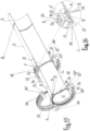
- the tubular element 1 has, at a first end 2, with an enlarged cup-shape (female) equipped with a specially shaped flange 3 so as to create a concentric edge 4 external to the tubular element and respective cavity 41 turned towards the inside of said tubular element 1, suitable for receiving and retaining inside it an elastomeric gasket 11 with a circular seal or of other convenient shape.
- Said tubular element 1, in said end 2, comprises a radial groove 5 which is also concentric, flanked and external to said edge 4, provided with an end edge 6, protruding with respect to the external surface of the tubular element 1.
- a second end 7 (male) of the tubular element 1 is, on the other hand, of the same diameter as the tubular element and is equipped with a preferably continuous radial protuberance with a hump 8.
- the tubes are then assembled by inserting the second male end 7 of a tubular element 1 inside the first cup end 2 of another tubular element 1' up to the end of its axial stroke and, therefore, up to contact of a base or shoulder 9 of the cup-shaped end 2 with the edge of the second end 7, after this edge has passed the elastomeric seal 11 received in the cavity 41.
- said protuberance 8 of the tubular element 1 finds a nest in the end edge 6 of the tubular element 1'.
- a junction block 10 is provided consisting of two semicircles 27, 27' which are placed radially around the tubular element 1, 1' at said concentric edge 4 and at said end edge 6 thus clamping the two tubular elements 1, 1'.
- Said junction block comprises, at its ends, a pair of symmetrical protuberances 31, 31', 32, 32' with through holes 12, 12' capable of accommodating tightening elements such as screws 13 which are locked with relative nuts 14.
- the two semicircles 27, 27', on the inside, have radial cavities 15, 16 specially shaped so as to accommodate inside them the external edge 4 of the flange 3 in the cavity 15 and the end edge 6 of the said flange 3 in the cavity 16.
- the edge of the junction block 10 next to the cavity 16 ( Figure 5 ) has an inclined wall 17 which rests on and covers the protuberance 8 of the tubular element 1 and is equipped with a tooth 18 which, in turn, rests on the outer edge of the tubular element 1.
- the two semicircles 27, 27' therefore geometrically copy the profile of the flange 3 of the tubular element 1', the protuberance 8 and the adjacent part of the tubular element 1, thus creating a solid seaming bond when the tightening screws 13 of the junction block 10 are are screwed in.
- a spacer 28 is provided (optional), specially shaped so as to partially accommodate the protuberances 31, 31', 32, 32' which must be joined together, thus acting as a fixing guide.
- Said spacer 28 is equipped with a bushing 29, able to fit into special holes 30, 30' made in the protuberances 31, 31', 32, 32' as well as a through hole 33 to accommodate the tightening bolts 13.
- the particular geometry of the tooth 20 is such as to ensure the retention of the tubular element as it penetrates to an extent that varies from 0.5 to 1 or more millimetres in the tubular element 1, in relation to its thickness. The penetration must, however, be limited in order not to cause an excessive notch in the wall of the tubular element.
- the crimping ring 19 is provided, in the internal part, with two or more teeth 22, 22' or by a series of two or more teeth 23, 23' parallel to each other and interspersed with free spaces so as to guarantee an even greater pressure seal.
- the junction block 10 is composed of two locking semicircles 27, 27' joined together, on one side, by a connecting pin 34 while, on the other side, the ends are free and can be joined by means of a fixing screw 13 with relative nut 14. In this case, should one wish to use the spacer 28, it is therefore possible to use only one.
- the assembly of a pipe consisting of two or more tubular elements takes place simply by inserting one tubular element inside the other: the male part 7 of a tubular element is introduced into the socket 2 (female part) of the opposite tubular element up to end of the axial stroke in order to guarantee the overcoming of the elastomeric gasket 11 present inside it. It is therefore possible to create a network of pipes in a short time and with the help of a few simple tools.
Landscapes
- Engineering & Computer Science (AREA)
- General Engineering & Computer Science (AREA)
- Mechanical Engineering (AREA)
- Quick-Acting Or Multi-Walled Pipe Joints (AREA)
- Joints With Pressure Members (AREA)
- Branch Pipes, Bends, And The Like (AREA)
- Joints Allowing Movement (AREA)
- Joints With Sleeves (AREA)
Priority Applications (3)
| Application Number | Priority Date | Filing Date | Title |
|---|---|---|---|
| MA59707A MA59707B1 (fr) | 2020-05-05 | 2021-04-30 | Système de raccordement intégré dans des éléments de distribution de fluide tubulaires |
| HRP20241600TT HRP20241600T1 (hr) | 2020-05-05 | 2021-04-30 | Integrirani sustav spajanja u cjevnim elementima za distribuciju tekućine |
| RS20241421A RS66316B1 (sr) | 2020-05-05 | 2021-04-30 | Integrisani sistem za spajanje kod cevastih elemenata za distribuciju fluida |
Applications Claiming Priority (2)
| Application Number | Priority Date | Filing Date | Title |
|---|---|---|---|
| IT102020000009817A IT202000009817A1 (it) | 2020-05-05 | 2020-05-05 | Sistema di giunzione integrato per elementi tubolari di distribuzione dei fluidi |
| PCT/EP2021/025166 WO2021223913A1 (en) | 2020-05-05 | 2021-04-30 | Integrated joining system in tubular fluid distribution elements |
Publications (3)
| Publication Number | Publication Date |
|---|---|
| EP4146972A1 EP4146972A1 (en) | 2023-03-15 |
| EP4146972C0 EP4146972C0 (en) | 2024-10-02 |
| EP4146972B1 true EP4146972B1 (en) | 2024-10-02 |
Family
ID=71662257
Family Applications (1)
| Application Number | Title | Priority Date | Filing Date |
|---|---|---|---|
| EP21723950.8A Active EP4146972B1 (en) | 2020-05-05 | 2021-04-30 | Integrated joining system in tubular fluid distribution elements |
Country Status (16)
| Country | Link |
|---|---|
| US (1) | US12018778B2 (pl) |
| EP (1) | EP4146972B1 (pl) |
| CN (1) | CN115552163B (pl) |
| AU (1) | AU2021267606A1 (pl) |
| BR (1) | BR112022022394A2 (pl) |
| CO (1) | CO2022017234A2 (pl) |
| ES (1) | ES2998688T3 (pl) |
| HR (1) | HRP20241600T1 (pl) |
| HU (1) | HUE069429T2 (pl) |
| IT (1) | IT202000009817A1 (pl) |
| MA (1) | MA59707B1 (pl) |
| MX (1) | MX2022013875A (pl) |
| PL (1) | PL4146972T3 (pl) |
| RS (1) | RS66316B1 (pl) |
| WO (1) | WO2021223913A1 (pl) |
| ZA (1) | ZA202212287B (pl) |
Families Citing this family (3)
| Publication number | Priority date | Publication date | Assignee | Title |
|---|---|---|---|---|
| CN113757461A (zh) * | 2021-02-07 | 2021-12-07 | 上海威逊机械连接件有限公司 | 快装接头 |
| USD1036249S1 (en) * | 2022-03-01 | 2024-07-23 | Bizlink Industry Germany Gmbh | Fastening ring |
| CN114688364B (zh) * | 2022-04-25 | 2024-06-25 | 龚子强 | 一种用于水利工程建设管理的水利管道支撑连接结构 |
Family Cites Families (26)
| Publication number | Priority date | Publication date | Assignee | Title |
|---|---|---|---|---|
| US3485515A (en) * | 1968-01-30 | 1969-12-23 | Mcdowell Mfg Co | Dragline coupling |
| US3964773A (en) * | 1974-09-13 | 1976-06-22 | Mercury Metal Products, Inc. | Anti-emission exhaust pipe joint and clamp therefor |
| US4070046A (en) * | 1976-11-01 | 1978-01-24 | Coupling Systems, Inc. | Pipe and tubing connecting sleeve |
| US4569542A (en) * | 1983-09-26 | 1986-02-11 | Dresser Industries, Inc. | Pipe coupling |
| DE29519221U1 (de) * | 1995-12-05 | 1996-01-25 | Rehau Ag + Co, 95111 Rehau | Längskraftschlüssiges Verbindungselement |
| DE10132631A1 (de) * | 2001-07-05 | 2003-01-23 | Rasmussen Gmbh | Profilschelle und Muffenverbindung mit einer solchen Profilschelle |
| GB2379252A (en) * | 2001-07-18 | 2003-03-05 | Saint Gobain Pipelines Plc | A pipe coupling or flange adapter. |
| CN2500889Y (zh) * | 2001-09-26 | 2002-07-17 | 周锡明 | 管接头 |
| US20040075276A1 (en) * | 2002-04-03 | 2004-04-22 | Cleaire Advanced Emission Controls | Clamped pipe joint, method, and pipe useful therefor |
| FR2863030B1 (fr) * | 2003-11-28 | 2006-01-13 | Vallourec Mannesmann Oil & Gas | Realisation, par expansion plastique, d'un joint tubulaire etanche avec surface(s) de butee inclinee(s) |
| DE502006007750D1 (de) * | 2006-01-05 | 2010-10-07 | Norma Germany Gmbh | Verbindungsanordnung mit Rohrstutzen zum Verbinden von Fluidaufnahmeteilen |
| FR2896572B1 (fr) * | 2006-01-23 | 2009-07-03 | Saint Gobain Pam Sa | Jonction tubulaire |
| US20080054636A1 (en) * | 2006-09-01 | 2008-03-06 | Banjo Corporation | Method and apparatus for coupling a removable fluid conduit to an existing fluid conduit |
| AT505646B1 (de) * | 2007-07-20 | 2010-01-15 | E Hawle Armaturenwerke Gmbh | Rohrverbindung mit einem gehäuse einer armatur |
| KR100833815B1 (ko) * | 2007-12-18 | 2008-06-02 | 신우산업주식회사 | 수밀 및 이탈방지 구조를 갖는 관 |
| US8579334B2 (en) * | 2008-08-06 | 2013-11-12 | Jain Irrigation Systems Limited | Pipe with integral male and female ends, a joint made using the same pipe, and processes of making the pipe and the joint |
| US8596589B2 (en) * | 2009-06-09 | 2013-12-03 | Syntiro Dynamics Llc | Attachable grommets for hanging pipes |
| US20100327579A1 (en) * | 2009-06-25 | 2010-12-30 | John Mezzalingua Associates, Inc. | Fluid fitting |
| US20120299293A1 (en) * | 2011-05-26 | 2012-11-29 | Avi Chiproot | Assembly with separately tightenable annular clamps |
| SG2014009591A (en) * | 2011-09-02 | 2014-09-26 | Victaulic Co Of America | Spin forming method |
| CA2794914C (en) * | 2011-11-08 | 2019-10-15 | Larry Liao | Pipe coupling and method of forming the same |
| CN202937911U (zh) * | 2012-11-01 | 2013-05-15 | 卫德义 | 高压快速管接头 |
| JP6422843B2 (ja) * | 2015-10-27 | 2018-11-14 | 日新製鋼株式会社 | 管状構造物及びその製造方法 |
| US10975992B1 (en) * | 2017-07-01 | 2021-04-13 | Principle CNC Mfg, Inc. | Liquid manure hose coupler |
| US10900597B2 (en) * | 2017-11-29 | 2021-01-26 | Krausz Industries Ltd. | Anti-corrosion pipe system with adjustable length |
| CA3072832A1 (en) * | 2019-02-19 | 2020-08-19 | Duravent, Inc. | Conduit locking system for an appliance |
-
2020
- 2020-05-05 IT IT102020000009817A patent/IT202000009817A1/it unknown
-
2021
- 2021-04-30 CN CN202180033292.7A patent/CN115552163B/zh active Active
- 2021-04-30 RS RS20241421A patent/RS66316B1/sr unknown
- 2021-04-30 PL PL21723950.8T patent/PL4146972T3/pl unknown
- 2021-04-30 US US17/922,936 patent/US12018778B2/en active Active
- 2021-04-30 ES ES21723950T patent/ES2998688T3/es active Active
- 2021-04-30 BR BR112022022394A patent/BR112022022394A2/pt unknown
- 2021-04-30 AU AU2021267606A patent/AU2021267606A1/en active Pending
- 2021-04-30 HU HUE21723950A patent/HUE069429T2/hu unknown
- 2021-04-30 MA MA59707A patent/MA59707B1/fr unknown
- 2021-04-30 EP EP21723950.8A patent/EP4146972B1/en active Active
- 2021-04-30 MX MX2022013875A patent/MX2022013875A/es unknown
- 2021-04-30 WO PCT/EP2021/025166 patent/WO2021223913A1/en not_active Ceased
- 2021-04-30 HR HRP20241600TT patent/HRP20241600T1/hr unknown
-
2022
- 2022-11-10 ZA ZA2022/12287A patent/ZA202212287B/en unknown
- 2022-11-30 CO CONC2022/0017234A patent/CO2022017234A2/es unknown
Also Published As
| Publication number | Publication date |
|---|---|
| BR112022022394A2 (pt) | 2022-12-13 |
| MA59707B1 (fr) | 2024-12-31 |
| HUE069429T2 (hu) | 2025-03-28 |
| WO2021223913A1 (en) | 2021-11-11 |
| PL4146972T3 (pl) | 2025-02-10 |
| RS66316B1 (sr) | 2025-01-31 |
| CN115552163A (zh) | 2022-12-30 |
| IT202000009817A1 (it) | 2021-11-05 |
| CA3182513A1 (en) | 2021-11-11 |
| US12018778B2 (en) | 2024-06-25 |
| AU2021267606A1 (en) | 2022-12-08 |
| HRP20241600T1 (hr) | 2025-01-31 |
| CN115552163B (zh) | 2025-10-24 |
| ZA202212287B (en) | 2023-11-29 |
| US20230160504A1 (en) | 2023-05-25 |
| ES2998688T3 (en) | 2025-02-21 |
| EP4146972C0 (en) | 2024-10-02 |
| MX2022013875A (es) | 2022-11-30 |
| CO2022017234A2 (es) | 2022-12-20 |
| EP4146972A1 (en) | 2023-03-15 |
Similar Documents
| Publication | Publication Date | Title |
|---|---|---|
| EP4146972B1 (en) | Integrated joining system in tubular fluid distribution elements | |
| EP2470817B1 (en) | Press-connect fitting with improved grab-ring function | |
| CA2358120C (en) | Pipe coupling | |
| CA2432266C (en) | Restrained sleeve pipe coupling | |
| US4586734A (en) | Pipe joint assembly | |
| US4930816A (en) | Joining structures for metal pipes | |
| CA2563798A1 (en) | Conduit fitting with pull-up indication | |
| EP0763688A1 (en) | Pipe joint | |
| AU553374B2 (en) | Unitary clamp action fitting | |
| WO2012116183A1 (en) | Pipe coupling assembly with sleeve locking tabs and associated methods | |
| WO2000001973A1 (en) | Pipe coupling | |
| WO2000034704A2 (en) | A jointing system for pipes | |
| CZ294529B6 (cs) | Potrubní spojka | |
| US20020145284A1 (en) | Fitting assembly for corrugated tubing | |
| CA3182513C (en) | Integrated joining system in tubular fluid distribution elements | |
| WO1996012910A1 (en) | Clamp for line fitting | |
| US20240344642A1 (en) | Compression fitting | |
| JP4981783B2 (ja) | 管継手構造用の流体管 | |
| CN111981227A (zh) | 一种大口径管道齿条快装接头 | |
| AU710658B2 (en) | Device for coupling and flaring a metal pipe | |
| JPH11108267A (ja) | 管継手 | |
| KR200296078Y1 (ko) | 배수관용 파이프 연결구 | |
| CA2165646C (en) | Device for coupling and flaring a metal pipe | |
| IE991023A1 (en) | A jointing system | |
| HK1113191A1 (zh) | 管接头 |
Legal Events
| Date | Code | Title | Description |
|---|---|---|---|
| REG | Reference to a national code |
Ref country code: HR Ref legal event code: TUEP Ref document number: P20241600T Country of ref document: HR |
|
| STAA | Information on the status of an ep patent application or granted ep patent |
Free format text: STATUS: UNKNOWN |
|
| STAA | Information on the status of an ep patent application or granted ep patent |
Free format text: STATUS: THE INTERNATIONAL PUBLICATION HAS BEEN MADE |
|
| PUAI | Public reference made under article 153(3) epc to a published international application that has entered the european phase |
Free format text: ORIGINAL CODE: 0009012 |
|
| STAA | Information on the status of an ep patent application or granted ep patent |
Free format text: STATUS: REQUEST FOR EXAMINATION WAS MADE |
|
| 17P | Request for examination filed |
Effective date: 20221128 |
|
| AK | Designated contracting states |
Kind code of ref document: A1 Designated state(s): AL AT BE BG CH CY CZ DE DK EE ES FI FR GB GR HR HU IE IS IT LI LT LU LV MC MK MT NL NO PL PT RO RS SE SI SK SM TR |
|
| P01 | Opt-out of the competence of the unified patent court (upc) registered |
Effective date: 20230524 |
|
| DAX | Request for extension of the european patent (deleted) | ||
| RAV | Requested validation state of the european patent: fee paid |
Extension state: TN Effective date: 20221128 Extension state: MA Effective date: 20221128 |
|
| GRAP | Despatch of communication of intention to grant a patent |
Free format text: ORIGINAL CODE: EPIDOSNIGR1 |
|
| STAA | Information on the status of an ep patent application or granted ep patent |
Free format text: STATUS: GRANT OF PATENT IS INTENDED |
|
| INTG | Intention to grant announced |
Effective date: 20240516 |
|
| GRAS | Grant fee paid |
Free format text: ORIGINAL CODE: EPIDOSNIGR3 |
|
| GRAA | (expected) grant |
Free format text: ORIGINAL CODE: 0009210 |
|
| STAA | Information on the status of an ep patent application or granted ep patent |
Free format text: STATUS: THE PATENT HAS BEEN GRANTED |
|
| AK | Designated contracting states |
Kind code of ref document: B1 Designated state(s): AL AT BE BG CH CY CZ DE DK EE ES FI FR GB GR HR HU IE IS IT LI LT LU LV MC MK MT NL NO PL PT RO RS SE SI SK SM TR |
|
| REG | Reference to a national code |
Ref country code: GB Ref legal event code: FG4D |
|
| REG | Reference to a national code |
Ref country code: CH Ref legal event code: EP |
|
| REG | Reference to a national code |
Ref country code: DE Ref legal event code: R096 Ref document number: 602021019595 Country of ref document: DE |
|
| REG | Reference to a national code |
Ref country code: IE Ref legal event code: FG4D |
|
| U01 | Request for unitary effect filed |
Effective date: 20241017 |
|
| P04 | Withdrawal of opt-out of the competence of the unified patent court (upc) registered |
Free format text: CASE NUMBER: APP_59069/2024 Effective date: 20241030 |
|
| U07 | Unitary effect registered |
Designated state(s): AT BE BG DE DK EE FI FR IT LT LU LV MT NL PT RO SE SI Effective date: 20241104 |
|
| REG | Reference to a national code |
Ref country code: MA Ref legal event code: VAGR Ref document number: 59707 Country of ref document: MA Kind code of ref document: B1 |
|
| REG | Reference to a national code |
Ref country code: GR Ref legal event code: EP Ref document number: 20240402912 Country of ref document: GR Effective date: 20250120 |
|
| REG | Reference to a national code |
Ref country code: HR Ref legal event code: T1PR Ref document number: P20241600 Country of ref document: HR |
|
| REG | Reference to a national code |
Ref country code: SK Ref legal event code: T3 Ref document number: E 45592 Country of ref document: SK |
|
| REG | Reference to a national code |
Ref country code: ES Ref legal event code: FG2A Ref document number: 2998688 Country of ref document: ES Kind code of ref document: T3 Effective date: 20250221 |
|
| REG | Reference to a national code |
Ref country code: HU Ref legal event code: AG4A Ref document number: E069429 Country of ref document: HU |
|
| PG25 | Lapsed in a contracting state [announced via postgrant information from national office to epo] |
Ref country code: IS Free format text: LAPSE BECAUSE OF FAILURE TO SUBMIT A TRANSLATION OF THE DESCRIPTION OR TO PAY THE FEE WITHIN THE PRESCRIBED TIME-LIMIT Effective date: 20250202 |
|
| PGFP | Annual fee paid to national office [announced via postgrant information from national office to epo] |
Ref country code: NO Payment date: 20250321 Year of fee payment: 5 |
|
| PGFP | Annual fee paid to national office [announced via postgrant information from national office to epo] |
Ref country code: GB Payment date: 20250321 Year of fee payment: 5 |
|
| PGFP | Annual fee paid to national office [announced via postgrant information from national office to epo] |
Ref country code: TR Payment date: 20250329 Year of fee payment: 5 |
|
| U20 | Renewal fee for the european patent with unitary effect paid |
Year of fee payment: 5 Effective date: 20250321 |
|
| REG | Reference to a national code |
Ref country code: HR Ref legal event code: ODRP Ref document number: P20241600 Country of ref document: HR Payment date: 20250404 Year of fee payment: 5 |
|
| PGFP | Annual fee paid to national office [announced via postgrant information from national office to epo] |
Ref country code: AL Payment date: 20250320 Year of fee payment: 5 |
|
| PG25 | Lapsed in a contracting state [announced via postgrant information from national office to epo] |
Ref country code: SM Free format text: LAPSE BECAUSE OF FAILURE TO SUBMIT A TRANSLATION OF THE DESCRIPTION OR TO PAY THE FEE WITHIN THE PRESCRIBED TIME-LIMIT Effective date: 20241002 |
|
| PGFP | Annual fee paid to national office [announced via postgrant information from national office to epo] |
Ref country code: PL Payment date: 20250403 Year of fee payment: 5 |
|
| PGFP | Annual fee paid to national office [announced via postgrant information from national office to epo] |
Ref country code: ES Payment date: 20250505 Year of fee payment: 5 |
|
| PGFP | Annual fee paid to national office [announced via postgrant information from national office to epo] |
Ref country code: HU Payment date: 20250409 Year of fee payment: 5 Ref country code: RS Payment date: 20250403 Year of fee payment: 5 |
|
| PGFP | Annual fee paid to national office [announced via postgrant information from national office to epo] |
Ref country code: HR Payment date: 20250404 Year of fee payment: 5 |
|
| PGFP | Annual fee paid to national office [announced via postgrant information from national office to epo] |
Ref country code: GR Payment date: 20250407 Year of fee payment: 5 |
|
| PGFP | Annual fee paid to national office [announced via postgrant information from national office to epo] |
Ref country code: CH Payment date: 20250501 Year of fee payment: 5 |
|
| PGFP | Annual fee paid to national office [announced via postgrant information from national office to epo] |
Ref country code: SK Payment date: 20250407 Year of fee payment: 5 |
|
| PGFP | Annual fee paid to national office [announced via postgrant information from national office to epo] |
Ref country code: CZ Payment date: 20250408 Year of fee payment: 5 |
|
| PGFP | Annual fee paid to national office [announced via postgrant information from national office to epo] |
Ref country code: IE Payment date: 20250403 Year of fee payment: 5 |
|
| PLBE | No opposition filed within time limit |
Free format text: ORIGINAL CODE: 0009261 |
|
| STAA | Information on the status of an ep patent application or granted ep patent |
Free format text: STATUS: NO OPPOSITION FILED WITHIN TIME LIMIT |
|
| 26N | No opposition filed |
Effective date: 20250703 |
|
| PGFP | Annual fee paid to national office [announced via postgrant information from national office to epo] |
Ref country code: MK Payment date: 20250403 Year of fee payment: 5 |
|
| VSFP | Annual fee paid to validation state [announced via postgrant information from national office to epo] |
Ref country code: MA Payment date: 20250416 Year of fee payment: 5 |
|
| PG25 | Lapsed in a contracting state [announced via postgrant information from national office to epo] |
Ref country code: MC Free format text: LAPSE BECAUSE OF FAILURE TO SUBMIT A TRANSLATION OF THE DESCRIPTION OR TO PAY THE FEE WITHIN THE PRESCRIBED TIME-LIMIT Effective date: 20241002 |
|
| PGFP | Annual fee paid to national office [announced via postgrant information from national office to epo] |
Ref country code: CY Payment date: 20250407 Year of fee payment: 5 |