EP4145960A1 - System zur steuerung einer adaptiven beleuchtungsanlage und entsprechendes verfahren - Google Patents
System zur steuerung einer adaptiven beleuchtungsanlage und entsprechendes verfahren Download PDFInfo
- Publication number
- EP4145960A1 EP4145960A1 EP22193530.7A EP22193530A EP4145960A1 EP 4145960 A1 EP4145960 A1 EP 4145960A1 EP 22193530 A EP22193530 A EP 22193530A EP 4145960 A1 EP4145960 A1 EP 4145960A1
- Authority
- EP
- European Patent Office
- Prior art keywords
- lighting
- luminance
- traffic lane
- tables
- installation
- Prior art date
- Legal status (The legal status is an assumption and is not a legal conclusion. Google has not performed a legal analysis and makes no representation as to the accuracy of the status listed.)
- Granted
Links
Images


Classifications
-
- H—ELECTRICITY
- H05—ELECTRIC TECHNIQUES NOT OTHERWISE PROVIDED FOR
- H05B—ELECTRIC HEATING; ELECTRIC LIGHT SOURCES NOT OTHERWISE PROVIDED FOR; CIRCUIT ARRANGEMENTS FOR ELECTRIC LIGHT SOURCES, IN GENERAL
- H05B45/00—Circuit arrangements for operating light-emitting diodes [LED]
- H05B45/10—Controlling the intensity of the light
- H05B45/12—Controlling the intensity of the light using optical feedback
-
- H—ELECTRICITY
- H05—ELECTRIC TECHNIQUES NOT OTHERWISE PROVIDED FOR
- H05B—ELECTRIC HEATING; ELECTRIC LIGHT SOURCES NOT OTHERWISE PROVIDED FOR; CIRCUIT ARRANGEMENTS FOR ELECTRIC LIGHT SOURCES, IN GENERAL
- H05B47/00—Circuit arrangements for operating light sources in general, i.e. where the type of light source is not relevant
- H05B47/10—Controlling the light source
- H05B47/175—Controlling the light source by remote control
- H05B47/198—Grouping of control procedures or address assignation to light sources
-
- G—PHYSICS
- G06—COMPUTING OR CALCULATING; COUNTING
- G06V—IMAGE OR VIDEO RECOGNITION OR UNDERSTANDING
- G06V10/00—Arrangements for image or video recognition or understanding
- G06V10/10—Image acquisition
- G06V10/12—Details of acquisition arrangements; Constructional details thereof
- G06V10/14—Optical characteristics of the device performing the acquisition or on the illumination arrangements
- G06V10/141—Control of illumination
-
- G—PHYSICS
- G06—COMPUTING OR CALCULATING; COUNTING
- G06V—IMAGE OR VIDEO RECOGNITION OR UNDERSTANDING
- G06V20/00—Scenes; Scene-specific elements
- G06V20/50—Context or environment of the image
- G06V20/52—Surveillance or monitoring of activities, e.g. for recognising suspicious objects
- G06V20/54—Surveillance or monitoring of activities, e.g. for recognising suspicious objects of traffic, e.g. cars on the road, trains or boats
-
- H—ELECTRICITY
- H05—ELECTRIC TECHNIQUES NOT OTHERWISE PROVIDED FOR
- H05B—ELECTRIC HEATING; ELECTRIC LIGHT SOURCES NOT OTHERWISE PROVIDED FOR; CIRCUIT ARRANGEMENTS FOR ELECTRIC LIGHT SOURCES, IN GENERAL
- H05B47/00—Circuit arrangements for operating light sources in general, i.e. where the type of light source is not relevant
- H05B47/10—Controlling the light source
- H05B47/105—Controlling the light source in response to determined parameters
- H05B47/11—Controlling the light source in response to determined parameters by determining the brightness or colour temperature of ambient light
-
- H—ELECTRICITY
- H05—ELECTRIC TECHNIQUES NOT OTHERWISE PROVIDED FOR
- H05B—ELECTRIC HEATING; ELECTRIC LIGHT SOURCES NOT OTHERWISE PROVIDED FOR; CIRCUIT ARRANGEMENTS FOR ELECTRIC LIGHT SOURCES, IN GENERAL
- H05B47/00—Circuit arrangements for operating light sources in general, i.e. where the type of light source is not relevant
- H05B47/10—Controlling the light source
- H05B47/175—Controlling the light source by remote control
Definitions
- the present invention generally relates to the management of a lighting installation, in particular for traffic lane lighting luminaires.
- traffic lanes It is desirable for traffic lanes to be properly lit so that users of these lanes, such as pedestrians, cyclists or motorists, can circulate in a safe manner, while limiting light pollution or energy waste.
- the document US2021112647A1 describes a light emitting system which comprises an angular variation light emitting device which allows the luminous flux of the light sources to be individually modified in different angular zones of the environment.
- a light sensor is positioned to receive light from the angle-variable light-emitting device.
- the luminous flux is adjusted reliably and quickly in order to be able to quickly adapt the lighting to the state of the traffic lane, in particular to limit the risk of accidents on the lane which could occur in the case a lighting modification that would be carried out inappropriately or with too long a modification time resulting, for example, from trial and error in the adjustments.
- the aim of the present invention is to propose a new lighting installation management system and a corresponding method making it possible to overcome all or part of the problems set out above.
- the system makes it possible to measure a change in the optical properties of the traffic lane and to control the lighting installation to correct the lighting and thus obtain lighting adapted to reference criteria by taking into account the optical properties of the traffic lane. traffic.
- These reference criteria may correspond to normative requirements.
- the management system thus makes it possible to control the photometric operating characteristics (incident luminosity) of the lighting luminaire(s) according to the optical properties of the material of the traffic lane.
- the optical properties may depend on the surface condition (dry, damp, wet, soaked, as well as new or worn) of the roadway.
- the control module makes it possible, using the optical properties of the traffic lane determined from the information provided by the image acquisition device, to control the luminaires of the lighting installation according to a scenario of lighting adapted to the optical properties of reflection of the traffic lane to obtain the desired luminance characteristics (reference criteria).
- the benchmarks preferably include a minimum average luminance value, a minimum overall uniformity value, and a minimum longitudinal uniformity value.
- the system according to the invention thus makes it possible to optimize the operation of the lighting installation according to the optical reflection properties of the road to be lit.
- the system according to the invention makes it possible to reliably determine optical reflection parameters, preferably at least 580 values of the real r-table of the traffic lane, in order to be able to precisely adjust the intensity distribution light (illumination) to obtain a suitable average luminance and to optimize the general and longitudinal luminance uniformities.
- the system also makes it possible to control the operation of the lighting installation taking into account the type of user, cyclist, pedestrian, motorist, etc. who uses the traffic lane.
- the system may also include one or more of the following features taken in any technically permissible combination.
- Such a combination of operations of analysis into principal components, of generation of virtual luminance maps and of decomposition of the luminance map, makes it possible to obtain suitable coefficients for determining by linear combination of eigenvectors with these coefficients, said set optical reflection characteristics of the taxiway.
- These operations carried out in particular from the physical parameters relating to the luminance map and the photometries, make it possible to quickly and reliably determine the optical characteristics of the track in order to be able to directly adjust the lighting sources of the lighting installation, which saves time and increases precision in order to obtain the appropriate setting and thus limit safety problems, in particular limit the risk of accidents on the track due to inappropriate lighting, which could otherwise be caused by trial and error in the settings.
- the sets of reference optical reflection characteristics being reference r-tables
- the or each lighting source comprises one or more LEDs.
- the lighting installation comprises several luminaires, each luminaire comprising a part of said lighting sources of the lighting installation, each luminaire comprising a device for controlling the power supply of the lighting sources of the light fixture.
- the step of controlling the lighting sources is also carried out according to a type of user who circulates on the traffic lane.
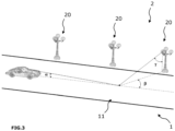
- the lighting installation is arranged to illuminate traffic lane 1.
- the lighting installation management system is adaptive due to the fact that the lighting (number of lighting sources supplied, the supply of the lighting sources, the spatial distribution of the light intensity of the installation) can be adapted according to the characteristics of the object and/or the environment of the object to be illuminated.
- the traffic lane has different optical reflection properties.
- the optical reflection properties comprise values of a reduced luminance coefficient r for different angle values as detailed below. This data is organized in a table, or matrix, called table-r.
- the management system is configured to find the optical reflection characteristics of a traffic lane.
- the management system makes it possible to estimate an r-table, denoted Tr est , of the traffic lane from a luminance image L mes of the zone 11 of the traffic lane 1 whose image has been acquired by an image acquisition device 3 and photometric data of the lighting sources of the lighting installation in use.
- the optical reflection properties of the traffic lane can be described in the form of tables of luminance coefficients q.
- the variations of q as a function of the angle ⁇ are negligible and the angle ⁇ is considered equal to 1 °.
- the angle ⁇ being defined, the luminance coefficient q depends on ⁇ and ⁇ (more particularly tan y).
- ⁇ is sampled between 0° and 180° over 20 points
- tan ⁇ is sampled between 0 and 12 (0° ⁇ y ⁇ 86°) over 29 points.
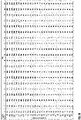
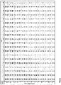
- the r-table can thus be presented in the form of a 29x20 matrix.
- the optical reflection characteristics can also be presented in the form of bidirectional reflection distribution functions (BRDF in English for Bi-directional Reflectance Distribution Function).
- BRDF Bi-directional Reflectance Distribution Function
- An r-table is usually considered part of the bidirectional reflection distribution functions.
- An r-table describes optical reflective properties of a surface, such as a traffic lane, in the form of a matrix.
- the r-table connects the incident light, also usually called horizontal illumination, produced by a lighting source, to the light reflected (the luminance) by the illuminated surface towards the eye of an observer, for example a driver, to a given viewing angle.
- the distribution of the luminous intensity of a light source or a set of light sources i.e. the light intensity emitted according to different directions or angles by the light source or the lighting source assembly for a given power supply (power, voltage and/or intensity), and its location (position in space), which corresponds to a given photometry as detailed below, it is possible to calculate the luminance (reflected light intensity) of the illuminated area of the traffic lane and deduce therefrom lighting quality criteria for the traffic lane related to its clarity (average luminance of the road) and its homogeneity ( general and longitudinal uniformity).
- the International Commission on Illumination has defined Q0 clarity and S1 specularity coefficients to summarize the reflectivity of road surfaces.
- the coefficients of clarity Q0 and specularity S1 are deduced from the measurements of the luminance coefficient.
- a coating reflects light in a pattern where both specular (mirror effect) and diffuse components contribute.
- the average luminance coefficient Q0 describes the clarity of the coating.
- the reference r-tables can be differentiated from each other by these coefficients Q0 and S1.
- the lighting installation 2 comprises several luminaires 20.
- the description also applies to the case where the lighting installation comprises a single luminaire 20.
- the luminaires 20 are arranged to illuminate the traffic lane 1.
- the traffic lane can also be called roadway, road, etc... traffic can also be made up of several traffic lanes.
- traffic lane can be traversed by pedestrians, cyclists and/or drivers of motorized vehicles such as cars.
- Each luminaire 20 comprises a support structure, such as a mast, and lighting sources carried by the mast.
- the lighting sources comprise at least two lighting sources whose electrical power supply is controllable to make it possible to vary the light intensity value emitted from each lighting source (that is to say the incident intensity or lighting).
- each light source is an LED, but the description also applies to other light sources whose power supply is controllable, such as plasma light sources.
- the power supply of the lighting source it is possible to modify the light intensity emitted by the lighting source.
- the luminaire includes a device such as an electronic module for controlling the power supply of the LEDs (also called a driver).
- Lighting sources can be associated with optics, such as lenses for LEDs. Provision may be made for the luminaire to comprise one optic per lighting source or per group of lighting sources.
- Each luminaire 20 is associated with a plurality of photometries.
- a first photometry 201 and a second photometry 202 have been schematized for a given luminaire 20.
- a set of LEDs of a photometry can be considered as a point source.
- said light intensity value is a relative light intensity value in candela per kilo lumen (cd/klm), that is to say the light intensity emitted by the set of LEDs for 1000 lumens.
- the processing unit 100 can comprise a photometry file which gives, for different combinations of angle value denoted C (from 0 to 360°), and of angle values ⁇ (from 0 to 180 °), the light intensity that the LED assembly can emit for 1000 lumen (cd/klm) in the direction corresponding to this combination of angles.
- the angle C (not shown) is the angle made, in projection in a horizontal plane, by the direction of emission (direction of incidence) with a reference axis in said horizontal plane.
- the light intensity emitted by the LED assembly depends on the electrical power (intensity) supplied to it.
- a set of LEDs of a photometry can be configured to emit 100 kilo lumens when said set of LEDs is supplied with maximum operating electrical power. It is then possible to obtain a desired light intensity for a given photometry by adapting the power (voltage and/or intensity) supplied to the assembly of LEDs of the photometry which makes it possible to achieve this desired light intensity.
- each photometry comprises a group of LEDs, but the description also applies to the case where a photometry comprises a single LED or another controllable lighting source whose power supply is controllable.
- the LEDs of one photometry can be powered independently of the LEDs of another photometry of the luminaire. Thus provision can be made to turn off the LEDs of one photometry and to turn on the LEDs of another photometry.
- the first photometry 201 comprises 48 LEDs and the second photometry 202 comprises 48 other LEDs that can be controlled independently of the 48 LEDs of the first photometry.
- the percentage can be applied to the number of lit photometry LEDs.
- Different combinations of driving LEDs of different photometries can also be implemented.
- the positioning geometry of the luminaires and the lighting sources of the installation with respect to the traffic lane is known to the management system.
- Corresponding position data can thus be stored in a memory of a processing unit 100 presented below.
- the management system knows the position in space with respect to the traffic lane 1 of the lighting source assemblies of the photometries of the luminaires.
- each luminaire comprises a module (or device) for controlling the lighting LEDs that the luminaire embeds.
- the control module is used to control the LED power supply (power, voltage and/or intensity).
- the control module is used to control a power supply different for each LED or group of LEDs in order to be able to adjust the intensity of the luminous flux of the luminaire and preferably the spatial distribution (and therefore the homogeneity or uniformity) of the luminous flux of the luminaire.
- LEDs as lighting sources for the luminaires makes it possible to effectively modulate the lighting, both in quantity (total outgoing flux) and in spatial distribution on the traffic lane (uniformities).
- the LED luminaire or luminaires can be associated with sensors, such as user detection sensors so that the management system can be configured to control the lighting source of the or each luminaire according to the data provided by one or more sensors.
- the management system comprises an image acquisition device 3.
- the image acquisition device 3 makes it possible to acquire an image of the zone 11 of the traffic lane 1 and to generate a corresponding image in luminance L mes (cd/m2).
- the image acquisition device 3 is previously calibrated in luminance on an optical bench in the laboratory to provide, for one or different settings of the image acquisition device 3, the correspondence between the different level values of gray that the points of an acquired image can take and the luminance values.
- Calibration is done by determining the parameters of an equation that relates gray level values to luminance values.
- the points of the image correspond to the area of the road whose image has been acquired and the luminance image corresponds to all the luminance values (reflected light intensity) associated with the various points.
- the graduation of the abscissa axis and the graduation of the ordinate axis correspond to coordinates of the points (luminance measurement points) of the imaged zone of the imaged traffic lane.
- the color scale to the right of the image indicates a luminance level (candela/m2).
- the image acquisition device can thus provide luminance images, also called measured luminance maps.
- luminance images also called measured luminance maps.
- the luminance of the traffic lane illuminated by the luminaires 20 of the lighting installation 2 is measured continuously.
- the luminance map L mes obtained is then analyzed as a function of the photometric data and the position of each luminaire 20 to determine an r-table of the zone 11 of the traffic lane 1 illuminated by the installation lighting.
- the management system includes a processing unit 100.
- the processing unit 100 includes a memory in which are stored photometry data for each luminaire.
- the processing unit 100 also includes a module 4 for determining optical reflection characteristics.
- the module 4 for determining optical reflection characteristics is an r-table determination module which makes it possible to construct (generate) an r-table representative of the optical properties of a zone 11 of the track. traffic light 1 illuminated by the lighting installation, as explained below.
- the table-r determination module 4 is configured to determine, preferably in real time, the table-r of the zone 11 of the traffic lane, and this according to the photometry data during use of the luminaires, and of the image in luminance L mes measured.
- the processing unit 100 also includes a control module 6 configured to transmit instructions to the luminaires of the lighting installation to control associated sets of lighting sources.
- the processing unit 100 and in particular the r-table determination module 4 presented below has access to the photometry data with which the luminaires 20 are operating.
- the photometry data with which each luminaire is in operation can be determined from the instructions of the control module 6 transmitted to the luminaires.
- the processing unit 100 comprises a base of r-tables, called virtual r-tables, which are formed from reference r-tables, already known, by applying to these reference r-tables a principal component analysis as explained below.
- the reference r-tables can be chosen from reference r-tables defined by the CIE.
- CIE Commission Internationale de L'Eclairage
- a person skilled in the art has access to reference tables, for example in the publication "CIE 144:2001 Road surface and road marking reflection characteristics standard by Commission Internationale de L'Eclairage, 01/01/2001” , such as the reference tables usually denoted C1, C2, R1..R4, N1..N4, W1..W4.
- provision may be made to take experimentally measured tables as the reference table.
- the reference r-tables comprise 14 r-tables, defined by the CIE and provided to Figures 5A-5N .
- the reference r-tables 1010 may include previously measured tables actually or resulting from an average of measured tables.
- the reference r-tables used to form the virtual r-tables can also comprise experimental r-tables, for example measured with a gonioreflectometer.
- the reference r-tables present different values of clarity coefficient Q0 and of specularity coefficient S1.
- the r-table generation module 4 is configured to apply a principal component analysis (PCA) to a plurality of reference r-tables 1010.
- PCA principal component analysis
- reference tables 1010 The principal component analysis of these reference tables 1010 makes it possible to obtain virtual tables 1020, also called eigenvectors r v1 , r v2 ,..., r vD .
- virtual tables 1020 also called eigenvectors r v1 , r v2 ,..., r vD .
- PCA is a dimensionality reduction method that can be used to reduce the dimensionality of large datasets, by transforming a large set of variables into a smaller one that still contains the majority of the information in the large set.
- the mean of each variable (or parameter) is subtracted from said variable, so that each of the variables contributes equally to the analysis.
- a covariance matrix is calculated to identify correlations.
- the eigenvectors and eigenvalues of the covariance matrix are calculated using a singular value decomposition (SVD) algorithm to identify the principal components.
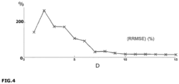
- the objective is to reduce the dimensionality 580 (corresponding to the dimension 29x20 of each r-table) in order to more easily solve a linear system containing a number of equations corresponding to the number of points NG of the luminance image.
- An RRMSE value is obtained for each reference r-table and for each dimensionality of the space.
- the median of the RRMSE error is plotted as shown for example in Figure 4 .
- D is an integer greater than 0.
- the lighting source intensity I and the associated angle ⁇ come from the photometry data with which the luminaires of the installation are in operation.
- Equation (IV) can thus be applied, for each virtual r-table (to which the terms r i,p correspond), to the lighting configuration of the lighting installation during operation, ie by using , for each point P of the zone of the traffic lane whose image is acquired, values of intensity of lighting source I and of associated angle ⁇ , for N S lighting sources, resulting from photometry or the combination of photometry with which the lighting installation is in operation.
- the set of points P forms a map or grids of N G points.
- N G is for example equal to 60.
- Said points P are surface points of zone 11 of the taxiway whose image is acquired.
- the D virtual r-tables make it possible to obtain D luminance maps L v1 , L v2 , ..., L vD , called virtual luminance maps (or also called proper maps), which thus form a base of maps of virtual luminance as shown in Figure 2 .
- the set of luminance maps is denoted 1030 at the Figure 2 .
- a virtual luminance map is thus presented in the form of a matrix of the same size as the measured luminance map but whose values have no physical meaning (and may be negative).
- each proper luminance map is associated with a principal component of the virtual r-table database and serves as a basis for decomposing a measured luminance map.
- the r-table determination module 4 breaks down the measured luminance map L mes (to which correspond points P of luminance value L p_mes ), on the generated virtual luminance maps L v1 , L v2 ,..., L vD , so as to obtain coefficients ⁇ 1 , ⁇ 2 ...
- ⁇ D associated with the generated virtual luminance maps L v1 , L v2 ,..., L vD which correspond to the following system of equations (V) defined for the points P of the image:
- I p _ my ⁇ 1 , I p _ v1 + ⁇ 2 I p _ v 2 ... + ⁇ D I p _ vD with L p_vi the luminance of point P of virtual luminance map n° i, and i ranging from 1 to D.
- the system of equations can be solved by the method of least squares. This method determines the best linear combination of the generated virtual luminance maps L v1 , L v2 , ..., L vD to best approximate the measured luminance map L mes and provide the corresponding coefficients ⁇ 1 , ⁇ 2 ... ⁇ D
- the method makes it possible to determine the optical reflective properties of the traffic lane using the luminaires, without the need to install specific additional luminaires.
- the estimated r-table Tr is thus generated and is used by the control module 6 of the lighting installation 2 to generate instructions C62 for the luminaires 20, as a function of reference luminance characteristics 21 desired for the zone 11 of the traffic lane 1, in order to obtain an appropriate adjustment of the light sources for each luminaire.
- the control module 6 makes it possible to control the luminaires, using the data from the r-table Tr is determined and from the measured luminance map L mes , to obtain luminance characteristics, which preferably include a luminance value mean and uniformity values (longitudinal and general), which come as close as possible to reference luminance characteristics, which result for example from normative requirements.
- the reference (or desired) luminance characteristics may depend on the type of channel (also called class).
- an average luminance value of zone 11 at least equal to a value I minimum given, and with a homogeneity (homogeneity) of the luminance values associated with the points P zone 11: it is desirable to obtain the most homogeneous (uniform) distribution of the luminance values on the points P zone 11.
- Homogeneity includes a general uniformity criterion U 0 and a longitudinal uniformity criterion U l .
- the overall uniformity is given as the ratio of the minimum luminance among the luminance values at the P points to the average luminance of the luminance values at the P points.
- the longitudinal uniformity is given as the ratio of the minimum luminance to the maximum luminance among the luminance values of the points P located in the middle of the traffic lane.
- reference luminance characteristics are given below for different classes (or types) of traffic lanes. These reference luminance characteristics correspond to the minimum average luminance values I , general uniformity U 0 and longitudinal uniformity U l to be achieved for different classes M1 - M6 corresponding to different types of track.
- Class I [minimum maintained] cd m 2 U o [minimum] U l [minimum] M1 2.00 0.40 0.70 M2 1.50 0.40 0.70 M3 1.00 0.40 0.60 M4 0.75 0.40 0.60 M5 0.50 0.35 0.40 N16 0.30 0.35 0.40
- An M1 type traffic lane is a lane that requires a greater minimum luminance value than an M2... or M6 type lane.
- a lane of M1 type can thus be a motorway, and conversely a lane of M6 type can be a pedestrian lane.
- the processing unit 100 includes in memory reference characteristics corresponding to the type of lane of the traffic lane whose image is acquired. Provision may be made for the processing unit to include several sets of reference characteristics for different types of road, and for an interface to allow an operator to enter the type of road whose image is acquired in order to allow the unit to processing to select the reference characteristics associated with the type of road indicated by the operator.
- the reference characteristics can be predefined in the processing unit taking into account the type of channel for which the processing unit is intended to be used.
- the control module simulates, from the set of available photometries and combinations thereof, and for different power supply values of the LEDs of the photometries, different lighting configurations giving different lighting values E p for each point P of zone 11 of the taxiway.
- the control module 6 calculates, from the calculated E p values, and from the estimated table-r previously generated by the table-r determination module 4, an estimated luminance map L is .
- the control module 6 calculates, for each map of estimated luminance L is , the average luminance value and one or more uniformities of the luminance values on the points P of the zone 11, and identifies the map of estimated luminance L is , for which the average luminance value and the uniformities of the luminance values on the points P of the zone 11 most closely approximate the reference luminance value and the reference uniformity(ies) for taxiway 1.
- the type of channel (M1, M2,... or M6) is stored in the processing unit so that the control module knows the reference characteristics to be used to perform the comparison operation.
- the control module 6 identifies, from said identified estimated luminance map Lest, the photometry or the combination of photometries, with the associated power supply of the LEDs, which made it possible to obtain said identified estimated luminance map Lest.
- the control module 6 then transmits instructions to the luminaires for the activation of said identified photometry, or combination of photometries, with the associated power supply for the LEDs.
- control modules also called “drivers”
- the processing unit can determine the photometry or the combination of photometry of the luminaire or luminaires which is in use as being that resulting from the instructions issued by the control module 6 .
- each luminaire can thus be controlled to tend towards an optimal adjustment taking into account the characteristics of the estimated r-table.
- the lighting provided by each luminaire can thus be adapted to the surface condition of the traffic lane, for example dry or wet.
- the r-table determination module 4 can be made for the r-table determination module 4 to generate the r-table of the zone 11 of the taxiway 1 for different viewing angles of said zone 11.
- the lighting of each luminaire can then also be controlled according to the type of user, in particular pedestrian, cyclist or motorist traveling on the traffic lane by selecting an estimated r-table which has been calculated for a given angle corresponding to the type of user detected. Different r-tables can thus be estimated according to the type of user considered, ie for different observation angles.
- the control module 6 can thus receive as an input parameter, for example provided by a presence sensor, the type of user circulating on the track, with which is associated a given observation angle, for example 1° for a car, and 10° for a pedestrian, and control the lights 20 as a function of the generated r-table whose associated observation angle corresponds to the type of user identified.
- the image acquisition device 3 is positioned relative to the traffic lane 1 so as to offer a given viewing angle corresponding to the viewing angle of a type of user of the traffic lane, for example a car. Provision may be made for the image acquisition device 3 to be movable in order to acquire the image according to another viewing angle corresponding to another type of user. Since an r-table is calculated for a given angle of vision, provision can be made for the image acquisition device to be movable along different orientations to obtain luminance images at different angles and thus to obtain r-tables for different angles.
- the processing unit 100 makes it possible to adapt the lighting scenario implemented (i.e. the instructions) according to the optical reflection properties of the surface of the traffic lane (which may vary over the years and according to the weather conditions ) due to the presence in the luminaires of several distinct photometries, for example one dedicated to a dry coating, the other to a wet coating.
- the control module 6 of the processing unit 100 makes it possible to implement a lighting scenario (that is to say a set of instructions) mobilizing one or other of the photometries as well as a set of linear combinations between them.
- the system may comprise a control cabinet for the lighting installation housing the processing unit 100.
- the processing unit may be housed at the level of a supervisory system or directly in the imaging system, i.e. the image acquisition device, which can then form an intelligent camera.
- the processing unit is for example in the form of a processor and a data memory in which are stored computer instructions executable by said processor, or even in the form of a microcontroller.
- the described functions and steps can be implemented as a computer program or via hardware components (eg programmable gate arrays).
- the functions and steps operated by the processing unit can be performed by sets of instructions or computer modules implemented in a processor or controller or be performed by dedicated electronic components or components of the programmable logic circuit type (or FPGA which is the acronym for field-programmable gate array, which literally corresponds to a network of in-situ programmable gates) or of the type of integrated circuit specific to an application (or ASIC which is the acronym for application-specific integrated circuit, which literally stands for application-specific integrated circuit). It is also possible to combine computer parts and electronic parts.
- the processing unit is thus an electronic and/or computer unit.
- said unit is configured to carry out a given operation, this means that the unit comprises computer instructions and the corresponding means of execution which make it possible to carry out said operation and/or that the unit comprises electronic components correspondents.
Landscapes
- Engineering & Computer Science (AREA)
- Physics & Mathematics (AREA)
- General Physics & Mathematics (AREA)
- Multimedia (AREA)
- Theoretical Computer Science (AREA)
- Circuit Arrangement For Electric Light Sources In General (AREA)
- Traffic Control Systems (AREA)
Applications Claiming Priority (1)
| Application Number | Priority Date | Filing Date | Title |
|---|---|---|---|
| FR2109188A FR3126590B1 (fr) | 2021-09-02 | 2021-09-02 | Système de gestion d’une installation d’éclairage adaptatif et procédé correspondant |
Publications (3)
| Publication Number | Publication Date |
|---|---|
| EP4145960A1 true EP4145960A1 (de) | 2023-03-08 |
| EP4145960B1 EP4145960B1 (de) | 2025-07-30 |
| EP4145960C0 EP4145960C0 (de) | 2025-07-30 |
Family
ID=79831260
Family Applications (1)
| Application Number | Title | Priority Date | Filing Date |
|---|---|---|---|
| EP22193530.7A Active EP4145960B1 (de) | 2021-09-02 | 2022-09-01 | System zur steuerung einer adaptiven beleuchtungsanlage und entsprechendes verfahren |
Country Status (2)
| Country | Link |
|---|---|
| EP (1) | EP4145960B1 (de) |
| FR (1) | FR3126590B1 (de) |
Families Citing this family (1)
| Publication number | Priority date | Publication date | Assignee | Title |
|---|---|---|---|---|
| CN121170468A (zh) * | 2025-09-30 | 2025-12-19 | 武汉大道慧云科技有限公司 | 一种路灯能耗分析方法 |
Citations (2)
| Publication number | Priority date | Publication date | Assignee | Title |
|---|---|---|---|---|
| WO2018046488A1 (en) * | 2016-09-07 | 2018-03-15 | Philips Lighting Holding B.V. | Mapping and auditing luminaires across geographic areas |
| US20210112647A1 (en) | 2018-05-07 | 2021-04-15 | Zane Coleman | Angularly varying light emitting device with an imager |
-
2021
- 2021-09-02 FR FR2109188A patent/FR3126590B1/fr active Active
-
2022
- 2022-09-01 EP EP22193530.7A patent/EP4145960B1/de active Active
Patent Citations (2)
| Publication number | Priority date | Publication date | Assignee | Title |
|---|---|---|---|---|
| WO2018046488A1 (en) * | 2016-09-07 | 2018-03-15 | Philips Lighting Holding B.V. | Mapping and auditing luminaires across geographic areas |
| US20210112647A1 (en) | 2018-05-07 | 2021-04-15 | Zane Coleman | Angularly varying light emitting device with an imager |
Non-Patent Citations (3)
| Title |
|---|
| BOMMEL ET AL.: "Road Surfaces and lighting", JOINT TECHNICAL REPORT CIE/PIARC |
| BOMMEL ET AL: "Road Surfaces and lighting", JOINT TECHNICAL REPORT CIE/PIARC, XX, XX, vol. 66, 1 January 1984 (1984-01-01), XP002258261 * |
| CIE 144:2001 ROAD SURFACE AND ROAD MARKING REFLECTION CHARACTERISTICS STANDARD BY COMMISSION INTERNATIONALE DE L'ECLAIRAGE, 1 January 2001 (2001-01-01), ISBN: 9783901906121 |
Also Published As
| Publication number | Publication date |
|---|---|
| FR3126590A1 (fr) | 2023-03-03 |
| FR3126590B1 (fr) | 2025-07-18 |
| EP4145960B1 (de) | 2025-07-30 |
| EP4145960C0 (de) | 2025-07-30 |
Similar Documents
| Publication | Publication Date | Title |
|---|---|---|
| EP2225608B1 (de) | Vorrichtung zur beurteilung einer reifenfläche | |
| EP3513234B1 (de) | Optisches system für einen gepixelten lichtstrahl | |
| FR3048219A1 (fr) | Dispositif d'eclairage pour vehicule avec presentation d'information d'aide a la conduite | |
| WO2012119756A2 (fr) | Lampe led dotee d'un dispositif de faisceau a geometrie variable | |
| US11524625B2 (en) | Adaptive vehicle headlight | |
| EP1084379B1 (de) | Optoelektronische Formerfassung durch chromatische Kodierung mit Beleuchtungsebenen | |
| EP4145960B1 (de) | System zur steuerung einer adaptiven beleuchtungsanlage und entsprechendes verfahren | |
| US10904450B2 (en) | Method and optoelectronic lighting device for lighting a face of a person, camera, and mobile terminal | |
| EP2766694A1 (de) | Messvorrichtung zur überprüfung des anflugbahnindikators zum landen eines flugzeugs und entsprechends überprüfungsvorrichtung | |
| EP2045591B1 (de) | Kontrollvorrichtung für Fahrzeugscheinwerfer | |
| EP3236241B1 (de) | Verfahren und vorrichtung zum abschätzen optischer eigenschaften einer probe | |
| EP2927051B1 (de) | Beleuchtungsvorrichtung mit anpassbarer farbe | |
| FR2938627A1 (fr) | Procede de reproduction d'un spectre lumineux avec des leds et panneau de leds correspondant | |
| EP4251473B1 (de) | Verfahren zur steuerung eines beleuchtungssystems mit einer blendfreien beleuchtungsfunktion | |
| FR3051413B1 (fr) | Procede d'etalonnage d'un dispositif lumineux | |
| EP2732401B1 (de) | Bildgebungsvorrichtung und verfahren zur erzeugimg eines bildes von fahrbahnmarkierungen | |
| FR3048104A1 (fr) | Procede et dispositif de capture d'images d'un vehicule | |
| FR3053010A1 (fr) | Systeme d'eclairage pour vehicule ayant un niveau d'intensite lumineuse modulable | |
| WO2024251987A1 (fr) | Unite lumineuse pour vehicule automobile | |
| WO2024179826A1 (fr) | Module d'eclairage pour vehicule automobile | |
| FR3045129A1 (fr) | Systeme d'eclairage pour vehicule | |
| WO2022023652A1 (fr) | Dispositif et procede d'inspection en transmission de récipients comportant au moins une source de lumière à diode électroluminescente | |
| FR3032518A1 (fr) | Dispositif d’eclairage notamment pour vehicule automobile | |
| IT201600091073A1 (it) | Metodo ed apparato per la misura di intensità di luce diffusa da un materiale. |
Legal Events
| Date | Code | Title | Description |
|---|---|---|---|
| PUAI | Public reference made under article 153(3) epc to a published international application that has entered the european phase |
Free format text: ORIGINAL CODE: 0009012 |
|
| STAA | Information on the status of an ep patent application or granted ep patent |
Free format text: STATUS: THE APPLICATION HAS BEEN PUBLISHED |
|
| AK | Designated contracting states |
Kind code of ref document: A1 Designated state(s): AL AT BE BG CH CY CZ DE DK EE ES FI FR GB GR HR HU IE IS IT LI LT LU LV MC MK MT NL NO PL PT RO RS SE SI SK SM TR |
|
| STAA | Information on the status of an ep patent application or granted ep patent |
Free format text: STATUS: REQUEST FOR EXAMINATION WAS MADE |
|
| 17P | Request for examination filed |
Effective date: 20230907 |
|
| RBV | Designated contracting states (corrected) |
Designated state(s): AL AT BE BG CH CY CZ DE DK EE ES FI FR GB GR HR HU IE IS IT LI LT LU LV MC MK MT NL NO PL PT RO RS SE SI SK SM TR |
|
| GRAP | Despatch of communication of intention to grant a patent |
Free format text: ORIGINAL CODE: EPIDOSNIGR1 |
|
| STAA | Information on the status of an ep patent application or granted ep patent |
Free format text: STATUS: GRANT OF PATENT IS INTENDED |
|
| RIC1 | Information provided on ipc code assigned before grant |
Ipc: G06V 20/54 20220101ALI20250213BHEP Ipc: G06V 10/141 20220101ALI20250213BHEP Ipc: H05B 47/175 20200101ALI20250213BHEP Ipc: H05B 47/11 20200101ALI20250213BHEP Ipc: G06V 10/60 20220101ALI20250213BHEP Ipc: H05B 45/12 20200101AFI20250213BHEP |
|
| INTG | Intention to grant announced |
Effective date: 20250224 |
|
| GRAS | Grant fee paid |
Free format text: ORIGINAL CODE: EPIDOSNIGR3 |
|
| GRAA | (expected) grant |
Free format text: ORIGINAL CODE: 0009210 |
|
| STAA | Information on the status of an ep patent application or granted ep patent |
Free format text: STATUS: THE PATENT HAS BEEN GRANTED |
|
| AK | Designated contracting states |
Kind code of ref document: B1 Designated state(s): AL AT BE BG CH CY CZ DE DK EE ES FI FR GB GR HR HU IE IS IT LI LT LU LV MC MK MT NL NO PL PT RO RS SE SI SK SM TR |
|
| RAP3 | Party data changed (applicant data changed or rights of an application transferred) |
Owner name: CENTRE D'ETUDES ET D'EXPERTISE SUR LES RISQUESL'ENVIRONNEMENT LA MOBILITE ET L'AMENAGEMENT |
|
| REG | Reference to a national code |
Ref country code: GB Ref legal event code: FG4D Free format text: NOT ENGLISH |
|
| REG | Reference to a national code |
Ref country code: CH Ref legal event code: EP |
|
| REG | Reference to a national code |
Ref country code: DE Ref legal event code: R096 Ref document number: 602022018352 Country of ref document: DE |
|
| REG | Reference to a national code |
Ref country code: IE Ref legal event code: FG4D Free format text: LANGUAGE OF EP DOCUMENT: FRENCH |
|
| U01 | Request for unitary effect filed |
Effective date: 20250827 |
|
| U07 | Unitary effect registered |
Designated state(s): AT BE BG DE DK EE FI FR IT LT LU LV MT NL PT RO SE SI Effective date: 20250902 |
|
| U20 | Renewal fee for the european patent with unitary effect paid |
Year of fee payment: 4 Effective date: 20251127 |
|
| PG25 | Lapsed in a contracting state [announced via postgrant information from national office to epo] |
Ref country code: IS Free format text: LAPSE BECAUSE OF FAILURE TO SUBMIT A TRANSLATION OF THE DESCRIPTION OR TO PAY THE FEE WITHIN THE PRESCRIBED TIME-LIMIT Effective date: 20251130 |
|
| PG25 | Lapsed in a contracting state [announced via postgrant information from national office to epo] |
Ref country code: NO Free format text: LAPSE BECAUSE OF FAILURE TO SUBMIT A TRANSLATION OF THE DESCRIPTION OR TO PAY THE FEE WITHIN THE PRESCRIBED TIME-LIMIT Effective date: 20251030 |
|
| PG25 | Lapsed in a contracting state [announced via postgrant information from national office to epo] |
Ref country code: HR Free format text: LAPSE BECAUSE OF FAILURE TO SUBMIT A TRANSLATION OF THE DESCRIPTION OR TO PAY THE FEE WITHIN THE PRESCRIBED TIME-LIMIT Effective date: 20250730 |
|
| PG25 | Lapsed in a contracting state [announced via postgrant information from national office to epo] |
Ref country code: GR Free format text: LAPSE BECAUSE OF FAILURE TO SUBMIT A TRANSLATION OF THE DESCRIPTION OR TO PAY THE FEE WITHIN THE PRESCRIBED TIME-LIMIT Effective date: 20251031 |
|
| PG25 | Lapsed in a contracting state [announced via postgrant information from national office to epo] |
Ref country code: PL Free format text: LAPSE BECAUSE OF FAILURE TO SUBMIT A TRANSLATION OF THE DESCRIPTION OR TO PAY THE FEE WITHIN THE PRESCRIBED TIME-LIMIT Effective date: 20250730 |
|
| PG25 | Lapsed in a contracting state [announced via postgrant information from national office to epo] |
Ref country code: RS Free format text: LAPSE BECAUSE OF FAILURE TO SUBMIT A TRANSLATION OF THE DESCRIPTION OR TO PAY THE FEE WITHIN THE PRESCRIBED TIME-LIMIT Effective date: 20251030 |
|
| PG25 | Lapsed in a contracting state [announced via postgrant information from national office to epo] |
Ref country code: ES Free format text: LAPSE BECAUSE OF FAILURE TO SUBMIT A TRANSLATION OF THE DESCRIPTION OR TO PAY THE FEE WITHIN THE PRESCRIBED TIME-LIMIT Effective date: 20250730 |
|
| PG25 | Lapsed in a contracting state [announced via postgrant information from national office to epo] |
Ref country code: SM Free format text: LAPSE BECAUSE OF FAILURE TO SUBMIT A TRANSLATION OF THE DESCRIPTION OR TO PAY THE FEE WITHIN THE PRESCRIBED TIME-LIMIT Effective date: 20250730 |