EP4145846A1 - Optische übertragungsvorrichtung, system und verfahren - Google Patents
Optische übertragungsvorrichtung, system und verfahren Download PDFInfo
- Publication number
- EP4145846A1 EP4145846A1 EP21808530.6A EP21808530A EP4145846A1 EP 4145846 A1 EP4145846 A1 EP 4145846A1 EP 21808530 A EP21808530 A EP 21808530A EP 4145846 A1 EP4145846 A1 EP 4145846A1
- Authority
- EP
- European Patent Office
- Prior art keywords
- board
- optical
- multiplexer
- demultiplexer
- transmission device
- Prior art date
- Legal status (The legal status is an assumption and is not a legal conclusion. Google has not performed a legal analysis and makes no representation as to the accuracy of the status listed.)
- Pending
Links
- 230000003287 optical effect Effects 0.000 title claims abstract description 690
- 230000005540 biological transmission Effects 0.000 title claims abstract description 360
- 238000000034 method Methods 0.000 title claims abstract description 42
- 230000008569 process Effects 0.000 claims description 17
- 238000006243 chemical reaction Methods 0.000 claims description 7
- 239000013307 optical fiber Substances 0.000 claims description 4
- 238000001514 detection method Methods 0.000 description 16
- 238000010586 diagram Methods 0.000 description 15
- 238000011144 upstream manufacturing Methods 0.000 description 11
- 239000007787 solid Substances 0.000 description 9
- 230000009977 dual effect Effects 0.000 description 8
- 230000008054 signal transmission Effects 0.000 description 5
- 230000010354 integration Effects 0.000 description 2
- 230000003321 amplification Effects 0.000 description 1
- 230000008859 change Effects 0.000 description 1
- 238000005516 engineering process Methods 0.000 description 1
- 239000000835 fiber Substances 0.000 description 1
- 230000005577 local transmission Effects 0.000 description 1
- 238000012986 modification Methods 0.000 description 1
- 230000004048 modification Effects 0.000 description 1
- 238000003199 nucleic acid amplification method Methods 0.000 description 1
- 230000004044 response Effects 0.000 description 1
Images


Classifications
-
- H—ELECTRICITY
- H04—ELECTRIC COMMUNICATION TECHNIQUE
- H04Q—SELECTING
- H04Q11/00—Selecting arrangements for multiplex systems
- H04Q11/0001—Selecting arrangements for multiplex systems using optical switching
- H04Q11/0062—Network aspects
-
- H—ELECTRICITY
- H04—ELECTRIC COMMUNICATION TECHNIQUE
- H04B—TRANSMISSION
- H04B10/00—Transmission systems employing electromagnetic waves other than radio-waves, e.g. infrared, visible or ultraviolet light, or employing corpuscular radiation, e.g. quantum communication
- H04B10/50—Transmitters
- H04B10/501—Structural aspects
- H04B10/503—Laser transmitters
- H04B10/504—Laser transmitters using direct modulation
-
- H—ELECTRICITY
- H04—ELECTRIC COMMUNICATION TECHNIQUE
- H04B—TRANSMISSION
- H04B10/00—Transmission systems employing electromagnetic waves other than radio-waves, e.g. infrared, visible or ultraviolet light, or employing corpuscular radiation, e.g. quantum communication
- H04B10/40—Transceivers
-
- H—ELECTRICITY
- H04—ELECTRIC COMMUNICATION TECHNIQUE
- H04B—TRANSMISSION
- H04B10/00—Transmission systems employing electromagnetic waves other than radio-waves, e.g. infrared, visible or ultraviolet light, or employing corpuscular radiation, e.g. quantum communication
- H04B10/03—Arrangements for fault recovery
- H04B10/032—Arrangements for fault recovery using working and protection systems
-
- H—ELECTRICITY
- H04—ELECTRIC COMMUNICATION TECHNIQUE
- H04B—TRANSMISSION
- H04B10/00—Transmission systems employing electromagnetic waves other than radio-waves, e.g. infrared, visible or ultraviolet light, or employing corpuscular radiation, e.g. quantum communication
- H04B10/25—Arrangements specific to fibre transmission
-
- H—ELECTRICITY
- H04—ELECTRIC COMMUNICATION TECHNIQUE
- H04B—TRANSMISSION
- H04B10/00—Transmission systems employing electromagnetic waves other than radio-waves, e.g. infrared, visible or ultraviolet light, or employing corpuscular radiation, e.g. quantum communication
- H04B10/50—Transmitters
- H04B10/516—Details of coding or modulation
-
- H—ELECTRICITY
- H04—ELECTRIC COMMUNICATION TECHNIQUE
- H04J—MULTIPLEX COMMUNICATION
- H04J14/00—Optical multiplex systems
- H04J14/02—Wavelength-division multiplex systems
- H04J14/0201—Add-and-drop multiplexing
- H04J14/0202—Arrangements therefor
-
- H—ELECTRICITY
- H04—ELECTRIC COMMUNICATION TECHNIQUE
- H04J—MULTIPLEX COMMUNICATION
- H04J14/00—Optical multiplex systems
- H04J14/02—Wavelength-division multiplex systems
- H04J14/0287—Protection in WDM systems
- H04J14/0297—Optical equipment protection
-
- H—ELECTRICITY
- H04—ELECTRIC COMMUNICATION TECHNIQUE
- H04J—MULTIPLEX COMMUNICATION
- H04J14/00—Optical multiplex systems
- H04J14/02—Wavelength-division multiplex systems
- H04J14/03—WDM arrangements
- H04J14/0307—Multiplexers; Demultiplexers
-
- H—ELECTRICITY
- H04—ELECTRIC COMMUNICATION TECHNIQUE
- H04Q—SELECTING
- H04Q11/00—Selecting arrangements for multiplex systems
- H04Q11/0001—Selecting arrangements for multiplex systems using optical switching
- H04Q11/0062—Network aspects
- H04Q2011/0079—Operation or maintenance aspects
- H04Q2011/0081—Fault tolerance; Redundancy; Recovery; Reconfigurability
-
- H—ELECTRICITY
- H04—ELECTRIC COMMUNICATION TECHNIQUE
- H04Q—SELECTING
- H04Q2213/00—Indexing scheme relating to selecting arrangements in general and for multiplex systems
- H04Q2213/1301—Optical transmission, optical switches
Definitions
- This application relates to the field of optical transmission technologies, and in particular, to an optical transmission device, system, and method.
- redundancy protection In the field of optical transmission, two optical transmission devices transmit optical signals to each other through an optical fiber.
- redundancy protection may be added to an optical transmission device or an optical transmission system.
- the redundancy protection refers to adding, for a part A (such as a key channel or a key board) that performs a key function, more than one part A' that performs the same function as a protection part of A to the optical transmission device or the optical transmission system.
- A' can be used to keep the optical transmission device or the optical transmission system in a normal working state, thereby improving reliability of optical signal transmission.
- redundancy protection is generally performed in a manner of "client 1+1" or sub-network connection protection (Sub-network Connection Protection, SNCP).
- client 1+1 sub-network Connection Protection
- SNCP sub-network Connection Protection
- This application provides an optical transmission device, system, and method, to reduce redundancy protection costs.
- this application provides an optical transmission device, including a tributary board, an electric cross unit, an active line board, a protection line board, a first multiplexer/demultiplexer board, and an optical amplifier board.
- a quantity of protection line boards is less than a quantity of active line boards.
- a first port of the tributary board is configured to transmit client service data, and the tributary board, the active line board, and the protection line board are all electrically connected to the electric cross unit.
- the active line board, the protection line board, and the optical amplifier board are all optically connected to the first multiplexer/demultiplexer board.
- a second port of the optical amplifier board is configured to transmit an optical signal that carries the client service data.
- the electric cross unit is configured to copy or schedule, to the protection line board, client service data that is to be processed by the active line board, and the first multiplexer/demultiplexer board is configured to perform multiplexing and demultiplexing in cooperation with the protection line board.
- a plurality of active line boards share a common protection line board, making it unnecessary to perform dual configurations for the line boards, thereby reducing a quantity of protection line boards required by the optical transmission device, and reducing redundancy protection costs.
- the first preset condition includes: at least one active line board is faulty or the optical transmission device receives a line board switching instruction.
- a protection line board may be enabled when an active line board is faulty, or a line board switching instruction may be actively sent to the optical transmission device, so that when receiving the line board switching instruction, the optical transmission device enables a protection line board, for example, switches from a fault-free active line board to a protection line board.
- the optical transmission device further includes a second multiplexer/demultiplexer board.
- the active line board, the protection line board, and the optical amplifier board each include an optical connection element.
- the optical connection element of the active line board is configured to establish an optical channel between the active line board and the second multiplexer/demultiplexer board
- the optical connection element of the protection line board is configured to establish an optical channel between the protection line board and the second multiplexer/demultiplexer board
- the optical connection element of the optical amplifier board is configured to establish an optical channel between the optical amplifier board and the second multiplexer/demultiplexer board.
- the optical connection elements disposed on the active line board, the protection line board, and the optical amplifier board can respectively release binding relationships of the active line board, the protection line board, and the optical amplifier board with the first multiplexer/demultiplexer board, so that the active line board, the protection line board, and the optical amplifier board can respectively establish an optical channel to the second multiplexer/demultiplexer board. Therefore, even if the first multiplexer/demultiplexer board is faulty, the optical transmission device may use the second multiplexer/demultiplexer board as a protection multiplexer/demultiplexer board of the first multiplexer/demultiplexer board, and replace the first multiplexer/demultiplexer board with the second multiplexer/demultiplexer board for normal working. This ensures reliability of multiplexing and demultiplexing functions, and reliability of signal transmission of the optical transmission device.
- an optical connection element releases a binding relationship between an upstream or downstream board of a multiplexer/demultiplexer board and the multiplexer/demultiplexer board
- the second multiplexer/demultiplexer board is set as a protection board of the first multiplexer/demultiplexer board, it is unnecessary to configure, based on a multiple, a series of line boards and optical amplifier boards bound to the second multiplexer/demultiplexer board. This reduces costs required by redundancy protection for the multiplexer/demultiplexer board of the optical transmission device.
- the second preset condition includes: at least one first multiplexer/demultiplexer board is faulty or the optical transmission device receives a multiplexer/demultiplexer board switching instruction. That is, the protection line board may be enabled when a first multiplexer/demultiplexer board is faulty, or a multiplexer/demultiplexer board switching instruction may be actively sent to the optical transmission device, so that when receiving the multiplexer/demultiplexer board switching instruction, the optical transmission device enables the second multiplexer/demultiplexer board, for example, switches from a fault-free first multiplexer/demultiplexer board to the second multiplexer/demultiplexer board.
- the optical connection element includes an optical selection element and/or an optical splitting element.
- the optical selection element is an optical switch or a wavelength selective element.
- the optical switch may implement optical path switching, for example, switching from turning on a first optical path and turning off a second optical path to turning off the first optical path and turning on the second optical path.
- the wavelength selective element selects light in a dimension of an optical wavelength.
- the optical selection element ensures power of an optical signal, so that the optical transmission device is applicable to long-distance optical signal transmission.
- Two output ends of the optical splitting element are respectively connected to the first multiplexer/demultiplexer board and the second multiplexer/demultiplexer board.
- optical splitting element When the optical splitting element is used to establish an optical channel, optical paths from an input end of the optical splitting element to the two output ends are always turned on, that is, a board (for example, the line board or the optical amplifier board) on which the optical splitting element is located is always connected to the first multiplexer/demultiplexer board and the second multiplexer/demultiplexer board.
- the optical splitting element may help detect whether an optical path is normally turned on.
- the optical transmission device further includes a first controller.
- the active line board, the protection line board, the first multiplexer/demultiplexer board, and the optical amplifier board are all electrically connected to the first controller.
- the first controller is configured to control both a working line board in the active line board and the protection line board and the optical amplifier board to establish an optical channel to the second multiplexer/demultiplexer board.
- the first controller may specifically determine, based on a result of fault detection performed by the first multiplexer/demultiplexer board or an upstream or downstream board of the first multiplexer/demultiplexer board on the first multiplexer/demultiplexer board, that the first multiplexer/demultiplexer board is faulty, and determine that the optical transmission device meets the second preset condition.
- the first controller may specifically receive a multiplexer/demultiplexer board switching instruction sent by a controller outside the optical transmission device, and determine that the optical transmission device meets the second preset condition.
- the first multiplexer/demultiplexer board includes a plurality of implementations.
- the first multiplexer/demultiplexer board includes a multiplexer and a demultiplexer.
- the first multiplexer/demultiplexer board includes a wavelength selective switch WSS.
- the first multiplexer/demultiplexer board has multiplexing and demultiplexing functions, and wavelength selection and wavelength scheduling functions.
- this application provides an optical transmission system, including a first optical transmission device and a second optical transmission device.
- the first optical transmission device is the optical transmission device provided in the first aspect.
- the second port of the optical amplifier board of the first optical transmission device is optically connected to the second optical transmission device.
- the first optical transmission device is configured to receive client service data, process the client service data, and send, to the second optical transmission device through the second port of the optical amplifier board, a processed optical signal that carries the client service data; and when a first preset condition is met, the first optical transmission device enables the protection line board.
- the first optical transmission device is configured to receive an optical signal of the second optical transmission device through the second port of the optical amplifier board, process the optical signal, convert the optical signal into client service data, and send the client service data to a client side; and when the first preset condition is met, the first optical transmission device enables the protection line board.
- the first optical transmission device is the optical transmission device provided in the first aspect, redundancy protection costs can be reduced for the entire optical transmission system.
- a manner of establishing a connection between the first optical transmission device and the second optical transmission device may include a plurality of implementations.
- the second port of the optical amplifier board of the first optical transmission device is connected to the second optical transmission device through an optical fiber or at least one optical amplifier site.
- the former is applicable to short-distance transmission.
- the latter is applicable to long-distance transmission.
- the first optical transmission device and the second optical transmission device are respectively disposed in different cities.
- this application provides an optical transmission method, applied to the optical transmission device provided in the first aspect.
- the method includes: When a first preset condition is met, the electric cross unit copies or schedules, to the protection line board, client service data that is to be processed by the active line board, and the first multiplexer/demultiplexer board performs multiplexing and demultiplexing in cooperation with the protection line board.
- a protection function of the protection line board in the optical transmission device may be shared by a plurality of active line boards, so that the protection line board works in place of the active line board, thereby implementing redundancy protection, and reducing redundancy protection costs.
- the electric cross unit copies or schedules, to the protection line board, client service data that is to be processed by the active line board, and the first multiplexer/demultiplexer board performs multiplexing and demultiplexing in cooperation with the protection line board specifically includes:
- the tributary board receives client service data; the electric cross unit copies or schedules, to the protection line board, the client service data that is to be processed by the active line board; the protection line board performs electrical-to-optical conversion on the client service data; the first multiplexer/demultiplexer board receives an optical signal provided by the protection line board, to perform multiplexing; and the optical amplifier board amplifies a multiplexed optical signal, and transmits an amplified optical signal to a peer transmission device, where the optical signal carries the client service data.
- the optical amplifier board receives and amplifies an optical signal of the peer device; the first multiplexer/demultiplexer board demultiplexes an amplified optical signal to corresponding line boards, where the corresponding line boards include the protection line board; the protection line board performs optical-to-electrical conversion on a received optical signal and then provides client service data to the electric cross unit; and the electric cross unit performs scheduling to send, to a client side through the first port of the tributary board, the client service data obtained through processing by the protection line board.
- the method further includes:
- the optical connection elements included on the active line board and the protection line board establish an optical channel between a working line board in the active line board and the protection line board and the second multiplexer/demultiplexer board, and the optical connection element included on the optical amplifier board establishes an optical channel between the optical amplifier board and the second multiplexer/demultiplexer board.
- the optical connection element of the line board releases a binding relationship between the line board and the first multiplexer/demultiplexer board, so that the line board can establish an optical channel to the second multiplexer/demultiplexer board.
- the optical connection element of the optical amplifier board releases a binding relationship between the optical amplifier board and the first multiplexer/demultiplexer board, so that the optical amplifier board can establish an optical channel to the second multiplexer/demultiplexer board. Therefore, even if the first multiplexer/demultiplexer board is faulty, upstream and downstream boards of the first multiplexer/demultiplexer board may be connected to the second multiplexer/demultiplexer board, to ensure normal signal transmission. In this way, working of the optical transmission device is not affected, thereby ensuring reliability of working.
- the binding relationship between the line board and the first multiplexer/demultiplexer board and the binding relationship between the optical amplifier board and the first multiplexer/demultiplexer board are released, so that it is unnecessary to configure a series of matched line boards and optical amplifier boards for the second multiplexer/demultiplexer board, thereby reducing redundancy protection costs while implementing redundancy protection for the multiplexer/demultiplexer board.
- this application further provides an optical transmission device, including: a tributary-line board, a first multiplexer/demultiplexer board, a second multiplexer/demultiplexer board, and an optical amplifier board.
- a first port of the tributary-line board is configured to transmit client service data.
- the tributary-line board and the optical amplifier board each include an optical connection element.
- the optical connection element of the tributary-line board is configured to establish an optical channel between the tributary-line board and the second multiplexer/demultiplexer board
- the optical connection element of the optical amplifier board is configured to establish an optical channel between the optical amplifier board and the second multiplexer/demultiplexer board.
- the optical connection elements included on the tributary-line board and the optical amplifier board release a binding relationship between the tributary-line board and the first multiplexer/demultiplexer board and a binding relationship between the optical amplifier board and the first multiplexer/demultiplexer board. Therefore, even if the first multiplexer/demultiplexer board is faulty, work of the first multiplexer/demultiplexer board may be switched to the second multiplexer/demultiplexer board by establishing the optical channel between the tributary-line board and the second multiplexer/demultiplexer board and the optical channel between the optical amplifier board and the second multiplexer/demultiplexer board, to ensure normal working of the optical transmission device. It can be learned that the disposed optical connection elements improve reliability of working of the optical transmission device.
- the optical transmission device further includes a second controller.
- the tributary-line board, the first multiplexer/demultiplexer board, and the optical amplifier board are all electrically connected to the second controller.
- the second controller is configured to control both the tributary-line board and the optical amplifier board to establish an optical channel to the second multiplexer/demultiplexer board.
- the second controller may specifically determine, based on a result of fault detection performed by the first multiplexer/demultiplexer board or an upstream or downstream board of the first multiplexer/demultiplexer board on the first multiplexer/demultiplexer board, that the first multiplexer/demultiplexer board is faulty, and determine that the optical transmission device meets the second preset condition.
- the second controller may specifically receive a multiplexer/demultiplexer board switching instruction sent by a controller outside the optical transmission device, and determine that the optical transmission device meets the second preset condition.
- Any optical transmission device provided in the foregoing aspects may be an integrated device or a device group including a plurality of discrete devices.
- the protection line board may establish connections to upstream and downstream boards (the multiplexer/demultiplexer board and the electric cross unit), when the first preset condition is met, the electric cross unit performs an operation of copying or scheduling client service data that is to be processed by the active line board, so that the protection line board may be enabled in the optical transmission device to function in place of the active line board.
- This implements redundancy protection for the optical transmission device. Because the quantity of protection line boards is less than the quantity of active line boards, a protection function of a protection line board of the optical transmission device may be shared by a plurality of active line boards, so that redundancy protection costs can be reduced.
- the optical transmission scenario generally includes a plurality of optical transmission devices.
- the following describes, with reference to an optical transmission scenario shown in FIG. 1 , an implementation process in which two optical transmission devices C1 and C2 transmit optical signals.
- a direction in which a local optical transmission device transmits an optical signal to a peer optical transmission device is defined as a first transmission direction
- a direction in which the peer optical transmission device transmits an optical signal to the local optical transmission device is defined as a second transmission direction.
- the optical transmission device C1 may be used as a local optical transmission device
- the optical transmission device C2 may be used as a peer optical transmission device.
- the optical transmission devices C1 and C2 may be respectively located at different geographical locations, and have a relatively long optical transmission distance. For example, the optical transmission device C1 is located in Shenzhen, and the optical transmission device C2 is located in Beijing.
- the optical transmission device C1 receives client service data from a client side, processes the client service data, converts the client service data into an optical signal (for example, an optical signal suitable for long-distance transmission), and then transmits the optical signal to the optical transmission device C2 over a long distance.
- the optical transmission device C1 receives an optical signal sent by the optical transmission device C2, the optical transmission device C1 processes the optical signal, converts the optical signal into client service data, and then sends the client service data to the client side.
- the client side refers to a client-facing working device.
- the client side may be a router or an access device.
- the client service data may be transmitted in a form of an optical signal or an electrical signal.
- the optical transmission device in the optical transmission scenario is usually provided with a plurality of types of boards, for example, a tributary board, an electric cross unit, a line board, a tributary-line board, a multiplexer/demultiplexer board, and an optical amplifier board.
- the tributary board is configured to receive client service data from a client side, convert an optical signal into an electrical signal, encapsulate and map a service into an optical data unit k (Optical Data Unit k, ODUk), and send the ODUk to the electric cross unit for scheduling.
- the tributary board can also implement an inverse process of the foregoing process.
- the electric cross unit is configured to schedule electrical signals between the tributary board and the line board.
- the line board is configured to multiplex and map the electrical signal of the ODUk scheduled from the electric cross unit, and implement mutual conversion between the electrical signal and an optical signal of an optical transponder unit k (Optical Transport Unit k, OTUk) of a standard wavelength that meets a requirement of a wavelength division multiplexing (Wavelength Division Multiplexing, WDM) system.
- the line board can also implement an inverse process of the foregoing process.
- the tributary-line board is a type of OTU boards.
- the tributary-line board combines functions of the tributary board and the line board, and can output an optical signal of the standard wavelength that meets the requirement of the WDM system.
- the tributary-line board can also implement an inverse process of the foregoing process.
- the multiplexer/demultiplexer board is configured to perform multiplexing or demultiplexing processing on optical signals of different wavelengths.
- a multiplexing function of the board is embodied in multiplexing a plurality of optical signals that comply with the WDM standard wavelength into one optical signal in the first transmission direction.
- a demultiplexing function of the board is embodied in demultiplexing one optical signal into a plurality of optical signals that comply with the WDM standard wavelength in the second transmission direction.
- the optical amplifier board is an optical amplifier (Optical Amplifier, OA), configured to implement power amplification at an optical layer. When long-distance transmission of an optical signal is required, the optical amplifier board may be used to amplify optical power.
- the optical amplifier board can also implement an inverse process of the foregoing process.
- the two devices may specifically establish an optical connection by using the optical amplifier board.
- redundancy protection may be performed in a manner of "client 1+1” or SNCP, to prevent the device or the system from stopping working when a board is faulty.
- a backup configuration needs to be performed for each board and fiber link of a local transmission device and a peer optical transmission device, which is costly.
- the SNCP redundancy protection solution omits a backup configuration for a tributary board, while other boards still need backup configurations. Therefore, protection costs are still high.
- a protection line board is disposed in the optical transmission device, and a quantity of protection line boards is less than a quantity of active line boards.
- a first preset condition for example, an active line board is faulty
- an electric cross unit performs an operation of copying or scheduling client service data that is to be processed by the active line board, so that the optical transmission device enables the protection line board to function in place of the active line board.
- This implements redundancy protection for the optical transmission device.
- the quantity of protection line boards is less than the quantity of active line boards, a protection function of a protection line board may be shared by a plurality of active line boards, so that redundancy protection costs can be reduced.
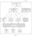
- FIG. 2 is a schematic diagram of a structure of an optical transmission device 200 according to an embodiment of this application.
- the optical transmission device 200 includes a tributary board 201, an electric cross unit 202, active line boards (203A, 203B, and 203C), a protection line board 203D, a first multiplexer/demultiplexer board 204, and an optical amplifier board 205.
- a quantity N of protection line boards is less than a quantity M of active line boards. Both M and N are positive integers, and N is greater than or equal to 1.
- a total quantity of tributary boards 201 may be the same as or different from that of active line boards.
- FIG. 2 shows an example of three tributary boards 201, three active line boards, and one protection line board. In another example, other quantities of active line boards and protection line boards, for example, 100 active line boards and 10 protection line boards, may be disposed.
- a first port of the tributary board 201 is configured to transmit client service data.
- the "transmit" herein may include send and/or receive.
- the tributary board 201 is responsible for receiving client service data from a client side in a first transmission direction, and is responsible for sending client service data to the client side in a second transmission direction.
- transmission actions in the first transmission direction and the second transmission direction may be performed simultaneously based on an actual service requirement.
- the tributary board 201, all the active line boards 203A to 203C, and the protection line board 203D are all electrically connected to the electric cross unit 202.
- the active line boards 203A to 203C, the protection line board 203D, and the optical amplifier board 205 are all optically connected to the first multiplexer/demultiplexer board 204.
- each tributary board corresponds to a different active line board 203A, 203B, or 203C.
- a signal processed by each tributary board 201 is scheduled by the electric cross unit 202, and sent to the active line board corresponding to the tributary board 201.
- signals processed by the active line boards 203A to 203C are scheduled by the electric cross unit 202, and sent to corresponding tributary boards 201.
- the first multiplexer/demultiplexer board 204 provides a multiplexing function in the first transmission direction, and provides a demultiplexing function in the second transmission direction.
- the first multiplexer/demultiplexer board 204 is configured to multiplex, to the optical amplifier board 205, optical waves provided by the active line boards 203A to 203C.
- the first multiplexer/demultiplexer board 204 is configured to demultiplex an optical wave from the optical amplifier board 205 to the active line boards 203A to 203C.
- the optical amplifier board 205 provides a function of amplifying optical power in the first transmission direction and the second transmission direction.
- the optical transmission device 200 is used as a local optical transmission device
- a second port of the optical amplifier board 205 is a port that is on the optical amplifier board 205 and that establishes an optical connection to a peer optical transmission device, and the second port is configured to transmit an optical signal that carries client service data.
- the "transmit" herein may include send and/or receive.
- the optical amplifier board 205 includes a first OA and a second OA.
- the first OA works in the first transmission direction
- the second OA works in the second transmission direction.
- the optical amplifier board 205 includes a multi-stage OA, and the multi-stage OA is configured to amplify, stage by stage, an optical signal received by the optical amplifier board 205.
- a trigger condition for enabling the protection line board 203D is preset.
- the first preset condition includes: at least one active line board is faulty or the optical transmission device 200 receives a line board switching instruction.
- Trigger scenario an active line board is faulty.
- the active line boards 203A and 203B work normally, the active line board 203C is faulty, and the protection line board 203D is in an idle state. Based on the foregoing description, it may be determined that the optical transmission device 200 meets the first preset condition. To enable the optical transmission device 200 to work normally and not to be affected by the faulty active line board 203C, the protection line board 203D needs to work in place of the faulty active line board 203C.
- the electric cross unit 202 of the optical transmission device 200 is configured to transmit, to the protection line board 203D for processing, client service data that is to be processed by the faulty active line board 203C.
- the client service data that is to be processed by the active line board 203C is specifically client service data carried in a signal that is to be sent to the active line board 203C when the active line board 203C is in a normal state.
- the first transmission direction is used as an example.
- the electric cross unit 202 may copy client service data that is to be processed by any active line board 203A, 203B, or 203C, and send a copy to the protection line board 203D. If the client service data that is copied and sent in advance is exactly the client service data that is to be processed by the active line board 203C, the optical transmission device 200 may directly enable the protection line board 203D when the active line board 203C is faulty.
- the electric cross unit 202 needs to temporarily schedule, to the protection line board 203D, the client service data that is to be processed by the active line board 203C.
- the electric cross unit 202 may not perform a pre-copy operation.
- the electric cross unit 202 temporarily schedules, to the protection line board 203D, client service data that is to be processed by the faulty active line board.
- a copying or scheduling operation in the second transmission direction is similar to that in the first transmission direction, and details are not described herein again.
- a controller outside the optical transmission device 200 may generate a line board switching instruction based on signal processing of each line board or based on a requirement for working sustainability of the optical transmission device when no line board is faulty, and send the instruction to the optical transmission device 200 to actively switch a working line board.
- the line board switching instruction may carry an identifier of a switched-from line board and an identifier of a switched-to line board. After receiving the line board switching instruction, the optical transmission device 200 switches work of the active line board 203C to the protection line board 203D for execution.
- the operation of copying or scheduling, by the electric cross unit 202 to the protection line board 203D, the client service data that is to be processed by the active line board 203C may be understood as changing an original correspondence of the tributary board 201 with a line board.
- the tributary board 201 originally corresponding to the active line board 203C is changed to corresponding to the protection line board 203D.
- the protection line board may be enabled in the optical transmission device to function in place of the active line board. This implements redundancy protection for the optical transmission device. Because the quantity of protection line boards is less than the quantity of active line boards, that is, the line boards in the optical transmission device are not subject to 1:1 dual configurations, a protection function of a protection line board may be shared by a plurality of active line boards. For example, if one protection line board is disposed in the optical transmission device, redundancy protection for the M active line boards is implemented by the one protection line board. If the quantity N of protection line boards is greater than 1, redundancy protection for the M active line boards is implemented by the N protection line boards. Compared with an existing solution, the optical transmission device provided in this embodiment reduces a quantity of configured line boards, and can reduce device costs.
- a multiplexer/demultiplexer board in an optical transmission device is generally optically connected to a plurality of line boards.
- the first multiplexer/demultiplexer board 204 is connected to the active line boards 203A to 203C.
- one multiplexer/demultiplexer board may be connected to dozens or even hundreds of line boards.
- Working performance of the multiplexer/demultiplexer board affects working reliability of the entire optical transmission device. Similar to the line board, the multiplexer/demultiplexer board may also fail. When a multiplexer/demultiplexer board is faulty, all services related to the multiplexer/demultiplexer board are affected if no other board functions in place of the board.
- the first multiplexer/demultiplexer board is configured to optically connect to 10 line boards. If a second multiplexer/demultiplexer board is used to perform redundancy protection for the first multiplexer/demultiplexer board, usually, 10 matched line boards optically connected to the second multiplexer/demultiplexer board need to be added.
- this application further provides another optical transmission device.
- An optical connection element is disposed on the line board, to release the inherent binding relationship between the multiplexer/demultiplexer board and the line board. Therefore, it is unnecessary to add a large quantity of matched line boards for redundancy protection of the multiplexer/demultiplexer board.
- FIG. 3 is a schematic diagram of a structure of the optical transmission device 400. Compared with the optical transmission device 200 shown in FIG. 2 , the optical transmission device 400 further includes a second multiplexer/demultiplexer board 401, as shown in FIG. 3 .
- the optical transmission device 400 includes one first multiplexer/demultiplexer board 204 and one second multiplexer/demultiplexer board 401.
- other quantities of first multiplexer/demultiplexer boards 204 and second multiplexer/demultiplexer boards 401 may be disposed.
- five first multiplexer/demultiplexer boards 204 and three second multiplexer/demultiplexer boards 401 are disposed.
- a quantity of first multiplexer/demultiplexer boards 204 is greater than or equal to a quantity of second multiplexer/demultiplexer boards 401.
- the first multiplexer/demultiplexer board 204 is used as an active board
- the second multiplexer/demultiplexer board 401 is used as a protection board.
- a trigger condition for enabling the second multiplexer/demultiplexer board 401 is preset.
- the optical transmission device 400 may enable the second multiplexer/demultiplexer board 401 in a plurality of trigger scenarios. Therefore, the second preset condition is set based on different trigger scenarios.
- the second preset condition includes: at least one first multiplexer/demultiplexer board is faulty or the optical transmission device 400 receives a multiplexer/demultiplexer board switching instruction.
- All the line boards 203A to 203D and the optical amplifier board 205 each include an optical connection element.
- the optical connection element is configured to establish an optical channel between a board on which the optical connection element is located and the first multiplexer/demultiplexer board 204.
- the optical connection element is configured to establish an optical channel between the board on which the optical connection element is located and the second multiplexer/demultiplexer board 401.
- the optical connection element of the active line board 203A, 203B, or 203C is configured to establish an optical channel between the active line board and the second multiplexer/demultiplexer board 401
- the optical connection element of the protection line board 203D is configured to establish an optical channel between the protection line board 203D and the second multiplexer/demultiplexer board 401
- the optical connection element of the optical amplifier board 205 is configured to establish an optical channel between the optical amplifier board 205 and the second multiplexer/demultiplexer board 401.
- the following specifically describes the two trigger scenarios of enabling the second multiplexer/demultiplexer board 401.
- Trigger scenario the first multiplexer/demultiplexer board is faulty.
- the second preset condition includes: at least one first multiplexer/demultiplexer board 204 is faulty.
- the second multiplexer/demultiplexer board 402 is in an idle state. Based on the foregoing description, it may be learned that the optical transmission device 400 meets the second preset condition. To enable the optical transmission device 400 to work normally and not to be affected by the faulty first multiplexer/demultiplexer board 204, the second multiplexer/demultiplexer board 402 needs to work in place of the faulty first multiplexer/demultiplexer board 204.
- the second multiplexer/demultiplexer board 401 and the first multiplexer/demultiplexer board 204 are the same, after optical connection elements of common upstream and downstream boards (the optical amplifier board 205 and the working line boards 203A to 203C) of the first multiplexer/demultiplexer board 204 and the second multiplexer/demultiplexer board 401 establish optical channels between the second multiplexer/demultiplexer board 401 and the boards on which the optical connection elements are located, the second multiplexer/demultiplexer board 401 may be smoothly enabled to function in place of the faulty first multiplexer/demultiplexer board 204.
- the second multiplexer/demultiplexer board 402 receives optical waves of the working line boards 203A to 203C, and multiplexes the optical waves to the optical amplifier board 205.
- the second multiplexer/demultiplexer board 402 receives an optical wave from the optical amplifier board 205, and then demultiplexes the optical wave to the active line boards 203A to 203C.
- the second preset condition includes: the optical transmission device 400 receives a multiplexer/demultiplexer board switching instruction sent by a controller outside.
- the multiplexer/demultiplexer board switching instruction may carry an identifier of a switched-from multiplexer/demultiplexer board and an identifier of a switched-to multiplexer/demultiplexer board.
- the optical transmission device 400 switches work of the first multiplexer/demultiplexer board 204 to the second multiplexer/demultiplexer board 401 for execution, and the first multiplexer/demultiplexer board 204 is disabled.
- the optical connection element establishes the optical channel between the board on which the optical connection element is located and the second multiplexer/demultiplexer board 402 may be understood as changing a correspondence of the board on which the optical connection element is located with a multiplexer/demultiplexer board.
- the board (the line boards 203A to 203D or the optical amplifier board 205) originally corresponding to the first multiplexer/demultiplexer board 201 is changed to corresponding to the second multiplexer/demultiplexer board 401.
- optical connection elements included on upstream and downstream boards of the first multiplexer/demultiplexer board 204 establish optical channels between the second multiplexer/demultiplexer board 401 and the boards, so that the optical transmission device 400 may enable the second multiplexer/demultiplexer board 401 to function in place of the first multiplexer/demultiplexer board 204.
- This implements redundancy protection for the multiplexer/demultiplexer board of the optical transmission device 400. In this way, even if the first multiplexer/demultiplexer board 204 is faulty, the optical transmission device 400 is not affected, and the optical transmission device 400 can work normally.
- the second multiplexer/demultiplexer board 401 and the optical connection elements of the upstream and downstream boards of the second multiplexer/demultiplexer board release the binding relationship between the line board and the multiplexer/demultiplexer board, and release the binding relationship between the optical amplifier board and the multiplexer/demultiplexer board. Therefore, redundancy protection for the multiplexer/demultiplexer board is implemented at relatively low redundancy protection costs, and reliability of working of the optical transmission device 400 is improved.
- the optical connection element may include two connection sub-elements.
- a first connection sub-element is configured to: when the optical transmission device 400 meets the second preset condition in the first transmission direction, establish an optical channel between a board on which the optical connection element is located and the second multiplexer/demultiplexer board 401.
- a second connection sub-element is configured to: when the optical transmission device 400 meets the second preset condition in the second transmission direction, establish an optical channel between the board on which the optical connection element is located and the second multiplexer/demultiplexer board 401.
- the optical channel to the second multiplexer/demultiplexer board 401 may be established only by using the first connection sub-element, to implement normal optical transmission in the first transmission direction.
- the second connection sub-element is still connected to the first multiplexer/demultiplexer board 204.
- the optical channel to the second multiplexer/demultiplexer board 401 may be established only by using the second connection sub-element, to implement normal optical transmission in the second transmission direction.
- the first connection sub-element is still connected to the first multiplexer/demultiplexer board 204.
- both the first connection sub-element and the second connection sub-element are connected to the second multiplexer/demultiplexer board 401. That is, the second multiplexer/demultiplexer board 401 functions in place of the first multiplexer/demultiplexer board 204 in both the first transmission direction and the second transmission direction.
- the first connection sub-element may be an optical selection element or an optical splitting element
- the second connection sub-element may be an optical selection element.
- the optical selection element as a first connection sub-element implements selective transmission of an optical signal, that is, selectively sends the optical signal to the second multiplexer/demultiplexer board 401
- the optical splitting element as a first connection sub-element implements dual transmission of an optical signal, that is, respectively sends the optical signal to the first multiplexer/demultiplexer board 204 and the second multiplexer/demultiplexer board 401
- the optical selection element as a second connection sub-element implements selective reception of an optical signal, that is, selectively receives an optical signal from the second multiplexer/demultiplexer board 401.
- FIG. 4 shows a schematic diagram of establishing an optical channel to the second multiplexer/demultiplexer board 402 by using an optical selection element and an optical splitting element as first connection sub-elements.
- a solid connection line between the active line board 203A and the second multiplexer/demultiplexer board 401 represents an optical channel established by using the optical selection element as a first connection sub-element.
- the optical splitting element is used as a first connection sub-element
- both the solid connection line and a dashed connection line in FIG. 4 represent optical paths turned on.
- the line board uses the optical selection element as a second connection sub-element, refer to the solid connection line in FIG. 4 for a schematic diagram of establishing an optical channel to the second multiplexer/demultiplexer board 402 by the optical selection element.
- the first connection sub-element may be an optical selection element
- the second connection sub-element may be an optical selection element or an optical splitting element.
- the optical selection element as a first connection sub-element implements selective reception of an optical signal, that is, selectively receives an optical signal from the second multiplexer/demultiplexer board 401
- the optical selection element as a second connection sub-element implements selective transmission of an optical signal, that is, selectively sends the optical signal to the second multiplexer/demultiplexer board 401
- the optical splitting element as a second connection sub-element implements dual transmission of an optical signal, that is, respectively sends the optical signal to the first multiplexer/demultiplexer board 204 and the second multiplexer/demultiplexer board 401
- the optical selection element as a second sub-connection element implements selective reception of an optical signal.
- FIG. 5 shows a schematic diagram of establishing an optical channel to the second multiplexer/demultiplexer board 402 by using an optical selection element and an optical splitting element as second connection sub-elements.
- a solid connection line between the optical amplifier board 205 and the second multiplexer/demultiplexer board 401 represents an optical channel established by using the optical selection element as a second connection sub-element.
- the optical splitting element is used as a second connection sub-element
- both the solid connection line and a dashed connection line in FIG. 5 represent optical paths turned on.
- the optical amplifier board 205 uses the optical selection element as a first connection sub-element, refer to FIG. 5 for a schematic diagram of establishing an optical channel to the second multiplexer/demultiplexer board 402 by the optical selection element.
- the optical splitting element provides a dual transmission function
- two output ends of the optical splitting element are respectively connected to the first multiplexer/demultiplexer board 204 and the second multiplexer/demultiplexer board 401.
- the optical splitting element respectively provides the optical signal to the first multiplexer/demultiplexer board 204 and the second multiplexer/demultiplexer board 401 after optical splitting along two optical paths.
- the optical splitting element has an optical splitting function, power of an optical signal output by the optical splitting element along a single optical path is lower than that of an optical signal at an input end of the optical splitting element. Therefore, when a transmission distance between the local optical transmission device and the peer optical transmission device is relatively short, it is appropriate to use the optical splitting element in the optical connection element of the local optical transmission device to implement a dual transmission function.
- the optical selection element shown in FIG. 4 and FIG. 5 is an optical switch, and an optical path is selected in a dimension of a spatial optical path by using the optical switch.
- each working line board corresponds to a different optical wavelength.
- the active line board 203A corresponds to a first wavelength
- the active line board 203B corresponds to a second wavelength
- the active line board 203C corresponds to a third wavelength.
- each line board of the optical transmission device 400 may be a line board with relatively high integration, and includes a plurality of submodules, and each submodule corresponds to a plurality of different optical wavelengths.
- each optical amplifier board 205 may be an optical amplifier board with relatively high integration, and includes a plurality of submodules, and each submodule corresponds to a plurality of different optical wavelengths.
- a wavelength selective element may be used as an optical selection element. Light is selected in a dimension of an optical wavelength by using the wavelength selective element.
- a wavelength selective element of the line board is used as an example.
- the wavelength selective element of the line board establishes an optical channel to the second multiplexer/demultiplexer board 401, and sends light of a first wavelength to the second multiplexer/demultiplexer board 401.
- FIG. 6 is a schematic diagram of enabling the protection line board 203D and the second multiplexer/demultiplexer board 401 by the optical transmission device 400. As shown in FIG. 6 , the protection line board 203D works in place of the active line board 203C, and the second multiplexer/demultiplexer board 401 works in place of the first multiplexer/demultiplexer board 204.
- the optical transmission devices 200 and 400 may further include a first controller.
- the following describes an implementation and a function of the first controller by using the optical transmission device 400 as an example.
- each board (for example, the tributary board 201, the electric cross unit 202, the line boards 203A to 203D, the first multiplexer/demultiplexer board 204, the second multiplexer/demultiplexer board 401, and the optical amplifier board 205) may be electrically connected to the first controller.
- the electrical connection may be a wired connection or a wireless connection.
- Each board electrically connected to the first controller may communicate with the first controller.
- Each board may implement fault self-detection, or fault detection may be implemented by an upstream or downstream board of the board.
- the line boards 203A to 203D may feed back fault detection results to the first controller after fault self-detection, or the electric cross unit 202 or a working multiplexer/demultiplexer board (the first multiplexer/demultiplexer board 204 or the second multiplexer/demultiplexer board 401) may feed back fault detection results to the first controller after performing fault detection on the line boards. If a fault detection result indicates that a line board is faulty, the optical transmission device 400 meets the first preset condition.
- the first controller may be configured to control scheduling of the electric cross unit 202 and the working multiplexer/demultiplexer board (for example, the first multiplexer/demultiplexer board 204), for example, scheduling client service data that is to be processed by the faulty active line board 203C to the idle protection line board 203D, and scheduling, to the protection line board 203D, an optical signal that is to be scheduled by the first multiplexer/demultiplexer board 204 to the active line board 203C.
- the working multiplexer/demultiplexer board for example, the first multiplexer/demultiplexer board 204
- the first multiplexer/demultiplexer board 204 may feed back a fault detection result to the first controller after fault self-detection, or the optical amplifier board 205 or a working line board may feed back a fault detection result to the first controller after performing fault detection on the first multiplexer/demultiplexer board. If the fault detection result indicates that the first multiplexer/demultiplexer board is faulty, the optical transmission device 400 meets the second preset condition.
- the first controller may be configured to control both the working line board in the line boards 203A to 203D and the optical amplifier board 205 to establish an optical channel to the second multiplexer/demultiplexer board 401.
- the first controller may send a control instruction to a corresponding board, to enable the protection line board 203D or the second multiplexer/demultiplexer board 401.
- the first controller may receive a line board switching instruction or a multiplexer/demultiplexer board switching instruction sent by a controller outside the device, and then control a board inside the device to enable a switched-to line board or multiplexer/demultiplexer board.
- the optical transmission device 400 further includes an input module (for example, a touchscreen or a keyboard), and the input module is electrically connected to the first controller, the input module may send a line board switching instruction or a multiplexer/demultiplexer board switching instruction to the first controller in response to an operation of a user.
- the first multiplexer/demultiplexer board 204 may be implemented by using a wavelength selective switch (Wavelength Selective Switch, WSS), or implemented by using a multiplexer and a demultiplexer.
- WSS wavelength selective switch
- An implementation of the second multiplexer/demultiplexer board 401 is similar to the implementation of the first multiplexer/demultiplexer board 204, and details are not described herein again.
- the protection line board is optional.
- the optical transmission device includes a tributary-line board.
- a protection multiplexer/demultiplexer board is disposed in the optical transmission device, which can also improve stability of working of the device.
- FIG. 7 is a schematic diagram of a structure of still another optical transmission device 900 according to an embodiment of this application.
- the optical transmission device 900 includes tributary-line boards 901A to 901C, a first multiplexer/demultiplexer board 204, a second multiplexer/demultiplexer board 401, and an optical amplifier board 205.
- FIG. 7 shows only three tributary-line boards, one first multiplexer/demultiplexer board 204, and one second multiplexer/demultiplexer board 401. In actual application, other quantities of boards may be disposed based on an actual requirement.
- first multiplexer/demultiplexer boards 204 For example, 20 tributary-line boards, five first multiplexer/demultiplexer boards 204, and three second multiplexer/demultiplexer boards 401 are disposed.
- a quantity of first multiplexer/demultiplexer boards 204 is greater than or equal to a quantity of second multiplexer/demultiplexer boards 401.
- First ports of the tributary-line boards 901A to 901C are configured to transmit client service data.
- the tributary-line boards 901A to 901C and the optical amplifier board 205 include optical connection elements.
- the optical connection elements are configured to establish optical channels to the second multiplexer/demultiplexer board 401.
- the second preset condition is described in the foregoing embodiment, and reference may be made to the foregoing embodiment.
- the device 900 is not affected even if the first multiplexer/demultiplexer board 204 is faulty. Therefore, stability of working of the optical transmission device 900 is improved. If the quantity of second multiplexer/demultiplexer boards 401 is less than the quantity of first multiplexer/demultiplexer boards 204, a backup function of a second multiplexer/demultiplexer board 401 may be shared by a plurality of first multiplexer/demultiplexer boards 204, thereby reducing redundancy protection costs for the optical transmission device 900.
- the second multiplexer/demultiplexer board 401 and the optical connection elements of the upstream and downstream boards of the second multiplexer/demultiplexer board release a binding relationship between the tributary-line board and the first multiplexer/demultiplexer board, and release a binding relationship between the optical amplifier board and the multiplexer/demultiplexer board. Therefore, redundancy protection for the multiplexer/demultiplexer board is implemented at relatively low redundancy protection costs, and reliability of working of the optical transmission device 900 is improved.
- optical connection element included on the optical amplifier board 205 is described in detail, and details are not described again in this embodiment.
- the following describes an implementation of the optical connection elements disposed on the tributary-line boards 901A to 901C.
- a first connection sub-element may be an optical selection element or an optical splitting element
- a second connection sub-element may be an optical selection element.
- the optical selection element as a first connection sub-element implements selective transmission of an optical signal, that is, selectively sends the optical signal to the second multiplexer/demultiplexer board 401
- the optical splitting element as a first connection sub-element respectively sends an optical signal to the first multiplexer/demultiplexer board 204 and the second multiplexer/demultiplexer board 401
- the optical selection element as a second connection sub-element implements selective reception of an optical signal, that is, selectively receives an optical signal from the second multiplexer/demultiplexer board 401.
- a manner in which an optical connection element is disposed on the tributary-line board 901A of the optical transmission device 900 is basically the same as the manner in which an optical connection element is disposed on the active line board 203A of the optical transmission device 400, and reference may be made to FIG. 4 .
- the optical transmission device 900 may further include a second controller.
- the tributary-line boards 901A to 901C, the first multiplexer/demultiplexer board 204, the second multiplexer/demultiplexer board 401, and the optical amplifier board 205 may be all electrically connected to the second controller.
- the second controller is configured to control each working tributary-line board and the optical amplifier board 205 to establish an optical channel to the second multiplexer/demultiplexer board 401.
- An implementation in which the second controller determines a fault detection result and controls the boards is similar to that of the first controller, and reference may be made to the first controller described in the foregoing embodiment.
- the boards included in the device may be distributed in a relatively small space range, to form an integrated optical transmission device.
- the boards are disposed or integrated in one device room.
- the boards included in the device may be distributed in a relatively large space range, to form a plurality of sub-devices separated from each other.
- the tributary board, the electric cross unit, and the multiplexer/demultiplexer board of the optical transmission device 200 are disposed on a first sub-device
- the optical amplifier board is disposed on a second sub-device
- the first sub-device and the second sub-device are respectively located in different device rooms.
- a spatial form of the optical transmission device and a distribution position of the board are not limited in the embodiments of this application.
- this application further provides an optical transmission system.
- the following describes a specific implementation of the system with reference to an embodiment and FIG. 1 .
- the optical transmission scenario shown in FIG. 1 also shows an optical transmission system, including the optical transmission device C1 and the optical transmission device C2.
- C1 and C2 may be optical transmission devices shown in FIG. 2 and FIG. 3 .
- a second port of an optical amplifier board 205 of the optical transmission device C1 is optically connected to a second port of an optical amplifier board 205 of the optical transmission device C2.
- the two second ports may be connected through an optical fiber.
- At least one optical amplifier site is further disposed on a transmission path between the optical transmission devices C1 and C2.
- the second port of the optical amplifier board 205 of the optical transmission device C1 may be connected to the second port of the optical amplifier board 205 of the optical transmission device C2 through the at least one optical amplifier site.
- optical transmission device C1 if a first preset condition is met, an active line board is switched to a protection line board, and the protection line board performs corresponding work.
- optical transmission may be performed along two opposite directions.
- functions of boards of the optical transmission device C2 in the optical transmission system in a signal processing process and an implementation of enabling a protection line board refer to the foregoing description.
- protection line boards of the optical transmission devices C1 and C2 may establish connections to upstream and downstream boards (multiplexer/demultiplexer boards and electric cross units), when either of the optical transmission devices meets the first preset condition, an electric cross unit performs an operation of copying or scheduling client service data that is to be processed by an active line board, so that a protection line board may be enabled in the optical transmission device to function in place of the active line board.
- This implements redundancy protection for the optical transmission system. Because a quantity of protection line boards is less than a quantity of active line boards, a protection function of a protection line board may be shared by a plurality of active line boards of an optical transmission device to which the protection line board belongs, thereby reducing device costs.
- a second multiplexer/demultiplexer board 401 may work in place of a first multiplexer/demultiplexer board 204.
- the second multiplexer/demultiplexer board 401 of the optical transmission device improves reliability of working of the optical transmission system.
- this application further provides an optical transmission method.
- the following describes a specific implementation of the method with reference to an embodiment by using a local optical transmission device as a description body.
- the optical transmission method provided in this embodiment of this application includes: When the optical transmission device meets a first preset condition, the electric cross unit 202 of the optical transmission device copies or schedules, to the protection line board 302, client service data that is to be processed by an active line board, and the first multiplexer/demultiplexer board performs multiplexing and demultiplexing in cooperation with the protection line board.
- the electric cross unit 202 schedules, to the protection line board 203D, client service data that is to be processed by the active line board 203C. For another example, if a line board switching instruction received by the optical transmission device instructs to switch from the active line board 203C to the protection line board 203D, the electric cross unit 202 schedules, to the protection line board 203D, client service data that is to be processed by the active line board 203C.
- optical transmission method provided in this embodiment of this application, the following separately describes, from two transmission directions, operations performed by the optical transmission device when the optical transmission device meets the first preset condition.
- the tributary board 201 receives client service data; the electric cross unit 202 copies or schedules, to the protection line board 203D, the client service data that is to be processed by an active line board (which is faulty or needs to be switched); the protection line board 203D performs electrical-to-optical conversion on the client service data; the first multiplexer/demultiplexer board 204 receives an optical signal provided by the protection line board 203D, to perform multiplexing; and the optical amplifier board 205 amplifies a multiplexed optical signal, and transmits an amplified optical signal to a peer transmission device, where the optical signal carries the client service data.
- the optical amplifier board 205 receives and amplifies an optical signal of the peer device; the first multiplexer/demultiplexer board 204 demultiplexes an amplified optical signal to corresponding line boards, where the corresponding line boards include the protection line board 203D; the protection line board 203D performs optical-to-electrical conversion on a received optical signal and then provides client service data to the electric cross unit 202; and the electric cross unit 202 performs scheduling to send, to a client side through the first port of the tributary board 201, the client service data obtained through processing by the protection line board 203D.
- a protection function of a protection line board may be shared by a plurality of active line boards, so that redundancy protection costs can be reduced.
- this application further provides an optical transmission method, to improve reliability of working of the optical transmission device 400.
- the optical transmission device 400 shown in FIG. 3 further includes the second multiplexer/demultiplexer board 401 in addition to the first multiplexer/demultiplexer board 204.
- the optical transmission method includes: when the optical transmission device 400 meets a second preset condition, establishing an optical channel between the second multiplexer/demultiplexer board 401 and a working line board in the active line board and the protection line board, and establishing an optical channel between the optical amplifier board 205 and the second multiplexer/demultiplexer board 401.
- this application further provides an optical transmission method, to improve reliability of working of the optical transmission device 900.
- the optical transmission device shown in FIG. 7 further includes the second multiplexer/demultiplexer board 401 in addition to the first multiplexer/demultiplexer board 204.
- the optical transmission method includes: when the optical transmission device 900 meets a second preset condition, establishing an optical channel between the tributary-line board and the second multiplexer/demultiplexer board 401, and establishing an optical channel between the optical amplifier board 205 and the second multiplexer/demultiplexer board 401.
- the optical transmission device may enable the second multiplexer/demultiplexer board 401 to process and transmit an optical signal, so that the optical transmission device works normally. It can be learned that working reliability of the optical transmission devices shown in FIG. 3 and FIG. 7 is improved.
- At least one of a, b, or c may indicate a, b, c, a and b, a and c, b and c, or a, b, and c, where a, b, and c may be singular or plural.
Landscapes
- Engineering & Computer Science (AREA)
- Computer Networks & Wireless Communication (AREA)
- Signal Processing (AREA)
- Physics & Mathematics (AREA)
- Electromagnetism (AREA)
- Optics & Photonics (AREA)
- Optical Communication System (AREA)
Applications Claiming Priority (2)
| Application Number | Priority Date | Filing Date | Title |
|---|---|---|---|
| CN202010430503.8A CN113709601B (zh) | 2020-05-20 | 2020-05-20 | 一种光传输设备、系统及光传输方法 |
| PCT/CN2021/093267 WO2021233174A1 (zh) | 2020-05-20 | 2021-05-12 | 一种光传输设备、系统及光传输方法 |
Publications (2)
| Publication Number | Publication Date |
|---|---|
| EP4145846A1 true EP4145846A1 (de) | 2023-03-08 |
| EP4145846A4 EP4145846A4 (de) | 2023-11-15 |
Family
ID=78645615
Family Applications (1)
| Application Number | Title | Priority Date | Filing Date |
|---|---|---|---|
| EP21808530.6A Pending EP4145846A4 (de) | 2020-05-20 | 2021-05-12 | Optische übertragungsvorrichtung, system und verfahren |
Country Status (4)
| Country | Link |
|---|---|
| US (1) | US20230080248A1 (de) |
| EP (1) | EP4145846A4 (de) |
| CN (1) | CN113709601B (de) |
| WO (1) | WO2021233174A1 (de) |
Families Citing this family (4)
| Publication number | Priority date | Publication date | Assignee | Title |
|---|---|---|---|---|
| CN116184573A (zh) * | 2021-11-27 | 2023-05-30 | 华为技术有限公司 | 光交叉装置和光交叉设备 |
| CN116366157A (zh) * | 2021-12-27 | 2023-06-30 | 华为技术有限公司 | 光通信设备和光通信系统 |
| CN117353806A (zh) * | 2022-06-29 | 2024-01-05 | 中兴通讯股份有限公司 | 主干光路保护方法和系统、光矩阵设备、电子设备、介质 |
| CN115208460B (zh) * | 2022-07-29 | 2024-05-28 | 广东三德信息通讯科技有限公司 | 一种光连接热备保护装置 |
Family Cites Families (22)
| Publication number | Priority date | Publication date | Assignee | Title |
|---|---|---|---|---|
| US5777761A (en) * | 1995-12-22 | 1998-07-07 | Mci Communications Corporation | System and method for photonic facility and line protection switching using wavelength translation |
| US6307653B1 (en) * | 1999-03-24 | 2001-10-23 | Tellium, Inc | Optical matrix protection system |
| US7099578B1 (en) * | 1999-12-16 | 2006-08-29 | Tellabs Operations Inc. | 1:N protection in an optical terminal |
| US6414765B1 (en) * | 2000-03-07 | 2002-07-02 | Corning, Inc. | Protection switch in a two-fiber optical channel shared protection ring |
| US6906997B1 (en) * | 2000-09-08 | 2005-06-14 | Fujitsu Limited | Protection method and system for equipment in a network element |
| US20020105696A1 (en) * | 2001-02-07 | 2002-08-08 | Ross Halgren | Transparent optical-electronic-optical switch |
| US6690848B2 (en) * | 2001-06-29 | 2004-02-10 | Nortel Networks Limited | Metropolitan photonic switch |
| US7187865B2 (en) * | 2001-11-13 | 2007-03-06 | Nortel Networks Limited | Hybrid photonic/electronic switching in a multi-channel network |
| JP3910085B2 (ja) * | 2002-03-18 | 2007-04-25 | 富士通株式会社 | 光伝送装置 |
| CN1921357A (zh) * | 2006-09-21 | 2007-02-28 | 杭州华为三康技术有限公司 | 一种全光纤保护装置及其方法 |
| CN102652399B (zh) * | 2010-09-10 | 2014-07-30 | 华为技术有限公司 | 光接口线路板的冗余备份方法、系统及光接口线路板 |
| CN105099506A (zh) * | 2015-08-21 | 2015-11-25 | 江阴长仪集团有限公司 | 一种电能表rs485通信故障检测自愈的装置及方法 |
| CN105721045B (zh) * | 2016-01-19 | 2018-08-21 | 华为技术有限公司 | 一种保护倒换的方法和节点 |
| CN109151830B (zh) * | 2017-06-15 | 2022-07-29 | 华为技术有限公司 | 一种频谱整理的方法、装置、设备和系统 |
| CN108092734B (zh) * | 2017-11-13 | 2019-08-16 | 广州供电局有限公司 | 电力数据传输设备、系统及检测方法 |
| CN107846247B (zh) * | 2017-11-14 | 2019-08-06 | 烽火通信科技股份有限公司 | 一种保护倒换系统及方法 |
| US10187063B1 (en) * | 2017-11-29 | 2019-01-22 | Arm Limited | Sequential logic device with single-phase clock operation |
| CN208508943U (zh) * | 2018-06-13 | 2019-02-15 | 中国移动通信集团广东有限公司 | 一种光纤线路监测系统 |
| CN110708254B (zh) * | 2018-07-09 | 2023-04-18 | 华为技术有限公司 | 一种业务处理方法、控制设备及存储介质 |
| CN109361453A (zh) * | 2018-10-15 | 2019-02-19 | 江西山水光电科技股份有限公司 | 一种otn传送网设备中的主备倒换电路及倒换方法 |
| CN109542693A (zh) * | 2018-11-27 | 2019-03-29 | 郑州云海信息技术有限公司 | 一种基于bios芯片备用功能的电路系统及其设计方法 |
| CN111082890B (zh) * | 2019-11-11 | 2021-07-27 | 国家电网有限公司 | 基于otn富余波的olp通道保护切换方法 |
-
2020
- 2020-05-20 CN CN202010430503.8A patent/CN113709601B/zh active Active
-
2021
- 2021-05-12 WO PCT/CN2021/093267 patent/WO2021233174A1/zh unknown
- 2021-05-12 EP EP21808530.6A patent/EP4145846A4/de active Pending
-
2022
- 2022-11-18 US US17/990,342 patent/US20230080248A1/en active Pending
Also Published As
| Publication number | Publication date |
|---|---|
| US20230080248A1 (en) | 2023-03-16 |
| EP4145846A4 (de) | 2023-11-15 |
| CN113709601B (zh) | 2022-10-28 |
| WO2021233174A1 (zh) | 2021-11-25 |
| CN113709601A (zh) | 2021-11-26 |
Similar Documents
| Publication | Publication Date | Title |
|---|---|---|
| EP4145846A1 (de) | Optische übertragungsvorrichtung, system und verfahren | |
| US7447398B2 (en) | Optical crossconnect apparatus | |
| EP2493096B1 (de) | Verfahren, system und vorrichtung für den schutz eines bidirektionalen einzelfaserringnetzes | |
| JP4899589B2 (ja) | 光ネットワーク、光ネットワークのプロテクション方法及びノード | |
| CA2489954C (en) | Wdm layer-based ochp device and method thereof | |
| CA2590902A1 (en) | Method and apparatus for protecting optical signals within a wavelength division multiplexed environment | |
| US20070195693A1 (en) | Method and device for implementing och-spring in wavelength division multiplexing systems | |
| EP3057247B1 (de) | Vorrichtung für rekonfigurierbaren optischen add/drop-multiplexer | |
| CN106605381B (zh) | 光网络中的可重新配置的分插复用器 | |
| CA2394599A1 (en) | Four-fiber ring optical cross-connect system using 4x4 switch matrices | |
| US6185021B1 (en) | Cross-connecting optical translator array | |
| EP1064739B1 (de) | Wellenlängenmultiplexkanalschutz | |
| KR100989676B1 (ko) | 파장 분할 다중화 시스템에서 광 회선 분배 장치 및 방법 | |
| US7146102B2 (en) | Optical cross-connect device | |
| ES2977819T3 (es) | Dispositivo AMCC y procedimiento de ajuste y control de la longitud de onda de transmisión. | |
| US20020071154A1 (en) | Shared optical ring protection in a multi-fiber ring | |
| EP2434774B1 (de) | Vorrichtung und verfahren für einen farblosen optischen schalter | |
| WO2023061297A1 (zh) | 一种波分复用设备及光信号处理方法 | |
| JP5558220B2 (ja) | 光ネットワークシステムのノード装置 | |
| EP3113389B1 (de) | Wellenlängenredundanzvorrichtung und wellenlängenredundanzverfahren | |
| JP2007067952A (ja) | 光スイッチ装置、光アクセスネットワーク、そのシステム、光波長多重伝送方法およびプログラム | |
| CN109802744B (zh) | 可重构光分插复用器、光网络及光信号处理方法 | |
| US11811448B2 (en) | Optical communication system, optical communication apparatus and optical communication method | |
| JPH10107734A (ja) | 光送受信システムにおける無瞬断切替方法 | |
| JP2010080996A (ja) | 光送信装置、光受信装置及び波長多重光伝送システム |
Legal Events
| Date | Code | Title | Description |
|---|---|---|---|
| STAA | Information on the status of an ep patent application or granted ep patent |
Free format text: STATUS: THE INTERNATIONAL PUBLICATION HAS BEEN MADE |
|
| PUAI | Public reference made under article 153(3) epc to a published international application that has entered the european phase |
Free format text: ORIGINAL CODE: 0009012 |
|
| STAA | Information on the status of an ep patent application or granted ep patent |
Free format text: STATUS: REQUEST FOR EXAMINATION WAS MADE |
|
| 17P | Request for examination filed |
Effective date: 20221201 |
|
| AK | Designated contracting states |
Kind code of ref document: A1 Designated state(s): AL AT BE BG CH CY CZ DE DK EE ES FI FR GB GR HR HU IE IS IT LI LT LU LV MC MK MT NL NO PL PT RO RS SE SI SK SM TR |
|
| DAV | Request for validation of the european patent (deleted) | ||
| DAX | Request for extension of the european patent (deleted) | ||
| A4 | Supplementary search report drawn up and despatched |
Effective date: 20231016 |
|
| RIC1 | Information provided on ipc code assigned before grant |
Ipc: H04J 14/02 20060101ALI20231010BHEP Ipc: H04B 10/40 20130101ALI20231010BHEP Ipc: H04B 10/25 20130101ALI20231010BHEP Ipc: H04B 10/032 20130101ALI20231010BHEP Ipc: H04Q 11/00 20060101AFI20231010BHEP |