EP4145644A1 - Audiostecker - Google Patents
Audiostecker Download PDFInfo
- Publication number
- EP4145644A1 EP4145644A1 EP22193511.7A EP22193511A EP4145644A1 EP 4145644 A1 EP4145644 A1 EP 4145644A1 EP 22193511 A EP22193511 A EP 22193511A EP 4145644 A1 EP4145644 A1 EP 4145644A1
- Authority
- EP
- European Patent Office
- Prior art keywords
- ring
- section
- cables
- diameter
- head
- Prior art date
- Legal status (The legal status is an assumption and is not a legal conclusion. Google has not performed a legal analysis and makes no representation as to the accuracy of the status listed.)
- Pending
Links
- 238000011144 upstream manufacturing Methods 0.000 claims abstract description 17
- 210000000078 claw Anatomy 0.000 claims description 9
- 230000003247 decreasing effect Effects 0.000 claims description 9
- 230000000903 blocking effect Effects 0.000 abstract description 6
- 239000000463 material Substances 0.000 description 6
- 208000031968 Cadaver Diseases 0.000 description 5
- 230000000694 effects Effects 0.000 description 4
- 125000006850 spacer group Chemical group 0.000 description 4
- 239000004698 Polyethylene Substances 0.000 description 2
- 239000004743 Polypropylene Substances 0.000 description 2
- 229910052782 aluminium Inorganic materials 0.000 description 2
- XAGFODPZIPBFFR-UHFFFAOYSA-N aluminium Chemical compound [Al] XAGFODPZIPBFFR-UHFFFAOYSA-N 0.000 description 2
- 230000015572 biosynthetic process Effects 0.000 description 2
- 239000007924 injection Substances 0.000 description 2
- 238000002347 injection Methods 0.000 description 2
- 229910052751 metal Inorganic materials 0.000 description 2
- 239000002184 metal Substances 0.000 description 2
- 239000004033 plastic Substances 0.000 description 2
- 229920003023 plastic Polymers 0.000 description 2
- -1 polyethylene Polymers 0.000 description 2
- 229920000573 polyethylene Polymers 0.000 description 2
- 229920001155 polypropylene Polymers 0.000 description 2
- 229910000679 solder Inorganic materials 0.000 description 2
- 238000004804 winding Methods 0.000 description 2
- 229910000906 Bronze Inorganic materials 0.000 description 1
- RYGMFSIKBFXOCR-UHFFFAOYSA-N Copper Chemical compound [Cu] RYGMFSIKBFXOCR-UHFFFAOYSA-N 0.000 description 1
- 239000004677 Nylon Substances 0.000 description 1
- 229910000831 Steel Inorganic materials 0.000 description 1
- 239000004809 Teflon Substances 0.000 description 1
- 229920006362 Teflon® Polymers 0.000 description 1
- 239000010974 bronze Substances 0.000 description 1
- 229910052802 copper Inorganic materials 0.000 description 1
- 239000010949 copper Substances 0.000 description 1
- KUNSUQLRTQLHQQ-UHFFFAOYSA-N copper tin Chemical compound [Cu].[Sn] KUNSUQLRTQLHQQ-UHFFFAOYSA-N 0.000 description 1
- 230000001627 detrimental effect Effects 0.000 description 1
- 229920001778 nylon Polymers 0.000 description 1
- 239000004417 polycarbonate Substances 0.000 description 1
- 229920000515 polycarbonate Polymers 0.000 description 1
- 239000004800 polyvinyl chloride Substances 0.000 description 1
- 238000000926 separation method Methods 0.000 description 1
- 238000005476 soldering Methods 0.000 description 1
- 239000010959 steel Substances 0.000 description 1
Images


Classifications
-
- H—ELECTRICITY
- H01—ELECTRIC ELEMENTS
- H01R—ELECTRICALLY-CONDUCTIVE CONNECTIONS; STRUCTURAL ASSOCIATIONS OF A PLURALITY OF MUTUALLY-INSULATED ELECTRICAL CONNECTING ELEMENTS; COUPLING DEVICES; CURRENT COLLECTORS
- H01R24/00—Two-part coupling devices, or either of their cooperating parts, characterised by their overall structure
- H01R24/58—Contacts spaced along longitudinal axis of engagement
-
- H—ELECTRICITY
- H01—ELECTRIC ELEMENTS
- H01R—ELECTRICALLY-CONDUCTIVE CONNECTIONS; STRUCTURAL ASSOCIATIONS OF A PLURALITY OF MUTUALLY-INSULATED ELECTRICAL CONNECTING ELEMENTS; COUPLING DEVICES; CURRENT COLLECTORS
- H01R13/00—Details of coupling devices of the kinds covered by groups H01R12/70 or H01R24/00 - H01R33/00
- H01R13/46—Bases; Cases
- H01R13/502—Bases; Cases composed of different pieces
- H01R13/512—Bases; Cases composed of different pieces assembled by screw or screws
-
- H—ELECTRICITY
- H01—ELECTRIC ELEMENTS
- H01R—ELECTRICALLY-CONDUCTIVE CONNECTIONS; STRUCTURAL ASSOCIATIONS OF A PLURALITY OF MUTUALLY-INSULATED ELECTRICAL CONNECTING ELEMENTS; COUPLING DEVICES; CURRENT COLLECTORS
- H01R13/00—Details of coupling devices of the kinds covered by groups H01R12/70 or H01R24/00 - H01R33/00
- H01R13/56—Means for preventing chafing or fracture of flexible leads at outlet from coupling part
- H01R13/565—Torsion-relieving
-
- H—ELECTRICITY
- H01—ELECTRIC ELEMENTS
- H01R—ELECTRICALLY-CONDUCTIVE CONNECTIONS; STRUCTURAL ASSOCIATIONS OF A PLURALITY OF MUTUALLY-INSULATED ELECTRICAL CONNECTING ELEMENTS; COUPLING DEVICES; CURRENT COLLECTORS
- H01R13/00—Details of coupling devices of the kinds covered by groups H01R12/70 or H01R24/00 - H01R33/00
- H01R13/58—Means for relieving strain on wire connection, e.g. cord grip, for avoiding loosening of connections between wires and terminals within a coupling device terminating a cable
- H01R13/5804—Means for relieving strain on wire connection, e.g. cord grip, for avoiding loosening of connections between wires and terminals within a coupling device terminating a cable comprising a separate cable clamping part
- H01R13/5816—Means for relieving strain on wire connection, e.g. cord grip, for avoiding loosening of connections between wires and terminals within a coupling device terminating a cable comprising a separate cable clamping part for cables passing through an aperture in a housing wall, the separate part being captured between cable and contour of aperture
-
- H—ELECTRICITY
- H01—ELECTRIC ELEMENTS
- H01R—ELECTRICALLY-CONDUCTIVE CONNECTIONS; STRUCTURAL ASSOCIATIONS OF A PLURALITY OF MUTUALLY-INSULATED ELECTRICAL CONNECTING ELEMENTS; COUPLING DEVICES; CURRENT COLLECTORS
- H01R11/00—Individual connecting elements providing two or more spaced connecting locations for conductive members which are, or may be, thereby interconnected, e.g. end pieces for wires or cables supported by the wire or cable and having means for facilitating electrical connection to some other wire, terminal, or conductive member, blocks of binding posts
- H01R11/11—End pieces or tapping pieces for wires, supported by the wire and for facilitating electrical connection to some other wire, terminal or conductive member
-
- H—ELECTRICITY
- H01—ELECTRIC ELEMENTS
- H01R—ELECTRICALLY-CONDUCTIVE CONNECTIONS; STRUCTURAL ASSOCIATIONS OF A PLURALITY OF MUTUALLY-INSULATED ELECTRICAL CONNECTING ELEMENTS; COUPLING DEVICES; CURRENT COLLECTORS
- H01R2105/00—Three poles
-
- H—ELECTRICITY
- H01—ELECTRIC ELEMENTS
- H01R—ELECTRICALLY-CONDUCTIVE CONNECTIONS; STRUCTURAL ASSOCIATIONS OF A PLURALITY OF MUTUALLY-INSULATED ELECTRICAL CONNECTING ELEMENTS; COUPLING DEVICES; CURRENT COLLECTORS
- H01R4/00—Electrically-conductive connections between two or more conductive members in direct contact, i.e. touching one another; Means for effecting or maintaining such contact; Electrically-conductive connections having two or more spaced connecting locations for conductors and using contact members penetrating insulation
- H01R4/02—Soldered or welded connections
- H01R4/021—Soldered or welded connections between two or more cables or wires
-
- H—ELECTRICITY
- H01—ELECTRIC ELEMENTS
- H01R—ELECTRICALLY-CONDUCTIVE CONNECTIONS; STRUCTURAL ASSOCIATIONS OF A PLURALITY OF MUTUALLY-INSULATED ELECTRICAL CONNECTING ELEMENTS; COUPLING DEVICES; CURRENT COLLECTORS
- H01R4/00—Electrically-conductive connections between two or more conductive members in direct contact, i.e. touching one another; Means for effecting or maintaining such contact; Electrically-conductive connections having two or more spaced connecting locations for conductors and using contact members penetrating insulation
- H01R4/02—Soldered or welded connections
- H01R4/023—Soldered or welded connections between cables or wires and terminals
Definitions
- the present invention relates to the audiovisual field, and relates in particular to an audio plug with several cables.
- Audio plugs are widely used in the audiovisual field and in particular for music.
- Audio plugs are application specific. Most of the time, audio plugs allow only one cable to be connected. There are thus audio plugs for mono application, the audio plug having a single mono cable, and audio plugs for stereo application, the audio plug having a single stereo cable. Some audio plugs, however, allow two cables to be connected to a single plug simultaneously for hybrid applications, where an audio plug for stereo application has two mono cables (so-called Y or insert type configuration) connected at the other end to two audio plugs for a mono app.
- the present invention aims to overcome this drawback and relates to an audio plug configured to attach to the end of at least two audio cables, the audio plug comprising a head and a body configured to attach to the head, the head comprising an audio connector part and connection terminals configured to connect the audio connector part to the at least two audio cables, a through opening being formed in a longitudinal direction through the body between the upstream end of the side body head, carrying means for fixing to the head, and the downstream end, the through opening corresponding to the internal surface of the body having a symmetry of revolution around the longitudinal direction and being configured to allow the passage of the at least two cables through the body from the downstream end to the connection terminals at the upstream end, characterized in that a shoulder is further formed on the inner surface of the body to form two rotationally symmetrical sections in the body , a first cylindrical section on the upstream side and a second section with rotational symmetry on the downstream side, the audio plug further comprising a ring whose outer surface has a shoulder to form two adjoining sections, a first cylindrical section
- the audio plug comprises a head and a body configured to be fixed on the head, the head comprising a part forming an audio connector and connection terminals configured to connect the part forming an audio connector to the at least two cables audio, a through-opening being formed in a longitudinal direction through the body between the upstream end of the head-side body, carrying means for attachment to the head, and the downstream end, the through-opening corresponding to the internal surface of the body having rotational symmetry around the longitudinal direction and being configured to allow passage of the at least two cables through the body from the downstream end to the connection terminals at the upstream end, a shoulder being further formed on the inner surface of the body to form two cylindrical sections in the body, a first upstream side cylindrical section and a second cylindrical section c downstream from smaller in diameter than the first cylindrical section on the upstream side, the audio plug further comprising a ring whose outer surface has a shoulder to form two adjoining cylindrical sections, a first section with a diameter corresponding to the diameter of the first cylindrical section on the upstream side
- the body is fixed on the head preferably by screwing.
- the body can also be clipped onto the head, without departing from the scope of the present invention.
- the purpose of the ring according to the invention is to prevent any tendency to torsion (winding up) of the cables one on the other, or even any separation (lateral movements) of the cables during the closing phase of the connector (screwing of the body) or during subsequent handling of the plug and cable assembly. These movements are detrimental to the integrity of the solder points between the cables and the solder terminals of the plug head.
- the blocking member is an oblong opening formed in at least one of the first section and of the second section of the ring, the oblong shape having a major axis and a minor axis, the minor axis corresponding to the diameter of the cables.
- the blocking member may be a triangular-shaped opening, each side of the triangle having a length corresponding substantially to twice the diameter of the cables, or an oblong or slot-like shape having a major axis and a minor axis, the minor axis corresponding to the diameter of the cables, in order to guarantee locking of the three cables in the opening.
- the body is cylindrical.
- the body may however have any other external shape, such as for example a square section, without departing from the scope of the present invention.
- the second section with symmetry of revolution on the downstream side of the body and the second section of the ring are cylindrical.
- the second section with symmetry of revolution on the downstream side of the body comprises a part of constant diameter, smaller than the diameter of the first cylindrical section on the upstream side of the body, and a part with decreasing diameter of the part of constant diameter towards the cable end of the body, the second section the ring correspondingly comprising a constant diameter part and a decreasing diameter part from the constant diameter part towards the end of the ring, at least two openings being further formed in the side wall of the decreasing diameter part to form jaws, such that when the ring is pressed into the body, the inner wall of the decreasing diameter part exerts pressure on the jaws to bring the jaws together.
- claws are formed inside the jaws.
- the audio plug 1 of conventional structure, comprises a cylindrical body 2 to which is attached a head 3 carrying the audio connector, the body 2 making it possible to connect the head 3 to two cables 4a and 4b opposite the head 3 with respect to to the body 2.
- the body 2 carries on its outer face a groove 2c, serving to improve the gripping of the body 2, whether for the operations of mounting the audio plug 1 described later or for gripping the audio plug 1 a times mounted.
- a groove 2c serving to improve the gripping of the body 2, whether for the operations of mounting the audio plug 1 described later or for gripping the audio plug 1 a times mounted.
- Other surface patterns can however be envisaged instead of the groove 2c, such as for example the formation of a surface effect of the knurling type (knurling in English), always with the aim of creating friction with the fingers to better grip.
- the head 3 comprises a sheath 5 carrying a thread 5a configured to fix the sheath 5 by screwing into a corresponding internal thread 2a of the body 2, the body 2 coming into abutment at the end of screwing on the sheath 5 with a collar 5b formed on the sheath 5 attached to the thread 5a, the flange 5b having substantially the same diameter as the body 2.
- a cone 6 In the sheath 5 are assembled, in order from the free end of the head 3 to the left on the Figure 1 , a cone 6; a first insulating ring 7; a cylindrical intermediate ring 8 of the same diameter as the sheath 5; a second insulating ring 9 having a flange 9a on its outer periphery, substantially of the same diameter as the diameter of the sheath 5; a mass 10, the mass 10 being constituted by a washer 10a in which is formed a central hole 10b, a tab 10c extending perpendicularly to the plane of the washer 10a from one edge of the washer 10a, a hole 10d being formed at the end of the tab 10c; a third insulating ring 11, comprising a cylindrical core 11a on which is formed a collar 11b, a cutout 11c of the same width as the tongue 10c being formed on the collar 11b; and a spacer 12 of frustoconical shape in which a cylindrical chamber 12a is formed.
- the sheath 13 and the connector shaft 14 are also mounted in the head 3, the connector shaft 14 comprising a first connection end 14a intended to be connected to the cone 6 and a second connection end 14b intended to be connected to cables 4a and 4b.
- the second connection end 14b of the connector shaft 14 is a cylindrical abutment of larger diameter than the diameter of the connector shaft 14, configured to fit into the cylindrical chamber 12a formed in the spacer 12.
- clamp 13a is formed at one end of sheath 13, comprising two jaws intended to cooperate with first insulating ring 7.
- a tongue 13b extends from the other end of sheath 13, tongue 13b having an oblique recess 13c extending a tab 13d at the end of which a hole 13e is formed.
- the connector pin 14 is introduced by its second connection end 14b into the cylindrical chamber 12a of the spacer 12, then are successively mounted on the connector pin 14, by its first connection end 14a, sleeve 13; the third insulating ring 11; the mass 10, the hole 10b of the washer 10a engaging on the core of the third insulating ring 11 and the tongue 10c of the mass 10 passing in the cutout 11c of the third insulating ring 11 diametrically opposite to the tongue 13b of the sheath 13; the sheath 5; the second insulating ring 9; the intermediate ring 8, the flange 9a of the second insulating ring 9 being interposed between the sheath 5 and the intermediate ring 8; the first insulating ring 7, which hooks with the clamp 13a of the sheath 13; and cone 6.
- the cables 4a and 4b each have two terminals, respectively 4a+, 4a-, 4b+, 4b-, the terminals 4a- and 4b- being respectively connected to the tongue 10c of the mass 10 (acting as a terminal) and to the tab 13d of the scabbard 13 (acting as a terminal), the terminals 4a+ and 4b+ being connected to the connector shaft 14 (also acting as a terminal).
- terminals 4a- and 4b- can be simultaneously connected to tab 10c of ground 10, terminals 4a+ and 4b+ being respectively connected to lug 13d of sheath 13 and to connector shaft 14.
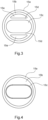
- the anti-torsion element 15 is a ring, described in more detail on the Figures 3 and 4 .
- the anti-torsion element 15 is a ring which comprises two joined cylindrical sections of the same axis formed in one piece, a first section 15a of larger diameter intended, once mounted in the plug 1, to be turned towards the head 3, and a second section 15b, of smaller diameter, intended to be turned towards the cables 4a and 4b once mounted in plug 1.
- a shoulder 2b is formed inside the body 2, such that the diameter of the section 15a corresponds to the internal diameter of the body 2 before the shoulder and the diameter of the section 15b corresponds to the internal diameter of the body 2 after the shoulder, forming a shoulder 15f on the outer surface of the ring 15 between the sections 15a and 15b.
- the body 2 in which the ring 15 is inserted is placed on the cables 4a and 4b before the assembly of the head 3 on the body as indicated above.
- a flange 15c of substantially oblong shape, consisting of two semicircles joined by straight lines, is formed in the second section 15b by two parallel cords 15d, the flange 15c having a width corresponding substantially to twice the section of a cable and a height corresponding substantially to the diameter of a cable in order to wedge the two cables 4a, 4b joined in the flange 15c.
- the ring 15 thus guarantees that the cables 4a, 4b will not move in relation to to the head 3.
- soldering/connecting the cables 4a, 4b are envisaged within the scope of the present invention.
- the slots 15e formed in the second section 15b between the strings 15d and the periphery of the second section 15b allow material savings.
- the shape of the flange 15 in the figures is not intended to limit the scope of the invention. Any cross-sectional shape capable of maintaining the two cables joined together is envisaged within the scope of the present invention. Thus a rectangular shape is envisaged within the scope of the present invention. It is also not necessary for the strings 15d to be complete: lugs projecting in the direction of the strings 15d but not meeting are also envisaged within the scope of the present invention.
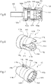
- the audio plug 101 comprises a body 102, the sheath 105 and the ring 115.
- the body 102 carries on its external face a groove 102c, serving to improve the gripping of the body 102, whether for the operations of mounting the audio plug 101 or for gripping the audio plug 101 once mounted.
- a groove 102c serving to improve the gripping of the body 102, whether for the operations of mounting the audio plug 101 or for gripping the audio plug 101 once mounted.
- other surface patterns can however be envisaged instead of the groove 102c, such as for example the formation of a surface effect of the knurling type (knurling in English), always with the aim to create friction with the fingers for a better grip.
- the body 102 comprises a shoulder 102b formed on the internal surface of the body 102 to form two cylindrical sections in the body 102, a first cylindrical section 102d on the sleeve 105 side and a second cylindrical section 102e on the downstream side (cables) of smaller diameter than the first cylindrical section 102d on the upstream side.
- a thread 102a is formed on the end of the body 102 on the sleeve 105 side to cooperate by screwing with the thread 105a formed behind the collar 105b formed on the sleeve 105.
- the internal surface of the body 102 in the internal section of smaller diameter 102e, comprises a first part of fixed diameter 102f and a second part 102g of diameter tightening up to the end on the cable side, the internal surface of the body 102 keeping a symmetry of revolution around its longitudinal axis (from left to right on the Figure 5 ).
- Two openings 115i formed on the side surface of part 115h of ring 115 form two jaws 115j, so that when body 102 is screwed onto sleeve 105, with ring 115 inserted into body 102, the internal wall of the part 102e of the body 102 presses lightly on the jaws 115j to tighten them on the cables and thus hold them better.
- this part of the ring could have more openings, to form at this end of the ring a deformable part tightening around the cables under the effect of the tapered part 102g of the internal wall of the body 102.
- Claws 115k can be formed in the jaws 115j to hold the cables even better, increasing the friction with the cables.
- a single claw 115k transverse to the direction of the cables has been represented in the jaws 115j, it is understood that other types of claws are possible.
- any surface increasing the friction for example a textured surface, several parallel transverse claws, discontinuous claws, are possible.
- the claws 115k face each other on the two jaws 115j, but they could also be offset from each other, or be in different numbers and positions on each jaw 115j, without depart from the scope of the present invention.
- a substantially oblong-shaped opening 115c is formed in the part 115b of the ring 115, again to hold the cables once the audio plug 101 has been fitted, the effect of holding the cables being accentuated in the second embodiment by the tightening obtained by the jaws 115j which frame the shape oblong 115c and by claws 115k.
- ribs 115l are formed in the direction of the depth of the ring 115 in the inner surface of the first large diameter part 115a of the ring 115, to save material.
- the ring 15 is preferably made of plastic material, for example polyethylene (PE), polypropylene (PP), polyvinyl chloride (PVC), polycarbonate (PC), nylon, injection molded in one piece. Other materials such as Teflon (registered trademark), metal, in particular aluminum, can also however be envisaged to form the ring 15.
- the body 2 is preferably made of metal (copper, steel, bronze, aluminum) , machined or injection molded in one piece. Other materials, such as plastic materials, can however also be envisaged to form the body 2.
- a ring according to the invention can be adapted to any type of plug on which at least two cables can be connected.
Landscapes
- Details Of Connecting Devices For Male And Female Coupling (AREA)
Applications Claiming Priority (1)
| Application Number | Priority Date | Filing Date | Title |
|---|---|---|---|
| FR2109359A FR3126807B1 (fr) | 2021-09-07 | 2021-09-07 | Fiche audio |
Publications (1)
| Publication Number | Publication Date |
|---|---|
| EP4145644A1 true EP4145644A1 (de) | 2023-03-08 |
Family
ID=78332900
Family Applications (1)
| Application Number | Title | Priority Date | Filing Date |
|---|---|---|---|
| EP22193511.7A Pending EP4145644A1 (de) | 2021-09-07 | 2022-09-01 | Audiostecker |
Country Status (4)
| Country | Link |
|---|---|
| US (1) | US20230075477A1 (de) |
| EP (1) | EP4145644A1 (de) |
| CN (1) | CN115776016A (de) |
| FR (1) | FR3126807B1 (de) |
Citations (3)
| Publication number | Priority date | Publication date | Assignee | Title |
|---|---|---|---|---|
| US20140168528A1 (en) * | 2009-03-12 | 2014-06-19 | Samsung Electronics Co., Ltd. | Signal transfer apparatus |
| US20170004907A1 (en) * | 2015-07-02 | 2017-01-05 | Sumitomo Electric Industries, Ltd. | Multi-core cable |
| CN209766700U (zh) * | 2019-04-30 | 2019-12-10 | 吴丰廷 | 音讯接头及音讯传输装置 |
-
2021
- 2021-09-07 FR FR2109359A patent/FR3126807B1/fr active Active
-
2022
- 2022-09-01 EP EP22193511.7A patent/EP4145644A1/de active Pending
- 2022-09-05 CN CN202211078995.4A patent/CN115776016A/zh active Pending
- 2022-09-06 US US17/903,162 patent/US20230075477A1/en active Pending
Patent Citations (3)
| Publication number | Priority date | Publication date | Assignee | Title |
|---|---|---|---|---|
| US20140168528A1 (en) * | 2009-03-12 | 2014-06-19 | Samsung Electronics Co., Ltd. | Signal transfer apparatus |
| US20170004907A1 (en) * | 2015-07-02 | 2017-01-05 | Sumitomo Electric Industries, Ltd. | Multi-core cable |
| CN209766700U (zh) * | 2019-04-30 | 2019-12-10 | 吴丰廷 | 音讯接头及音讯传输装置 |
Also Published As
| Publication number | Publication date |
|---|---|
| US20230075477A1 (en) | 2023-03-09 |
| FR3126807B1 (fr) | 2023-07-21 |
| CN115776016A (zh) | 2023-03-10 |
| FR3126807A1 (fr) | 2023-03-10 |
Similar Documents
| Publication | Publication Date | Title |
|---|---|---|
| FR2658109A1 (fr) | Dispositif pour assurer l'application d'un couple de rotation predetermine lors du serrage d'une vis ou element similaire. | |
| EP0340075A1 (de) | Abzweigklemme zur Verbindung einer isolierten Freileitung mit einer isolierten Abzweigleitung | |
| FR2763437A1 (fr) | Dispositif d'entree de cable | |
| EP2375502B1 (de) | Einspannvorrichtung mit teilbarem Kopf für elektrischen Anschlussschaft | |
| EP4145644A1 (de) | Audiostecker | |
| EP1198684A1 (de) | Schutzkappe für ein rohrende | |
| EP0911915B1 (de) | Elektrische Anschlussklemme und Endstück einer Leuchtstoffröhre mit einer solchen Klemme | |
| EP2998208B1 (de) | Vorrichtung zur befestigung einer schutzummantelung einer hand auf dem griff des lenkers eines motorrads | |
| FR2653202A1 (fr) | Raccord pour tuyau d'evacuation des eaux residuaires des appareils sanitaires. | |
| EP0410843B1 (de) | Verbindungsstück für Kunststoffrohre und Montageverfahren | |
| EP0172779B1 (de) | Mehrpoliger elektrischer Verbinder | |
| FR3065498B1 (fr) | Systeme de vis a tete secable et procede de fabrication d'un tel systeme | |
| EP0581678B1 (de) | Schlauch mit radialer Spannvorrichtung zum Verbinden mit einem Rohrende; Schlauchverbindung mit diesem Schlauch | |
| EP0902997A1 (de) | Vorrichtung zum montieren wenigstens eines kabels in eine scheibe,welche zum positionieren in eine schutzmuffe einer kabelverbindung bestimmt ist | |
| EP1378975B1 (de) | In einem Sachlloch einsetzbare elektrische Verbindungseinrichtung | |
| EP0232633A1 (de) | Vorrichtung zum Befestigen einer Kupplungshülse am Ende eines Seiles | |
| FR2627640A1 (fr) | Connecteur electrique multiple | |
| FR2784247A1 (fr) | Enveloppe, en particulier coffret, a fond presentant au moins un trou obture par un bouchon, notamment pour materiel electrique | |
| FR2895583A1 (fr) | Dispositif d'enserrement etanche d'au moins un cable electrique | |
| FR2629896A3 (fr) | Raccord rapide pour tube | |
| FR2597168A1 (fr) | Collier de serrage, notamment pour tube, cable ou autre conduit | |
| EP0648945A2 (de) | Gewindebefestigung | |
| FR2632458A1 (fr) | Connecteur electrique | |
| FR2852659A1 (fr) | Raccord a compression | |
| FR2510311A1 (fr) | Raccord de prise de courant sur cable electrique |
Legal Events
| Date | Code | Title | Description |
|---|---|---|---|
| PUAI | Public reference made under article 153(3) epc to a published international application that has entered the european phase |
Free format text: ORIGINAL CODE: 0009012 |
|
| STAA | Information on the status of an ep patent application or granted ep patent |
Free format text: STATUS: THE APPLICATION HAS BEEN PUBLISHED |
|
| AK | Designated contracting states |
Kind code of ref document: A1 Designated state(s): AL AT BE BG CH CY CZ DE DK EE ES FI FR GB GR HR HU IE IS IT LI LT LU LV MC MK MT NL NO PL PT RO RS SE SI SK SM TR |
|
| STAA | Information on the status of an ep patent application or granted ep patent |
Free format text: STATUS: REQUEST FOR EXAMINATION WAS MADE |
|
| 17P | Request for examination filed |
Effective date: 20230908 |
|
| RBV | Designated contracting states (corrected) |
Designated state(s): AL AT BE BG CH CY CZ DE DK EE ES FI FR GB GR HR HU IE IS IT LI LT LU LV MC MK MT NL NO PL PT RO RS SE SI SK SM TR |
|
| GRAP | Despatch of communication of intention to grant a patent |
Free format text: ORIGINAL CODE: EPIDOSNIGR1 |
|
| STAA | Information on the status of an ep patent application or granted ep patent |
Free format text: STATUS: GRANT OF PATENT IS INTENDED |
|
| RIC1 | Information provided on ipc code assigned before grant |
Ipc: H01R 11/11 20060101ALN20231218BHEP Ipc: H01R 4/02 20060101ALN20231218BHEP Ipc: H01R 24/58 20110101ALI20231218BHEP Ipc: H01R 13/58 20060101ALI20231218BHEP Ipc: H01R 13/56 20060101AFI20231218BHEP |
|
| INTG | Intention to grant announced |
Effective date: 20240110 |
|
| GRAS | Grant fee paid |
Free format text: ORIGINAL CODE: EPIDOSNIGR3 |
|
| GRAA | (expected) grant |
Free format text: ORIGINAL CODE: 0009210 |
|
| STAA | Information on the status of an ep patent application or granted ep patent |
Free format text: STATUS: THE PATENT HAS BEEN GRANTED |