EP4145429A1 - Anzeigesystem, anzeigevorrichtung und anzeigeverbindungsmodul dafür - Google Patents
Anzeigesystem, anzeigevorrichtung und anzeigeverbindungsmodul dafür Download PDFInfo
- Publication number
- EP4145429A1 EP4145429A1 EP22180451.1A EP22180451A EP4145429A1 EP 4145429 A1 EP4145429 A1 EP 4145429A1 EP 22180451 A EP22180451 A EP 22180451A EP 4145429 A1 EP4145429 A1 EP 4145429A1
- Authority
- EP
- European Patent Office
- Prior art keywords
- device housing
- connector
- knob
- display
- block
- Prior art date
- Legal status (The legal status is an assumption and is not a legal conclusion. Google has not performed a legal analysis and makes no representation as to the accuracy of the status listed.)
- Granted
Links
Images


Classifications
-
- F—MECHANICAL ENGINEERING; LIGHTING; HEATING; WEAPONS; BLASTING
- F16—ENGINEERING ELEMENTS AND UNITS; GENERAL MEASURES FOR PRODUCING AND MAINTAINING EFFECTIVE FUNCTIONING OF MACHINES OR INSTALLATIONS; THERMAL INSULATION IN GENERAL
- F16M—FRAMES, CASINGS OR BEDS OF ENGINES, MACHINES OR APPARATUS, NOT SPECIFIC TO ENGINES, MACHINES OR APPARATUS PROVIDED FOR ELSEWHERE; STANDS; SUPPORTS
- F16M11/00—Stands or trestles as supports for apparatus or articles placed thereon ; Stands for scientific apparatus such as gravitational force meters
- F16M11/02—Heads
- F16M11/04—Means for attachment of apparatus; Means allowing adjustment of the apparatus relatively to the stand
- F16M11/041—Allowing quick release of the apparatus
-
- H—ELECTRICITY
- H05—ELECTRIC TECHNIQUES NOT OTHERWISE PROVIDED FOR
- H05K—PRINTED CIRCUITS; CASINGS OR CONSTRUCTIONAL DETAILS OF ELECTRIC APPARATUS; MANUFACTURE OF ASSEMBLAGES OF ELECTRICAL COMPONENTS
- H05K5/00—Casings, cabinets or drawers for electric apparatus
- H05K5/30—Side-by-side or stacked arrangements
-
- F—MECHANICAL ENGINEERING; LIGHTING; HEATING; WEAPONS; BLASTING
- F16—ENGINEERING ELEMENTS AND UNITS; GENERAL MEASURES FOR PRODUCING AND MAINTAINING EFFECTIVE FUNCTIONING OF MACHINES OR INSTALLATIONS; THERMAL INSULATION IN GENERAL
- F16M—FRAMES, CASINGS OR BEDS OF ENGINES, MACHINES OR APPARATUS, NOT SPECIFIC TO ENGINES, MACHINES OR APPARATUS PROVIDED FOR ELSEWHERE; STANDS; SUPPORTS
- F16M11/00—Stands or trestles as supports for apparatus or articles placed thereon ; Stands for scientific apparatus such as gravitational force meters
- F16M11/20—Undercarriages with or without wheels
- F16M11/22—Undercarriages with or without wheels with approximately constant height, e.g. with constant length of column or of legs
-
- F—MECHANICAL ENGINEERING; LIGHTING; HEATING; WEAPONS; BLASTING
- F16—ENGINEERING ELEMENTS AND UNITS; GENERAL MEASURES FOR PRODUCING AND MAINTAINING EFFECTIVE FUNCTIONING OF MACHINES OR INSTALLATIONS; THERMAL INSULATION IN GENERAL
- F16M—FRAMES, CASINGS OR BEDS OF ENGINES, MACHINES OR APPARATUS, NOT SPECIFIC TO ENGINES, MACHINES OR APPARATUS PROVIDED FOR ELSEWHERE; STANDS; SUPPORTS
- F16M13/00—Other supports for positioning apparatus or articles; Means for steadying hand-held apparatus or articles
- F16M13/02—Other supports for positioning apparatus or articles; Means for steadying hand-held apparatus or articles for supporting on, or attaching to, an object, e.g. tree, gate, window-frame, cycle
-
- G—PHYSICS
- G09—EDUCATION; CRYPTOGRAPHY; DISPLAY; ADVERTISING; SEALS
- G09F—DISPLAYING; ADVERTISING; SIGNS; LABELS OR NAME-PLATES; SEALS
- G09F9/00—Indicating arrangements for variable information in which the information is built-up on a support by selection or combination of individual elements
- G09F9/30—Indicating arrangements for variable information in which the information is built-up on a support by selection or combination of individual elements in which the desired character or characters are formed by combining individual elements
- G09F9/302—Indicating arrangements for variable information in which the information is built-up on a support by selection or combination of individual elements in which the desired character or characters are formed by combining individual elements characterised by the form or geometrical disposition of the individual elements
- G09F9/3026—Video wall, i.e. stackable semiconductor matrix display modules
-
- H—ELECTRICITY
- H05—ELECTRIC TECHNIQUES NOT OTHERWISE PROVIDED FOR
- H05K—PRINTED CIRCUITS; CASINGS OR CONSTRUCTIONAL DETAILS OF ELECTRIC APPARATUS; MANUFACTURE OF ASSEMBLAGES OF ELECTRICAL COMPONENTS
- H05K5/00—Casings, cabinets or drawers for electric apparatus
- H05K5/0017—Casings, cabinets or drawers for electric apparatus with operator interface units
-
- H—ELECTRICITY
- H05—ELECTRIC TECHNIQUES NOT OTHERWISE PROVIDED FOR
- H05K—PRINTED CIRCUITS; CASINGS OR CONSTRUCTIONAL DETAILS OF ELECTRIC APPARATUS; MANUFACTURE OF ASSEMBLAGES OF ELECTRICAL COMPONENTS
- H05K5/00—Casings, cabinets or drawers for electric apparatus
- H05K5/02—Details
- H05K5/0217—Mechanical details of casings
- H05K5/0221—Locks; Latches
-
- F—MECHANICAL ENGINEERING; LIGHTING; HEATING; WEAPONS; BLASTING
- F16—ENGINEERING ELEMENTS AND UNITS; GENERAL MEASURES FOR PRODUCING AND MAINTAINING EFFECTIVE FUNCTIONING OF MACHINES OR INSTALLATIONS; THERMAL INSULATION IN GENERAL
- F16M—FRAMES, CASINGS OR BEDS OF ENGINES, MACHINES OR APPARATUS, NOT SPECIFIC TO ENGINES, MACHINES OR APPARATUS PROVIDED FOR ELSEWHERE; STANDS; SUPPORTS
- F16M2200/00—Details of stands or supports
- F16M2200/02—Locking means
- F16M2200/021—Locking means for rotational movement
- F16M2200/024—Locking means for rotational movement by positive interaction, e.g. male-female connections
-
- F—MECHANICAL ENGINEERING; LIGHTING; HEATING; WEAPONS; BLASTING
- F16—ENGINEERING ELEMENTS AND UNITS; GENERAL MEASURES FOR PRODUCING AND MAINTAINING EFFECTIVE FUNCTIONING OF MACHINES OR INSTALLATIONS; THERMAL INSULATION IN GENERAL
- F16M—FRAMES, CASINGS OR BEDS OF ENGINES, MACHINES OR APPARATUS, NOT SPECIFIC TO ENGINES, MACHINES OR APPARATUS PROVIDED FOR ELSEWHERE; STANDS; SUPPORTS
- F16M2200/00—Details of stands or supports
- F16M2200/02—Locking means
- F16M2200/025—Locking means for translational movement
- F16M2200/028—Locking means for translational movement by positive interaction, e.g. male-female connections
Definitions
- the present invention relates to a display device, and in particular to a display device of a display system which includes a plurality of display devices.
- a display system may include a plurality of display devices arranged in a matrix. Such a display system may be utilized to display huge images.
- the display devices are connected to each other with latches or bolts.
- connecting the display devices using latches or bolts requires time and effort, and the costs of mounting and maintaining them are thus increased. For example, when one display device in the center portion of the display system is damaged, the non-damaged display devices in the same column or the same row must all be removed just to repair the single damaged display device. The repair process is complex.
- Embodiments of the invention are provided to address the aforementioned difficulty.
- a display device in one embodiment, includes a device housing, a knob, a restriction unit and a screen panel.
- the knob is rotatably connected to the device housing, wherein the knob comprises a latch and a plurality of teeth, the knob is adapted to be rotated between a first knob location and a second knob location, and when the knob is in the first knob location, the latch protrudes from the device housing, and when the knob is in the second knob location, the latch is received in the device housing.
- the restriction unit is disposed in the device housing, wherein the restriction unit is adapted to be connected to one of the teeth to restrict the knob.
- the screen panel is detachably connected to the device housing.
- the teeth are ratchet teeth.
- the restriction unit comprises a restriction block and a spring, one end of the spring abuts the device housing, the other end of the spring abuts the restriction block, the restriction block is adapted to be moved between a first block position and a second block position, and when the restriction block is in the first block position, the restriction block is wedged against at least one of the teeth, and when the restriction block is in the second block position, the restriction block releases the knob.
- the display device further comprises a first connector, wherein the first connector is slidably connected to the device housing, the first connector is adapted to be moved between a first connector position and a second connector position, and when the first connector is in the first connector position, the first connector protrudes from the device housing, and when the first connector is in the second connector position, the first connector is received in the device housing.
- the display device further comprises a locking member and a cover piece, wherein the cover piece is connected to the device housing, the locking member pivots on the first connecter, and in a first locking state, the locking member is connected to the cover piece to restrict the movement of the first connector relative to the device housing.
- the cover piece comprises a first slot and a second slot, and when the first connector is in the first connector position, the locking member is adapted to be connected to the first slot, and when the first connector is in the second connector position, the locking member is adapted to be connected to the second slot.
- the display device further comprises a hook and two bolts, wherein the hook comprises a holding portion, the device comprises a first L-shaped groove and two second L-shaped grooves, the bolts pass through the second L-shaped grooves to connect the hook to the device housing, and the holding portion passes through the first L-shaped groove.
- the bolts in an affixed state, affix the position of the hook relative to the device housing, and in a released state, the bolts are adapted to be moved along the second L-shaped grooves, and the holding portion is adapted to be moved along the first L-shaped groove.
- the display device further comprises a plurality of panel magnets and a plurality of connection magnets, wherein the panel magnets are disposed on the screen panel, the connection magnets are disposed on the device housing, the panel magnets are adapted to be attracted by the connection magnets, and the screen panel is detachably connected to the device housing.
- the display device further comprises a plurality of fine-tuning screws
- the device housing further comprises a plurality of screw holders, the fine-tuning screws are connected to the screw holders, the connection magnets are disposed on the fine-tuning screws, and the position of the connection magnets relative to the device housing can be modified by rotating the fine-tuning screws.
- the screen panel comprises at least one panel buckling portion
- the device housing comprises at least one housing buckling portion
- the housing buckling portion is adapted to connect to the panel buckling portion to support the screen panel.
- the display device further comprises a riser card and a second connector, wherein the riser card is slidably connected to the device housing, the second connector is disposed on the riser card, and the second connector is adapted to be connected to the screen panel.
- a display system in another embodiment, includes at least one bracket and a plurality of display devices.
- the display devices are hung on the bracket.
- Each display device comprises a device housing, a knob, a restriction unit and a screen panel.
- the knob is rotatably connected to the device housing, wherein the knob comprises a latch and a plurality of teeth, the knob is adapted to be rotated between a first knob location and a second knob location, and when the knob is in the first knob location, the latch protrudes from the device housing, and when the knob is in the second knob location, the latch is received in the device housing.
- the restriction unit is disposed in the device housing, wherein the restriction unit is adapted to be connected to one of the teeth to restrict the knob.
- the screen panel is detachably connected to the device housing. The knob is adapted to connect the adjacent two display devices.
- a display connection module in further another embodiment, includes a device housing, a knob and a restriction unit.
- the knob is rotatably connected to the device housing, wherein the knob comprises a latch and a plurality of teeth, the knob is adapted to be rotated between a first knob location and a second knob location, and when the knob is in the first knob location, the latch protrudes from the device housing, and when the knob is in the second knob location, the latch is received in the device housing.
- the restriction unit is disposed in the device housing, wherein the restriction unit is adapted to be connected to one of the teeth to restrict the knob.
- the maintainer can detach the damaged display device through the following steps. First, the screen panel is removed from the device housing. Then, the bolts on the hook are released. The hook is pushed to be separated from the bracket. Next, the first connector is pushed to the second connector position, and the knob is rotated to the second knob location. Finally, the device housing can be detached directly.
- the display devices of the embodiment of the invention can be easily assembled and disassembled. Particularly, when the damaged display device is located in the center portion of the display system, the damaged display device can be detached without removing the non-damaged display devices in the same column or the same row. The maintenance procedure is simplified. Additionally, the knob can tightly and seamlessly connect the two adjacent display devices.
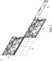
- Fig. 1 shows a display system of an embodiment of the invention.
- the display system T of the embodiment of the invention includes a plurality of display devices (D, D').
- the display devices (D, D') can be electrically connected to each other to provide a large-size image.
- the display devices (D, D') are hung on a bracket B.
- the display device D is completely presented, and a portion of the elements (for example, screen panel) of the display device D' is omitted.
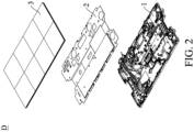
- Fig. 2 is an exploded view of the display device of the embodiment of the invention.
- the display device D of the embodiment of the invention includes a device housing 1, a cover piece 2 and a screen panel 3.
- the cover piece 2 is connected to the device housing 1.
- the screen panel 3 is disposed on the cover piece 2.
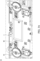
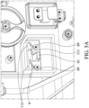
- Fig. 3A shows a knob of the embodiment of the invention.
- Fig. 3B shows the details of the knob of the embodiment of the invention.
- the display device D of the embodiment of the invention further comprises a knob 41 and a restriction unit 42.
- the knob 41 is rotatably connected to the device housing 1.
- the knob 41 comprises a latch 411 and a plurality of teeth 412.
- the knob 41 is adapted to be rotated between a first knob location and a second knob location.
- the latch 411 protrudes from the device housing 1.
- the knob 41 is in the second knob location, the latch 411 is received in the device housing 1.
- the restriction unit 42 is disposed in the device housing 1.
- the restriction unit 42 is adapted to be connected to one of the teeth 412 to restrict the knob 41.
- the teeth 412 are ratchet teeth, which provide a non-return function.
- the disclosure is not meant to restrict the invention.
- the shape of the teeth 412 can be modified.
- the restriction unit 42 comprises a restriction block 421 and a spring 422.
- One end of the spring 422 abuts the device housing 1.
- the other end of the spring 422 abuts the restriction block 421.
- the restriction block 421 is adapted to be moved between a first block position and a second block position. When the restriction block 421 is in the first block position ( Figs. 3A and 3B ), the restriction block 421 is wedged against at least one of the teeth 412 to provide the non-return function. When the restriction block 421 is in the second block position, the restriction block 421 releases the knob 41.
- the latch 411 is adapted to be connected to the device housing 1' of another display device D'.
- the display device D' comprises a rubber gasket 19.
- the latch 411 abuts the rubber gasket 19.
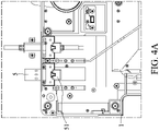
- Figs. 4A and 4B show a first connector of the display device of the embodiment of the invention.
- the display device D further comprises a first connector 5.
- the first connector 5 is slidably connected to the device housing 1.
- the first connector 5 is adapted to be moved between a first connector position and a second connector position.
- the first connector 5 protrudes from the device housing 1.
- the first connector 5 is received in the device housing 1.
- the first connector 5 can be a power connector or a USB connector.
- the display device further comprises a locking member 51.
- the locking member 51 pivots on the first connecter 5. In a first locking state, the locking member 51 is connected to the cover piece 2 to restrict the movement of the first connector 5 relative to the device housing 1.
- the cover piece 2 comprises a first slot 211 and a second slot 212.
- the locking member 51 is adapted to be connected to the first slot 211.
- the locking member 51 is adapted to be connected to the second slot 212.
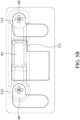
- Figs. 5A and 5B show a hook of the embodiment of the invention.
- the display device further comprises a hook 6 and two bolts 69.
- the hook 6 comprises a holding portion 61.
- the device 1 comprises a first L-shaped groove 111 and two second L-shaped grooves 112.
- the bolts 69 pass through the second L-shaped grooves 112 to connect the hook 6 to the device housing 1.
- the holding portion 61 passes through the first L-shaped groove 111.
- the bolts 69 are affixed to fasten the position of the hook 6 relative to the device housing 1.
- the bolts 69 are released and adapted to be moved along the second L-shaped grooves 112, and the holding portion 61 is adapted to be moved along the first L-shaped groove 111.
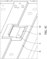
- Fig. 5C shows the hook of the embodiment of the invention connected to the bracket.
- the hook 6 comprises a hook connecting portion 62.
- the hook 6 is hung on the bracket B via the hook connecting portion 62.
- the bracket B comprises a bracket connecting portion B1.
- the hook connecting portion 62 is connected to the bracket connecting portion B1. In the released state, the hook 6 can be moved, and the hook connecting portion 62 is separated from the bracket connecting portion B1.
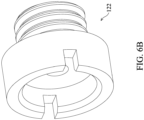
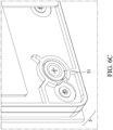
- Figs. 6A and 6B show fine-tuning screws of the embodiment of the invention.
- Fig. 6C shows a panel magnet of the embodiment of the invention.
- the display device further comprises a plurality of panel magnets 31 and a plurality of connection magnets 121.
- the panel magnets 31 are disposed on the screen panel 3.
- the connection magnets 121 are disposed on the device housing 1.
- the panel magnets 31 are adapted to be attracted by the connection magnets 121, and the screen panel 3 is thus detachably connected to the device housing 1.
- the display device further comprises a plurality of fine-tuning screws 122.
- the device housing further comprises a plurality of screw holders 123.
- the fine-tuning screws 122 are connected to the screw holders 123.
- the connection magnets 121 are disposed on the fine-tuning screws 122. The position of the connection magnets 121 relative to the device housing 1 can be modified by rotating the fine-tuning screws 122.
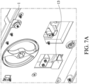
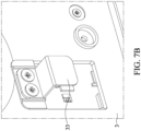
- Figs. 7A and 7B show a panel buckling portion and a housing buckling portion of the embodiment of the invention.
- the screen panel 3 comprises at least one panel buckling portion 33.
- the device housing 1 comprises at least one housing buckling portion 13.
- the housing buckling portion 13 is adapted to connect to the panel buckling portion 33 to support the screen panel 3.
- Figs. 8A and 8B show a riser card of the embodiment of the invention.
- the display device further comprises a riser card 7 and a second connector 79.
- the riser card 7 is slidably connected to the device housing 1.
- the second connector 79 is disposed on the riser card 7.
- the second connector 79 is adapted to be connected to the screen panel 3.
- the riser card 7 comprises a plurality of openings 71. A gap is formed between the inner wall of the opening 71 and a screw 17. The riser card 7 thus can be slid relative to the device housing 1 to prevent the second connector 79 being damaged during the screen panel 3 being detached.
- the maintainer can detach the damaged display device through the following steps.
- the screen panel 3 is removed from the device housing 1.
- the bolts 69 on the hook 6 are released.
- the hook 9 is pushed to be separated from the bracket B.
- the first connector 5 is pushed to the second connector position, and the knob 41 is rotated to the second knob location.
- the device housing 1 can be detached directly.
- the display devices of the embodiment of the invention can be easily assembled and disassembled.
- the damaged display device when the damaged display device is located in the center portion of the display system T, the damaged display device can be detached without removing the non-damaged display devices in the same column or the same row.
- the maintenance procedure is simplified. Additionally, the knob 41 can tightly and seamlessly connect the two adjacent display devices.
Landscapes
- Engineering & Computer Science (AREA)
- General Engineering & Computer Science (AREA)
- Microelectronics & Electronic Packaging (AREA)
- Mechanical Engineering (AREA)
- Devices For Indicating Variable Information By Combining Individual Elements (AREA)
- Multimedia (AREA)
- Physics & Mathematics (AREA)
- General Physics & Mathematics (AREA)
- Theoretical Computer Science (AREA)
Applications Claiming Priority (3)
| Application Number | Priority Date | Filing Date | Title |
|---|---|---|---|
| US202163241079P | 2021-09-06 | 2021-09-06 | |
| US202163241570P | 2021-09-08 | 2021-09-08 | |
| TW111100382A TWI845882B (zh) | 2021-09-06 | 2022-01-05 | 顯示系統、顯示器裝置及其顯示器連接裝置 |
Publications (3)
| Publication Number | Publication Date |
|---|---|
| EP4145429A1 true EP4145429A1 (de) | 2023-03-08 |
| EP4145429B1 EP4145429B1 (de) | 2025-09-17 |
| EP4145429C0 EP4145429C0 (de) | 2025-09-17 |
Family
ID=82214432
Family Applications (1)
| Application Number | Title | Priority Date | Filing Date |
|---|---|---|---|
| EP22180451.1A Active EP4145429B1 (de) | 2021-09-06 | 2022-06-22 | Anzeigesystem, anzeigevorrichtung und anzeigeverbindungsmodul dafür |
Country Status (4)
| Country | Link |
|---|---|
| US (1) | US11889637B2 (de) |
| EP (1) | EP4145429B1 (de) |
| JP (1) | JP7431283B2 (de) |
| CN (1) | CN115775488B (de) |
Citations (2)
| Publication number | Priority date | Publication date | Assignee | Title |
|---|---|---|---|---|
| EP3054369A1 (de) * | 2015-02-09 | 2016-08-10 | Samsung Electronics Co., Ltd. | Anzeigemodul und anzeigevorrichtung damit |
| WO2017123528A1 (en) * | 2016-01-12 | 2017-07-20 | Southco, Inc. | Panel attachment latch |
Family Cites Families (17)
| Publication number | Priority date | Publication date | Assignee | Title |
|---|---|---|---|---|
| CN103021284B (zh) | 2012-12-03 | 2016-01-06 | 深圳市立翔慧科光电科技有限公司 | 一种led组合屏锁扣机构、led单元屏和led组合屏 |
| CN103544898B (zh) | 2013-11-05 | 2015-05-13 | 吴小刚 | 一种led显示屏的拼接固定锁 |
| CN103671378B (zh) | 2013-12-24 | 2016-03-02 | 广东威创视讯科技股份有限公司 | 一种显示屏箱体锁紧机构 |
| JP2015210429A (ja) | 2014-04-28 | 2015-11-24 | パナソニック株式会社 | マルチディスプレイシステム |
| CN203982709U (zh) | 2014-06-06 | 2014-12-03 | 深圳市奥蕾达科技有限公司 | 显示屏收容箱及其拼接箱体 |
| CN104537952B (zh) * | 2014-12-18 | 2017-01-25 | 苏州佳世达电通有限公司 | 显示器及拼接显示装置 |
| CN104902716B (zh) | 2015-06-19 | 2017-07-14 | 潘尚法 | 一种带约束滑槽的锁扣、led箱体和led显示屏 |
| GB201620544D0 (en) * | 2016-12-02 | 2017-01-18 | Barco Nv | Front maintenance apparatus for flexible tiled LED display |
| CN107195254B (zh) | 2017-07-26 | 2023-05-12 | 深圳市联建光电股份有限公司 | 一种模块化的大型触控显示屏 |
| EP3499052B1 (de) * | 2017-12-15 | 2021-11-17 | LG Display Co., Ltd. | Gekachelte anzeigevorrichtung und kachelvorrichtung dafür |
| US11353732B2 (en) * | 2018-08-24 | 2022-06-07 | Samsung Electronics Co., Ltd. | Display apparatus |
| CN108986679A (zh) | 2018-09-21 | 2018-12-11 | 惠州市艾比森光电有限公司 | 显示模组拼接结构及显示屏 |
| KR102609374B1 (ko) * | 2018-11-28 | 2023-12-04 | 삼성전자주식회사 | 디스플레이 장치 |
| KR102593329B1 (ko) * | 2018-12-20 | 2023-10-25 | 엘지디스플레이 주식회사 | 멀티디스플레이의 갭 조절장치 및 이를 포함하는 멀티디스플레이 |
| CN211646633U (zh) * | 2019-11-27 | 2020-10-09 | 泮永庆 | 一种市政给排水管连接件 |
| CN211062392U (zh) * | 2020-02-18 | 2020-07-21 | 济南天力恒达电子科技有限公司 | 一种可实现快速拼接的led显示屏 |
| CN212986669U (zh) * | 2020-06-30 | 2021-04-16 | 合肥山海达数据存储科技股份有限公司 | 一种用于ipfs数据展示的拼接式大屏 |
-
2022
- 2022-01-18 CN CN202210053132.5A patent/CN115775488B/zh active Active
- 2022-04-13 US US17/719,773 patent/US11889637B2/en active Active
- 2022-06-22 EP EP22180451.1A patent/EP4145429B1/de active Active
- 2022-06-27 JP JP2022102895A patent/JP7431283B2/ja active Active
Patent Citations (2)
| Publication number | Priority date | Publication date | Assignee | Title |
|---|---|---|---|---|
| EP3054369A1 (de) * | 2015-02-09 | 2016-08-10 | Samsung Electronics Co., Ltd. | Anzeigemodul und anzeigevorrichtung damit |
| WO2017123528A1 (en) * | 2016-01-12 | 2017-07-20 | Southco, Inc. | Panel attachment latch |
Also Published As
| Publication number | Publication date |
|---|---|
| EP4145429B1 (de) | 2025-09-17 |
| US20230072830A1 (en) | 2023-03-09 |
| EP4145429C0 (de) | 2025-09-17 |
| US11889637B2 (en) | 2024-01-30 |
| JP7431283B2 (ja) | 2024-02-14 |
| CN115775488A (zh) | 2023-03-10 |
| JP2023038157A (ja) | 2023-03-16 |
| CN115775488B (zh) | 2025-12-05 |
Similar Documents
| Publication | Publication Date | Title |
|---|---|---|
| CN110888491B (zh) | 具有用于桌面显示器的安全闩锁的磁性附接机构 | |
| US7161798B2 (en) | Expansion card retention apparatus | |
| CN1253771C (zh) | 具有可替换的液晶显示屏的计算机系统 | |
| CN109961696B (zh) | 多面板显示装置 | |
| US6138839A (en) | Pivoted latching bar for retaining expansion cards | |
| US6580603B1 (en) | Structure for mounting computer devices, pivotable between operating and service positions, including a pivoting support member | |
| CN103748869A (zh) | 支架、安装系统、模板纸、显示装置以及电视接收机 | |
| US6693800B1 (en) | Expansion card mounting apparatus | |
| US8385058B2 (en) | Display device and electric device | |
| CN1760795A (zh) | 计算装置的安装系统 | |
| EP4145429A1 (de) | Anzeigesystem, anzeigevorrichtung und anzeigeverbindungsmodul dafür | |
| US20190254189A1 (en) | Mounting apparatus for expansion cards, casing, and electronic device using the same | |
| CN1979328A (zh) | 数字微镜装置组件和使用该组件的光学投影系统 | |
| US7396235B2 (en) | Modular electronic device | |
| US7215537B1 (en) | Mounting system for electronic components | |
| CN111480189B (zh) | 显示设备 | |
| US20050111169A1 (en) | Mounting apparatus for power supply | |
| US6757163B2 (en) | Computer having an auxiliary memory unit removably fastened on a fixing bracket | |
| US7520655B2 (en) | Liquid crystal display module | |
| KR100609913B1 (ko) | 지지장치 및 이를 갖는 디스플레이장치 | |
| US10141029B2 (en) | Securing apparatus for data storage device | |
| CN218920516U (zh) | 外接摄像头支架、外接摄像模组以及显示系统 | |
| CN223898008U (zh) | 一种显示装置 | |
| CN208044284U (zh) | 投影仪 | |
| TW202312822A (zh) | 顯示系統、顯示器裝置及其顯示器連接裝置 |
Legal Events
| Date | Code | Title | Description |
|---|---|---|---|
| PUAI | Public reference made under article 153(3) epc to a published international application that has entered the european phase |
Free format text: ORIGINAL CODE: 0009012 |
|
| STAA | Information on the status of an ep patent application or granted ep patent |
Free format text: STATUS: THE APPLICATION HAS BEEN PUBLISHED |
|
| AK | Designated contracting states |
Kind code of ref document: A1 Designated state(s): AL AT BE BG CH CY CZ DE DK EE ES FI FR GB GR HR HU IE IS IT LI LT LU LV MC MK MT NL NO PL PT RO RS SE SI SK SM TR |
|
| STAA | Information on the status of an ep patent application or granted ep patent |
Free format text: STATUS: REQUEST FOR EXAMINATION WAS MADE |
|
| 17P | Request for examination filed |
Effective date: 20230323 |
|
| RBV | Designated contracting states (corrected) |
Designated state(s): AL AT BE BG CH CY CZ DE DK EE ES FI FR GB GR HR HU IE IS IT LI LT LU LV MC MK MT NL NO PL PT RO RS SE SI SK SM TR |
|
| STAA | Information on the status of an ep patent application or granted ep patent |
Free format text: STATUS: EXAMINATION IS IN PROGRESS |
|
| 17Q | First examination report despatched |
Effective date: 20240410 |
|
| GRAP | Despatch of communication of intention to grant a patent |
Free format text: ORIGINAL CODE: EPIDOSNIGR1 |
|
| STAA | Information on the status of an ep patent application or granted ep patent |
Free format text: STATUS: GRANT OF PATENT IS INTENDED |
|
| INTG | Intention to grant announced |
Effective date: 20250610 |
|
| GRAS | Grant fee paid |
Free format text: ORIGINAL CODE: EPIDOSNIGR3 |
|
| GRAA | (expected) grant |
Free format text: ORIGINAL CODE: 0009210 |
|
| STAA | Information on the status of an ep patent application or granted ep patent |
Free format text: STATUS: THE PATENT HAS BEEN GRANTED |
|
| AK | Designated contracting states |
Kind code of ref document: B1 Designated state(s): AL AT BE BG CH CY CZ DE DK EE ES FI FR GB GR HR HU IE IS IT LI LT LU LV MC MK MT NL NO PL PT RO RS SE SI SK SM TR |
|
| REG | Reference to a national code |
Ref country code: GB Ref legal event code: FG4D |
|
| REG | Reference to a national code |
Ref country code: CH Ref legal event code: EP |
|
| REG | Reference to a national code |
Ref country code: IE Ref legal event code: FG4D |
|
| REG | Reference to a national code |
Ref country code: DE Ref legal event code: R096 Ref document number: 602022021473 Country of ref document: DE |
|
| U01 | Request for unitary effect filed |
Effective date: 20251016 |
|
| U07 | Unitary effect registered |
Designated state(s): AT BE BG DE DK EE FI FR IT LT LU LV MT NL PT RO SE SI Effective date: 20251021 |
|
| PG25 | Lapsed in a contracting state [announced via postgrant information from national office to epo] |
Ref country code: NO Free format text: LAPSE BECAUSE OF FAILURE TO SUBMIT A TRANSLATION OF THE DESCRIPTION OR TO PAY THE FEE WITHIN THE PRESCRIBED TIME-LIMIT Effective date: 20251217 |
|
| PG25 | Lapsed in a contracting state [announced via postgrant information from national office to epo] |
Ref country code: HR Free format text: LAPSE BECAUSE OF FAILURE TO SUBMIT A TRANSLATION OF THE DESCRIPTION OR TO PAY THE FEE WITHIN THE PRESCRIBED TIME-LIMIT Effective date: 20250917 |
|
| PG25 | Lapsed in a contracting state [announced via postgrant information from national office to epo] |
Ref country code: GR Free format text: LAPSE BECAUSE OF FAILURE TO SUBMIT A TRANSLATION OF THE DESCRIPTION OR TO PAY THE FEE WITHIN THE PRESCRIBED TIME-LIMIT Effective date: 20251218 |
|
| PG25 | Lapsed in a contracting state [announced via postgrant information from national office to epo] |
Ref country code: RS Free format text: LAPSE BECAUSE OF FAILURE TO SUBMIT A TRANSLATION OF THE DESCRIPTION OR TO PAY THE FEE WITHIN THE PRESCRIBED TIME-LIMIT Effective date: 20251217 |