EP4145417B1 - Betriebsanalyse von ansaugrauchmeldern - Google Patents
Betriebsanalyse von ansaugrauchmeldern Download PDFInfo
- Publication number
- EP4145417B1 EP4145417B1 EP22191553.1A EP22191553A EP4145417B1 EP 4145417 B1 EP4145417 B1 EP 4145417B1 EP 22191553 A EP22191553 A EP 22191553A EP 4145417 B1 EP4145417 B1 EP 4145417B1
- Authority
- EP
- European Patent Office
- Prior art keywords
- smoke detector
- detector device
- aspirating smoke
- user interface
- aspirating
- Prior art date
- Legal status (The legal status is an assumption and is not a legal conclusion. Google has not performed a legal analysis and makes no representation as to the accuracy of the status listed.)
- Active
Links
Images


Classifications
-
- G—PHYSICS
- G08—SIGNALLING
- G08B—SIGNALLING SYSTEMS, e.g. PERSONAL CALLING SYSTEMS; ORDER TELEGRAPHS; ALARM SYSTEMS
- G08B29/00—Checking or monitoring of signalling or alarm systems; Prevention or correction of operating errors, e.g. preventing unauthorised operation
- G08B29/12—Checking intermittently signalling or alarm systems
- G08B29/14—Checking intermittently signalling or alarm systems checking the detection circuits
- G08B29/145—Checking intermittently signalling or alarm systems checking the detection circuits of fire detection circuits
-
- G—PHYSICS
- G06—COMPUTING OR CALCULATING; COUNTING
- G06F—ELECTRIC DIGITAL DATA PROCESSING
- G06F3/00—Input arrangements for transferring data to be processed into a form capable of being handled by the computer; Output arrangements for transferring data from processing unit to output unit, e.g. interface arrangements
- G06F3/01—Input arrangements or combined input and output arrangements for interaction between user and computer
- G06F3/048—Interaction techniques based on graphical user interfaces [GUI]
- G06F3/0484—Interaction techniques based on graphical user interfaces [GUI] for the control of specific functions or operations, e.g. selecting or manipulating an object, an image or a displayed text element, setting a parameter value or selecting a range
-
- G—PHYSICS
- G08—SIGNALLING
- G08B—SIGNALLING SYSTEMS, e.g. PERSONAL CALLING SYSTEMS; ORDER TELEGRAPHS; ALARM SYSTEMS
- G08B17/00—Fire alarms; Alarms responsive to explosion
- G08B17/10—Actuation by presence of smoke or gases, e.g. automatic alarm devices for analysing flowing fluid materials by the use of optical means
-
- H—ELECTRICITY
- H04—ELECTRIC COMMUNICATION TECHNIQUE
- H04W—WIRELESS COMMUNICATION NETWORKS
- H04W4/00—Services specially adapted for wireless communication networks; Facilities therefor
- H04W4/30—Services specially adapted for particular environments, situations or purposes
- H04W4/38—Services specially adapted for particular environments, situations or purposes for collecting sensor information
-
- H—ELECTRICITY
- H04—ELECTRIC COMMUNICATION TECHNIQUE
- H04W—WIRELESS COMMUNICATION NETWORKS
- H04W4/00—Services specially adapted for wireless communication networks; Facilities therefor
- H04W4/80—Services using short range communication, e.g. near-field communication [NFC], radio-frequency identification [RFID] or low energy communication
Definitions
- the present disclosure relates to methods, devices, and systems for an aspirating smoke detector device operational analysis.
- an alarm system may include a control panel (e.g., a fire control panel) and a plurality of aspirating smoke detector devices located throughout the facility (e.g., on different floors and/or in different rooms of the facility) that detect a hazard event, such as smoke generation (e.g., as the result of a fire or otherwise).
- the aspirating smoke detector can transmit a signal to the control panel in order to notify a building manager, occupants of the facility, emergency services, and/or others of the hazard event via alarms or other mechanisms.
- One device includes a memory, and a processor to execute executable instructions stored in the memory to receive operational information associated with an aspirating smoke detector device and generate, using the received operational information, an aspirating smoke detector device operational analysis including a real-time operational parameter associated with the aspirating smoke detector device, and a user interface configured to display the aspirating smoke detector device operational analysis.
- An aspirating smoke detector device can be utilized in a facility to detect a hazard event by detecting the presence of smoke.
- the aspirating smoke detector device can draw gas (e.g., air, via a blower) from the facility into a sensor through a network of pipes throughout the facility.
- the sensor can sample the gas in order to determine whether the gas includes smoke particles.
- the aspirating smoke detector device can transmit a signal to a control panel in the facility to signal detection of smoke particles.
- An aspirating smoke detector device may monitor various operational parameters associated with the aspirating smoke detector device.
- the aspirating smoke detector device may monitor a blower speed of a blower of the aspirating smoke detector device, an air flow rate of gas through the aspirating smoke detector device, an air flow temperature of gas through the aspirating smoke detector device, and/or a smoke level of gas through the aspirating smoke detector device, among other operational parameters associated with the aspirating smoke detector device.
- Such operational parameters may provide insight to a user regarding the aspirating smoke detector device. For example, it may be beneficial for a user to monitor and/or review the operational parameters of the aspirating smoke detector device in order to determine a state of the aspirating smoke detector device, determine whether the aspirating smoke detector device may have detected smoke (e.g., related to a fire event or other event), predict issues relating to the aspirating smoke detector device and/or the aspirating smoke detection system in the facility, among other information.
- smoke e.g., related to a fire event or other event
- Presenting such information via a user interface of a mobile device can allow a user to quickly determine the status of an aspirating smoke detector device in the facility and generate awareness regarding facility safety. Further, the user may modify operational parameters of the aspirating smoke detector device via the user interface. Such presentation and modification functionality can allow for a robust but easy to understand presentation of hazard detection information.
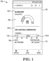
- FIG 1 is an illustration of a display provided on a user interface 100 showing an aspirating smoke detector device operational analysis 102, generated in accordance with one or more embodiments of the present disclosure.
- the aspirating smoke detector device operational analysis 102 can include real-time operational parameters 104-1, 104-2 (referred to collectively herein as real-time operational parameters 104).
- the real-time operational parameters 104 can include a blower speed 106, an air flow rate 108, and an air flow temperature 110.
- the aspirating smoke detector device operational analysis 102 can be generated by a mobile device or a tablet (e.g., mobile device 726, as described in connection with Figure 7 ) based on operational information associated with an aspirating smoke detector device. Operational information associated with the aspirating smoke detector device can be received by the mobile device from the aspirating smoke detector device located in a facility. Such operational information may be received via a network relationship between the aspirating smoke detector device and the mobile device, as is further described in connection with Figure 2 .
- the operational information associated with the aspirating smoke detector device can be data relating to operation of the aspirating smoke detector device.
- operational information can be data collected by various sensors included with the aspirating smoke detector device during operation of the aspirating smoke detector device. Such data may be utilized to illustrate various operational parameters of the aspirating smoke detector device, as is further described herein.
- the mobile device can generate, using the received operational information, the aspirating smoke detector device operational analysis 102.
- the aspirating smoke detector device operational analysis 102 ca include real-time operational parameters 104 associated with the aspirating smoke detector device, as is further described herein.
- the term "real-time operational parameter" refers to a value relating to operation of a device that is generated within a specified timeframe so as to provide feedback regarding operation of the device.
- the real-time operational parameters 104 may be values that describe operation of the aspirating smoke detector device, where such values are generated within a short timeframe so as to provide a sufficiently immediate indication of the operation of the aspirating smoke detector device.
- the aspirating smoke detector device operational analysis 102 may include display of multiple real-time operational parameters 104.
- the real-time operational parameter 104-1 can, for instance, be a blower speed 106 of a blower included in the aspirating smoke detector device.
- the aspirating smoke detector device can utilize a blower to draw gas (e.g., air) from the facility into a sensor included in the aspirating smoke detector device.
- the blower can operate to draw gas into and cause gas to flow through the aspirating smoke detector device.
- the sensor included in the aspirating smoke detector device can sample the gas to detect the presence of smoke. Such gas can be drawn through a network of pipes throughout the facility into the sensor of the aspirating smoke detector device.
- the blower of the aspirating smoke detector device can operate at various speeds as indicated by the blower speed 106. As indicated in Figure 1 , the blower of the aspirating smoke detector device may be operating at 2,800 rotations per minute (RPM).
- RPM rotations per minute
- the user interface 100 can display the real-time operational parameters 104 graphically on the user interface 100.
- the blower of the aspirating smoke detector device can be operating at 2,800 RPM and the blower speed can be indicated graphically on the user interface 100 as a half-circle bar graph.
- the lowest blower speed can be 0 RPM and the highest blower speed can be 7,000 RPM.
- the half-circle bar graph can be "filled" to around 1 ⁇ 4 of the way full to indicate that the real-time blower speed is around 1 ⁇ 4 (e.g., 2,800 RPM) of the highest blower speed (e.g., 7,000 RPM).
- the user interface 100 can display the real-time operational parameters 104 as a numerical value on the user interface 100.
- the blower of the aspirating smoke detector device can be operating at 2,800 RPM and the blower speed can be indicated as a numerical value on the user interface 100 as 2,800 RPM.
- the aspirating smoke detector device operational analysis 102 is described above as including a blower speed 106, embodiments of the present disclosure are not so limited.
- the aspirating smoke detector device operational analysis 102 can include multiple real-time operational parameters 104.
- the aspirating smoke detector device operational analysis 102 can further include an air flow rate 108 and/or an air flow temperature 110.
- the air flow rate 108 can be a real-time operational parameter 104 included in the aspirating smoke detector device operational analysis 102 on the user interface 100.
- the blower of the aspirating smoke detector device can draw gas through the aspirating smoke detector device at different speeds, which can result in different air flow rates of the gas through the aspirating smoke detector device.
- the user interface 100 can display the air flow rate graphically on the user interface 100.
- the air flow rate of the gas through the aspirating smoke detector device can be 45 liters per minute (L/min) and the air flow rate can be indicated graphically on the user interface 100 as a horizontal bar graph that can be "filled" in a direction to the left of the average flow rate to indicate the air flow rate through the aspirating smoke detector device is 45 L/min and is higher than the reference air flow rate of 40 L/min.
- the reference flow can be indicated via a vertical line on the horizontal bar graph.
- the aspirating smoke detector device can include a flow rate range, which can be variable. The flow rate range may be, in some examples, plus or minus 20%.
- the reference flow in Figure 1 is illustrated as being 40 L/min and the range can be minus 20% (e.g., 32 L/min) to plus 20% (e.g., 48 L/min).
- the flow rate range may be plus or minus 50%.
- the reference flow in Figure 1 is illustrated as being 40 L/min and the range can be minus 50% (e.g., 20 L/min) to plus 50% (e.g., 60 L/min).
- the user interface 100 can display the real-time operational parameters 104 as a numerical value on the user interface 100.
- the air flow rate of the gas through the aspirating smoke detector device can be 45 L/min and the air flow rate can be indicated as a numerical value on the user interface 100 as 45 L/min.
- the gas drawn through the aspirating smoke detector device can transit from a space in the facility to the detector and may be drawn at different air flow rates as a result of different blower speeds. Accordingly, the air flow temperature 110 of the gas can be a real-time operational parameter 104 included in the aspirating smoke detector device operational analysis 102 on the user interface 100.
- the user interface 100 can display the air flow temperature graphically on the user interface 100.
- the air flow temperature of the gas through the aspirating smoke detector device can be 24 degrees Celsius (°C) and the air flow temperature can be indicated graphically on the user interface 100 as a horizontal bar graph.
- the lowest air flow temperature can be -40 °C and the highest air flow rate can be 55 °C.
- the horizontal bar graph can be "filled" to indicate the air flow temperature through the aspirating smoke detector device is 24 °C.
- the user interface 100 can display the real-time operational parameters 104 as a numerical value on the user interface 100.
- the air flow temperature of the gas through the aspirating smoke detector device can be 24 °C and the air flow temperature can be indicated as a numerical value on the user interface 100 as 24 °C.
- the aspirating smoke detector device operational analysis 102 can include a plurality of real-time operational parameters 104 associated with the aspirating smoke detector device.
- the aspirating smoke detector device operational analysis 102 can further include, in some examples, threshold levels 116-1, 116-2 (referred to collectively herein as threshold levels 116) associated with each real-time operational parameter 104.
- the air flow rate 108 can include threshold levels 116-1, 116-2 shown on the horizontal bar graph.
- the horizontal bar graph can include a first threshold level 116-1 and a second threshold level 116-2.
- the first threshold level 116-1 can be, for instance, a lower threshold level of 20 L/min and the second threshold level 116-2 can be a higher threshold level of 60 L/min.
- the real-time air flow rate 108 of the aspirating smoke detector device exceeds the first threshold level 116-1 (e.g., the lower threshold level) or the second threshold level 116-2 (e.g., the higher threshold level), such instance would be displayed graphically on the user interface 100.
- the real-time operational parameters 104 exceeding a threshold level 116 may indicate an error or problem with the aspirating smoke detector device, the piping network of the aspirating smoke detector device, or any other event which may be useful for a user of the mobile device displaying the user interface 100 to know about. Such a scenario may be displayed on the user interface 100, as is further described in connection with Figures 3 and 4 .
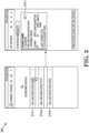
- Figure 2 is an illustration of a display provided on a user interface 200 showing a mobile device connecting with an aspirating smoke detector device 214-1, 214-2, 214-N, generated in accordance with one or more embodiments of the present disclosure.
- the user interface can display various aspirating smoke detector devices 214-1, 214-2, 214-N (referred to collectively herein as aspirating smoke detector devices 214).
- the mobile device can connect to various different aspirating smoke detector devices 214.
- the mobile device displays, on the user interface 200, aspirating smoke detector devices 214 which are within a threshold distance of the mobile device.
- a user may select aspirating smoke detector device 214-1 to connect to (e.g., as illustrated in Figure 2 as a "cursor" in the shape of a hand with an outstretched finger).
- the mobile device connects to the aspirating smoke detector devices 214 via a wireless network relationship.
- a wireless network relationship can include a local area network (LAN), wide area network (WAN), personal area network (PAN), a distributed computing environment (e.g., a cloud computing environment), storage area network (SAN), Metropolitan area network (MAN), a cellular communications network, Long Term Evolution (LTE), visible light communication (VLC), Bluetooth, Worldwide Interoperability for Microwave Access (WiMAX), Near Field Communication (NFC), infrared (IR) communication, Public Switched Telephone Network (PSTN), radio waves, and/or the Internet, among other types of network relationships.
- LAN local area network
- WAN wide area network
- PAN personal area network
- a distributed computing environment e.g., a cloud computing environment
- SAN storage area network
- MAN Metropolitan area network
- cellular communications network e.g., Long Term Evolution (LTE), visible light communication (VLC), Bluetooth, Worldwide Interoperability for Microwave Access (
- the mobile device connects to the aspirating smoke detector device via a wireless connection.
- the wireless connection can be a Bluetooth connection.
- the user interface 200 can display various attributes about the aspirating smoke detector device 214-1.
- attributes may include an identification number for the aspirating smoke detector device 214-1, its operational mode, its location, its pipe configuration, its pipe length, and/or when the mobile device was last connected with the aspirating smoke detector device 214-1.
- the mobile device may connect to the aspirating smoke detector device in response to a user selecting the "Pair Device" button via the user interface 200.
- the mobile device may automatically pair with the aspirating smoke detector device 214-1 when the mobile device is within a threshold distance of the aspirating smoke detector device 214-1.
- the mobile device can receive the operational information. For example, when the mobile device connects with the aspirating smoke detector device 214-1, the aspirating smoke detector device 214-1 can transmit the operational information to the mobile device. In response, the mobile device can generate the aspirating smoke detector device operational analysis for the aspirating smoke detector device 214-1.
- Figure 3 is an illustration of a display provided on a user interface 300 showing an air flow rate 308 and an air flow temperature 310 of an aspirating smoke detector device, generated in accordance with one or more embodiments of the present disclosure.
- the aspirating smoke detector device operational analysis 302-1 may change at a second time to be aspirating smoke detector device operational analysis 302-2.
- the mobile device can receive operational information associated with an aspirating smoke detector device in response to a wireless connection being established with the aspirating smoke detector device and generate, using the received operational information, the aspirating smoke detector device operational analysis 302.
- the aspirating smoke detector device operational analysis 302-1, 302-2 can include real-time operational parameters associated with the aspirating smoke detector device at different times, including an air flow rate 308 of gas through the aspirating smoke detector device and an air flow temperature 310 of the gas through the aspirating smoke detector device.
- the aspirating smoke detector device may include two flow channels for gas through the aspirating smoke detector device.
- the two channels can be displayed on the user interface 300 as "Channel 1" and "Channel 2".
- Channel 1 may include an associated air flow rate 308 of 45 L/min
- Channel 2 may include an associated air flow rate 308 of 25 L/min.
- the air flow rate 308 through Channel 1 of the aspirating smoke detector device can be 45 L/min, and can be displayed graphically (e.g., via the horizontal bar graph) and as a numerical value of 45 L/min.
- the air flow rate 308 through Channel 2 of the aspirating smoke detector device can be 25 L/min, and can be displayed graphically (e.g., via the horizontal bar graph) and as a numerical value of 25 L/min.
- Channel 1 may include an associated air flow temperature of 24 °C
- Channel 2 may include an air flow temperature of 24 °C.
- the air flow temperatures of Channel 1 and Channel 2 can be displayed as numerical values of 24 °C.
- the air flow rate 308 in both Channels 1 and 2 may include a first threshold level 316-1 and a second threshold level 316-2. As illustrated in Figure 3 , the air flow rates 308 through both Channel 1 and Channel 2 are within the threshold range defined by the first (e.g., lower) threshold level 316-1 and the second (e.g., upper) threshold level 316-2.
- the mobile device can color code the real-time operational parameters in the aspirating smoke detector device operational analyses 302.
- the air flow rate in Channels 1 and 2 may be color coded as green in the horizontal bar graph to indicate the air flow rates do not exceed the first threshold level 316-1 or the second threshold level 316-2 and are within a threshold range.
- Channel 1 may include an associated air flow rate 308 of 75 L/min
- Channel 2 may include an associated air flow rate 308 of 25 L/min.
- the air flow rate 308 through Channel 1 exceeds the second threshold level 316-2.
- the air flow rate 308 through Channel 1 may no longer be within the threshold range defined by the first threshold level 316-1 and the second threshold level 316-2.
- the mobile device can color code the air flow rate 308 through Channel 1 in the aspirating smoke detector device operational analyses 302-2 differently based on the air flow rate 308 exceeding the second threshold level 316-2.
- the air flow rate in Channel 1 may be color coded as red in the horizontal bar graph to indicate the air flow rate 308 through Channel 1 exceeds the second threshold level 316-2 and is outside the threshold range.
- the air flow rate in Channel 2 may still be color coded as green in the horizontal bar graph to indicate the air flow rate 308 through Channel 2 does not exceed the first threshold level 316-1 or the second threshold level 316-2.
- the mobile device can generate an alert.
- the alert may be displayed on the user interface 300.
- the alert may be an audible alert emitted by a speaker of the mobile device, the alert may be a tactile alert caused by vibration of the mobile device, etc.
- the alert may be transmitted to another computing device to alert the user and/or other users (e.g., in the form of a text message, email, etc.).
- Figure 4 is an illustration of a display provided on a user interface 400 showing a smoke level 412 of an aspirating smoke detector device, generated in accordance with one or more embodiments of the present disclosure.
- the aspirating smoke detector device operational analysis 402-1 may change at a second time to be aspirating smoke detector device operational analysis 402-2.
- the mobile device can receive operational information associated with an aspirating smoke detector device and generate the aspirating smoke detector device operational analyses 402-1, 402-2.
- the aspirating smoke detector device operational analysis 402-1, 402-2 can include real-time operational parameters associated with the aspirating smoke detector device at different times, including a smoke level 412.
- the smoke level 412 can be a real-time operational parameter included in the aspirating smoke detector device operational analysis 402-1, 402-2 on the user interface 400.
- the blower of the aspirating smoke detector device can draw gas through the aspirating smoke detector device, which can be sampled for smoke particles.
- the user interface 400 can display the smoke level 412 graphically on the user interface 400.
- the smoke level of the gas through the aspirating smoke detector device can be smoke level 1 (e.g., in Channel 1) and smoke level 3 (e.g., in Channel 2) and the smoke levels can be indicated graphically on the user interface 400 as a horizontal bar graph.
- the lowest smoke level can be 0 and the highest smoke level can be 9.
- the horizontal bar graph can be "filled" in a direction to the left of the 0 smoke level to indicate the smoke level of the gas through the aspirating smoke detector device as being smoke level 1 in Channel 1 and smoke level 3 in Channel 2.
- the user interface 400 can display the real-time operational parameters as a numerical value on the user interface 400.
- the smoke level of the gas through Channel 1 can be smoke level 1 and the smoke level can be indicated as a numerical value on the user interface 400 as Smoke Level 1.
- the smoke level of the gas through Channel 2 can be indicated as a numerical value on the user interface 400 as Smoke Level 03.
- the smoke levels 412 can include a first threshold level 418-1 for an action alert and a second threshold level 418-2 for a fire alert associated with the smoke levels 412.
- Different thresholds can be set based on an environment the aspirating smoke detector device is installed. For instance, in a dirty environment with a lot of dust, the threshold levels 418 can be set to a lower sensitivity, whereas in a cleaner environment relative to the dirty environment, the threshold levels 418 can be set to a higher sensitivity relative to the dirty environment.
- the first threshold level 418-1 can be smoke level 2 and the second threshold level 418-2 can be smoke level 4.
- the smoke level 412 in Channel 1 can be smoke level 1, which does not exceed the first threshold level 418-1.
- the mobile device can, in some examples, color code the horizontal bar graph green based on the smoke level in Channel 1 not exceeding the first threshold level 418-1. Color coding the smoke level in Channel 1 green can indicate to a user the smoke level through Channel 1 is not of concern, as there is little to no smoke present in the space in the facility.
- the smoke level in Channel 2 can be smoke level 3, which does exceed the first threshold level 418-1 but not the second threshold level 418-2.
- the mobile device can, in some examples, color code the horizontal bar graph orange based on the smoke level in Channel 2 exceeding the first threshold level 418-1 but not the second threshold level 418-2. Color coding the smoke level in Channel 2 orange can indicate to a user the smoke level through Channel 2 is more of a concern, as there may be some amount of smoke present in the space in the facility.
- the mobile device may not generate an alert in response to the smoke level exceeding the first threshold level 418-1 but not the second threshold level 418-2.
- the aspirating smoke detector device In response to the smoke level exceeding the first threshold level 418-1, the aspirating smoke detector device is to generate an action alert, and in response to the smoke level exceeding the second threshold level 418-2, the aspirating smoke detector device is to generate a fire alarm.
- the mobile device may also generate an alert in response to the smoke level exceeding the first threshold level 418-1 and/or the second threshold level 418-2.
- the smoke level 412 in Channel 1 can be smoke level 1, which does not exceed the first threshold level 418-1.
- the mobile device can, in some examples, color code the horizontal bar graph green based on the smoke level in Channel 1 not exceeding the first threshold level 418-1. Color coding the smoke level in Channel 1 green can indicate to a user the smoke level through Channel 1 is not of concern, as there is little to no smoke present in the space in the facility.
- the smoke level in Channel 2 can be smoke level 7, which exceeds both the first threshold level 418-1 and the second threshold level 418-2.
- the mobile device can, in some examples, color code the horizontal bar graph red based on the smoke level in Channel 2 exceeding the first threshold level 418-1 and the second threshold level 418-2. Color coding the smoke level in Channel 2 red can indicate to a user the smoke level through Channel 2 is of concern, as there may be a fire related event occurring that is generating smoke in the space in the facility.
- the mobile device may generate an alert in response to the smoke level exceeding the first threshold level 418-1 and the second threshold level 418-2, and the alert may be the same type of alert or a different type of alert as the alert generated in response to the smoke level exceeding the first threshold level 418-1 but not the second threshold level 418-2.
- Figure 5 is an illustration of a display provided on a user interface 500 showing modification of a real-time operational parameter of an aspirating smoke detector device, generated in accordance with one or more embodiments of the present disclosure.
- the real-time operational parameter can be a blower speed 506.
- a user may utilize the mobile device to modify a real-time operational parameter. For example, a user may wish to modify a blower speed of a blower of the aspirating smoke detector device.
- the blower speed may be speed level 6.
- a speed level of 6 may correspond to a blower speed of 2,800 RPM (e.g., as previously described in connection with Figure 1 ). Accordingly, the user may wish to increase the blower speed to 3,000 RPM. Accordingly, the user may increase the blower speed level to 8.
- the user may increase the blower speed level to 8 via the user interface 500 of the mobile device.
- the mobile device can receive an input to modify the real-time operational parameter (e.g., the blower speed).
- the mobile device may receive the input via a touch-screen display.
- the mobile device can cause the aspirating smoke detector device to modify the real-time operational parameter in response to the user interface receiving the input.
- the mobile device can receive the input at the modify parameter 520 button displayed on the user interface 500 to change the blower speed level from 6 to 8, and the mobile device can cause the aspirating smoke detector device to increase the blower speed from 2,800 RPM to 3,000 RPM.
- blower speed is described above as being modified by changing a blower speed level
- embodiments of the present disclosure are not so limited.
- the user may directly change, via a user input, the blower speed from 2,800 RPM to 3,000 RPM via a different modify parameter 520 button than is illustrated in Figure 5 .
- a different modify parameter 520 button may be a "slider", a numerical input (e.g., a user types in 3,000 via a keyboard/number pad input displayed on the user interface 500), etc.
- blower speed is described above as the real-time operational parameter being modified, embodiments of the present disclosure are not so limited.
- a user may change other real-time operational parameters (e.g., air flow rate, device sensitivity, etc.).
- Figure 6 is an illustration of a display provided on a user interface showing a log 624 of events 622, generated in accordance with one or more embodiments of the present disclosure.
- the log 624 may be generated by a mobile device.
- the mobile device can generate a log of the received operational information over time.
- the received operational information can indicate to a user operational status of the aspirating smoke detector device in the form of events 622-1, 622-2, 622-3, 622-N (referred to collectively herein as events 622).
- event 622-1 can be a low air flow alert, indicating the air flow rate of the gas through a channel of the aspirating smoke detector device may be low. A user may then investigate the cause of the low air flow rate.
- Other events 622 may include an event 622-2 indicating a battery powering the aspirating smoke detector device has been discharged, an event 622-3 indicating an air flow fault, an event 622-N indicating the voltage of the aspirating smoke detector device is low, etc. Such events 622 may be determined from the operational information by the mobile device and displayed on the user interface 600 via the log 624.
- the mobile device may generate a report associated with the log 624.
- the report may include a description of the operation of the aspirating smoke detector device over a time period, including the log 624 of the events 622, and may be exportable for printing, presentation, etc.
- the report may be displayed on the user interface 600.
- An aspirating smoke detector device operational analysis can allow a user to quickly determine a status of an aspirating smoke detector device, reducing a user's cognitive workload and increasing efficiency. Further, an aspirating smoke detector device operational analysis can allow for problems arising in the aspirating smoke detector device and/or associated network of piping to be identified and fixed, ensuring proper operation of the aspirating smoke detector device in the case of a fire event in the facility.
- Figure 7 is a mobile device 726 and an aspirating smoke detector device 714 for an aspirating smoke detector device operational analysis, in accordance with one or more embodiments of the present disclosure.
- the mobile device 726 can include a user interface 700, memory 730, and a processor 728 for an aspirating smoke detector device operational analysis in accordance with the present disclosure.
- the mobile device 726 can be, for example, a device that is (or can be) carried and/or worn by a user.
- the mobile device 726 can be a phone (e.g., a smart phone), a tablet, a personal digital assistant (PDA), smart glasses, and/or a wrist-worn device (e.g., a smart watch), among other types of mobile devices.
- a phone e.g., a smart phone
- PDA personal digital assistant
- smart glasses e.g., a smart watch
- a wrist-worn device e.g., a smart watch
- the memory 730 can be any type of storage medium that can be accessed by the processor 728 to perform various examples of the present disclosure.
- the memory 730 can be a non-transitory computer readable medium having computer readable instructions (e.g., computer program instructions) stored thereon that are executable by the processor 728 for an aspirating smoke detector device operational analysis in accordance with the present disclosure.
- the computer readable instructions can be executable by the processor 728 to redundantly generate the aspirating smoke detector device operational analysis.
- the memory 730 can be volatile or nonvolatile memory.
- the memory 730 can also be removable (e.g., portable) memory, or non-removable (e.g., internal) memory.
- the memory 730 can be random access memory (RAM) (e.g., dynamic random access memory (DRAM) and/or phase change random access memory (PCRAM)), read-only memory (ROM) (e.g., electrically erasable programmable read-only memory (EEPROM) and/or compact-disc read-only memory (CD-ROM)), flash memory, a laser disc, a digital versatile disc (DVD) or other optical storage, and/or a magnetic medium such as magnetic cassettes, tapes, or disks, among other types of memory.
- RAM random access memory
- DRAM dynamic random access memory
- PCRAM phase change random access memory
- ROM read-only memory
- EEPROM electrically erasable programmable read-only memory
- CD-ROM compact-disc read-only memory
- flash memory a laser disc
- memory 730 is illustrated as being located within mobile device 726, embodiments of the present disclosure are not so limited.
- memory 730 can also be located internal to another computing resource (e.g., enabling computer readable instructions to be downloaded over the Internet or another wired or wireless connection).
- the mobile device 726 includes a user interface 700.
- the user interface 700 can display the aspirating smoke detector device operational analysis (e.g., as previously described in connection with Figures 1-6 ) in a display.
- a user (e.g., operator) of the mobile device 726 can interact with the mobile device 726 via the user interface 700.
- the user interface 700 can provide (e.g., display and/or present) information to the user of mobile device 726, and/or receive information from (e.g., input by) the user of mobile device 726.
- GUI graphical user interface
- the display can be, for instance, a touch-screen (e.g., the GUI can include touch-screen capabilities).
- a display can include a television, computer monitor, mobile device screen, other type of display device, or any combination thereof, connected to the mobile device 726 and configured to receive a video signal output from the mobile device 726.
- the user interface 700 can be localized to any language.
- the user interface 700 can display the aspirating smoke detector device operational analysis in any language, such as English, Spanish, German, French, Mandarin, Arabic, Japanese, Hindi, etc.
Landscapes
- Engineering & Computer Science (AREA)
- Physics & Mathematics (AREA)
- General Physics & Mathematics (AREA)
- Theoretical Computer Science (AREA)
- Computer Networks & Wireless Communication (AREA)
- Signal Processing (AREA)
- General Engineering & Computer Science (AREA)
- Computer Security & Cryptography (AREA)
- Human Computer Interaction (AREA)
- Chemical & Material Sciences (AREA)
- Analytical Chemistry (AREA)
- Business, Economics & Management (AREA)
- Emergency Management (AREA)
- Fire-Detection Mechanisms (AREA)
- Fire Alarms (AREA)
Claims (13)
- Mobile Vorrichtung (726) für eine Ansaugrauchmeldervorrichtungs-Betriebsanalyse (102, 302, 402), umfassend:
einen Speicher (730); und gekennzeichnet durch ferner umfassend:eine Benutzerschnittstelle (100, 200, 300, 400, 500, 600, 700), undeinen Prozessor (728), der dazu konfiguriert ist, im Speicher (730) gespeicherte ausführbare Anweisungen auszuführen, um:
eine Vielzahl von Ansaugrauchmeldervorrichtungen innerhalb einer Schwellendistanz der mobilen Vorrichtung drahtlos zu verbinden;über die Benutzerschnittstelle (100, 200, 300, 400, 500, 600, 700) der mobilen Vorrichtung (726) eine Auswahl einer Ansaugrauchmeldervorrichtung (214, 714) aus der Vielzahl von Ansaugrauchmeldervorrichtungen (214, 714) innerhalb einer Schwellendistanz der mobilen Vorrichtung (726) zu empfangen, die auf der Benutzerschnittstelle angezeigt wird;über die drahtlose Verbindung Betriebsinformationen, die der ausgewählten Ansaugrauchmeldervorrichtung (214, 714) zugehörig sind, zu empfangen; undunter Verwendung der empfangenen Betriebsinformationen eine Ansaugrauchmeldervorrichtungs-Betriebsanalyse (102, 302, 402) zu erzeugen, die einen Echtzeitbetriebsparameter (104) beinhaltet, welcher der ausgewählten Ansaugrauchmeldervorrichtung (214, 714) zugehörig ist; undwobei die Benutzerschnittstelle (100, 200, 300, 400, 500, 600, 700) dazu konfiguriert ist, die Vielzahl von Ansaugrauchmeldervorrichtungen (214, 714) und die Ansaugrauchmeldervorrichtungs-Betriebsanalyse (102, 302, 402) anzuzeigen. - Mobile Vorrichtung (726) nach Anspruch 1, wobei die Benutzerschnittstelle (100, 200, 300, 400, 500, 600, 700) dazu konfiguriert ist, den Echtzeitbetriebsparameter (104) graphisch auf der Benutzerschnittstelle (100, 200, 300, 400, 500, 600, 700) anzuzeigen.
- Mobile Vorrichtung (726) nach Anspruch 1, wobei die Benutzerschnittstelle (100, 200, 300, 400, 500, 600, 700) dazu konfiguriert ist, den Echtzeitbetriebsparameter (104) als einen Zahlenwert auf der Benutzerschnittstelle (100, 200, 300, 400, 500, 600, 700) anzuzeigen.
- Mobile Vorrichtung nach Anspruch 1, wobei die drahtlose Verbindung eine Bluetooth-Verbindung ist.
- Mobile Vorrichtung (726) nach Anspruch 1, wobei:die Benutzerschnittstelle (100, 200, 300, 400, 500, 600, 700) dazu konfiguriert ist, eine Eingabe zu empfangen, um den Echtzeitbetriebsparameter (104) zu ändern; undder Prozessor (728) dazu konfiguriert ist, die Ansaugrauchmeldervorrichtung (214, 714) zu veranlassen, den Echtzeitbetriebsparameter (104) als Antwort darauf zu ändern, dass die Benutzerschnittstelle (100, 200, 300, 400, 500, 600, 700) die Eingabe empfängt.
- Nichtflüchtiges computerlesbares Medium, das darauf gespeicherte computerlesbare Anweisungen aufweist, die von einem Prozessor (728) dazu ausführbar sind:eine Vielzahl von Ansaugrauchmeldervorrichtungen innerhalb einer Schwellendistanz einer mobilen Vorrichtung drahtlos zu verbinden;die Vielzahl von Ansaugrauchmeldervorrichtungen über eine Benutzerschnittstelle (100, 200, 300, 400, 500, 600, 700) anzuzeigen;über die Benutzerschnittstelle (100, 200, 300, 400, 500, 600, 700) eine Auswahl einer Ansaugrauchmeldervorrichtung (214, 714) aus der Vielzahl von Ansaugrauchmeldervorrichtungen (214, 714) innerhalb einer Schwellendistanz der mobilen Vorrichtung (726) zu empfangen, die auf der Benutzerschnittstelle angezeigt wird;über die zu der Ansaugrauchmeldervorrichtung (214, 714) hergestellte drahtlose Verbindung Betriebsinformationen zu empfangen, die der ausgewählten Ansaugrauchmeldervorrichtung (214, 714) zugehörig sind;unter Verwendung der empfangenen Betriebsinformationen eine Ansaugrauchmeldervorrichtungs-Betriebsanalyse (102, 302, 402) zu erzeugen, welche Folgendes beinhaltet:einen Echtzeitbetriebsparameter (104), welcher der ausgewählten Ansaugrauchmeldervorrichtung (214, 714) zugehörig ist; undeinen Schwellenwert (116, 316, 418), welcher dem Echtzeitbetriebsparameter (104) zugehörig ist; unddie Ansaugrauchmeldervorrichtungs-Betriebsanalyse (102, 302, 402) über die Benutzerschnittstelle (100, 200, 300, 400, 500, 600, 700) anzuzeigen.
- Computerlesbares Medium nach Anspruch 6, wobei der Echtzeitbetriebsparameter (104) eine Luftströmungsgeschwindigkeit (108, 308) von Gas durch die Ansaugrauchmeldervorrichtung (214, 714) ist.
- Computerlesbares Medium nach Anspruch 6, wobei der Echtzeitbetriebsparameter (104) eine Luftströmungstemperatur (110, 310) von Gas durch die Ansaugrauchmeldervorrichtung (214, 714) ist.
- Computerlesbares Medium nach Anspruch 6, wobei der Echtzeitbetriebsparameter (104) ein Rauchwert (412) von Gas durch die Ansaugrauchmeldervorrichtung (214, 714) ist.
- Computerlesbares Medium nach Anspruch 6, wobei der Echtzeitbetriebsparameter (104) eine Gebläsedrehzahl (106, 506) eines Gebläses ist, das in der Ansaugrauchmeldervorrichtung (214, 714) beinhaltet ist.
- Computerlesbares Medium nach Anspruch 6, wobei die computerlesbaren Anweisungen von dem Prozessor (728) dazu ausführbar sind, einen Alarm als Antwort darauf zu erzeugen, dass der Echtzeitbetriebsparameter (104) den Schwellenwert (116, 316, 418) überschreitet.
- Computerlesbares Medium nach Anspruch 6, wobei die computerlesbaren Anweisungen von dem Prozessor (728) dazu ausführbar sind, den Echtzeitbetriebsparameter (104) in der Ansaugrauchmeldervorrichtungs-Betriebsanalyse (102, 302, 402) farblich zu kodieren.
- Computerlesbares Medium nach Anspruch 6, wobei die computerlesbaren Anweisungen von dem Prozessor (728) dazu ausführbar sind:ein Protokoll (624) der empfangenen Betriebsinformationen im Zeitverlauf zu erzeugen;einen Bericht, welcher dem Protokoll (624) zugehörig ist, zu erzeugen; undden Bericht auf der Benutzerschnittstelle (100, 200, 300, 400, 500, 600, 700) anzuzeigen.
Priority Applications (1)
| Application Number | Priority Date | Filing Date | Title |
|---|---|---|---|
| EP24201501.4A EP4459589A3 (de) | 2021-09-07 | 2022-08-22 | Operationsanalyse einer ansaugrauchmeldervorrichtung |
Applications Claiming Priority (1)
| Application Number | Priority Date | Filing Date | Title |
|---|---|---|---|
| US17/467,965 US11610472B1 (en) | 2021-09-07 | 2021-09-07 | Aspirating smoke detector device operational analysis |
Related Child Applications (2)
| Application Number | Title | Priority Date | Filing Date |
|---|---|---|---|
| EP24201501.4A Division-Into EP4459589A3 (de) | 2021-09-07 | 2022-08-22 | Operationsanalyse einer ansaugrauchmeldervorrichtung |
| EP24201501.4A Division EP4459589A3 (de) | 2021-09-07 | 2022-08-22 | Operationsanalyse einer ansaugrauchmeldervorrichtung |
Publications (2)
| Publication Number | Publication Date |
|---|---|
| EP4145417A1 EP4145417A1 (de) | 2023-03-08 |
| EP4145417B1 true EP4145417B1 (de) | 2024-12-11 |
Family
ID=83049684
Family Applications (2)
| Application Number | Title | Priority Date | Filing Date |
|---|---|---|---|
| EP22191553.1A Active EP4145417B1 (de) | 2021-09-07 | 2022-08-22 | Betriebsanalyse von ansaugrauchmeldern |
| EP24201501.4A Pending EP4459589A3 (de) | 2021-09-07 | 2022-08-22 | Operationsanalyse einer ansaugrauchmeldervorrichtung |
Family Applications After (1)
| Application Number | Title | Priority Date | Filing Date |
|---|---|---|---|
| EP24201501.4A Pending EP4459589A3 (de) | 2021-09-07 | 2022-08-22 | Operationsanalyse einer ansaugrauchmeldervorrichtung |
Country Status (3)
| Country | Link |
|---|---|
| US (3) | US11610472B1 (de) |
| EP (2) | EP4145417B1 (de) |
| CN (1) | CN115775444A (de) |
Families Citing this family (4)
| Publication number | Priority date | Publication date | Assignee | Title |
|---|---|---|---|---|
| EP4089657A1 (de) * | 2021-05-10 | 2022-11-16 | Carrier Fire & Security EMEA BV | Ansaugendes detektionssystem |
| US11610472B1 (en) | 2021-09-07 | 2023-03-21 | Honeywell International Inc. | Aspirating smoke detector device operational analysis |
| US12449288B2 (en) * | 2022-02-09 | 2025-10-21 | Honeywell International Inc. | Flow condition testing procedure of an aspirating smoke detector device |
| WO2024170311A1 (de) * | 2023-02-17 | 2024-08-22 | Siemens Schweiz Ag | Überprüfung der transportzeit eines ansaugrauchmelders mit hilfe eines benutzers mittels eines mobilen endgeräts |
Family Cites Families (43)
| Publication number | Priority date | Publication date | Assignee | Title |
|---|---|---|---|---|
| US4173886A (en) * | 1978-06-27 | 1979-11-13 | British Gas Corporation | Gas detectors |
| US7564365B2 (en) * | 2002-08-23 | 2009-07-21 | Ge Security, Inc. | Smoke detector and method of detecting smoke |
| US20060220886A1 (en) * | 2004-09-02 | 2006-10-05 | Robertson Ronald E | Pro Locator Fire Sniffer |
| US7782197B2 (en) * | 2007-11-15 | 2010-08-24 | Honeywell International Inc. | Systems and methods of detection using fire modeling |
| JP5026320B2 (ja) * | 2008-03-28 | 2012-09-12 | 能美防災株式会社 | 煙感知器 |
| US8186201B2 (en) * | 2008-08-26 | 2012-05-29 | Honeywell International Inc. | Multi-sensor gas detectors |
| DE102009031099A1 (de) * | 2009-06-29 | 2010-12-30 | Ista International Gmbh | Rauchwarnmelder und Verfahren zur Überprüfung der Verschmutzung der Rauchdurchtrittsöffnungen |
| US20110074590A1 (en) * | 2009-09-28 | 2011-03-31 | Eric Sacknoff | Smoke detector with wireless muting system |
| US9978251B2 (en) * | 2009-12-28 | 2018-05-22 | Honeywell International Inc. | Wireless location-based system and method for detecting hazardous and non-hazardous conditions |
| CN102314745B (zh) | 2010-07-06 | 2013-07-10 | 鼎盛特安全预警技术(北京)有限公司 | 感烟火灾探测报警器 |
| CN201796460U (zh) | 2010-08-28 | 2011-04-13 | 东北电网有限公司大连培训中心 | 极早期空气采样烟雾探测系统 |
| DE102010048982B4 (de) * | 2010-09-03 | 2022-06-09 | Inficon Gmbh | Lecksuchgerät |
| US9396637B2 (en) * | 2012-07-13 | 2016-07-19 | Walter Kidde Portable Equipment, Inc | Photoelectric smoke detector with drift compensation |
| FR3000271B1 (fr) * | 2012-12-21 | 2016-03-11 | Finsecur | Dispositif de detection d'incendie |
| US9459243B2 (en) | 2013-04-30 | 2016-10-04 | Life Safety Distribution Ag | Ultrasonic transducers in aspirating smoke detectors for transport time measurement |
| US9520054B2 (en) | 2013-10-07 | 2016-12-13 | Google Inc. | Mobile user interface for smart-home hazard detector configuration |
| WO2015156867A1 (en) * | 2014-04-09 | 2015-10-15 | Wilging Philip J | Wireless audio system using smoke detectors with integrated audio systems paired for mobile device output |
| US9410712B2 (en) | 2014-10-08 | 2016-08-09 | Google Inc. | Data management profile for a fabric network |
| CN204511522U (zh) | 2015-03-25 | 2015-07-29 | 河南理工大学 | 煤矿通风与瓦斯含量实时监测系统 |
| KR20180109847A (ko) * | 2015-10-26 | 2018-10-08 | 상하이 이글 세이프티 이큅먼트 리미티드 | 모니터링 시스템 및 방법 |
| CN205091871U (zh) * | 2015-11-10 | 2016-03-16 | 遵义晨曦科贸有限公司 | 一种智能安防信息采集系统 |
| CN106815987B (zh) * | 2015-11-30 | 2021-01-26 | 弗兰克公司 | 检测器到检测器的警报 |
| JP2019512825A (ja) * | 2016-02-12 | 2019-05-16 | デトコン, インコーポレイテッドDetcon, Inc. | ワイヤレスガス検出センサ |
| KR102442058B1 (ko) * | 2016-12-09 | 2022-09-13 | 삼성전자주식회사 | 전자 장치 및 그의 제어방법 |
| US11231402B2 (en) * | 2017-06-27 | 2022-01-25 | Integrated Device Technology, Inc. | Calibrated mobile gas sensor |
| CN111033252A (zh) * | 2017-08-25 | 2020-04-17 | 周锦富 | 用于校准气体检测装置的系统和方法 |
| US20190124194A1 (en) * | 2017-10-23 | 2019-04-25 | Honeywell International Inc. | Near-field communication initiated bluetooth pairing between mobile device and gas detector |
| ES2866400T3 (es) * | 2018-01-16 | 2021-10-19 | Carrier Corp | Sistema de detección y advertencia de monóxido de carbono para un dispositivo de teléfono portátil |
| US10969373B2 (en) * | 2018-01-29 | 2021-04-06 | Honeywell International Inc. | System and method for wireless portable gas detecting and communication |
| EP3581035A1 (de) * | 2018-06-13 | 2019-12-18 | Linde Aktiengesellschaft | Integriertes gaszufuhr- und -entfernungssystem |
| CN109030374A (zh) * | 2018-08-16 | 2018-12-18 | 上海禾赛光电科技有限公司 | 用于激光气体检测仪的数据管理方法及数据管理终端 |
| CN208722373U (zh) * | 2018-09-14 | 2019-04-09 | 安徽磐众信息科技有限公司 | 一种智能烟雾报警器 |
| SG10201900219RA (en) | 2019-01-10 | 2020-08-28 | Lingjack Eng Works Pte Ltd | Fire safety system using internet of things technology |
| US20200320857A1 (en) | 2019-04-05 | 2020-10-08 | Honeywell International Inc. | Unmanned system (us) for safety device testing |
| US10977920B2 (en) * | 2019-06-21 | 2021-04-13 | Johnson Controls Technology Company | Fire safety system with integrated lighting devices |
| DE102019122514A1 (de) * | 2019-08-21 | 2021-02-25 | LUPUS-ELECTRONICS GmbH | Verfahren zur Zuordnung eines zu registrierenden Rauchmelders und ein entsprechendes Rauchmelderverwaltungssystem |
| US11288951B2 (en) * | 2019-11-13 | 2022-03-29 | Carrier Corporation | Identification of anomaly on a detector |
| ES2932701T3 (es) * | 2019-12-23 | 2023-01-24 | Carrier Corp | Detector de puntos para sistema de alarma contra incendios |
| US10929735B1 (en) * | 2020-02-03 | 2021-02-23 | Capital One Services, Llc | Smart card with sensors for detecting environmental conditions |
| US11268730B2 (en) * | 2020-04-08 | 2022-03-08 | Edward Helbling | Energy management system controller and method |
| US11143641B1 (en) * | 2021-04-05 | 2021-10-12 | Vivante Health, Inc. | Gas sensor calibration method |
| US11761875B2 (en) * | 2021-06-01 | 2023-09-19 | Honeywell International Inc. | Adjusting for air flow temperature changes in an aspirating smoke detector |
| US11610472B1 (en) * | 2021-09-07 | 2023-03-21 | Honeywell International Inc. | Aspirating smoke detector device operational analysis |
-
2021
- 2021-09-07 US US17/467,965 patent/US11610472B1/en active Active
-
2022
- 2022-03-23 US US17/701,925 patent/US11837074B2/en active Active
- 2022-08-15 CN CN202210972730.2A patent/CN115775444A/zh active Pending
- 2022-08-22 EP EP22191553.1A patent/EP4145417B1/de active Active
- 2022-08-22 EP EP24201501.4A patent/EP4459589A3/de active Pending
-
2023
- 2023-12-04 US US18/527,518 patent/US12400539B2/en active Active
Non-Patent Citations (4)
| Title |
|---|
| WAGNER BRANDSCHUTZLÖSUNGEN: "DIAGNOSTIC TOOL DIAG3", 1 November 2014 (2014-11-01), pages 1 - 15, XP093102738, Retrieved from the Internet <URL:http> [retrieved on 20231117] * |
| WAGNER BRANDSCHUTZLÖSUNGEN: "Installation Instructions Diagnostic Device for AD2-C11 Rev.d, TITANUS 3000 and SuperSens", 28 February 1999 (1999-02-28), pages 1 - 4, XP093102820, Retrieved from the Internet <URL:https:----> * |
| WAGNER BRANDSCHUTZLÖSUNGEN: "Wagner diagnostic tool DIAG3", 1 November 2014 (2014-11-01), pages 1 - 15, XP093102743, Retrieved from the Internet <URL:http> * |
| WAGNER BRANDSCHUTZLÖSUNGEN: "Wagner diagnostic tool DIAG3", 1 November 2014 (2014-11-01), Wagner Brandschutzlösungen, pages 1 - 15, XP093102810, Retrieved from the Internet <URL:---> * |
Also Published As
| Publication number | Publication date |
|---|---|
| US12400539B2 (en) | 2025-08-26 |
| US20230076348A1 (en) | 2023-03-09 |
| EP4145417A1 (de) | 2023-03-08 |
| US11837074B2 (en) | 2023-12-05 |
| US20230072959A1 (en) | 2023-03-09 |
| US20240194052A1 (en) | 2024-06-13 |
| CN115775444A (zh) | 2023-03-10 |
| EP4459589A2 (de) | 2024-11-06 |
| EP4459589A3 (de) | 2025-04-16 |
| US11610472B1 (en) | 2023-03-21 |
Similar Documents
| Publication | Publication Date | Title |
|---|---|---|
| EP4145417B1 (de) | Betriebsanalyse von ansaugrauchmeldern | |
| US11495098B2 (en) | Aggregate monitor data in real-time by worker | |
| US8400317B2 (en) | System for providing real time locating and gas exposure monitoring | |
| EP4075401B1 (de) | Bestimmung und benachrichtigung eines ortes eines gebäudesicherheitssystems | |
| US10365260B2 (en) | Image based surveillance system | |
| US9188574B2 (en) | Mobile gas detection cart with wireless transceiver | |
| KR102158840B1 (ko) | 실시간 화재 감지 시스템 및 그 감지 방법 | |
| KR102245887B1 (ko) | 실내 화재예방 알림 시스템 및 그 방법 | |
| AU2018278971B2 (en) | Gas-measuring device | |
| EP4557253A1 (de) | Tragbare vorrichtung zur notfallevakuierung und -rettung | |
| JP2009277125A (ja) | 防災向け警報システム | |
| JP6495761B2 (ja) | 核燃料再処理施設の事故災害時支援システム、方法及びプログラム | |
| JP2016062601A (ja) | センサ関連データの処理のカスタマイズ |
Legal Events
| Date | Code | Title | Description |
|---|---|---|---|
| PUAI | Public reference made under article 153(3) epc to a published international application that has entered the european phase |
Free format text: ORIGINAL CODE: 0009012 |
|
| STAA | Information on the status of an ep patent application or granted ep patent |
Free format text: STATUS: REQUEST FOR EXAMINATION WAS MADE |
|
| 17P | Request for examination filed |
Effective date: 20220822 |
|
| AK | Designated contracting states |
Kind code of ref document: A1 Designated state(s): AL AT BE BG CH CY CZ DE DK EE ES FI FR GB GR HR HU IE IS IT LI LT LU LV MC MK MT NL NO PL PT RO RS SE SI SK SM TR |
|
| P01 | Opt-out of the competence of the unified patent court (upc) registered |
Effective date: 20230523 |
|
| STAA | Information on the status of an ep patent application or granted ep patent |
Free format text: STATUS: EXAMINATION IS IN PROGRESS |
|
| 17Q | First examination report despatched |
Effective date: 20231123 |
|
| GRAP | Despatch of communication of intention to grant a patent |
Free format text: ORIGINAL CODE: EPIDOSNIGR1 |
|
| STAA | Information on the status of an ep patent application or granted ep patent |
Free format text: STATUS: GRANT OF PATENT IS INTENDED |
|
| INTG | Intention to grant announced |
Effective date: 20240709 |
|
| GRAS | Grant fee paid |
Free format text: ORIGINAL CODE: EPIDOSNIGR3 |
|
| GRAA | (expected) grant |
Free format text: ORIGINAL CODE: 0009210 |
|
| STAA | Information on the status of an ep patent application or granted ep patent |
Free format text: STATUS: THE PATENT HAS BEEN GRANTED |
|
| AK | Designated contracting states |
Kind code of ref document: B1 Designated state(s): AL AT BE BG CH CY CZ DE DK EE ES FI FR GB GR HR HU IE IS IT LI LT LU LV MC MK MT NL NO PL PT RO RS SE SI SK SM TR |
|
| REG | Reference to a national code |
Ref country code: GB Ref legal event code: FG4D |
|
| REG | Reference to a national code |
Ref country code: CH Ref legal event code: EP |
|
| REG | Reference to a national code |
Ref country code: IE Ref legal event code: FG4D |
|
| REG | Reference to a national code |
Ref country code: DE Ref legal event code: R096 Ref document number: 602022008564 Country of ref document: DE |
|
| REG | Reference to a national code |
Ref country code: LT Ref legal event code: MG9D |
|
| PG25 | Lapsed in a contracting state [announced via postgrant information from national office to epo] |
Ref country code: HR Free format text: LAPSE BECAUSE OF FAILURE TO SUBMIT A TRANSLATION OF THE DESCRIPTION OR TO PAY THE FEE WITHIN THE PRESCRIBED TIME-LIMIT Effective date: 20241211 |
|
| PG25 | Lapsed in a contracting state [announced via postgrant information from national office to epo] |
Ref country code: FI Free format text: LAPSE BECAUSE OF FAILURE TO SUBMIT A TRANSLATION OF THE DESCRIPTION OR TO PAY THE FEE WITHIN THE PRESCRIBED TIME-LIMIT Effective date: 20241211 |
|
| PG25 | Lapsed in a contracting state [announced via postgrant information from national office to epo] |
Ref country code: BG Free format text: LAPSE BECAUSE OF FAILURE TO SUBMIT A TRANSLATION OF THE DESCRIPTION OR TO PAY THE FEE WITHIN THE PRESCRIBED TIME-LIMIT Effective date: 20241211 |
|
| REG | Reference to a national code |
Ref country code: NL Ref legal event code: MP Effective date: 20241211 |
|
| PG25 | Lapsed in a contracting state [announced via postgrant information from national office to epo] |
Ref country code: ES Free format text: LAPSE BECAUSE OF FAILURE TO SUBMIT A TRANSLATION OF THE DESCRIPTION OR TO PAY THE FEE WITHIN THE PRESCRIBED TIME-LIMIT Effective date: 20241211 |
|
| PG25 | Lapsed in a contracting state [announced via postgrant information from national office to epo] |
Ref country code: NO Free format text: LAPSE BECAUSE OF FAILURE TO SUBMIT A TRANSLATION OF THE DESCRIPTION OR TO PAY THE FEE WITHIN THE PRESCRIBED TIME-LIMIT Effective date: 20250311 |
|
| PG25 | Lapsed in a contracting state [announced via postgrant information from national office to epo] |
Ref country code: GR Free format text: LAPSE BECAUSE OF FAILURE TO SUBMIT A TRANSLATION OF THE DESCRIPTION OR TO PAY THE FEE WITHIN THE PRESCRIBED TIME-LIMIT Effective date: 20250312 Ref country code: LV Free format text: LAPSE BECAUSE OF FAILURE TO SUBMIT A TRANSLATION OF THE DESCRIPTION OR TO PAY THE FEE WITHIN THE PRESCRIBED TIME-LIMIT Effective date: 20241211 |
|
| PG25 | Lapsed in a contracting state [announced via postgrant information from national office to epo] |
Ref country code: RS Free format text: LAPSE BECAUSE OF FAILURE TO SUBMIT A TRANSLATION OF THE DESCRIPTION OR TO PAY THE FEE WITHIN THE PRESCRIBED TIME-LIMIT Effective date: 20250311 |
|
| PG25 | Lapsed in a contracting state [announced via postgrant information from national office to epo] |
Ref country code: NL Free format text: LAPSE BECAUSE OF FAILURE TO SUBMIT A TRANSLATION OF THE DESCRIPTION OR TO PAY THE FEE WITHIN THE PRESCRIBED TIME-LIMIT Effective date: 20241211 |
|
| REG | Reference to a national code |
Ref country code: AT Ref legal event code: MK05 Ref document number: 1751017 Country of ref document: AT Kind code of ref document: T Effective date: 20241211 |
|
| PG25 | Lapsed in a contracting state [announced via postgrant information from national office to epo] |
Ref country code: SM Free format text: LAPSE BECAUSE OF FAILURE TO SUBMIT A TRANSLATION OF THE DESCRIPTION OR TO PAY THE FEE WITHIN THE PRESCRIBED TIME-LIMIT Effective date: 20241211 |
|
| PG25 | Lapsed in a contracting state [announced via postgrant information from national office to epo] |
Ref country code: PL Free format text: LAPSE BECAUSE OF FAILURE TO SUBMIT A TRANSLATION OF THE DESCRIPTION OR TO PAY THE FEE WITHIN THE PRESCRIBED TIME-LIMIT Effective date: 20241211 |
|
| PG25 | Lapsed in a contracting state [announced via postgrant information from national office to epo] |
Ref country code: IS Free format text: LAPSE BECAUSE OF FAILURE TO SUBMIT A TRANSLATION OF THE DESCRIPTION OR TO PAY THE FEE WITHIN THE PRESCRIBED TIME-LIMIT Effective date: 20250411 |
|
| PG25 | Lapsed in a contracting state [announced via postgrant information from national office to epo] |
Ref country code: PT Free format text: LAPSE BECAUSE OF FAILURE TO SUBMIT A TRANSLATION OF THE DESCRIPTION OR TO PAY THE FEE WITHIN THE PRESCRIBED TIME-LIMIT Effective date: 20250411 |
|
| PG25 | Lapsed in a contracting state [announced via postgrant information from national office to epo] |
Ref country code: EE Free format text: LAPSE BECAUSE OF FAILURE TO SUBMIT A TRANSLATION OF THE DESCRIPTION OR TO PAY THE FEE WITHIN THE PRESCRIBED TIME-LIMIT Effective date: 20241211 |
|
| PG25 | Lapsed in a contracting state [announced via postgrant information from national office to epo] |
Ref country code: AT Free format text: LAPSE BECAUSE OF FAILURE TO SUBMIT A TRANSLATION OF THE DESCRIPTION OR TO PAY THE FEE WITHIN THE PRESCRIBED TIME-LIMIT Effective date: 20241211 Ref country code: RO Free format text: LAPSE BECAUSE OF FAILURE TO SUBMIT A TRANSLATION OF THE DESCRIPTION OR TO PAY THE FEE WITHIN THE PRESCRIBED TIME-LIMIT Effective date: 20241211 |
|
| PG25 | Lapsed in a contracting state [announced via postgrant information from national office to epo] |
Ref country code: SK Free format text: LAPSE BECAUSE OF FAILURE TO SUBMIT A TRANSLATION OF THE DESCRIPTION OR TO PAY THE FEE WITHIN THE PRESCRIBED TIME-LIMIT Effective date: 20241211 |
|
| PG25 | Lapsed in a contracting state [announced via postgrant information from national office to epo] |
Ref country code: CZ Free format text: LAPSE BECAUSE OF FAILURE TO SUBMIT A TRANSLATION OF THE DESCRIPTION OR TO PAY THE FEE WITHIN THE PRESCRIBED TIME-LIMIT Effective date: 20241211 |
|
| PG25 | Lapsed in a contracting state [announced via postgrant information from national office to epo] |
Ref country code: IT Free format text: LAPSE BECAUSE OF FAILURE TO SUBMIT A TRANSLATION OF THE DESCRIPTION OR TO PAY THE FEE WITHIN THE PRESCRIBED TIME-LIMIT Effective date: 20241211 |
|
| PG25 | Lapsed in a contracting state [announced via postgrant information from national office to epo] |
Ref country code: SE Free format text: LAPSE BECAUSE OF FAILURE TO SUBMIT A TRANSLATION OF THE DESCRIPTION OR TO PAY THE FEE WITHIN THE PRESCRIBED TIME-LIMIT Effective date: 20241211 |
|
| REG | Reference to a national code |
Ref country code: DE Ref legal event code: R097 Ref document number: 602022008564 Country of ref document: DE |
|
| PG25 | Lapsed in a contracting state [announced via postgrant information from national office to epo] |
Ref country code: DK Free format text: LAPSE BECAUSE OF FAILURE TO SUBMIT A TRANSLATION OF THE DESCRIPTION OR TO PAY THE FEE WITHIN THE PRESCRIBED TIME-LIMIT Effective date: 20241211 |
|
| PGFP | Annual fee paid to national office [announced via postgrant information from national office to epo] |
Ref country code: DE Payment date: 20250827 Year of fee payment: 4 |
|
| PLBE | No opposition filed within time limit |
Free format text: ORIGINAL CODE: 0009261 |
|
| STAA | Information on the status of an ep patent application or granted ep patent |
Free format text: STATUS: NO OPPOSITION FILED WITHIN TIME LIMIT |
|
| PGFP | Annual fee paid to national office [announced via postgrant information from national office to epo] |
Ref country code: FR Payment date: 20250825 Year of fee payment: 4 |
|
| REG | Reference to a national code |
Ref country code: CH Ref legal event code: L10 Free format text: ST27 STATUS EVENT CODE: U-0-0-L10-L00 (AS PROVIDED BY THE NATIONAL OFFICE) Effective date: 20251022 |
|
| 26N | No opposition filed |
Effective date: 20250912 |
|
| REG | Reference to a national code |
Ref country code: CH Ref legal event code: H13 Free format text: ST27 STATUS EVENT CODE: U-0-0-H10-H13 (AS PROVIDED BY THE NATIONAL OFFICE) Effective date: 20260324 |
|
| PG25 | Lapsed in a contracting state [announced via postgrant information from national office to epo] |
Ref country code: MC Free format text: LAPSE BECAUSE OF FAILURE TO SUBMIT A TRANSLATION OF THE DESCRIPTION OR TO PAY THE FEE WITHIN THE PRESCRIBED TIME-LIMIT Effective date: 20241211 |
|
| PG25 | Lapsed in a contracting state [announced via postgrant information from national office to epo] |
Ref country code: LU Free format text: LAPSE BECAUSE OF NON-PAYMENT OF DUE FEES Effective date: 20250822 |
|
| PG25 | Lapsed in a contracting state [announced via postgrant information from national office to epo] |
Ref country code: CH Free format text: LAPSE BECAUSE OF NON-PAYMENT OF DUE FEES Effective date: 20250831 |