EP4145207B1 - Optische filtervorrichtung zur beleuchtung einer probe - Google Patents
Optische filtervorrichtung zur beleuchtung einer probe Download PDFInfo
- Publication number
- EP4145207B1 EP4145207B1 EP21194934.2A EP21194934A EP4145207B1 EP 4145207 B1 EP4145207 B1 EP 4145207B1 EP 21194934 A EP21194934 A EP 21194934A EP 4145207 B1 EP4145207 B1 EP 4145207B1
- Authority
- EP
- European Patent Office
- Prior art keywords
- light
- angular
- wavelengths
- acousto
- sample
- Prior art date
- Legal status (The legal status is an assumption and is not a legal conclusion. Google has not performed a legal analysis and makes no representation as to the accuracy of the status listed.)
- Active
Links
Images


Classifications
-
- G—PHYSICS
- G02—OPTICS
- G02B—OPTICAL ELEMENTS, SYSTEMS OR APPARATUS
- G02B21/00—Microscopes
- G02B21/0004—Microscopes specially adapted for specific applications
- G02B21/002—Scanning microscopes
- G02B21/0024—Confocal scanning microscopes (CSOMs) or confocal "macroscopes"; Accessories which are not restricted to use with CSOMs, e.g. sample holders
- G02B21/0032—Optical details of illumination, e.g. light-sources, pinholes, beam splitters, slits, fibers
-
- G—PHYSICS
- G02—OPTICS
- G02B—OPTICAL ELEMENTS, SYSTEMS OR APPARATUS
- G02B21/00—Microscopes
- G02B21/0004—Microscopes specially adapted for specific applications
- G02B21/002—Scanning microscopes
- G02B21/0024—Confocal scanning microscopes (CSOMs) or confocal "macroscopes"; Accessories which are not restricted to use with CSOMs, e.g. sample holders
- G02B21/0052—Optical details of the image generation
- G02B21/0064—Optical details of the image generation multi-spectral or wavelength-selective arrangements, e.g. wavelength fan-out, chromatic profiling
-
- G—PHYSICS
- G02—OPTICS
- G02B—OPTICAL ELEMENTS, SYSTEMS OR APPARATUS
- G02B21/00—Microscopes
- G02B21/0004—Microscopes specially adapted for specific applications
- G02B21/002—Scanning microscopes
- G02B21/0024—Confocal scanning microscopes (CSOMs) or confocal "macroscopes"; Accessories which are not restricted to use with CSOMs, e.g. sample holders
- G02B21/008—Details of detection or image processing, including general computer control
-
- G—PHYSICS
- G02—OPTICS
- G02B—OPTICAL ELEMENTS, SYSTEMS OR APPARATUS
- G02B21/00—Microscopes
- G02B21/06—Means for illuminating specimens
-
- G—PHYSICS
- G02—OPTICS
- G02F—OPTICAL DEVICES OR ARRANGEMENTS FOR THE CONTROL OF LIGHT BY MODIFICATION OF THE OPTICAL PROPERTIES OF THE MEDIA OF THE ELEMENTS INVOLVED THEREIN; NON-LINEAR OPTICS; FREQUENCY-CHANGING OF LIGHT; OPTICAL LOGIC ELEMENTS; OPTICAL ANALOGUE/DIGITAL CONVERTERS
- G02F1/00—Devices or arrangements for the control of the intensity, colour, phase, polarisation or direction of light arriving from an independent light source, e.g. switching, gating or modulating; Non-linear optics
- G02F1/01—Devices or arrangements for the control of the intensity, colour, phase, polarisation or direction of light arriving from an independent light source, e.g. switching, gating or modulating; Non-linear optics for the control of the intensity, phase, polarisation or colour
- G02F1/11—Devices or arrangements for the control of the intensity, colour, phase, polarisation or direction of light arriving from an independent light source, e.g. switching, gating or modulating; Non-linear optics for the control of the intensity, phase, polarisation or colour based on acousto-optical elements, e.g. using variable diffraction by sound or like mechanical waves
-
- G—PHYSICS
- G02—OPTICS
- G02B—OPTICAL ELEMENTS, SYSTEMS OR APPARATUS
- G02B26/00—Optical devices or arrangements for the control of light using movable or deformable optical elements
- G02B26/08—Optical devices or arrangements for the control of light using movable or deformable optical elements for controlling the direction of light
- G02B26/10—Scanning systems
- G02B26/105—Scanning systems with one or more pivoting mirrors or galvano-mirrors
Definitions
- Document WO 2019/138119 A1 discloses an optical filter device according to the preamble of claim 1.
- the device includes an acousto-optical element 1 which is arranged in a beam path of an incident light beam.
- the device is configured to reduce the chromatic spread angle of the light diffracted by the acousto-optical element.
- the device includes two focusing optical systems which are arranged upstream and downstream of the acousto-optical element, respectively.
- the upstream focusing optical system is arranged such that the light rays of the incident light beam are bundled into a focus within the acousto-optical element.
- Document WO 2019/206646 A1 discloses an arrangement for multi-color illumination comprising an acousto-optical tunable filter that is configured to diffract two light components of incident illumination light into different diffraction order directions.
- An optical filter device for illuminating a sample comprises a light supply unit configured to generate input light of a predetermined spectral bandwidth in a collinear manner.
- the optical filter device further comprises an acousto-optic tunable filter configured to receive the input light and to emit diffracted output light including multiple wavelengths from the spectral bandwidth at exit angles towards the sample, said exit angles defining an angular spread among the multiple wavelengths of the output light.
- the angular spread among the multiple wavelengths of the output light is determined by an angular characteristic varying from a minimum wavelength to a maximum wavelength.
- the angular characteristic has an extremum at an intermediate wavelength between the minimum wavelength and the maximum wavelength to provide at least one group of different wavelengths having the same exit angles.
- the new filter design proposes an angular characteristic having an extremum between the minimum wavelength and the maximum wavelength which enables different wavelengths to have the same exit angle when being emitted from the acousto-optic tunable filter.
- the acousto-optic tunable filter is enabled to simultaneously illuminate a specific target region of a sample with multiple wavelengths.
- the optical filter device can be used advantageously in microscopic applications where it is important to illuminate a specific point in the sample with different wavelengths at the same time.
- an acousto-optic tunable filter can be designed such that, on the one hand, the exit angle is the same with respect to at least two wavelength and, on the other hand, any limitations that may result from the new filter design compared to conventional designs are not detrimental in the specific applications.
- the inventor recognized that it is possible to achieve the intended angular filter characteristic while limiting the light entry into the acousto-optic tunable filter to a collinear entry, and a collinear light entry over a certain spectral bandwidth is provided anyway in the applications under consideration.
- an improved optical filter device is provided for applications with collinear light entry without having to accept any limitations which would be relevant for these applications.
- the acousto-optic tunable filter is formed in accordance with a filter design determining the angular acceptance range with respect to the input light and the angular spread among the multiple wavelengths of the output light.
- the filter design may deviate from a parallel-tangent condition to reduce the angular spread among the multiple wavelengths of the output light while limiting the angular acceptance range with respect to the input light over the spectral bandwidth thereof to collinear light incidence.
- an acousto-optic tunable filter is designed to operate in the so-called parallel-tangent condition.
- a filter design which is based on the parallel-tangent condition yields an acousto-optic tunable filter with a wide angular acceptance range which corresponds to the field of view (FOV) of the filter.
- the parallel-tangent condition means that the tangents to the index surfaces on the wave-vector surfaces of the incident and the diffracted polarizations at the points of intersection of the corresponding waves are parallel to each other.
- the inventor realized that this advantage comes at the expense of a relatively large angular spread of the output light over the spectral bandwidth given by the input light, and the inventor further realized that the angular spread may be detrimental in specific applications as for example in confocal microscopy.
- the inventor found out that a new filter design deviating from the ubiquitous parallel-tangent condition enables the wavelength-dependent angular spread of the output light to be significantly reduced compared to conventional filter designs that satisfy the parallel-tangent condition.
- it When deviating from the parallel-tangent condition, it must be accepted that the angular acceptance range of the acousto-optic tunable filter with respect to the input light is reduced compared to the conventional filter design.
- the filter design is determined in relation to a reference filter design satisfying the parallel-tangent condition to reduce both the angular acceptance range with respect to the input light and the angular spread among the multiple wavelengths in comparison with the reference filter design.
- a reference filter design satisfying the parallel-tangent condition to reduce both the angular acceptance range with respect to the input light and the angular spread among the multiple wavelengths in comparison with the reference filter design.
- the filter design comprises at least one filter parameter selected from a group including an orientation of the light entrance surface, an orientation of the light emission surface, an orientation of the transducer surface, and a dimension of the transducer.
- achromatic and apochromatic designs are known in the field of optical lenses.
- optical lenses due to the dependence of the refractive index of the glass medium on the incident wavelength, the effective focal length is not the same for all wavelengths.
- chromatic aberration occurs.
- achromatic and apochromatic lens configurations use two and three types of glass materials with different refractive indices, respectively.
- the new filter design also achieves such an achromatic or apochromatic effect, it is not necessary to combine multiple filter materials to achieve this effect. Rather, the effect is achieved in the new filter design due to the wavelength-dependent refractive index and the wavelength-dependent birefringence of the filter crystal material which may be tellurium dioxide.
- the optical filter device comprises a control unit which is configured to tune the acousto-optic tunable filter for illuminating the sample with at least one group of different wavelengths at the same exit angle.
- control unit is configured to select the at least one group of different wavelengths based on the angular characteristic in response to a user input.
- a user is enabled to freely select suitable wavelengths which are collinearly emitted from the acousto-optic tunable filter.
- the control unit may further be configured to tune the acousto-optic tunable filter simultaneously to the different wavelengths of the at least one group. Thus, it is ensured that the different wavelengths of the output light are irradiated at the same time onto the sample.
- the optical filter device comprises a first light reflecting element which is configured to deflect the at least one group of different wavelengths output by the acousto-optic tunable filter into a predetermined target direction.
- a first light reflecting element which is configured to deflect the at least one group of different wavelengths output by the acousto-optic tunable filter into a predetermined target direction.
- a memory may be provided to store calibration data which represent an amount for actuating the first light reflecting elements depending on the exit angle assigned to the at least one group of different wavelengths for deflecting said group into the predetermined target direction, wherein the control unit is configured to control the first light deflecting element based on the calibration data.
- the first light deflecting element may be formed from a galvanometer mirror.
- a second light deflecting element may be provided which deflects the at least one group of different wavelengths output by the acousto-optic tunable filter onto a predetermined target position on the sample.
- the second light deflecting element may be used to scan the sample with the multiple wavelengths of the output light which are emitted from the acousto-optic tunable filter at the same exit angle.
- the optical device comprises an illumination objective configured to illuminate the sample with the output light emitted by the acousto-optic tunable filter.
- an illumination objective configured to illuminate the sample with the output light emitted by the acousto-optic tunable filter.
- the light supply unit may comprise one or more supercontinuum laser sources, for example white light lasers, without being limited thereto.
- a method for illuminating a sample comprising the steps of generating input light of a predetermined spectral bandwidth in a collinear manner, and using an acousto-optic tunable filter for receiving the input light and emitting diffracted output light including multiple wavelengths from the spectral bandwidth at exit angles towards the sample, said exit angles defining an angular spread among the multiple wavelengths of the output light.
- the angular spread among the multiple wavelengths of the output light is determined by an angular characteristic varying from a minimum wavelength to a maximum wavelength.
- the angular characteristic has an extremum at an intermediate wavelength between the minimum wavelength and the maximum wavelength to provide at least one group of different wavelengths having the same exit angle.
- the sample may be illuminated with the output light emitted from the acousto-optic tunable filter in order to perform confocal microscopy, multiphoton microscopy, Coherent Anti-Stokes Raman (CARS) microscopy, Stimulated Raman Scattering (SRS) microscopy, Sum-Frequency Generation (SFG) microscopy, Difference-Frequency Generation (DFG) microscopy, and/or Frequency-Modulated Stimulated Raman Scattering (FM-SRS) microscopy without being limited thereto.
- CARS Coherent Anti-Stokes Raman
- SRS Stimulated Raman Scattering
- SSG Sum-Frequency Generation
- DFG Difference-Frequency Generation
- FM-SRS Frequency-Modulated Stimulated Raman Scattering
- the optical filter device can be used advantageously in these applications to provide the required sample illumination
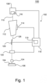
- Figure 1 shows a microscope 100 which includes an optical filter device 102 according to an embodiment.
- the microscope 100 may be configured as a confocal microscope which is used to acquire an image of a sample 104 which is arranged on a microscope stage 106.
- Figur 1 shows only those components which may help to understand the technical teaching disclosed herein.
- Figure 1 focuses on those components which are used to illuminate the sample 104.
- the microscope 100 may comprise additional components, in particular those components which are required for image acquisition as for example one or more image sensors / light sensors which are not shown in Figure 1 .
- the optical filter device 102 further comprises a control unit 118 including a memory 119 in which various control data may be stored.
- the control unit 118 can be used to control an overall operation of the optical filter device 102.
- the controller 118 may control the light supply unit 108 and the piezoelectric transducer 114 of the AOTF 112.
- the control unit 118 may control first and second light deflection elements 120, 122 to deflect output light 126 emitted from the AOTF 112 as described in more detail below.
- suitable drive means such as motors may be provided for actuating the light deflecting elements 120.
- the optical filter device 102 serves to spectrally filter the illumination light which is irradiated onto the sample 104 through an illumination objective 124.
- the illumination light is formed from the output light 126 which is emitted from the AOTF 112 and directed by means of the light deflecting elements 120, 122 towards the sample 104.
- the AOTF 112 enables filtering of desired spectral components from the broad spectral bandwidth of the input light 110 provided by the light supply unit 108.
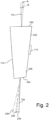
- the operating principle for filtering the input light 110 based on wavelength-dependent light diffraction is illustrated in Figure 2 showing the AOTF 112 alone.
- the AOTF 112 comprises a filter body 228 formed from a crystal such as tellurium dioxide (TeO 2 ) without being limited thereto.
- the filter body 228 has a light entrance surface 230 which is configured to receive the input light 110 within an angular acceptance range A.
- an arrow designated with reference sign 110 indicates a nominal direction of light incidence.
- the angular acceptance range A is defined by an angular tolerance ⁇ ⁇ by which the light incidence is allowed to deviate from the aforementioned nominal direction.
- the specific value of the angular tolerance ⁇ is predetermined in accordance with the specific filter design based on which the AOTF 112 is manufactured.
- the filter body 228 of the AOTF 112 comprises a transducer surface 232 on which the piezoelectric transducer 114 is attached. Further, the filter body 228 has a light emission surface 234 through which the spectrally filtered output light 126 is emitted from the AOTF 112.
- the optical filter function of the AOTF 112 can be easily changed by applying a suitable radio frequency (RF) signal to the transducer 114.
- RF radio frequency
- the control unit 118 shown in Figure 1 may determine the RF signal e.g. in response to a user input and apply the RF signal to the transducer 114. It is to be noted that the control unit 118 may simultaneously apply a plurality of RF signals to the transducer 114 so that the output light 126 comprises multiple wavelengths from the spectral bandwidth of the input light 110, each wavelength being assigned to one of the RF frequency signals applied to the transducer 114.
- Figure 2 illustrates a case where only one wavelength is selected from the broad spectral bandwidth provided by the input light 110.
- the input light 110 entering the filter body 228 through the light entrance surface 230 is unpolarized light.
- the output light 126 which is used for illuminating the sample 104 is given by a diffracted beam of first order having a specific polarization, e.g. horizontal (or vertical) polarization.
- a light beam 236 shown in Figure 2 represents a diffracted beam of first order having the other polarization, i.e. vertical (or horizontal) polarization.
- light beams to 238, 240 represent light beams which are not diffracted, i.e. beams of zero order having vertical and horizontal polarizations, respectively.
- the light beams 126, 236, 238, 240 are emitted from the AOTF 112 at different exit angles so that they are spatially separated from each other. Since only the output light 126 is used for illumination, the light beams to 236, 238, 240 may be absorbed by suitable means such as a light trap (not shown).
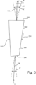
- Figure 3 also shows, as realized by the inventor, that satisfying the parallel-tangent condition in order to achieve the relatively large angular acceptance range A' may come at the expense of a relatively large angular spread C' among the multiple wavelengths of the output light 126 over the entire spectral bandwidth which is provided by the input light 110.
- the aforementioned angular spread C' is determined by the different exit angles at which the multiple wavelengths of the output light 126 are emitted from the light emission surface 334 of the AOTF 312. The greater the spectral bandwidth of the input light 110, the greater the angular spread C' of the output light 126, provided that the entire spectral bandwidth shall be usable.
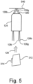
- FIG. 5 illustrates an example in which the output light 126 emitted from the AOTF 312 includes a red spectral component 126r, a green spectral component 126g, and a blue spectral component 126b. It shall be assumed that the different spectral components126r, 126g, 126b are directed into the illumination objective 124 having an exemplary magnification of 40.
- the filter design applied to the embodiments may provide for a reorientation of internal crystal angles slightly away from the parallel-tangent condition. For instance, by varying the angle of light incidence by 1°, the angle of the light entrance surface 230 by 1° and the angle of the transducer surface 232 by less than 0.1° from the respective ideal values of the reference filter design satisfying the parallel-tangent condition, an AOTF design can be achieved which has a significantly smaller angular spread C among the multiple wavelengths of the output light 126 as compared to the reference filter design. Surprisingly, small variations in the above filter parameters have been found to produce significant reductions of the angular spread C.
- filter parameters may also be selected such that they do not necessarily deviate the from parallel-tangent condition.
- strictly limiting the light entry to a collinear entry throughout the entire spectral bandwidth may give sufficient design freedom even within the parallel-tangent condition framework to achieve the desired angular characteristic with two or more wavelengths at the same exit angle.
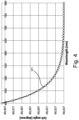
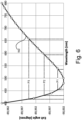
- Figure 6 is a graph showing an angular characteristic W2 according to an embodiment which is to be compared with the angular characteristic W1 of the conventional filter design shown in Figure 4 .
- the angular characteristic W2 according to the embodiment of Figure 6 varies from a minimum wavelength of 400 nm to a maximum wavelength of 800 nm.
- the entire variation of the angular characteristic W2 from 400 nm to 800 nm is less than 400 microradians which is a reduction in the angular spread by almost a factor of 4 compared to the conventional filter design of Figure 4 .
- the angular characteristic W2 has an extremum (minimum) at an intermediate wavelength which is in a range between 450 nm to 550 nm.
- the angular characteristic W1 of the conventional filter design shown in Figure 4 monotonically varies from the minimum wavelength to the maximum wavelength
- the angular characteristic W2 according to the embodiment shown in Figure 6 at first decreases from the minimum wavelength to the intermediate wavelength where the extremum of the characteristic W2 is located and then increases from the intermediate wavelength to the maximum wavelength. Accordingly, the new filter design deviates from a monotonically varying angular characteristic enabling the angular spread C to be reduced.
- Figure 7 is a graph showing an angular characteristic W3 according to another embodiment.
- the angular characteristic W3 varies from a minimum wavelength of 680 nm to a maximum wavelength of 1300 nm.
- the entire variation of the angular characteristic W3 is less than 60 microradians.
- the angular characteristic W3 has an extremum (maximum) at an intermediate wavelength which is in a range between 880 nm to 1080 nm. Accordingly, while the angular characteristic W1 of the conventional filter design shown in Figure 4 monotonically varies from the minimum wavelength to the maximum wavelength, the angular characteristic W3 at first increases from the minimum wavelength to the intermediate wavelength where the extremum of the characteristic W3 is located and then decreases from the intermediate wavelength to the maximum wavelength. Accordingly, the new filter design deviates from a monotonically varying angular characteristic which enables the angular spread C to be reduced.
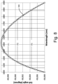
- Figure 8 is a graph showing an angular characteristic W4 according to another embodiment.
- the angular characteristic W4 varies from a minimum wavelength of 1000 nm to a maximum wavelength of 2000 nm.
- the entire variation of the angular characteristic W3 is less than 210 microradians.
- the angular characteristic W4 has an extremum (maximum) at an intermediate wavelength which is in a range between 1300 nm to 1500 nm. Accordingly, while the angular characteristic W1 of the conventional filter design shown in Figure 4 monotonically varies from the minimum wavelength to the maximum wavelength, the angular characteristic W3 at first increases from the minimum wavelength to the intermediate wavelength where the extremum of the characteristic W3 is located and then decreases from the intermediate wavelength to the maximum wavelength. Accordingly, the new filter design deviates from a monotonically varying angular characteristic which enables the angular spread C to be reduced.
- each of the angular characteristics W2 to W4 shown in Figures 6 to 8 have an extremum at an intermediate wavelength within a wavelength range where the AOTF 112 is operated. Therefore, each angular characteristic W2 to W4 provides a plurality of pairs P1, P2, P3, each pair including two wavelengths having the same exit angle when being emitted from the AOTF 112 as indicated in Figures 6 to 8 by dashed lines, respectively.
- FIG 9 shows the AOTF 112 when designed to implement one of the angular characteristics illustrated in Figures 6 to 8 .
- each group P1, P2 and P3 includes two wavelengths illustrated as solid and dashed lines, respectively, which are emitted from the AOTF 112 at the same exit angle.
- the angular characteristic enables the wavelengths of each group P1, P2, P3 to exit from the AOTF 112 in a perfectly collinear manner.
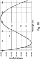
- Figure 10 is a graph showing an angular characteristic W5 according to another embodiment.
- the angular characteristic W5 of Figure 10 is an example where not only one extremum but several extrema are present.
- the angular characteristic W5 varies from a minimum wavelength of 580 nm to a maximum wavelength of 1100 nm.
- the angular characteristic W5 has a first extremum (minimum) at a first intermediate wavelength which is between 600 nm and 700 nm. Further, the angular characteristic W5 as a second extremum (maximum) at a second intermediate wavelength which is between 900 nm and 1000 nm. Accordingly, the characteristic W5 decreases from the minimum wavelength to the first intermediate wavelength and then increases from the first intermediate wavelength to the second intermediate wavelength. Finally, the angular characteristic W5 decreases from the second intermediate wavelength to the maximum wavelength.
- the angular characteristic W5 of Figure 10 has both a minimum and a maximum at the first and second intermediate wavelengths, respectively, the angular characteristic W5 provides a plurality of triples T1, T2, T3, each triple including three wavelengths having the same exit angle when being emitted from the AOTF 112 as indicated in Figure 10 by dashed lines.
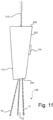
- FIG 11 shows the AOTF 112 when designed to implement the angular characteristic illustrated in Figure 10 .
- each triple T1, T2 and T3 includes three wavelengths illustrated as solid, dashed and dash-dotted lines, respectively, which are emitted from the AOTF 112 at the same exit angle. Accordingly, while there is still some angular spread among the multiple wavelengths of the output light 126 (albeit significantly reduced compared to the conventional filter design), the angular characteristic W5 ensures that the wavelengths of each group T1, T2, T3 exit from the AOTF 112 in a perfectly collinear manner.
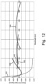
- Figure 12 is a graph showing the angular characteristics W1 to W5 described above in combination.
- the angular characteristics W2 to W5 which are based on the new filter design deviating from the parallel-tangent condition exhibit a significantly smaller angular spread compared to the conventional filter design which satisfies the parallel-tangent condition.
- the new filter design is suitable to cover a broad spectral bandwidth from 400 nm to 2000 nm including visible and near infrared light.
- control unit 118 may be configured to tune the AOTF 112 simultaneously to the wavelengths of one pair P1, P2, P3 or one triple T1, T2, T3 so that these wavelengths irradiate the target region of the sample 104 simultaneously.
- the control unit 118 may be further adapted to select one pair P1, P2, P3 or one triple T1, T2, T3 in response to a user input.
- the first and second light reflecting elements 120, 122 can be used to direct the output light 126 onto the sample 104.
- the first light reflecting element 120 may be actuated via the control unit 118 to deflect the respective group P1-P3, T1-T3 of different wavelengths into a predetermined target direction. This ensures that all groups P1-P3, T1-T3 propagate along the same direction towards the sample 104 despite the different exit angles at which they are emitted from the AOTF 112.
- the output light 126 may fall onto the second deflecting element 122 which is activated via the control unit 118 to deflect the output light 126 onto a predetermined target position on the sample 104.
- the second light reflecting element 122 may be formed from a scanning device which is configured to scan the sample 104 with the output light 126.
- the new filter design which enables two or three different wavelengths to be emitted from the AOTF 112 at the same exit angle can be used in applications which require multiple wavelengths be incident on the sample 104 at the same time and at the same location.
- One example is Coherent Anti-Stokes Raman (CARS) microscopy where two different wavelengths ⁇ 1 and ⁇ 2 are directed simultaneously towards the sample.
- CARS Coherent Anti-Stokes Raman
- ⁇ v designates the (vibrational) frequency difference
- ⁇ designates the unique exit angle at which the wavelengths ⁇ 1 and ⁇ 2 are emitted from the AOTF 112.
- the frequency difference corresponds to the energy of a vibrational mode in the sample under investigation.
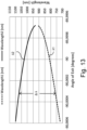
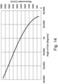
- Figures 13 and 14 illustrate how a suitable difference of wavelengths ⁇ 1 and ⁇ 2 can be selected to match a vibrational mode to be excited in a CARS experiment.
- Figure 13 shows wavelengths ⁇ 1 and ⁇ 2 which depend on a unique exit angle at which they are emitted from the AOTF 112.
- the difference of the inverse wavelengths 1/ ⁇ 1 - 1/ ⁇ 2 should match the vibrational mode to be excited which is represented in Figure 14 by a corresponding wavenumber.
- the vibrational mode depends on the exit angle at which the pair of wavelengths ⁇ 1, ⁇ 2 exit the AOTF 112. Accordingly, by selecting a suitable pair of wavelengths ⁇ 1, ⁇ 2 at a unique exit angle, a specific vibrational mode can be excited.
- the first light deflecting element 122 can then be used to redirect the pair of wavelengths at an appropriate angle towards the sample.
- any of the angular characteristics W2 to W4 as shown in Figures 6 to 8 can be applied as these angular characteristics allow to selectively create pairs of wavelengths which are emitted from the AOTF 112 at unique exit angles.
- the angular characteristic W5 of Figure 10 may be applied to perform an experiment in which it is required to illuminate the sample simultaneously with three different wavelengths ⁇ 1, ⁇ 2 and ⁇ 3 at the same exit angle.
- SRS Stimulated Raman Scattering
- FM-SRS Frequency-Modulated Stimulated Raman Scattering
- FM-SRS over the amplitude-modulated SRS version is that the intensity of the laser fields at the sample remains constant. This helps to avoid other undesired non-linear effects such as cross-phase modulation from being detected along with SRS.
- three wavelengths ⁇ 1, ⁇ 2 and ⁇ 3 can be selected at the same exit angle ⁇ such that the wavelengths ⁇ 1, ⁇ 2 and ⁇ 3 are spaced apart by predetermined frequency differences ⁇ v 12 and ⁇ v 23 according to following relationships: ⁇ 12 ⁇ ⁇ 1 ⁇ 1 ⁇ ⁇ 1 ⁇ 2 ⁇ ⁇ 23 ⁇ ⁇ 1 ⁇ 2 ⁇ ⁇ 1 ⁇ 3 ⁇
- the new filter design is not limited to the above applications. For instance, generating two or three output wavelengths which are emitted from the AOTF in a perfectly collinear manner may also be useful for instance in Sum-Frequency Generation (SFG) microscopy and Difference-Frequency Generation (DFG) microscopy.
- FSG Sum-Frequency Generation
- DFG Difference-Frequency Generation
- aspects have been described in the context of an apparatus, it is clear that these aspects also represent a description of the corresponding method, where a block or device corresponds to a method step or a feature of a method step. Analogously, aspects described in the context of a method step also represent a description of a corresponding block or item or feature of a corresponding apparatus.
Landscapes
- Physics & Mathematics (AREA)
- General Physics & Mathematics (AREA)
- Optics & Photonics (AREA)
- Chemical & Material Sciences (AREA)
- Analytical Chemistry (AREA)
- Nonlinear Science (AREA)
- Engineering & Computer Science (AREA)
- Computer Vision & Pattern Recognition (AREA)
- General Engineering & Computer Science (AREA)
- Spectroscopy & Molecular Physics (AREA)
- Microscoopes, Condenser (AREA)
Claims (14)
- Optische Filtervorrichtung (102) zur Beleuchtung einer Probe (104), umfassend eine Lichtversorgungseinheit (108), die so konfiguriert ist, dass sie Eingangslicht (110) mit einer vorbestimmten spektralen Bandbreite erzeugt,ein akusto-optisches abstimmbares Filter (112), das so konfiguriert ist, dass es das Eingangslicht (110) empfängt und gebeugtes Ausgangslicht (126) einschließlich mehrerer Wellenlängen aus der spektralen Bandbreite unter Austrittswinkeln in Richtung der Probe (104) emittiert, wobei die Austrittswinkel eine Winkelspreizung (C) zwischen den mehreren Wellenlängen des Ausgangslichts (126) definieren,wobei die Winkelspreizung (C) zwischen den mehreren Wellenlängen des Ausgangslichts (126) durch eine Winkelcharakteristik (W2-W5) bestimmt wird, die von einer minimalen Wellenlänge zu einer maximalen Wellenlänge variiert und angibt, wie die Austrittswinkel in Abhängigkeit von den Wellenlängen variieren,dadurch gekennzeichnet, dass die Lichtversorgungseinheit (108) so konfiguriert ist, dass sie das Eingangslicht (110) der vorbestimmten spektralen Bandbreite in einer kollinearen Weise erzeugt, undwobei die Winkelcharakteristik (W2-W5) ein Extremum bei einer Zwischenwellenlänge zwischen der minimalen Wellenlänge und der maximalen Wellenlänge aufweist, um mindestens eine Gruppe (P1-P3, T1-T3) von verschiedenen Wellenlängen mit demselben Austrittswinkel bereitzustellen.
- Optische Filtervorrichtung (102) nach Anspruch 1, wobei die mindestens eine Gruppe ein Paar (P1-P3) verschiedener Wellenlängen oder ein Tripel (T1-T3) verschiedener Wellenlängen ist.
- Optische Filtervorrichtung (102) nach Anspruch 1 oder 2, wobei die mindestens eine Gruppe (P1-P3, T1-T3) eine Vielzahl von Gruppen einschließt, wobei jede Gruppe einem aus einer Vielzahl von verschiedenen Austrittswinkeln zugeordnet ist.
- Optische Filtervorrichtung (102) nach einem der vorstehenden Ansprüche, umfassend eine Steuereinheit (118), die so konfiguriert ist, dass sie das akusto-optische abstimmbare Filter (112) so abstimmt, dass die Probe (104) mit der mindestens einen Gruppe (P1-P3, T1-T3) verschiedener Wellenlängen bei demselben Austrittswinkel beleuchtet wird.
- Optische Filtervorrichtung (102) nach einem der vorstehenden Ansprüche, wobei die Steuereinheit (118) so konfiguriert ist, dass sie die mindestens eine Gruppe (P1-P3, T1-T3) verschiedener Wellenlängen auf der Grundlage der Winkelcharakteristik (W2-W5) in Reaktion auf eine Benutzereingabe auswählt.
- Optische Filtervorrichtung (102) nach Anspruch 4 oder 5, wobei die Steuereinheit (118) so konfiguriert ist, dass sie das akusto-optische abstimmbare Filter (112) gleichzeitig auf die verschiedenen Wellenlängen der mindestens einen Gruppe (P1-P3, T1-T3) abstimmt.
- Optische Filtervorrichtung (102) nach einem der vorstehenden Ansprüche, umfassend ein erstes Lichtablenkungselement (120), das so konfiguriert ist, dass es die mindestens eine Gruppe (P1-P3, T1-T3) verschiedener Wellenlängen, die von dem akusto-optischen abstimmbaren Filter (112) ausgegeben werden, in eine vorbestimmte Zielrichtung ablenkt.
- Optische Filtervorrichtung (102) nach Anspruch 7, umfassend einen Speicher (119), der so konfiguriert ist, dass er Kalibrierungsdaten speichert, die einen Betrag zur Betätigung des ersten Lichtablenkungselements (120) in Abhängigkeit von dem Austrittswinkel, der der mindestens einen Gruppe (P1-P3, T1-T3) verschiedener Wellenlängen zugeordnet ist, darstellen, um die Gruppe (P1-P3, T1-T3) in die vorbestimmte Zielrichtung abzulenken, wobei die Steuereinheit (118) so konfiguriert ist, dass sie das erste Lichtablenkungselement (120) auf der Grundlage der Kalibrierungsdaten steuert.
- Optische Filtervorrichtung (102) nach Anspruch 7 oder 8, umfassend ein zweites Lichtablenkungselement (122), das so konfiguriert ist, dass es die mindestens eine Gruppe (P1-P3, T1-T3) verschiedener Wellenlängen, die von dem akusto-optischen abstimmbaren Filter (112) ausgegeben werden, auf eine vorbestimmte Zielposition auf der Probe (104) ablenkt.
- Optische Filtervorrichtung (102) nach einem der vorstehenden Ansprüche, umfassend ein Beleuchtungsobjektiv (124), das so konfiguriert ist, dass es die Probe (104) mit dem von dem akusto-optischen abstimmbaren Filter (112) emittierten Ausgangslicht (126) beleuchtet.
- Optische Filtervorrichtung (102) nach einem der vorstehenden Ansprüche, wobei die Lichtversorgungseinheit (108) eine Superkontinuum-Laserquelle umfasst.
- Mikroskop (100), insbesondere ein konfokales Mikroskop, ein Multiphotonenmikroskop, ein Kohärente Anti-Stokes-Raman- (CARS) Mikroskop, ein Stimulierte Raman-Streuung- (SRS) Mikroskop, ein Summen-Frequenz-Erzeugungs-(SFG) Mikroskop, ein Differenz-Frequenz-Erzeugungs- (DFG) Mikroskop und/oder ein Frequenzmodulierte Stimulierte Raman-Streuung- (FM-SRS) Mikroskop, umfassend die optische Filtervorrichtung (102) nach einem der vorstehenden Ansprüche.
- Verfahren zur Beleuchtung einer Probe (104), umfassend die folgenden Schritte:Erzeugen von Eingangslicht (110) einer vorbestimmten spektralen Bandbreite,Verwenden eines akusto-optischen abstimmbaren Filters (112) zum Empfangen des Eingangslichts (110) und Emittieren von gebeugtem Ausgangslicht (126) einschließlich mehrerer Wellenlängen aus der spektralen Bandbreite unter Austrittswinkeln in Richtung der Probe, wobei die Austrittswinkel eine Winkelspreizung zwischen den mehreren Wellenlängen des Ausgangslichts (126) definieren,wobei die Winkelspreizung (C) zwischen den mehreren Wellenlängen des Ausgangslichts (126) durch eine Winkelcharakteristik (W2-W5) bestimmt wird, die von einer minimalen Wellenlänge zu einer maximalen Wellenlänge variiert und angibt, wie die Austrittswinkel in Abhängigkeit von den Wellenlängen variieren,dadurch gekennzeichnet, dass das Eingangslicht (110) mit der vorbestimmten spektralen Bandbreite in einer kollinearen Weise erzeugt wird,wobei die Winkelcharakteristik (W2-W5) mindestens eine Gruppe (P1-P3, T1-T3) verschiedener Wellenlängen mit demselben Austrittswinkel bereitstellt, undwobei die Winkelcharakteristik (W2-W5) ein Extremum bei einer Zwischenwellenlänge zwischen der minimalen Wellenlänge und der maximalen Wellenlänge aufweist.
- Verfahren nach Anspruch 13, wobei die Probe (104) mit dem von dem akusto-optischen abstimmbaren Filter (112) emittierten Ausgangslicht beleuchtet wird, um konfokale Mikroskopie, Multiphotonenmikroskopie, kohärente Anti-Stokes-Raman-(CARS) Mikroskopie, Stimulierte Raman-Streuung- (SRS) Mikroskopie, SummenFrequenz-Erzeugungs- (SFG) Mikroskopie, Differenz-Frequenz-Erzeugungs- (DFG) Mikroskopie und/oder Frequenzmodulierte stimulierte Raman-Streuung- (FM-SRS) Mikroskopie durchzuführen.
Priority Applications (1)
| Application Number | Priority Date | Filing Date | Title |
|---|---|---|---|
| EP21194934.2A EP4145207B1 (de) | 2021-09-03 | 2021-09-03 | Optische filtervorrichtung zur beleuchtung einer probe |
Applications Claiming Priority (1)
| Application Number | Priority Date | Filing Date | Title |
|---|---|---|---|
| EP21194934.2A EP4145207B1 (de) | 2021-09-03 | 2021-09-03 | Optische filtervorrichtung zur beleuchtung einer probe |
Publications (2)
| Publication Number | Publication Date |
|---|---|
| EP4145207A1 EP4145207A1 (de) | 2023-03-08 |
| EP4145207B1 true EP4145207B1 (de) | 2025-07-09 |
Family
ID=77640523
Family Applications (1)
| Application Number | Title | Priority Date | Filing Date |
|---|---|---|---|
| EP21194934.2A Active EP4145207B1 (de) | 2021-09-03 | 2021-09-03 | Optische filtervorrichtung zur beleuchtung einer probe |
Country Status (1)
| Country | Link |
|---|---|
| EP (1) | EP4145207B1 (de) |
Family Cites Families (2)
| Publication number | Priority date | Publication date | Assignee | Title |
|---|---|---|---|---|
| CN111630432B (zh) * | 2018-01-15 | 2023-11-28 | 莱卡微系统Cms有限责任公司 | 声光的装置和方法 |
| DE102018110083A1 (de) * | 2018-04-26 | 2019-10-31 | Carl Zeiss Microscopy Gmbh | Optikanordnung zur flexiblen Mehrfarbbeleuchtung für ein Lichtmikroskop und Verfahren hierzu |
-
2021
- 2021-09-03 EP EP21194934.2A patent/EP4145207B1/de active Active
Also Published As
| Publication number | Publication date |
|---|---|
| EP4145207A1 (de) | 2023-03-08 |
Similar Documents
| Publication | Publication Date | Title |
|---|---|---|
| Wachman et al. | Imaging acousto-optic tunable filter with 0.35-micrometer spatial resolution | |
| US7133130B2 (en) | Method for scanning microscopy, scanning microscope, and apparatus for coding an illuminating light beam | |
| JP6538694B2 (ja) | 走査顕微鏡及び該走査顕微鏡のための音響光学メインビームスプリッタ | |
| JP6530405B2 (ja) | ビームコンバイナ、音響光学ビームコンバイナ、光源、顕微鏡及び使用 | |
| US5796512A (en) | Subicron imaging system having an acousto-optic tunable filter | |
| US10310243B2 (en) | Device and method for multispot scanning microscopy | |
| US8718414B2 (en) | Acousto-optical tunable filter element | |
| EP2597438A1 (de) | Stimulierte Ramanstreuungs-Messvorrichtung | |
| WO2010055735A1 (ja) | テラヘルツ波発生装置 | |
| US10132682B2 (en) | Microscope with an acousto-optical device | |
| EP3193207B1 (de) | Lichtbestrahlungsvorrichtung und lichtbestrahlungsverfahren | |
| US20200166457A1 (en) | Measurement device and irradiation device | |
| JP6632531B2 (ja) | 照明光の焦点の形状を変える部材を有する顕微鏡 | |
| EP4145207B1 (de) | Optische filtervorrichtung zur beleuchtung einer probe | |
| Gupta et al. | Notch filtering using a multiple passband AOTF in the SWIR region | |
| EP4145218B1 (de) | Optische filtervorrichtung | |
| EP1192431A1 (de) | Vorrichtung zur messung der fluorescenz | |
| Rietdorf et al. | Special optical elements | |
| EP4196835B1 (de) | Strahlteilungsvorrichtung | |
| US20070081214A1 (en) | Image scanning apparatus | |
| Voloshinov et al. | Tunable acousto-optic filters and their applications in laser technology, optical communication, and processing of images | |
| WO2025214596A1 (en) | Acousto-optic system and optical device | |
| HK1038797B (en) | Arrangement for separation excitation light and emission light in a microscope | |
| Paulsen et al. | Electronically tunable narrow-bandpass optical filter for spectral imaging | |
| HK1038797A1 (en) | Arrangement for separation excitation light and emission light in a microscope |
Legal Events
| Date | Code | Title | Description |
|---|---|---|---|
| PUAI | Public reference made under article 153(3) epc to a published international application that has entered the european phase |
Free format text: ORIGINAL CODE: 0009012 |
|
| STAA | Information on the status of an ep patent application or granted ep patent |
Free format text: STATUS: THE APPLICATION HAS BEEN PUBLISHED |
|
| AK | Designated contracting states |
Kind code of ref document: A1 Designated state(s): AL AT BE BG CH CY CZ DE DK EE ES FI FR GB GR HR HU IE IS IT LI LT LU LV MC MK MT NL NO PL PT RO RS SE SI SK SM TR |
|
| P01 | Opt-out of the competence of the unified patent court (upc) registered |
Effective date: 20230414 |
|
| STAA | Information on the status of an ep patent application or granted ep patent |
Free format text: STATUS: REQUEST FOR EXAMINATION WAS MADE |
|
| 17P | Request for examination filed |
Effective date: 20230908 |
|
| RBV | Designated contracting states (corrected) |
Designated state(s): AL AT BE BG CH CY CZ DE DK EE ES FI FR GB GR HR HU IE IS IT LI LT LU LV MC MK MT NL NO PL PT RO RS SE SI SK SM TR |
|
| GRAP | Despatch of communication of intention to grant a patent |
Free format text: ORIGINAL CODE: EPIDOSNIGR1 |
|
| STAA | Information on the status of an ep patent application or granted ep patent |
Free format text: STATUS: GRANT OF PATENT IS INTENDED |
|
| INTG | Intention to grant announced |
Effective date: 20250214 |
|
| GRAS | Grant fee paid |
Free format text: ORIGINAL CODE: EPIDOSNIGR3 |
|
| GRAA | (expected) grant |
Free format text: ORIGINAL CODE: 0009210 |
|
| STAA | Information on the status of an ep patent application or granted ep patent |
Free format text: STATUS: THE PATENT HAS BEEN GRANTED |
|
| AK | Designated contracting states |
Kind code of ref document: B1 Designated state(s): AL AT BE BG CH CY CZ DE DK EE ES FI FR GB GR HR HU IE IS IT LI LT LU LV MC MK MT NL NO PL PT RO RS SE SI SK SM TR |
|
| REG | Reference to a national code |
Ref country code: GB Ref legal event code: FG4D |
|
| REG | Reference to a national code |
Ref country code: CH Ref legal event code: EP |
|
| REG | Reference to a national code |
Ref country code: IE Ref legal event code: FG4D |
|
| REG | Reference to a national code |
Ref country code: DE Ref legal event code: R096 Ref document number: 602021033672 Country of ref document: DE |
|
| PGFP | Annual fee paid to national office [announced via postgrant information from national office to epo] |
Ref country code: DE Payment date: 20250926 Year of fee payment: 5 |
|
| PGFP | Annual fee paid to national office [announced via postgrant information from national office to epo] |
Ref country code: GB Payment date: 20250923 Year of fee payment: 5 |
|
| PGFP | Annual fee paid to national office [announced via postgrant information from national office to epo] |
Ref country code: FR Payment date: 20250925 Year of fee payment: 5 Ref country code: AT Payment date: 20251020 Year of fee payment: 5 |
|
| REG | Reference to a national code |
Ref country code: NL Ref legal event code: MP Effective date: 20250709 |
|
| PG25 | Lapsed in a contracting state [announced via postgrant information from national office to epo] |
Ref country code: PT Free format text: LAPSE BECAUSE OF FAILURE TO SUBMIT A TRANSLATION OF THE DESCRIPTION OR TO PAY THE FEE WITHIN THE PRESCRIBED TIME-LIMIT Effective date: 20251110 |
|
| PG25 | Lapsed in a contracting state [announced via postgrant information from national office to epo] |
Ref country code: NL Free format text: LAPSE BECAUSE OF FAILURE TO SUBMIT A TRANSLATION OF THE DESCRIPTION OR TO PAY THE FEE WITHIN THE PRESCRIBED TIME-LIMIT Effective date: 20250709 |
|
| REG | Reference to a national code |
Ref country code: AT Ref legal event code: MK05 Ref document number: 1812345 Country of ref document: AT Kind code of ref document: T Effective date: 20250709 |