EP4145046A1 - Resin component for vehicle - Google Patents
Resin component for vehicle Download PDFInfo
- Publication number
- EP4145046A1 EP4145046A1 EP21797408.8A EP21797408A EP4145046A1 EP 4145046 A1 EP4145046 A1 EP 4145046A1 EP 21797408 A EP21797408 A EP 21797408A EP 4145046 A1 EP4145046 A1 EP 4145046A1
- Authority
- EP
- European Patent Office
- Prior art keywords
- lamp
- vehicle
- welding
- rear combination
- side rear
- Prior art date
- Legal status (The legal status is an assumption and is not a legal conclusion. Google has not performed a legal analysis and makes no representation as to the accuracy of the status listed.)
- Pending
Links
Images


Classifications
-
- F—MECHANICAL ENGINEERING; LIGHTING; HEATING; WEAPONS; BLASTING
- F21—LIGHTING
- F21S—NON-PORTABLE LIGHTING DEVICES; SYSTEMS THEREOF; VEHICLE LIGHTING DEVICES SPECIALLY ADAPTED FOR VEHICLE EXTERIORS
- F21S43/00—Signalling devices specially adapted for vehicle exteriors, e.g. brake lamps, direction indicator lights or reversing lights
- F21S43/20—Signalling devices specially adapted for vehicle exteriors, e.g. brake lamps, direction indicator lights or reversing lights characterised by refractors, transparent cover plates, light guides or filters
- F21S43/27—Attachment thereof
-
- B—PERFORMING OPERATIONS; TRANSPORTING
- B29—WORKING OF PLASTICS; WORKING OF SUBSTANCES IN A PLASTIC STATE IN GENERAL
- B29C—SHAPING OR JOINING OF PLASTICS; SHAPING OF MATERIAL IN A PLASTIC STATE, NOT OTHERWISE PROVIDED FOR; AFTER-TREATMENT OF THE SHAPED PRODUCTS, e.g. REPAIRING
- B29C65/00—Joining or sealing of preformed parts, e.g. welding of plastics materials; Apparatus therefor
- B29C65/02—Joining or sealing of preformed parts, e.g. welding of plastics materials; Apparatus therefor by heating, with or without pressure
- B29C65/022—Particular heating or welding methods not otherwise provided for
-
- B—PERFORMING OPERATIONS; TRANSPORTING
- B29—WORKING OF PLASTICS; WORKING OF SUBSTANCES IN A PLASTIC STATE IN GENERAL
- B29C—SHAPING OR JOINING OF PLASTICS; SHAPING OF MATERIAL IN A PLASTIC STATE, NOT OTHERWISE PROVIDED FOR; AFTER-TREATMENT OF THE SHAPED PRODUCTS, e.g. REPAIRING
- B29C65/00—Joining or sealing of preformed parts, e.g. welding of plastics materials; Apparatus therefor
- B29C65/02—Joining or sealing of preformed parts, e.g. welding of plastics materials; Apparatus therefor by heating, with or without pressure
- B29C65/18—Joining or sealing of preformed parts, e.g. welding of plastics materials; Apparatus therefor by heating, with or without pressure using heated tools
- B29C65/20—Joining or sealing of preformed parts, e.g. welding of plastics materials; Apparatus therefor by heating, with or without pressure using heated tools with direct contact, e.g. using "mirror"
-
- B—PERFORMING OPERATIONS; TRANSPORTING
- B29—WORKING OF PLASTICS; WORKING OF SUBSTANCES IN A PLASTIC STATE IN GENERAL
- B29C—SHAPING OR JOINING OF PLASTICS; SHAPING OF MATERIAL IN A PLASTIC STATE, NOT OTHERWISE PROVIDED FOR; AFTER-TREATMENT OF THE SHAPED PRODUCTS, e.g. REPAIRING
- B29C66/00—General aspects of processes or apparatus for joining preformed parts
- B29C66/01—General aspects dealing with the joint area or with the area to be joined
- B29C66/05—Particular design of joint configurations
- B29C66/10—Particular design of joint configurations particular design of the joint cross-sections
- B29C66/11—Joint cross-sections comprising a single joint-segment, i.e. one of the parts to be joined comprising a single joint-segment in the joint cross-section
- B29C66/112—Single lapped joints
-
- B—PERFORMING OPERATIONS; TRANSPORTING
- B29—WORKING OF PLASTICS; WORKING OF SUBSTANCES IN A PLASTIC STATE IN GENERAL
- B29C—SHAPING OR JOINING OF PLASTICS; SHAPING OF MATERIAL IN A PLASTIC STATE, NOT OTHERWISE PROVIDED FOR; AFTER-TREATMENT OF THE SHAPED PRODUCTS, e.g. REPAIRING
- B29C66/00—General aspects of processes or apparatus for joining preformed parts
- B29C66/01—General aspects dealing with the joint area or with the area to be joined
- B29C66/05—Particular design of joint configurations
- B29C66/10—Particular design of joint configurations particular design of the joint cross-sections
- B29C66/11—Joint cross-sections comprising a single joint-segment, i.e. one of the parts to be joined comprising a single joint-segment in the joint cross-section
- B29C66/114—Single butt joints
-
- B—PERFORMING OPERATIONS; TRANSPORTING
- B29—WORKING OF PLASTICS; WORKING OF SUBSTANCES IN A PLASTIC STATE IN GENERAL
- B29C—SHAPING OR JOINING OF PLASTICS; SHAPING OF MATERIAL IN A PLASTIC STATE, NOT OTHERWISE PROVIDED FOR; AFTER-TREATMENT OF THE SHAPED PRODUCTS, e.g. REPAIRING
- B29C66/00—General aspects of processes or apparatus for joining preformed parts
- B29C66/01—General aspects dealing with the joint area or with the area to be joined
- B29C66/05—Particular design of joint configurations
- B29C66/301—Three-dimensional joints, i.e. the joined area being substantially non-flat
-
- B—PERFORMING OPERATIONS; TRANSPORTING
- B29—WORKING OF PLASTICS; WORKING OF SUBSTANCES IN A PLASTIC STATE IN GENERAL
- B29C—SHAPING OR JOINING OF PLASTICS; SHAPING OF MATERIAL IN A PLASTIC STATE, NOT OTHERWISE PROVIDED FOR; AFTER-TREATMENT OF THE SHAPED PRODUCTS, e.g. REPAIRING
- B29C66/00—General aspects of processes or apparatus for joining preformed parts
- B29C66/50—General aspects of joining tubular articles; General aspects of joining long products, i.e. bars or profiled elements; General aspects of joining single elements to tubular articles, hollow articles or bars; General aspects of joining several hollow-preforms to form hollow or tubular articles
- B29C66/51—Joining tubular articles, profiled elements or bars; Joining single elements to tubular articles, hollow articles or bars; Joining several hollow-preforms to form hollow or tubular articles
- B29C66/54—Joining several hollow-preforms, e.g. half-shells, to form hollow articles, e.g. for making balls, containers; Joining several hollow-preforms, e.g. half-cylinders, to form tubular articles
-
- B—PERFORMING OPERATIONS; TRANSPORTING
- B60—VEHICLES IN GENERAL
- B60Q—ARRANGEMENT OF SIGNALLING OR LIGHTING DEVICES, THE MOUNTING OR SUPPORTING THEREOF OR CIRCUITS THEREFOR, FOR VEHICLES IN GENERAL
- B60Q1/00—Arrangement of optical signalling or lighting devices, the mounting or supporting thereof or circuits therefor
- B60Q1/26—Arrangement of optical signalling or lighting devices, the mounting or supporting thereof or circuits therefor the devices being primarily intended to indicate the vehicle, or parts thereof, or to give signals, to other traffic
- B60Q1/30—Arrangement of optical signalling or lighting devices, the mounting or supporting thereof or circuits therefor the devices being primarily intended to indicate the vehicle, or parts thereof, or to give signals, to other traffic for indicating rear of vehicle, e.g. by means of reflecting surfaces
- B60Q1/304—Adaptations of signalling devices having a part on the vehicle body and another on the boot door
-
- F—MECHANICAL ENGINEERING; LIGHTING; HEATING; WEAPONS; BLASTING
- F21—LIGHTING
- F21S—NON-PORTABLE LIGHTING DEVICES; SYSTEMS THEREOF; VEHICLE LIGHTING DEVICES SPECIALLY ADAPTED FOR VEHICLE EXTERIORS
- F21S43/00—Signalling devices specially adapted for vehicle exteriors, e.g. brake lamps, direction indicator lights or reversing lights
- F21S43/20—Signalling devices specially adapted for vehicle exteriors, e.g. brake lamps, direction indicator lights or reversing lights characterised by refractors, transparent cover plates, light guides or filters
- F21S43/26—Refractors, transparent cover plates, light guides or filters not provided in groups F21S43/235 - F21S43/255
-
- B—PERFORMING OPERATIONS; TRANSPORTING
- B29—WORKING OF PLASTICS; WORKING OF SUBSTANCES IN A PLASTIC STATE IN GENERAL
- B29C—SHAPING OR JOINING OF PLASTICS; SHAPING OF MATERIAL IN A PLASTIC STATE, NOT OTHERWISE PROVIDED FOR; AFTER-TREATMENT OF THE SHAPED PRODUCTS, e.g. REPAIRING
- B29C65/00—Joining or sealing of preformed parts, e.g. welding of plastics materials; Apparatus therefor
- B29C65/02—Joining or sealing of preformed parts, e.g. welding of plastics materials; Apparatus therefor by heating, with or without pressure
- B29C65/06—Joining or sealing of preformed parts, e.g. welding of plastics materials; Apparatus therefor by heating, with or without pressure using friction, e.g. spin welding
-
- B—PERFORMING OPERATIONS; TRANSPORTING
- B29—WORKING OF PLASTICS; WORKING OF SUBSTANCES IN A PLASTIC STATE IN GENERAL
- B29C—SHAPING OR JOINING OF PLASTICS; SHAPING OF MATERIAL IN A PLASTIC STATE, NOT OTHERWISE PROVIDED FOR; AFTER-TREATMENT OF THE SHAPED PRODUCTS, e.g. REPAIRING
- B29C65/00—Joining or sealing of preformed parts, e.g. welding of plastics materials; Apparatus therefor
- B29C65/02—Joining or sealing of preformed parts, e.g. welding of plastics materials; Apparatus therefor by heating, with or without pressure
- B29C65/14—Joining or sealing of preformed parts, e.g. welding of plastics materials; Apparatus therefor by heating, with or without pressure using wave energy, i.e. electromagnetic radiation, or particle radiation
- B29C65/1429—Joining or sealing of preformed parts, e.g. welding of plastics materials; Apparatus therefor by heating, with or without pressure using wave energy, i.e. electromagnetic radiation, or particle radiation characterised by the way of heating the interface
- B29C65/1432—Joining or sealing of preformed parts, e.g. welding of plastics materials; Apparatus therefor by heating, with or without pressure using wave energy, i.e. electromagnetic radiation, or particle radiation characterised by the way of heating the interface direct heating of the surfaces to be joined
-
- B—PERFORMING OPERATIONS; TRANSPORTING
- B29—WORKING OF PLASTICS; WORKING OF SUBSTANCES IN A PLASTIC STATE IN GENERAL
- B29C—SHAPING OR JOINING OF PLASTICS; SHAPING OF MATERIAL IN A PLASTIC STATE, NOT OTHERWISE PROVIDED FOR; AFTER-TREATMENT OF THE SHAPED PRODUCTS, e.g. REPAIRING
- B29C66/00—General aspects of processes or apparatus for joining preformed parts
- B29C66/70—General aspects of processes or apparatus for joining preformed parts characterised by the composition, physical properties or the structure of the material of the parts to be joined; Joining with non-plastics material
- B29C66/71—General aspects of processes or apparatus for joining preformed parts characterised by the composition, physical properties or the structure of the material of the parts to be joined; Joining with non-plastics material characterised by the composition of the plastics material of the parts to be joined
- B29C66/712—General aspects of processes or apparatus for joining preformed parts characterised by the composition, physical properties or the structure of the material of the parts to be joined; Joining with non-plastics material characterised by the composition of the plastics material of the parts to be joined the composition of one of the parts to be joined being different from the composition of the other part
-
- B—PERFORMING OPERATIONS; TRANSPORTING
- B29—WORKING OF PLASTICS; WORKING OF SUBSTANCES IN A PLASTIC STATE IN GENERAL
- B29L—INDEXING SCHEME ASSOCIATED WITH SUBCLASS B29C, RELATING TO PARTICULAR ARTICLES
- B29L2011/00—Optical elements, e.g. lenses, prisms
- B29L2011/0016—Lenses
-
- B—PERFORMING OPERATIONS; TRANSPORTING
- B29—WORKING OF PLASTICS; WORKING OF SUBSTANCES IN A PLASTIC STATE IN GENERAL
- B29L—INDEXING SCHEME ASSOCIATED WITH SUBCLASS B29C, RELATING TO PARTICULAR ARTICLES
- B29L2031/00—Other particular articles
- B29L2031/30—Vehicles, e.g. ships or aircraft, or body parts thereof
- B29L2031/3055—Cars
-
- B—PERFORMING OPERATIONS; TRANSPORTING
- B29—WORKING OF PLASTICS; WORKING OF SUBSTANCES IN A PLASTIC STATE IN GENERAL
- B29L—INDEXING SCHEME ASSOCIATED WITH SUBCLASS B29C, RELATING TO PARTICULAR ARTICLES
- B29L2031/00—Other particular articles
- B29L2031/747—Lightning equipment
Definitions
- the present invention relates to a resin component for vehicle.
- Patent Literature 1 there is a vehicle resin component in which a first resin member and a second resin member are fixed by welding under pressure, as shown in Patent Literature 1.
- Patent Literature 1 The following is a description of the Patent Literature 1.
- a vehicle lamp of the Patent Literature 1 is the one in which a convex portion of a translucent cover as the first resin member and a rib of a lamp body as the second resin member are fixed by vibration welding under pressure.
- the vehicle lamp of the Patent Literature 1 can ensure a required bond strength at a low cost and without loss of design, even when the translucent cover is so formed as to extend along a curved surface shape.
- the problem to be solved by the present invention is to provide a vehicle resin component that can secure a required weld strength even when the shape of a first resin member is formed in a desired design shape.
- a vehicle resin component of the present invention includes: a first resin member; and a second resin member, wherein the first resin member and the second resin member are fixed by welding under pressure, the first resin member has a body portion, a leg portion provided on the body portion inclined toward the body portion side relative to a direction of the welding under pressure, and a welding portion that is provided on the leg portion in a manner to be bent toward an opposite side of the body portion relative to an inclination direction of the leg portion and that is welded to the first resin member under pressure.
- the first resin member is a lamp lens
- the second resin member is a lamp housing
- the leg portion of the lamp lens is inclined relative to a front view direction in a manner to overlap, in the front view direction, with the lamp lens of a vehicle lamp adjacently mounted on a vehicle.
- the first resin member is a lamp lens
- the second resin member is a lamp housing
- the body portion of the lamp lens and the lamp housing have wrap-around portions that wrap around to the leg portion side of the lamp lens.
- a vehicle resin component of the present invention can ensure a required weld strength even when the shape of a first resin member is formed in the desired design shape.
- front, rear, top, bottom, left, and right are front, rear, top, bottom, left, and right seen when the vehicle resin component (vehicle lamp) of the present invention is provided on a vehicle V.
- FIGS. 1 to 5 show a first embodiment of a vehicle resin component according to the present invention.
- the following is a description of a configuration of the vehicle resin component according to this first embodiment.
- a reference sign 1C represents the vehicle resin component according to this first embodiment (hereinafter simply referred to as "vehicle resin component").
- the vehicle resin component 1C is a vehicle lamp, in this example a center-side rear combination lamp, as shown in FIG. 1 .
- the vehicle resin component 1C is hereafter referred to as a center-side rear combination lamp 1C.
- the center-side rear combination lamp 1C is provided in the center portion in the rear portion of the vehicle V, in this example, on a movable-side back door.
- the vehicle resin component 1C is provided over most of the entire width direction (right/left direction) of the vehicle V.
- Left and right side portions in the rear portion of the vehicle V, in this example, the fixed-side vehicle body, are provided with a left-side rear combination lamp 1L as a vehicle lamp, and also a right-side rear combination lamp 1R as a vehicle lamp, respectively.
- the center-side rear combination lamp 1C, the left-side rear combination lamp 1L, and the right-side rear combination lamp 1R constitute a vehicle lamp with a sense of unity (connectedness) over the entire width direction (right/left direction) of the vehicle V, i.e., a rear combination lamp.
- the center-side rear combination lamp 1C as shown in FIGS. 1 , 2 , 3A , and 4 , has a lamp lens 2 as a first resin member and a lamp housing 3 as a second resin member.
- the lamp lens 2 and the lamp housing 3 are fixed to each other by welding under pressure (i.e., hot plate welding).
- the lamp lens 2 and the lamp housing 3 form a lamp chamber 4.
- the lamp unit has a light source (not shown).
- the lamp units include, for example, tail lamps, stop lamps, turn signal lamps, and back lamps.
- the lamp lens 2 in this example, is made of light-transmitting resin (e.g., acrylic).
- the lamp lens 2 has a body portion 20, a leg portion 21, and a welding portion 22.
- the body portion 20 is plate-shaped having a plate thickness (wall thickness) of, in this example, about 1.0 mm to about 3.0 mm.
- the body portion 20 has a front view shape (viewing the front side from the rear side of the vehicle V) that is a long rectangular in shape in the transverse (right/left) direction.
- the thickness (wall thickness) of the body portion 20, relative to a diameter of an ejector pin, requires, in this example, a minimum of about 1.0 mm.
- the leg portion 21 is inclined (bent) from the entire peripheral edge portion of the body portion 20 to the lamp housing 3 side (from the rear side to the front side of the vehicle V) and is integrally provided.
- the leg portion 21 is provided on the body portion 20 in a manner to be inclined to the body portion 20 side at an angle ⁇ 1 relative to a direction P of the welding under pressure.
- the angle ⁇ 1 is from about 45° to about 60° in this example.
- the leg portion 21 is inclined relative to the front view direction in a manner to overlap, in the front view direction (the front-rear direction of the vehicle V), with a lamp lens 2L of the left-side rear combination lamp 1L adjacently mounted on the vehicle V.
- This front view direction is substantially the same as, i.e., substantially parallel to the direction P of the welding under pressure described above.
- the welding portion 22 is bent from the leg portion 21's tip (opposite end to the end on the body portion 20 side) in the opposite direction of the direction of bending the leg portion 21 and is integrally provided.
- the welding portion 22 is provided at the leg portion 21 in a manner to be inclined at an angle ⁇ 2 relative to the inclination direction of the leg portion 21, opposite to the body portion 20.
- the angle ⁇ 2 is, in this example, from about 20° to the above angle ⁇ 1.
- a length T1 between the leg portion 21 and the welding portion 22 is, in this example, about 10 mm or more.
- the length T1 between the leg portion 21 and the welding portion 22 is a length of the leg portion 21 in the inclination direction from the body portion 20 to the lamp housing 3.
- a length T2 of the welding portion 22 is, in this example, about 1.0 mm or more.
- the length T2 of the welding portion 22 is a length of the welding portion 22 in the centerline direction from an edge portion bent with the leg portion 21 to the lamp housing 3.
- the lamp housing 3 in this example, is made of light-non-transmitting resin (such as ABS resin).
- the lamp housing 3 has a body portion 30, a welding portion 31, and a convex portion 32.
- the body portion 30, like the body portion 20 of the lamp lens 2, is plate-shaped, and has a front view shape that is a long rectangular shape in the transverse direction.
- the welding portion 31 is integrally provided in a portion slightly closer to the center side from the entire peripheral edge portion of the body portion 30.
- the front face of the welding portion 31 is flush with the front face of the body portion 30.
- the convex portion 32 is so provided as to integrally protrude from the entire peripheral edge portion of the body portion 30 toward the lamp lens 2 side (from the front of the vehicle V to the rear).
- the lamp lens 2 and the lamp housing 3 are each stored and held in a jig by a suction pad or the like (not shown).
- the welding portion 22 of the lamp lens 2 and the welding portion 31 of the lamp housing 3 are softened by a heating plate (heating block) not shown in the drawing.
- the welding portion 22 of the lamp lens 2 and the welding portion 31 of the lamp housing 3 may be in contact or non-contact with the heating block.
- the welding portion 22 of the lamp lens 2 is pressed onto the welding portion 31 of the lamp housing 3 in the solid arrow direction P in FIG. 2 .
- This pressing direction P is perpendicular to the body portion 20 of the lamp lens 2 and the body portion 30 of the lamp housing 3.
- the welding portion 22 of the lamp lens 2 and the welding portion 31 of the lamp housing 3 are welded to each other.
- the lamp lens 2 and the lamp housing 3 are integrally fixed and also form a lamp chamber 4.
- the welding allowance of the welding portion 22 is about 0.5 mm at the maximum in this example. This means that the length T2 of the welding portion 22 before the welding is, in this example, about 1.0 mm or more, so the length of the welding portion 22 after the welding is, in this example, about 0.5 mm. As a result, the welding portion 22 is always present during the welding step, making it possible to ensure the rigidity and the pressing force in the pressing direction P.
- the center-side rear combination lamp 1C as the vehicle resin component 1C according to this first embodiment is formed.
- the left-side rear combination lamp 1L is described below. Like the center-side rear combination lamp 1C described above, the lamp lens 2L of the left-side rear combination lamp 1L is provided with the lamp lens 2L and a lamp housing 3L.
- the lamp lens 2L and the lamp housing 3L are fixed to each other by the welding under pressure (i.e., hot plate welding).
- the lamp lens 2L and the lamp housing 3L form a lamp chamber 4L.
- Lamp units optical members (inner lenses, etc.), decorative members (inner housings, inner panels, etc.), and mounting members (brackets, etc.), which are not shown in the drawing, are placed in the lamp chamber 4L.
- the lamp unit has a light source (not shown).
- the lamp units include, for example, tail lamps, stop lamps, turn signal lamps, and back lamps.
- the lamp lens 2L in this example, is made of light-transmitting resin (e.g., acrylic, etc.).
- the lamp lens 2L has a body portion 20L, a leg portion 21L, and, a welding portion 22L.
- the leg portion 21L's part that faces the center-side rear combination lamp 1C described above is provided from the edge portion of the body portion 20L to the lamp housing 3 side, sloping relative to the body portion 20L to the opposite side.
- the configuration of the right-side rear combination lamp 1R is symmetrical with the configuration of the left-side rear combination lamp 1L on right and left. For this reason, a description of the configuration of the right-side rear combination lamp 1R is omitted.
- the center-side rear combination lamp 1C according to this first embodiment has the above configuration, and its operation is described below.
- Light sources of the lamp units of the rear combination lamps 1C, 1L, and 1R are turned on. The light is then emitted from the light source. Most of the light from the light source is transmitted through the body portions 20 and 20L of the lamp lenses 2 and 2L, and emitted to the outside.
- the center-side (back door on movable side) rear combination lamp 1C, the left-side (vehicle body on fixed-side) rear combination lamp 1L, and the right-side (vehicle body on fixed-side) rear combination lamp 1R appear to shine in unison across the entire width direction (right/left direction) of the vehicle V.
- the rear combination lamps 1C, 1L, and 1R have a sense of unity (connectedness).
- the center-side rear combination lamp 1C according to this first embodiment has the above configuration and operation, and its effect is described below.
- the center-side rear combination lamp 1C according to this first embodiment is the one that is, in the lamp lens 2 as the first resin member, the leg portion 21 is provided with the welding portion 22 bent in the opposite direction relative to the inclination direction of the leg portion 21.
- the welding portion 22 is substantially in the same direction as the pressing direction P, making it possible for the welding portion 22 to secure the rigidity and pressing force in the pressing direction P.
- the lamp lens 2 can be fixed to the lamp housing 3 by the welding under pressure via the welding portion 22 even when the leg portion 21 of the lamp lens 2 is inclined relative to the body portion 20.
- the center-side rear combination lamp 1C according to this first embodiment can ensure the required weld strength even when the shape of the body portion 20 of the lamp lens 2 is formed in the desired design shape.
- the center-side rear combination lamp (vehicle resin component, vehicle lamp) 1 without having been subjected to the present invention is described below with reference to FIG. 3(B) .
- the symbols same as those in FIGS. 1 , 2 , 3A and 4 indicate the same articles.
- This center-side rear combination lamp 1 is the one in which the leg portion 21 is directly welded under pressure to the welding portion 31 of the lamp housing 3 not via the welding portion 22.
- the pressing force in the direction P is broken in the inclination direction of the leg portion 21, and the leg portion 21 is unable to ensure the rigidity and the pressing force in the pressing direction P.
- the plate thickness (wall thickness) of the lamp lens 2 makes the plate thickness (wall thickness) of the lamp lens 2 about 3.0 mm or more, as the case may be, can secure the required weld strength.
- the increased thickness (wall thickness) of the lamp lens 2 increases weight and cost, and also causes sink and the like.
- the center-side rear combination lamp 1C has the leg portion 21 that is welded under pressure to the welding portion 31 of the lamp housing 3 via the welding portion 22.
- the center-side rear combination lamp 1 of this first embodiment can ensure the required weld strength even when the shape of the body portion 20 of the lamp lens 2 is formed in the desired design shape.
- the center-side rear combination lamp 1C according to this first embodiment does not require the plate thickness (wall thickness) of the lamp lens 2 to be thicker than about 3.0 mm or more; in this example, the thickness of the lamp lens 2 can be as thin as about 1.0 mm to about 3.0 mm.
- the center-side rear combination lamp 1C according to this first embodiment can reduce the weight and cost of the center-side rear combination lamp 1C by reducing the thickness (wall thickness) of the lamp lens 2, and can prevent sink and the like.
- the center-side rear combination lamp 1C according to this first embodiment is the one where the leg portion 21 of the lamp lens 2 is inclined relative to the front view direction in a manner to overlap, in the front view direction, with the leg portion 21L of the lamp lens 2L of the left-side rear combination lamp 1L and right-side rear combination lamp 1R adjacently mounted on the vehicle V.
- the center-side rear combination lamp 1C according to this first embodiment a part of the light from the light source is transmitted through the leg portions 21, 21L of the lamp lenses 2, 2L and emits to the outside.
- the center-side rear combination lamp 1C according to this first embodiment together with the left-side rear combination lamp 1L and the right-side rear combination lamp 1R, appear to shine in unison across the entire width direction (right/left direction) of the vehicle V.
- the rear combination lamps 1C, 1L, and 1R have a sense of unity (connectedness).
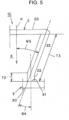
- a leg portion 23 of a modified example is described below with reference to FIG. 5 .
- a length T3 of this leg portion 23, in the example, is about 30 mm or more, which is longer compared to the length T1 of the leg portion 21.
- An inclination angle ⁇ 3 of the leg portion 23 is about 15° or more in this example. Further, an angle ⁇ 4 formed by the leg portion 23 and the welding portion 22 is, in this example, about 10° to the above angle ⁇ 3.
- the length T3 of the leg portion 23 of this modified example is longer than the length T1 of the leg portion 21 described above. Therefore, the allowance of overlapping, in the front view direction, between the leg portion 23 of this modified example and the leg portion 21L of the lamp lens 2L of the adjacent rear combination lamps 1L and 1R is longer (larger). This improves the sense of unity (connectedness) between the center-side rear combination lamp 1C and the right and left-side rear combination lamps 1L and 1R.
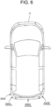
- FIGS. 6 to 8 show a second embodiment of the vehicle resin component according to the present invention.
- the configuration, operation, and effect of a vehicle resin component 100L of this second embodiment will be described below.
- the symbols same as those in FIGS. 1 through 5 indicate the same articles.
- the vehicle resin component 1C according to the above first embodiment is the center-side rear combination lamp 1C.
- the vehicle resin component 100L according to this second embodiment is the left-side rear combination lamp 100L (right-side rear combination lamp 100R).
- the center of the rear portion of the vehicle V is provided with a center-side rear combination lamp 100C.
- a center-side rear combination lamp 100C On the left and right sides in the rear portion of the vehicle V, and on the left and right sides of the center-side rear combination lamp 100C, a left-side rear combination lamp 100L and a right-side rear combination lamp 100R are respectively provided.
- the left-side rear combination lamp 100L is described below.
- the configuration of the right-side rear combination lamp 100R is symmetrical with the configuration of the left-side rear combination lamp 100L on right and left. For this reason, a description of the configuration of the right-side rear combination lamp 100R is omitted.
- the left-side rear combination lamp 100L has a lamp lens 200, a lamp housing 300, and a lamp housing.
- the lamp lens 200 and the lamp housing 300 are fixed to each other by a welding under pressure (i.e., hot plate welding).
- the lamp lens 200 and the lamp housing 300 form the lamp chamber 4.
- Lamp units optical members (inner lenses, etc.), decorative members (inner housings, inner panels, etc.), and mounting members (brackets, etc.), which are not shown in the drawing, are placed inside the lamp chamber 4.
- the lamp unit has a light source (not shown).
- the lamp units include, for example, tail lamps, stop lamps, turn signal lamps, and back lamps.
- the lamp lens 200 is made of light-transmitting resin (e.g., acrylic).
- the lamp lens 200 has a body portion 201, a leg portion 210, a welding portion 222, and a wrap-around portion 202.
- the leg portion 210's part that faces the center-side rear combination lamp 100C is provided from the edge portion of the body portion 201 to the lamp housing 3 side, sloping to the body portion 201 side.
- the lamp housing 300 is made of light-non-transmitting resin (such as ABS resin).
- the lamp housing 300 has a body portion 301, a welding portion 310, and a wrap-around portion 302.
- the body portion 201 and the body portion 301 are placed inside the vehicle V. Meanwhile, the wrap-around portion 202 and the wrap-around portion 302 are placed outside of the vehicle V, and on both the right and left sides of the vehicle V. In other words, the body portion 201 and the body portion 301 have the wrap-around portion 202 and the wrap-around portion 302 that wrap around to the leg portion 210 side of the lamp lens 200.
- the part, of the leg portion 210 of the lamp lens 200, that faces the center-side rear combination lamp 100C is provided from the edge portion of the body portion 201 to the lamp housing 300 side, sloping to the body portion 201.
- the welding portion 220 of the lamp lens 200 is bent from the tip of the leg portion 210 in the opposite direction of the direction of bending the leg portion 210 and is integrally provided.
- the welding portion 220 of the lamp lens 200 and the welding portion 310 of the lamp housing 300 are fixed to each other by the welding under pressure. This forms the lamp chamber 4.
- the vehicle resin component 100L according to the second embodiment has the above configuration, the same operation and effect as those of the vehicle resin component 1C according to the first embodiment described above can be achieved.
- the vehicle resin component 100L of this second embodiment even when the wrap-around portions 202 and 302 and the lengths of the wrap-around portions 202 and 302 are longer in the front/rear direction of the vehicle V, can secure the required weld strength.
- the pressing direction P slopes from the vertical direction to the right/left direction in FIG. 7 . This increases the leg portion 210's inclination angle relative to the pressing direction P.
- the vehicle resin component 100L according to this second embodiment has the welding portion 220 at the tip of the leg portion 210, the required weld strength can be secured even when the leg portion 210's inclination angle relative to the pressing direction P is increased.
- the above first and second embodiments describe the examples which use, as the vehicle resin components 1C, 100L, for the center-side rear combination lamp 1C, and the left-side rear combination lamp 100L (the right-side rear combination lamp 100R).
- the present invention can also use, as the vehicle resin component, for a vehicle lamp other than the rear combination lamp, or for any vehicle component other than the vehicle lamp, such as an optical member (inner lens, etc.) and a decorative member (inner housing, inner panel, etc.).
- the welding portions 22 and 220 each have a straight line shape.
- the welding portions 22, 220 may have a shape other than the straight shape, such as a curved shape.
- the length T2 of the welding portions 22 and 220 before the welding is about 1.0 mm or more.
- the length T2 of the welding portions 22 and 220 before the welding may be about 0.5 mm or more.
- the welding allowance of the welding portions 22 and 220 is about 0.5 mm, it is sufficient that the welding portions 22 and 220 is still present after the welding thereby to ensure the rigidity and the pressing force in the pressing direction P.
- the present invention is not limited to the first embodiment described above.
Landscapes
- Engineering & Computer Science (AREA)
- Mechanical Engineering (AREA)
- General Engineering & Computer Science (AREA)
- Non-Portable Lighting Devices Or Systems Thereof (AREA)
Abstract
Description
- The present invention relates to a resin component for vehicle.
- For example, there is a vehicle resin component in which a first resin member and a second resin member are fixed by welding under pressure, as shown in
Patent Literature 1. The following is a description of thePatent Literature 1. - A vehicle lamp of the
Patent Literature 1 is the one in which a convex portion of a translucent cover as the first resin member and a rib of a lamp body as the second resin member are fixed by vibration welding under pressure. - The vehicle lamp of the
Patent Literature 1 can ensure a required bond strength at a low cost and without loss of design, even when the translucent cover is so formed as to extend along a curved surface shape. - PTL1:
Japanese Unexamined Patent Application Publication No. 2011-146279 - Thus, it is important to ensure the required weld strength (bond strength) of the vehicle resin component (vehicle lamp) even when the shape of the first resin member (translucent cover) is formed in the desired design shape.
- The problem to be solved by the present invention is to provide a vehicle resin component that can secure a required weld strength even when the shape of a first resin member is formed in a desired design shape.
- A vehicle resin component of the present invention includes: a first resin member; and a second resin member, wherein the first resin member and the second resin member are fixed by welding under pressure, the first resin member has a body portion, a leg portion provided on the body portion inclined toward the body portion side relative to a direction of the welding under pressure, and a welding portion that is provided on the leg portion in a manner to be bent toward an opposite side of the body portion relative to an inclination direction of the leg portion and that is welded to the first resin member under pressure.
- In the vehicle resin component of the present invention, the first resin member is a lamp lens, the second resin member is a lamp housing, and the leg portion of the lamp lens is inclined relative to a front view direction in a manner to overlap, in the front view direction, with the lamp lens of a vehicle lamp adjacently mounted on a vehicle.
- In the vehicle resin component of the present invention, the first resin member is a lamp lens, the second resin member is a lamp housing, and the body portion of the lamp lens and the lamp housing have wrap-around portions that wrap around to the leg portion side of the lamp lens.
- A vehicle resin component of the present invention can ensure a required weld strength even when the shape of a first resin member is formed in the desired design shape.
-
- [
FIG. 1] FIG. 1 is a rear view of a vehicle in use (viewing the front side from the rear side of the vehicle), showing a first embodiment of a vehicle resin component according to the present invention. - [
FIG. 2] FIG. 2 is a cross-sectional view (cross-sectional view of the line II-II inFIG. 1 ). - [
FIG. 3] FIG. 3 is a partially enlarged cross-sectional view of an essential part.FIG. 3(A) is an enlarged cross-sectional view of a part III inFIG. 2 . -
FIG. 3(B) is a partially enlarged cross-sectional view of the case where the present invention is not performed. - [
FIG. 4] FIG. 4 is a partially enlarged cross-sectional view showing the essential part (partially enlarged cross-sectional view corresponding toFIG. 3(A) ). - [
FIG. 5] FIG. 5 is a partially enlarged cross-sectional view showing a modification of the essential part (partially enlarged cross-sectional view corresponding toFIG. 4 ). - [
FIG. 6] FIG. 6 is a flat rear view of the vehicle in use (viewing the down side from the upper side of the vehicle), showing a second embodiment of the vehicle resin component according to the present invention. - [
FIG. 7] FIG. 7 is a cross-sectional view (cross-sectional view corresponding toFIG. 2 ). - [
FIG. 8] FIG. 8 is a partially enlarged cross-sectional view of an essential part (enlarged cross-sectional view of part VIII inFIG. 7 ). - Two examples of embodiments (examples) of a vehicle resin component according to the present invention will be described in detail below based on the drawings.
- In this specification, front, rear, top, bottom, left, and right are front, rear, top, bottom, left, and right seen when the vehicle resin component (vehicle lamp) of the present invention is provided on a vehicle V.
- Since the drawings are schematic diagrams showing the vehicle resin component of the present invention, detailed parts of the vehicle resin component of the present invention are omitted in the drawings. In the cross-sectional view, any hatching is omitted.
-
FIGS. 1 to 5 show a first embodiment of a vehicle resin component according to the present invention. The following is a description of a configuration of the vehicle resin component according to this first embodiment. In the drawing, areference sign 1C represents the vehicle resin component according to this first embodiment (hereinafter simply referred to as "vehicle resin component"). - The
vehicle resin component 1C is a vehicle lamp, in this example a center-side rear combination lamp, as shown inFIG. 1 . Thevehicle resin component 1C is hereafter referred to as a center-siderear combination lamp 1C. - The center-side
rear combination lamp 1C is provided in the center portion in the rear portion of the vehicle V, in this example, on a movable-side back door. Thevehicle resin component 1C is provided over most of the entire width direction (right/left direction) of the vehicle V. - Left and right side portions in the rear portion of the vehicle V, in this example, the fixed-side vehicle body, are provided with a left-side
rear combination lamp 1L as a vehicle lamp, and also a right-siderear combination lamp 1R as a vehicle lamp, respectively. - The center-side
rear combination lamp 1C, the left-siderear combination lamp 1L, and the right-siderear combination lamp 1R constitute a vehicle lamp with a sense of unity (connectedness) over the entire width direction (right/left direction) of the vehicle V, i.e., a rear combination lamp. - The center-side
rear combination lamp 1C, as shown inFIGS. 1 ,2 ,3A , and4 , has alamp lens 2 as a first resin member and alamp housing 3 as a second resin member. - The
lamp lens 2 and thelamp housing 3 are fixed to each other by welding under pressure (i.e., hot plate welding). Thelamp lens 2 and the lamp housing 3 form alamp chamber 4. - Lamp units, optical members (inner lenses, etc.), decorative members (inner housings, inner panels, etc.), and mounting members (brackets, etc.), which are not shown in the drawing, are placed inside the
lamp chamber 4. - The lamp unit has a light source (not shown). The lamp units include, for example, tail lamps, stop lamps, turn signal lamps, and back lamps.
- The
lamp lens 2, in this example, is made of light-transmitting resin (e.g., acrylic). Thelamp lens 2 has abody portion 20, aleg portion 21, and awelding portion 22. - The
body portion 20 is plate-shaped having a plate thickness (wall thickness) of, in this example, about 1.0 mm to about 3.0 mm. Thebody portion 20 has a front view shape (viewing the front side from the rear side of the vehicle V) that is a long rectangular in shape in the transverse (right/left) direction. The thickness (wall thickness) of thebody portion 20, relative to a diameter of an ejector pin, requires, in this example, a minimum of about 1.0 mm. - The
leg portion 21 is inclined (bent) from the entire peripheral edge portion of thebody portion 20 to thelamp housing 3 side (from the rear side to the front side of the vehicle V) and is integrally provided. In other words, theleg portion 21 is provided on thebody portion 20 in a manner to be inclined to thebody portion 20 side at an angle θ1 relative to a direction P of the welding under pressure. The angle θ1 is from about 45° to about 60° in this example. - As shown in
FIG. 3(A) , theleg portion 21 is inclined relative to the front view direction in a manner to overlap, in the front view direction (the front-rear direction of the vehicle V), with alamp lens 2L of the left-siderear combination lamp 1L adjacently mounted on the vehicle V. This front view direction is substantially the same as, i.e., substantially parallel to the direction P of the welding under pressure described above. - The
welding portion 22 is bent from theleg portion 21's tip (opposite end to the end on thebody portion 20 side) in the opposite direction of the direction of bending theleg portion 21 and is integrally provided. In other words, thewelding portion 22 is provided at theleg portion 21 in a manner to be inclined at an angle θ2 relative to the inclination direction of theleg portion 21, opposite to thebody portion 20. The angle θ2 is, in this example, from about 20° to the above angle θ1. - A length T1 between the
leg portion 21 and thewelding portion 22 is, in this example, about 10 mm or more. The length T1 between theleg portion 21 and thewelding portion 22 is a length of theleg portion 21 in the inclination direction from thebody portion 20 to thelamp housing 3. - A length T2 of the
welding portion 22 is, in this example, about 1.0 mm or more. The length T2 of thewelding portion 22 is a length of thewelding portion 22 in the centerline direction from an edge portion bent with theleg portion 21 to thelamp housing 3. - The
lamp housing 3, in this example, is made of light-non-transmitting resin (such as ABS resin). Thelamp housing 3 has abody portion 30, awelding portion 31, and aconvex portion 32. - The
body portion 30, like thebody portion 20 of thelamp lens 2, is plate-shaped, and has a front view shape that is a long rectangular shape in the transverse direction. - On the front face of the body portion 30 (a face facing the lamp lens 2), the
welding portion 31 is integrally provided in a portion slightly closer to the center side from the entire peripheral edge portion of thebody portion 30. The front face of thewelding portion 31 is flush with the front face of thebody portion 30. - The
convex portion 32 is so provided as to integrally protrude from the entire peripheral edge portion of thebody portion 30 toward thelamp lens 2 side (from the front of the vehicle V to the rear). - First, the
lamp lens 2 and thelamp housing 3 are each stored and held in a jig by a suction pad or the like (not shown). - Next, the
welding portion 22 of thelamp lens 2 and thewelding portion 31 of thelamp housing 3 are softened by a heating plate (heating block) not shown in the drawing. Thewelding portion 22 of thelamp lens 2 and thewelding portion 31 of thelamp housing 3 may be in contact or non-contact with the heating block. - Then, through a jig, the
welding portion 22 of thelamp lens 2 is pressed onto thewelding portion 31 of thelamp housing 3 in the solid arrow direction P inFIG. 2 . This pressing direction P is perpendicular to thebody portion 20 of thelamp lens 2 and thebody portion 30 of thelamp housing 3. - Then, the
welding portion 22 of thelamp lens 2 and thewelding portion 31 of thelamp housing 3 are welded to each other. With this, thelamp lens 2 and thelamp housing 3 are integrally fixed and also form alamp chamber 4. - The welding allowance of the
welding portion 22 is about 0.5 mm at the maximum in this example. This means that the length T2 of thewelding portion 22 before the welding is, in this example, about 1.0 mm or more, so the length of thewelding portion 22 after the welding is, in this example, about 0.5 mm. As a result, thewelding portion 22 is always present during the welding step, making it possible to ensure the rigidity and the pressing force in the pressing direction P. - As described above, the center-side
rear combination lamp 1C as thevehicle resin component 1C according to this first embodiment is formed. - The left-side
rear combination lamp 1L is described below. Like the center-siderear combination lamp 1C described above, thelamp lens 2L of the left-siderear combination lamp 1L is provided with thelamp lens 2L and alamp housing 3L. - The
lamp lens 2L and thelamp housing 3L are fixed to each other by the welding under pressure (i.e., hot plate welding). Thelamp lens 2L and thelamp housing 3L form alamp chamber 4L. - Lamp units, optical members (inner lenses, etc.), decorative members (inner housings, inner panels, etc.), and mounting members (brackets, etc.), which are not shown in the drawing, are placed in the
lamp chamber 4L. The lamp unit has a light source (not shown). The lamp units include, for example, tail lamps, stop lamps, turn signal lamps, and back lamps. - The
lamp lens 2L, in this example, is made of light-transmitting resin (e.g., acrylic, etc.). Thelamp lens 2L has abody portion 20L, aleg portion 21L, and, awelding portion 22L. - The
leg portion 21L's part that faces the center-siderear combination lamp 1C described above is provided from the edge portion of thebody portion 20L to thelamp housing 3 side, sloping relative to thebody portion 20L to the opposite side. - This will mount this left-side
rear combination lamp 1L and the above center-siderear combination lamp 1C adjacent to each other on the vehicle V. Then, theleg portion 21L of thelamp lens 2L of the left-siderear combination lamp 1L and theleg portion 21 of thelamp lens 2 of the center-siderear combination lamp 1 overlap in the front view direction, as shown inFIG. 3(A) . - The configuration of the right-side
rear combination lamp 1R is symmetrical with the configuration of the left-siderear combination lamp 1L on right and left. For this reason, a description of the configuration of the right-siderear combination lamp 1R is omitted. - The center-side
rear combination lamp 1C according to this first embodiment has the above configuration, and its operation is described below. - Light sources of the lamp units of the
rear combination lamps body portions lamp lenses - In addition, a part of the light from the light source is transmitted through the
leg portions lamp lenses rear combination lamp 1C, the left-side (vehicle body on fixed-side)rear combination lamp 1L, and the right-side (vehicle body on fixed-side)rear combination lamp 1R appear to shine in unison across the entire width direction (right/left direction) of the vehicle V. In other words, therear combination lamps - The center-side
rear combination lamp 1C according to this first embodiment has the above configuration and operation, and its effect is described below. - The center-side
rear combination lamp 1C according to this first embodiment is the one that is, in thelamp lens 2 as the first resin member, theleg portion 21 is provided with thewelding portion 22 bent in the opposite direction relative to the inclination direction of theleg portion 21. With this, in the center-siderear combination lamp 1C according to this first embodiment, even when theleg portion 21 is inclined at the angle θ1 relative to the pressing direction P at the time of welding thelamp lens 2 to thelamp housing 3 under pressure, thewelding portion 22 is substantially in the same direction as the pressing direction P, making it possible for thewelding portion 22 to secure the rigidity and pressing force in the pressing direction P. - As a result, in the center-side
rear combination lamp 1C according to this first embodiment, thelamp lens 2 can be fixed to thelamp housing 3 by the welding under pressure via thewelding portion 22 even when theleg portion 21 of thelamp lens 2 is inclined relative to thebody portion 20. Thus, the center-siderear combination lamp 1C according to this first embodiment can ensure the required weld strength even when the shape of thebody portion 20 of thelamp lens 2 is formed in the desired design shape. - The center-side rear combination lamp (vehicle resin component, vehicle lamp) 1 without having been subjected to the present invention is described below with reference to
FIG. 3(B) . InFIG. 3(B) , the symbols same as those inFIGS. 1 ,2 ,3A and4 indicate the same articles. - This center-side
rear combination lamp 1 is the one in which theleg portion 21 is directly welded under pressure to thewelding portion 31 of thelamp housing 3 not via thewelding portion 22. As a result, in this center-siderear combination lamp 1, at the time of welding thelamp lens 2 to thelamp housing 3 under pressure, the pressing force in the direction P is broken in the inclination direction of theleg portion 21, and theleg portion 21 is unable to ensure the rigidity and the pressing force in the pressing direction P. The greater the inclination angle θ1 of theleg portion 21, the more difficult it is to ensure the rigidity and the pressing force. - As the case may be, this makes it impossible for this center-side
rear combination lamp 1 to ensure the required weld strength when the shape of thebody portion 20 of thelamp lens 2 is formed in the desired design shape. - In the center-side
rear combination lamp 1, making the plate thickness (wall thickness) of thelamp lens 2 about 3.0 mm or more, as the case may be, can secure the required weld strength. In this case, the increased thickness (wall thickness) of thelamp lens 2 increases weight and cost, and also causes sink and the like. - In contrast, the center-side
rear combination lamp 1C according to this first embodiment has theleg portion 21 that is welded under pressure to thewelding portion 31 of thelamp housing 3 via thewelding portion 22. With this, the center-siderear combination lamp 1 of this first embodiment can ensure the required weld strength even when the shape of thebody portion 20 of thelamp lens 2 is formed in the desired design shape. - Moreover, the center-side
rear combination lamp 1C according to this first embodiment does not require the plate thickness (wall thickness) of thelamp lens 2 to be thicker than about 3.0 mm or more; in this example, the thickness of thelamp lens 2 can be as thin as about 1.0 mm to about 3.0 mm. As a result, the center-siderear combination lamp 1C according to this first embodiment can reduce the weight and cost of the center-siderear combination lamp 1C by reducing the thickness (wall thickness) of thelamp lens 2, and can prevent sink and the like. - Further, the center-side
rear combination lamp 1C according to this first embodiment is the one where theleg portion 21 of thelamp lens 2 is inclined relative to the front view direction in a manner to overlap, in the front view direction, with theleg portion 21L of thelamp lens 2L of the left-siderear combination lamp 1L and right-siderear combination lamp 1R adjacently mounted on the vehicle V. As a result, with the center-siderear combination lamp 1C according to this first embodiment, a part of the light from the light source is transmitted through theleg portions lamp lenses - With this, the center-side
rear combination lamp 1C according to this first embodiment, together with the left-siderear combination lamp 1L and the right-siderear combination lamp 1R, appear to shine in unison across the entire width direction (right/left direction) of the vehicle V. In other words, therear combination lamps - A
leg portion 23 of a modified example is described below with reference toFIG. 5 . A length T3 of thisleg portion 23, in the example, is about 30 mm or more, which is longer compared to the length T1 of theleg portion 21. - An inclination angle θ3 of the
leg portion 23 is about 15° or more in this example. Further, an angle θ4 formed by theleg portion 23 and thewelding portion 22 is, in this example, about 10° to the above angle θ3. - Even in the case of the
leg portion 23 of this modified example, the same effect can be achieved as in theleg portion 21 described above. In particular, the length T3 of theleg portion 23 of this modified example is longer than the length T1 of theleg portion 21 described above. Therefore, the allowance of overlapping, in the front view direction, between theleg portion 23 of this modified example and theleg portion 21L of thelamp lens 2L of the adjacentrear combination lamps rear combination lamp 1C and the right and left-siderear combination lamps -
FIGS. 6 to 8 show a second embodiment of the vehicle resin component according to the present invention. The configuration, operation, and effect of avehicle resin component 100L of this second embodiment will be described below. In the drawings, the symbols same as those inFIGS. 1 through 5 indicate the same articles. - The
vehicle resin component 1C according to the above first embodiment is the center-siderear combination lamp 1C. Thevehicle resin component 100L according to this second embodiment is the left-siderear combination lamp 100L (right-siderear combination lamp 100R). - The center of the rear portion of the vehicle V is provided with a center-side
rear combination lamp 100C. On the left and right sides in the rear portion of the vehicle V, and on the left and right sides of the center-siderear combination lamp 100C, a left-siderear combination lamp 100L and a right-siderear combination lamp 100R are respectively provided. - The left-side
rear combination lamp 100L is described below. The configuration of the right-siderear combination lamp 100R is symmetrical with the configuration of the left-siderear combination lamp 100L on right and left. For this reason, a description of the configuration of the right-siderear combination lamp 100R is omitted. - The left-side
rear combination lamp 100L has alamp lens 200, alamp housing 300, and a lamp housing. Thelamp lens 200 and thelamp housing 300 are fixed to each other by a welding under pressure (i.e., hot plate welding). Thelamp lens 200 and thelamp housing 300 form thelamp chamber 4. - Lamp units, optical members (inner lenses, etc.), decorative members (inner housings, inner panels, etc.), and mounting members (brackets, etc.), which are not shown in the drawing, are placed inside the
lamp chamber 4. The lamp unit has a light source (not shown). The lamp units include, for example, tail lamps, stop lamps, turn signal lamps, and back lamps. - The
lamp lens 200 is made of light-transmitting resin (e.g., acrylic). Thelamp lens 200 has abody portion 201, aleg portion 210, a welding portion 222, and a wrap-aroundportion 202. - The
leg portion 210's part that faces the center-siderear combination lamp 100C is provided from the edge portion of thebody portion 201 to thelamp housing 3 side, sloping to thebody portion 201 side. - The
lamp housing 300 is made of light-non-transmitting resin (such as ABS resin). Thelamp housing 300 has abody portion 301, awelding portion 310, and a wrap-aroundportion 302. - The
body portion 201 and thebody portion 301 are placed inside the vehicle V. Meanwhile, the wrap-aroundportion 202 and the wrap-aroundportion 302 are placed outside of the vehicle V, and on both the right and left sides of the vehicle V. In other words, thebody portion 201 and thebody portion 301 have the wrap-aroundportion 202 and the wrap-aroundportion 302 that wrap around to theleg portion 210 side of thelamp lens 200. - The part, of the
leg portion 210 of thelamp lens 200, that faces the center-siderear combination lamp 100C is provided from the edge portion of thebody portion 201 to thelamp housing 300 side, sloping to thebody portion 201. - The
welding portion 220 of thelamp lens 200 is bent from the tip of theleg portion 210 in the opposite direction of the direction of bending theleg portion 210 and is integrally provided. - The
welding portion 220 of thelamp lens 200 and thewelding portion 310 of thelamp housing 300 are fixed to each other by the welding under pressure. This forms thelamp chamber 4. - Since the
vehicle resin component 100L according to the second embodiment has the above configuration, the same operation and effect as those of thevehicle resin component 1C according to the first embodiment described above can be achieved. - In particular, the
vehicle resin component 100L of this second embodiment, even when the wrap-aroundportions portions - In other words, as the lengths of the wrap-around
portions FIG. 7 . This increases theleg portion 210's inclination angle relative to the pressing direction P. - However, since the
vehicle resin component 100L according to this second embodiment has thewelding portion 220 at the tip of theleg portion 210, the required weld strength can be secured even when theleg portion 210's inclination angle relative to the pressing direction P is increased. - The above first and second embodiments describe the examples which use, as the
vehicle resin components rear combination lamp 1C, and the left-siderear combination lamp 100L (the right-siderear combination lamp 100R). However, the present invention can also use, as the vehicle resin component, for a vehicle lamp other than the rear combination lamp, or for any vehicle component other than the vehicle lamp, such as an optical member (inner lens, etc.) and a decorative member (inner housing, inner panel, etc.). - In the above first and second embodiments, the
welding portions welding portions welding portions - Further, in the above first and second embodiments, the length T2 of the
welding portions welding portions welding portions welding portions - Incidentally, the present invention is not limited to the first embodiment described above.
-
- 1C: center-side
rear combination lamp 1C (vehicle resin component, vehicle lamp) - 1L: left-side rear combination lamp (vehicle lamp)
- 1R: right-side rear combination lamp (vehicle lamp)
- 2: lamp lens (first resin member)
- 20: body portion
- 21: leg portion
- 22: welding portion
- 23: leg portion
- 3: lamp housing (second resin member)
- 30: body portion
- 31: welding portion
- 32: convex portion
- 4: lamp chamber
- 2L: lamp lens
- 20L: body portion
- 21L: leg portion
- 22L: welding portion
- 3L: lamp housing
- 30L: body portion
- 31L: welding portion
- 4L: lamp chamber
- 100C: center-side
rear combination lamp 1C (vehicle lamp) - 100L: left-side rear combination lamp (vehicle resin component, vehicle lamp)
- 100R: right-side rear combination lamp (vehicle resin component, vehicle lamp)
- 200: lamp lens (first resin member)
- 201: body portion
- 202: wrap-around portion
- 210 leg portion
- 220 welding portion
- 300 lamp housing (second resin member)
- 301: body portion
- 302 wrap-around portion
- 310: welding portion
- P: pressing direction
- T1: dimension length
- T2 dimension length
- T3 dimension length
- V: vehicle
- θ1: angle
- θ2: angle
- θ3: angle
- θ4: angle
Claims (3)
- A vehicle resin component (1C, 100L), comprising:a first resin member (2, 200); anda second resin member (3, 300),wherein
the first resin member (2, 200) and the second resin member (3, 300) are fixed by welding under pressure,the first resin member (2, 200) hasa body portion (20, 201),a leg portion (21, 210) provided on the body portion (20, 201) inclined toward the body portion (20, 201) side relative to a direction of the welding under pressure, anda welding portion (22, 220) that is provided on the leg portion (21, 210) in a manner to be bent toward an opposite side of the body portion (20, 201) relative to an inclination direction of the leg portion (21, 210) and that is welded to the first resin member (2, 200) under pressure. - The vehicle resin component (1C) according to claim 1, whereinthe first resin member (2) is a lamp lens (2),the second resin member (3) is a lamp housing (3), andthe leg portion (21) of the lamp lens (2) is inclined relative to a front view direction in a manner to overlap, in the front view direction, with the lamp lens (2) of a vehicle lamp (1L, 1R) adjacently mounted on a vehicle (V).
- The vehicle resin component (100L) according to claim 1, whereinthe first resin member (200) is a lamp lens (200),the second resin member (300) is a lamp housing (300), andthe body portion (201) of the lamp lens (200) and the lamp housing (300) have wrap-around portions (202, 302) that wrap around to the leg portion (210) side of the lamp lens (200).
Applications Claiming Priority (2)
| Application Number | Priority Date | Filing Date | Title |
|---|---|---|---|
| JP2020080281A JP7359076B2 (en) | 2020-04-30 | 2020-04-30 | Vehicle resin parts |
| PCT/JP2021/017168 WO2021221154A1 (en) | 2020-04-30 | 2021-04-30 | Resin component for vehicle |
Publications (2)
| Publication Number | Publication Date |
|---|---|
| EP4145046A1 true EP4145046A1 (en) | 2023-03-08 |
| EP4145046A4 EP4145046A4 (en) | 2024-06-05 |
Family
ID=78279885
Family Applications (1)
| Application Number | Title | Priority Date | Filing Date |
|---|---|---|---|
| EP21797408.8A Pending EP4145046A4 (en) | 2020-04-30 | 2021-04-30 | RESIN ELEMENT FOR A VEHICLE |
Country Status (5)
| Country | Link |
|---|---|
| US (1) | US11940117B2 (en) |
| EP (1) | EP4145046A4 (en) |
| JP (1) | JP7359076B2 (en) |
| CN (1) | CN115485501B (en) |
| WO (1) | WO2021221154A1 (en) |
Families Citing this family (1)
| Publication number | Priority date | Publication date | Assignee | Title |
|---|---|---|---|---|
| WO2026062792A1 (en) * | 2024-09-18 | 2026-03-26 | 日産自動車株式会社 | Back door for vehicle and vehicle comprising back door for vehicle |
Family Cites Families (19)
| Publication number | Priority date | Publication date | Assignee | Title |
|---|---|---|---|---|
| US4733335A (en) * | 1984-12-28 | 1988-03-22 | Koito Manufacturing Co., Ltd. | Vehicular lamp |
| KR100293375B1 (en) * | 1996-03-05 | 2001-07-12 | 고지마 류조 | Vehicle lamp and vibrtion type welding method for the vehicle lamp |
| JPH10125112A (en) * | 1996-10-17 | 1998-05-15 | Koito Mfg Co Ltd | Vehicle lighting |
| JP3225006B2 (en) * | 1997-07-10 | 2001-11-05 | 株式会社小糸製作所 | Vehicle lighting |
| JP3337125B2 (en) * | 1998-01-23 | 2002-10-21 | スタンレー電気株式会社 | Vehicle light with reflex reflector |
| JP3913435B2 (en) * | 2000-02-29 | 2007-05-09 | 株式会社小糸製作所 | Manufacturing method of vehicular lamp |
| JP2004319347A (en) * | 2003-04-18 | 2004-11-11 | Koito Mfg Co Ltd | Vehicle lighting lens |
| DE102004050744A1 (en) * | 2004-10-19 | 2006-05-24 | Hella Kgaa Hueck & Co. | Headlights for vehicles and manufacturing processes |
| JP4716512B2 (en) * | 2006-06-26 | 2011-07-06 | 株式会社小糸製作所 | VEHICLE LIGHT AND METHOD FOR PRODUCING VEHICLE LIGHT |
| JP2011146279A (en) | 2010-01-15 | 2011-07-28 | Koito Mfg Co Ltd | Vehicular lighting fixture |
| JP2012028143A (en) * | 2010-07-22 | 2012-02-09 | Stanley Electric Co Ltd | Lamp fitting for vehicle and manufacturing method of lamp fitting for vehicle |
| JP5516371B2 (en) * | 2010-11-30 | 2014-06-11 | マツダ株式会社 | Rear structure of the vehicle |
| JP5731184B2 (en) * | 2010-12-15 | 2015-06-10 | 株式会社小糸製作所 | Vehicle lamp |
| JP5941714B2 (en) * | 2012-03-16 | 2016-06-29 | スタンレー電気株式会社 | Manufacturing method of vehicular lamp |
| JP5652482B2 (en) * | 2013-01-17 | 2015-01-14 | トヨタ自動車株式会社 | Vehicle lamp structure |
| JP2016095996A (en) * | 2014-11-14 | 2016-05-26 | スタンレー電気株式会社 | Composite lamp for vehicles |
| ITUB20150956A1 (en) * | 2015-06-01 | 2016-12-01 | Automotive Lighting Italia S P A A Socio Unico | Method of manufacturing an automotive light and related automotive light |
| US20190176686A1 (en) * | 2017-12-11 | 2019-06-13 | American Craft And Design Llc | Motor vehicle light cover |
| JP7283915B2 (en) * | 2019-02-18 | 2023-05-30 | 株式会社小糸製作所 | vehicle lighting |
-
2020
- 2020-04-30 JP JP2020080281A patent/JP7359076B2/en active Active
-
2021
- 2021-04-30 US US17/997,446 patent/US11940117B2/en active Active
- 2021-04-30 EP EP21797408.8A patent/EP4145046A4/en active Pending
- 2021-04-30 WO PCT/JP2021/017168 patent/WO2021221154A1/en not_active Ceased
- 2021-04-30 CN CN202180031589.XA patent/CN115485501B/en active Active
Also Published As
| Publication number | Publication date |
|---|---|
| JP2021174745A (en) | 2021-11-01 |
| CN115485501A (en) | 2022-12-16 |
| US11940117B2 (en) | 2024-03-26 |
| EP4145046A4 (en) | 2024-06-05 |
| US20230265986A1 (en) | 2023-08-24 |
| WO2021221154A1 (en) | 2021-11-04 |
| CN115485501B (en) | 2025-12-19 |
| JP7359076B2 (en) | 2023-10-11 |
Similar Documents
| Publication | Publication Date | Title |
|---|---|---|
| KR101125961B1 (en) | Vehicular lamp | |
| US12422121B2 (en) | Optical element and light module of a motor vehicle equipped with such an optical element | |
| CN104822983B (en) | Light guide for lighting and/or signaling devices of motor vehicles | |
| US20220268415A1 (en) | Vehicle grille | |
| US9169987B2 (en) | Lighting appliance for vehicles | |
| US6997586B2 (en) | Structure for maintaining clearance between headlamp and fender of vehicle | |
| US11649939B2 (en) | Automotive lighting and/or signaling device and assembly method thereof | |
| CN111132873A (en) | Vehicle interior parts | |
| US8070335B2 (en) | Fixture for a headlight unit, method for the production thereof, and front unit | |
| EP4145046A1 (en) | Resin component for vehicle | |
| JP2009140779A (en) | Vehicle signal lights | |
| JP5297093B2 (en) | Vehicle lamp | |
| US10344939B2 (en) | Vehicle lighting assembly | |
| US9366406B2 (en) | Space saving lighting device for vehicles | |
| US20250003569A1 (en) | Through lamp for vehicle and vehicle having same | |
| JP7169549B2 (en) | Vehicle lighting device | |
| JP6053600B2 (en) | Light emitting device for vehicle | |
| US20220340077A1 (en) | Lamp for vehicle and vehicle including the same | |
| US11739904B2 (en) | Lighting apparatus for a vehicle having a planar light guide and an elongate light guide | |
| CN102126462B (en) | Rear lamp structure | |
| JP7217930B2 (en) | vehicle lamp | |
| JP2018120669A (en) | Lamp | |
| KR101510207B1 (en) | Support panel assembly for rear lamp of vehicle and method of manufacturing the same | |
| JP7806731B2 (en) | Vehicle outer mirror | |
| EP4528150A1 (en) | Automotive lighting device and relative production method |
Legal Events
| Date | Code | Title | Description |
|---|---|---|---|
| STAA | Information on the status of an ep patent application or granted ep patent |
Free format text: STATUS: THE INTERNATIONAL PUBLICATION HAS BEEN MADE |
|
| PUAI | Public reference made under article 153(3) epc to a published international application that has entered the european phase |
Free format text: ORIGINAL CODE: 0009012 |
|
| STAA | Information on the status of an ep patent application or granted ep patent |
Free format text: STATUS: REQUEST FOR EXAMINATION WAS MADE |
|
| 17P | Request for examination filed |
Effective date: 20221024 |
|
| AK | Designated contracting states |
Kind code of ref document: A1 Designated state(s): AL AT BE BG CH CY CZ DE DK EE ES FI FR GB GR HR HU IE IS IT LI LT LU LV MC MK MT NL NO PL PT RO RS SE SI SK SM TR |
|
| DAV | Request for validation of the european patent (deleted) | ||
| DAX | Request for extension of the european patent (deleted) | ||
| A4 | Supplementary search report drawn up and despatched |
Effective date: 20240508 |
|
| RIC1 | Information provided on ipc code assigned before grant |
Ipc: B29L 31/00 20060101ALN20240502BHEP Ipc: B29L 31/30 20060101ALN20240502BHEP Ipc: B29C 65/14 20060101ALN20240502BHEP Ipc: B29C 65/06 20060101ALN20240502BHEP Ipc: F21S 43/20 20180101ALI20240502BHEP Ipc: B60Q 1/30 20060101ALI20240502BHEP Ipc: B29C 65/20 20060101ALI20240502BHEP Ipc: F21W 103/45 20180101ALI20240502BHEP Ipc: F21W 103/35 20180101ALI20240502BHEP Ipc: F21W 103/20 20180101ALI20240502BHEP Ipc: F21W 103/00 20180101ALI20240502BHEP Ipc: F21S 43/27 20180101ALI20240502BHEP Ipc: F21W 105/00 20180101AFI20240502BHEP |
|
| STAA | Information on the status of an ep patent application or granted ep patent |
Free format text: STATUS: EXAMINATION IS IN PROGRESS |
|
| 17Q | First examination report despatched |
Effective date: 20250625 |
|
| RIC1 | Information provided on ipc code assigned before grant |
Ipc: F21W 105/00 20180101AFI20260203BHEP Ipc: F21S 43/27 20180101ALI20260203BHEP Ipc: F21W 103/00 20180101ALI20260203BHEP Ipc: F21W 103/20 20180101ALI20260203BHEP Ipc: F21W 103/35 20180101ALI20260203BHEP Ipc: F21W 103/45 20180101ALI20260203BHEP Ipc: B29C 65/20 20060101ALI20260203BHEP Ipc: B60Q 1/30 20060101ALI20260203BHEP Ipc: F21S 43/20 20180101ALI20260203BHEP Ipc: B29C 65/06 20060101ALN20260203BHEP Ipc: B29C 65/14 20060101ALN20260203BHEP Ipc: B29L 31/30 20060101ALN20260203BHEP Ipc: B29L 31/00 20060101ALN20260203BHEP |
|
| GRAP | Despatch of communication of intention to grant a patent |
Free format text: ORIGINAL CODE: EPIDOSNIGR1 |
|
| STAA | Information on the status of an ep patent application or granted ep patent |
Free format text: STATUS: GRANT OF PATENT IS INTENDED |
|
| INTG | Intention to grant announced |
Effective date: 20260312 |