EP4144986B1 - Windturbinengondel mit mindestens einer verschiebbaren dachplatte - Google Patents
Windturbinengondel mit mindestens einer verschiebbaren dachplatte Download PDFInfo
- Publication number
- EP4144986B1 EP4144986B1 EP21382800.7A EP21382800A EP4144986B1 EP 4144986 B1 EP4144986 B1 EP 4144986B1 EP 21382800 A EP21382800 A EP 21382800A EP 4144986 B1 EP4144986 B1 EP 4144986B1
- Authority
- EP
- European Patent Office
- Prior art keywords
- roof
- nacelle
- wind turbine
- displaceable
- roof panel
- Prior art date
- Legal status (The legal status is an assumption and is not a legal conclusion. Google has not performed a legal analysis and makes no representation as to the accuracy of the status listed.)
- Active
Links
Images


Classifications
-
- F—MECHANICAL ENGINEERING; LIGHTING; HEATING; WEAPONS; BLASTING
- F03—MACHINES OR ENGINES FOR LIQUIDS; WIND, SPRING, OR WEIGHT MOTORS; PRODUCING MECHANICAL POWER OR A REACTIVE PROPULSIVE THRUST, NOT OTHERWISE PROVIDED FOR
- F03D—WIND MOTORS
- F03D1/00—Wind motors with rotation axis substantially parallel to the air flow entering the rotor
- F03D1/101—Nacelles
- F03D1/125—Access thereto, e.g. doors or platforms
-
- F—MECHANICAL ENGINEERING; LIGHTING; HEATING; WEAPONS; BLASTING
- F03—MACHINES OR ENGINES FOR LIQUIDS; WIND, SPRING, OR WEIGHT MOTORS; PRODUCING MECHANICAL POWER OR A REACTIVE PROPULSIVE THRUST, NOT OTHERWISE PROVIDED FOR
- F03D—WIND MOTORS
- F03D80/00—Details, components or accessories not provided for in groups F03D1/00 - F03D17/00
- F03D80/80—Arrangement of components within nacelles or towers
-
- F—MECHANICAL ENGINEERING; LIGHTING; HEATING; WEAPONS; BLASTING
- F03—MACHINES OR ENGINES FOR LIQUIDS; WIND, SPRING, OR WEIGHT MOTORS; PRODUCING MECHANICAL POWER OR A REACTIVE PROPULSIVE THRUST, NOT OTHERWISE PROVIDED FOR
- F03D—WIND MOTORS
- F03D80/00—Details, components or accessories not provided for in groups F03D1/00 - F03D17/00
- F03D80/50—Maintenance or repair
-
- F—MECHANICAL ENGINEERING; LIGHTING; HEATING; WEAPONS; BLASTING
- F05—INDEXING SCHEMES RELATING TO ENGINES OR PUMPS IN VARIOUS SUBCLASSES OF CLASSES F01-F04
- F05B—INDEXING SCHEME RELATING TO WIND, SPRING, WEIGHT, INERTIA OR LIKE MOTORS, TO MACHINES OR ENGINES FOR LIQUIDS COVERED BY SUBCLASSES F03B, F03D AND F03G
- F05B2240/00—Components
- F05B2240/10—Stators
- F05B2240/14—Casings, housings, nacelles, gondels or the like, protecting or supporting assemblies there within
-
- Y—GENERAL TAGGING OF NEW TECHNOLOGICAL DEVELOPMENTS; GENERAL TAGGING OF CROSS-SECTIONAL TECHNOLOGIES SPANNING OVER SEVERAL SECTIONS OF THE IPC; TECHNICAL SUBJECTS COVERED BY FORMER USPC CROSS-REFERENCE ART COLLECTIONS [XRACs] AND DIGESTS
- Y02—TECHNOLOGIES OR APPLICATIONS FOR MITIGATION OR ADAPTATION AGAINST CLIMATE CHANGE
- Y02E—REDUCTION OF GREENHOUSE GAS [GHG] EMISSIONS, RELATED TO ENERGY GENERATION, TRANSMISSION OR DISTRIBUTION
- Y02E10/00—Energy generation through renewable energy sources
- Y02E10/70—Wind energy
- Y02E10/72—Wind turbines with rotation axis in wind direction
Definitions
- the present disclosure relates to wind turbines, and more particularly relates to wind turbine nacelles.
- the present disclosure further relates to methods to provide access to a nacelle from above.
- a wind turbine generally includes a tower with a nacelle supported on top of the tower.
- a wind turbine rotor comprising a hub and a plurality of wind turbine blades may be rotatably mounted to the nacelle.
- the wind turbine blades may be set in motion by wind.
- the hub of the wind turbine may be operatively coupled with a rotor of a generator. As the hub and blades rotate, the kinetic energy of the wind is converted to kinetic mechanical energy of the wind turbine rotor and ultimately to electrical energy or power in the generator.
- the generator may typically be arranged inside the nacelle.
- the wind turbine rotor may be coupled directly to the generator rotor in so-called direct drive wind turbines.
- the wind turbine rotor may include a main rotor shaft (a so-called "low speed shaft") which leads to a gearbox.
- a high-speed shaft of the gearbox may then drive the generator.
- the electrical power output of the generator may be fed to an electric grid.
- the connection of the generator to the grid may include e.g. a converter, transformer, medium voltage line and other.
- Elements like the gearbox, the generator, and converter, electrical power cables, cooling systems and structures may be partly or completely housed in a nacelle.
- the nacelle provides a cover to protect such elements from the outside environment.
- the nacelle may comprise a structural frame made of e.g. steel beams and bars and a housing or enclosure made of a composite material such as glass fibre reinforced composites.
- a wind turbine comprising a hatch on the roof of a nacelle is disclosed in EP 3372730 A1 . Further prior art is disclosed in US2011097202 A1 , US 2016237986 A1 , and US 2014030111 A1 .
- the present disclosure provides methods that avoid the use of such a large crane.
- a wind turbine nacelle according to claim 1 is provided.
- a wind turbine nacelle is provided to which access can be provided from above the nacelle without the need for a ground mounted crane.
- a nacelle mounted crane may be erected or unfolded thanks to space created by removing the roof panel.
- a method for providing access to an inside of a wind turbine nacelle comprises detaching a displaceable roof panel from other portions of a roof of the nacelle and lifting the displaceable roof panel from an inside of the nacelle.
- the method further comprises displacing the displaceable roof panel towards a front or a rear of the nacelle.
- FIG. 1 is a perspective view of an example of a wind turbine 10.
- the wind turbine 10 is a horizontal-axis wind turbine.
- the wind turbine 10 may be a vertical-axis wind turbine.
- the wind turbine 10 includes a tower 100 that extends from a support system 14 on a ground 12, a nacelle 16 mounted on tower 100, and a rotor 18 that is coupled to nacelle 16.
- the rotor 18 includes a rotatable hub 20 and at least one rotor blade 22 coupled to and extending outward from the hub 20.
- the rotor 18 has three rotor blades 22.
- the rotor 18 includes more or less than three rotor blades 22.
- the tower 100 may be fabricated from tubular steel to define a cavity (not shown in Figure 1 ) between a support system 14 and the nacelle 16.
- the tower 100 is any suitable type of a tower having any suitable height.
- the tower can be a hybrid tower comprising a portion made of concrete and a tubular steel portion.
- the tower can be a partial or full lattice tower.
- the rotor blades 22 are spaced about the hub 20 to facilitate rotating the rotor 18 to enable kinetic energy to be transferred from the wind into usable mechanical energy, and subsequently, electrical energy.
- the rotor blades 22 are mated to the hub 20 by coupling a blade root portion 24 to the hub 20 at a plurality of load transfer regions 26.
- the load transfer regions 26 may have a hub load transfer region and a blade load transfer region (both not shown in Figure 1 ). Loads induced to the rotor blades 22 are transferred to the hub 20 via the load transfer regions 26.
- the rotor blades 22 may have a length ranging from about 15 meters (m) to about 90 m or more.
- Rotor blades 22 may have any suitable length that enables the wind turbine 10 to function as described herein.
- blade lengths include 20 m or less, 37 m, 48.7 m, 50.2m, 52.2 m or a length that is greater than 91 m.
- the rotor 18 is rotated about a rotor axis 30.
- the rotor blades 22 are also subjected to various forces and moments. As such, the rotor blades 22 may deflect and/or rotate from a neutral, or non-deflected, position to a deflected position.
- a pitch angle of the rotor blades 22, i.e., an angle that determines an orientation of the rotor blades 22 with respect to the wind direction, may be changed by a pitch system 32 to control the load and power generated by the wind turbine 10 by adjusting an angular position of at least one rotor blade 22 relative to wind vectors. Pitch axes 34 of rotor blades 22 are shown.
- the pitch system 32 may particularly change a pitch angle of the rotor blades 22 such that the angle of attack of (portions of) the rotor blades are reduced, which facilitates reducing a rotational speed and/or facilitates a stall of the rotor 18.
- a blade pitch of each rotor blade 22 is controlled individually by a wind turbine controller 36 or by a pitch control system 80.
- the blade pitch for all rotor blades 22 may be controlled simultaneously by said control systems.
- a yaw direction of the nacelle 16 may be rotated about a yaw axis 38 to position the rotor blades 22 with respect to wind direction 28.
- the wind turbine controller 36 is shown as being centralized within the nacelle 16, however, the wind turbine controller 36 may be a distributed system throughout the wind turbine 10, on the support system 14, within a wind farm, and/or at a remote control center.
- the wind turbine controller 36 includes a processor 40 configured to perform the methods and/or steps described herein. Further, many of the other components described herein include a processor.
- processor is not limited to integrated circuits referred to in the art as a computer, but broadly refers to a controller, a microcontroller, a microcomputer, a programmable logic controller (PLC), an application specific, integrated circuit, and other programmable circuits, and these terms are used interchangeably herein. It should be understood that a processor and/or a control system can also include memory, input channels, and/or output channels.
- PLC programmable logic controller
- FIG. 2 is an enlarged sectional view of a portion of the wind turbine 10.
- the wind turbine 10 includes the nacelle 16 and the rotor 18 that is rotatably coupled to the nacelle 16. More specifically, the hub 20 of the rotor 18 is rotatably coupled to an electric generator 42 positioned within the nacelle 16 by the main shaft 44, a gearbox 46, a high-speed shaft 48, and a coupling 50.
- the main shaft 44 is disposed at least partially coaxial to a longitudinal axis (not shown) of the nacelle 16.
- a rotation of the main shaft 44 drives the gearbox 46 that subsequently drives the high-speed shaft 48 by translating the relatively slow rotational movement of the rotor 18 and of the main shaft 44 into a relatively fast rotational movement of the high-speed shaft 48.
- the latter is connected to the generator 42 for generating electrical energy with the help of a coupling 50.
- a transformer 90 and/or suitable electronics, switches, and/or inverters may be arranged in the nacelle 16 in order to transform electrical energy generated by the generator 42 having a voltage between 400V to 1000 V into electrical energy having medium voltage (10 - 35 KV) or higher voltage, e.g. 66kV. Said electrical energy is conducted via power cables 160 from the nacelle 16 into the tower 100.
- the gearbox 46, generator 42 in transformer 90 may be supported by a main support structure frame of the nacelle 16, optionally embodied as a main frame 52.
- the gearbox 46 may include a gearbox housing that is connected to the main frame 52 by one or more torque arms 103.
- the nacelle 16 also includes a main forward support bearing 60 and a main aft support bearing 62.
- the generator 42 can be mounted to the main frame 52 by decoupling support means 54, in particular in order to prevent vibrations of the generator 42 to be introduced into the main frame 52 and thereby causing a noise emission source.
- the main frame 52 is configured to carry the entire load caused by the weight of the rotor 18 and components of the nacelle 16 and by the wind and rotational loads, and furthermore, to introduce these loads into the tower 100 of the wind turbine 10.
- the rotor shaft 44, generator 42, gearbox 46, high speed shaft 48, coupling 50, and any associated fastening, support, and/or securing device including, but not limited to, support 52, and forward support bearing 60 and aft support bearing 62, are sometimes referred to as a drive train 64.
- the nacelle 16 also may include a yaw drive mechanism 56 that may be used to rotate the nacelle 16 and thereby also the rotor 18 about the yaw axis 38 to control the perspective of the rotor blades 22 with respect to the wind direction 28.
- a yaw drive mechanism 56 may be used to rotate the nacelle 16 and thereby also the rotor 18 about the yaw axis 38 to control the perspective of the rotor blades 22 with respect to the wind direction 28.
- the nacelle 16 may also include at least one meteorological measurement system which may include a wind vane and anemometer.
- the meteorological measurement system 58 can provide information to the wind turbine controller 36 that may include wind direction 28 and/or wind speed.
- the pitch system 32 is at least partially arranged as a pitch assembly 66 in the hub 20.
- the pitch assembly 66 includes one or more pitch drive systems 68 and at least one sensor 70.
- Each pitch drive system 68 is coupled to a respective rotor blade 22 (shown in Figure 1 ) for modulating the pitch angel of a rotor blade 22 along the pitch axis 34. Only one of three pitch drive systems 68 is shown in Figure 2 .
- the pitch assembly 66 includes at least one pitch bearing 72 coupled to hub 20 and to a respective rotor blade 22 (shown in FIG. 1 ) for rotating the respective rotor blade 22 about the pitch axis 34.
- the pitch drive system 68 includes a pitch drive motor 74, a pitch drive gearbox 76, and a pitch drive pinion 78.
- the pitch drive motor 74 is coupled to the pitch drive gearbox 76 such that the pitch drive motor 74 imparts mechanical force to the pitch drive gearbox 76.
- the pitch drive gearbox 76 is coupled to the pitch drive pinion 78 such that the pitch drive pinion 78 is rotated by the pitch drive gearbox 76.
- the pitch bearing 72 is coupled to pitch drive pinion 78 such that the rotation of the pitch drive pinion 78 causes a rotation of the pitch bearing 72.
- Pitch drive system 68 is coupled to the wind turbine controller 36 for adjusting the pitch angle of a rotor blade 22 upon receipt of one or more signals from the wind turbine controller 36.
- the pitch drive motor 74 is any suitable motor driven by electrical power and/or a hydraulic system that enables pitch assembly 66 to function as described herein.
- the pitch assembly 66 may include any suitable structure, configuration, arrangement, and/or components such as, but not limited to, hydraulic cylinders, springs, and/or servomechanisms.
- the pitch drive motor 74 is driven by energy extracted from a rotational inertia of hub 20 and/or a stored energy source (not shown) that supplies energy to components of the wind turbine 10.
- the pitch assembly 66 may also include one or more pitch control systems 80 for controlling the pitch drive system 68 according to control signals from the wind turbine controller 36, in case of specific prioritized situations and/or during rotor 18 overspeed.
- the pitch assembly 66 includes at least one pitch control system 80 communicatively coupled to a respective pitch drive system 68 for controlling pitch drive system 68 independently from the wind turbine controller 36.
- the pitch control system 80 is coupled to the pitch drive system 68 and to a sensor 70.
- the wind turbine controller 36 may control the pitch drive system 68 to adjust a pitch angle of rotor blades 22.
- a power supply 84 for example comprising a battery, electric capacitors hence letter or an electrical generator driven by the rotation of the hub 20, is arranged at or within the hub 20 and is coupled to the sensor 70, the pitch control system 80, and to the pitch drive system 68 to provide a source of power to these components.
- the power supply 84 provides a continuing source of power to the pitch assembly 66 during operation of the wind turbine 10.
- power supply 84 provides power to the pitch assembly 66 only during an electrical power loss event of the wind turbine 10.
- the electrical power loss event may include power grid loss or dip, malfunctioning of an electrical system of the wind turbine 10, and/or failure of the wind turbine controller 36.
- the power supply 84 operates to provide electrical power to the pitch assembly 66 such that pitch assembly 66 can operate during the electrical power loss event.
- the pitch drive system 68, the sensor 70, the pitch control system 80, cables, and the power supply 84 are each positioned in a cavity 86 defined by an inner surface 88 of hub 20.
- said components are positioned with respect to an outer surface of hub 20 and may be coupled, directly or indirectly, to outer surface.
- FIG 3 schematically illustrates an example of a wind turbine nacelle.
- the housing may be made up of a plurality of panels, which may be made of e.g. a fibre reinforced composite.
- a (steel) structural frame may be provided inside the housing. The frame may be attached to the housing such that the loads on the housing can be transmitted to the frame and to the wind turbine tower.
- a wind turbine nacelle 16 comprises a housing including a front side 270, and a rear side 250 separated from the front side along an axial direction x.
- the housing further comprises a first sidewall 260 and a second sidewall (not visible in this side view) extending from the front side 270 to the rear side 250.
- the housing also comprises a roof.
- the roof comprises one or more roof panels 210, 220, 230, 240, and at least one of the roof panels 210, 220, 230, 240 is a displaceable roof panel configured to be displaced along the axial direction x to provide access to the nacelle 16 from above.
- the displaceable roof panel can be displaced with respect to a part of the nacelle, i.e. not the whole nacelle roof is displaced.
- the front side 270 may be defined by the position of the wind turbine rotor upstream from the nacelle.
- the front side 270 of the nacelle may generally be the upstream side of the nacelle.
- the rear side 250 of the nacelle may generally be the downstream side of the nacelle.
- roof panels 210, 220, 230, 240 may be displaceable along the x-direction.
- the roof panels may have different lengths.
- the length of the roof panels may be between 1 and 3 meters, and more particularly between 1,2 and 2,5 meters.
- four roof panels are shown, but it should be clear that in other examples, a different number of roof panels may be used, specifically between 2 and 8 panels.
- the displaceable roof panel(s) may be configured to be displaced rearwards. Generally, there may be more available space at a downstream side of the nacelle, where the wind turbine rotor is not arranged.
- FIG. 4A schematically illustrates an example in which a plurality of roof panels is displaceable.
- three roof panels 240, 230, 220 may be displaced rearwardly.
- first sidewall 260 and the second sidewall comprise first and second guiding elements 310.
- displaceable roof panels 240, 230, 220 comprise a first and second guided elements (on the first and second sidewall respectively) configured to be guided by the first and second guiding elements 310 respectively.
- the first sidewall 260 comprises a first side bracket 300 carrying one of the guiding elements 310
- the second sidewall comprises a second side bracket carrying another one of the guiding elements (not shown).
- the displaceable roof panel 230 comprises a roof bracket 350, wherein the guided element 360 is arranged at or near a lower end of the roof bracket 350.
- the first and second guiding elements 310 are rails.
- the guided element may be sliders 360 (visible in figure 5C ) configured to be received in the rails.
- the sliders 360 may be slid along the rails to displace the roof panel along the axial direction.
- Sliders may herein be regarded as components which allow a gliding, or sliding or even rolling of the roof (bracket) with respect to the sidewall (bracket).
- the sliders may include wheels, pads, friction reducing elements etc. as appropriate.
- the side brackets may be mounted at a top of the side panel i.e. at a junction between the side panel and roof panel.
- the side bracket 300 may comprise a substantially U-shaped flange 305 to receive a top edge 265 of a sidewall.
- the roof bracket 350 may comprise a similarly U-shaped flange to receive a lower edge 235 of the roof panel.
- the rear bracket 312 incorporates a part of a guiding element that forms a continuation of the guiding element of the sidewall brackets, i.e. rail 310.
- the rear bracket 312 in this particular example may be attached to a sidewall of the housing of the nacelle.
- the most rearward panel 210 may have been displaced forwards in order to create space for the mounting of the rear bracket.
- the rear bracket 312 may be attached at an outside of the housing, either on the roof or on a sidewall of the nacelle housing. In other examples, such a rear bracket 312 may not be used.
- a method for providing access to an inside of a wind turbine nacelle 16 comprises detaching a displaceable roof panel from other portions of a roof of the nacelle 16 and lifting the displaceable roof panel from an inside of the nacelle. The method then further comprises displacing the displaceable roof panel towards a front 250 or a rear 270 of the nacelle. Particularly, the displaceable roof panel may be displaced over other portions of the nacelle, e.g. other roof panels.
- At least the panels that are configured to be detached from neighbouring portions of the nacelle may be removably mounted using e.g. a bolted connection.
- Lifting the displaceable roof panel(s) may comprise the use of a hydraulic lifting mechanism such as a hydraulic jack from an inside of the nacelle.
- the displaceable roof panel may be detached from neighbouring portions of the roof, but also from neighbouring portions of other parts of the housing such as the sidewalls.
- a first side bracket 300 is mounted to a first sidewall 260 of the nacelle, and similarly a second side bracket is mounted to a second sidewall of the nacelle.
- the first sidewall and second sidewall may correspond to the two sides (left and right) of the nacelle.
- a sidewall may be composed of a single sidewall panel, or of multiple sidewall panels.
- the first and second side brackets comprise guiding elements 310 to guide the displaceable roof panel.
- first and second brackets may be mounted to a top 265 of the first and second sidewalls. Sufficient vertical space may herewith be created to displace a roof panel over a neighbouring roof panel which may stay in place.
- the method further comprises mounting a first and a second roof bracket 350 to the displaceable roof panel 230, the first and second roof brackets 350 comprising a slider 360 configured to be guided by the guiding elements 310 of the first and second side brackets 300.
- displacing the displaceable roof panel may further comprise manually pushing the displaceable roof panel. I.e. an operator in the nacelle can simply push the displace roof panels in the axial direction. In other examples, pushing or pulling mechanism may be installed in the nacelle to replace or aid the manual pushing by the operator.
- a crane mounted nacelle may be used to lift heavy components inside the nacelle, like a gearbox, generator or converter.
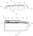
- FIG. 5 schematically illustrates a further example of a nacelle with displaceable roof panels.
- a nacelle 16 for a wind turbine which comprises a housing including a front side, and a rear side separated from the front side along an axial direction, a roof, a first sidewall, and a second sidewall.
- the roof comprises a plurality of roof panels, and wherein one or more of the roof panels are displaceable roof panels 230, 240 configured to be detached from neighbouring roof panels and from the first and second sidewalls.
- the nacelle is further configured to guide the displaceable roof panels 230, 240 in the axial direction.
- the example of figure 5 generally functions similarly as the example of figure 4 .
- the example of figure 5 is different from the example of figure 4 in that the roof bracket comprises a hinge allowing tilting of an upper part of the roof bracket with respect to a lower part of the roof bracket. This is illustrated in more detail in in figure 5B .
- the displaceable roof panels may comprise a first and second slider 360 as before, and the sliders may be arranged at or near a bottom of the roof brackets to mate with a guide or rails 310 of the side brackets.
- the roof bracket 350 comprises an upper part 352 which comprises a U-shaped flange 358 to receive a bottom edge of a roof panel.
- the roof bracket 350 of this example further comprises a lower part 354.
- the upper part 358 is hingedly connected to the lower part 354 such that the upper part 358 can tilt with respect to the lower part.
- the displaceable roof panels do not follow a linear (horizontal) path completely supported by rails. Rather, due to the shape of the nacelle, the path of the displaceable roof panels may have portions that are at an angle with neighbouring portions.
- one of the displaceable roof panels comprises a first and second slider 360, and wherein the first sidewall comprise a first rail 310 to guide the first slider 360, and the second sidewall comprises a second rail to guide the second slider.
- the slider 360 may be configured to rotate with respect to the displaceable roof panel.
- a hinge 370 between the upper and lower parts 358, 354 of the roof bracket allows the slider 360 to tilt or rotate with respect to the roof panel and adjust for differing inclinations along its path.
- a limited amount of rotation e.g. less than 25o in either direction is allowed, and specifically less than 20o. Stoppers may be provided to limit the amount of rotation in either direction.
- the roof bracket 350 may further comprise mounting holes 353 for removably mounting slider 360. If the slider 360 needs to be replaced or repaired, it may easily be removed. Furthermore, in this example, roof bracket 350 comprises a possibility to adjust a preload on the sliders or e.g. the wheels of the sliders. Holes 359 provided in this example in the lower part 354 of roof bracket 350 at a height at which the slider 360 may be mounted. In the shown examples, bolts extending through holes 359 may be used to adjust a preload. Adjusting a preloading may be useful e.g. when a rail 310 or raceway is substituted or changed for another.
- Figure 5C further illustrates the attachment of side bracket 300 with rail 310 and a how a U-shaped flange 305 may receive a top edge 265 of a sidewall of the housing of the nacelle.
- Figure 5C further illustrates the mounting of the roof bracket and the hinge 370 allowing tilting of the upper part 358 of the roof bracket with respect to a lower part 354 of the roof bracket.
- a displaceable roof panel in the example of figure 5 may comprise an additional support at or near an end of the roof panel.
- the additional support may include one or more wheels which allow the displaceable roof panel to roll over neighbouring roof panels. I.e. the weight of the roof panel is supported in the rails and side brackets, but also by the additional support.
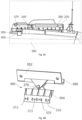
- Figure 6 schematically illustrates an alternative example of a mechanism for displacing roof panels.
- Figure 6 shows an alternative example of a roof bracket 350 which may be attached to a displaceable roof panel.
- the bottom part 354 of the roof bracket 350 may incorporate a guided element such as a slider.
- the upper part 352 of the roof bracket 350 may again be configured to be attached to the displaceable roof panel and to support the roof panel.
- an alternative hinge 372 comprising a scissor like structure including legs that are connected at a central point. Each of the legs comprises a slot like structure along which the central connection point may be displaced to allow for tilting.
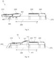
- Figure 7 schematically illustrates a further example of a nacelle.
- first and second displaceable roof panels may be displaced as a unit. I.e. between them they remain attached.
- a first displaceable roof panel 230 is configured to be displaced forwards
- the second displaceable roof panel 220 is configured to be displaced rearwards.
- roof panel 230 rests over a neighbouring front roof panel 240 in its most forward position
- roof panel 220 rests over a neighbouring rear roof panel 210 in its most rearward position.
- first and second displaceable roof panels may be displaced in the same axial direction (particularly rearwards) but move independently from one another.
- the first displaceable roof panel may be placed over the second displaceable roof panel when both roof panels have been displaced to their rest positions e.g. their most rearward positions.
- FIG. 8 schematically illustrates a further example of a wind turbine nacelle.
- the nacelle 16 once again includes sidewalls, of which a first sidewall 260 is visible this side view, a front or upstream side 270 and a rear or downstream side 250.
- the housing of the nacelle 16 further comprises a plurality of roof panels, 210, 220, 230 and 240.
- roof panels 220, 230, 240 are displaceable roof panels and they may be displaced along an axial direction, and more particularly they may be displaced rearwards.
- displaceable roof panels 220, 230, 240 may be displaced as a unit, i.e. they remain attached to each other at all times. In order to displace them, the roof panels 220,230, 240 may be detached from neighbouring portions of the nacelle and lifted.
- a rail may be attached to the nacelle, and particularly to the sidewalls of the nacelle housing.
- Roof brackets may be attached as herein before illustrated and these roof brackets may include sliders or alternatively rolling elements configured to be received in the rail.
- the rail 310 in this example may be substantially completely linear and horizontal.
- the rail 310 may be supported through a plurality of side brackets attached to the sidewalls of the housing, particularly along portions of the sidewall where the roof panels have been lifted.
- the rail may further be supported at supports 402, 404 on a rear portion of the nacelle. These supports may be attached at an outside of the nacelle, contrary to the side brackets arranged along the more forward parts of the nacelle.
- the rail 310 extends beyond the rear end of the nacelle in a manner such that the roof panels 220, 230, 240 may be moved in a rearwards direction such that at least roof panel 220 reaches beyond a rear end of the nacelle.
- the roof panels 240, 230, 220 may be displaced rearwardly to an extent that the roof of the nacelle is open along the entire length of the panels 220, 230, 240.
- a rail was mentioned as a guiding element, it should be clear that in other examples, other guiding elements might be used including e.g. bearings, raceways, bushings or other.
- FIG 9 schematically illustrates a wind turbine nacelle according to a further example.
- the nacelle 16 includes a telescopic mechanism.
- the telescopic mechanism may comprise a guiding element (e.g. a base rail 802) and a guided element, e.g. further rail portions 804, 806.
- a guiding element e.g. a base rail 802
- a guided element e.g. further rail portions 804, 806.
- One of the further rail portions 806 may be attached to a displaceable roof panel.
- the telescopic mechanism may be partially of fully extended in a first direction (e.g. towards a front of the nacelle), and a base of the telescopic mechanism may be attached to a sidewall 260 of the housing of the nacelle.
- the displaceable roof panel(s) 210 may be separated from other portions of the housing and the telescopic mechanism may be extended in an opposite direction (e.g. in a rearwards direction of the nacelle) to displace the displaceable roof panel along the axial direction.
- FIG 10 illustrates yet a further example of a nacelle 16.
- the nacelle 16 in this example comprises roof panels 210, 220, 230, 240.
- the displaceable roof panel 220 can be lifted and displaced in an axial direction x.
- the displaceable roof panel 220 may be displaced in a forward direction.
- the roof panel 230 which is neighbouring to displaceable roof panel 220 may comprise a plurality of rollers 410.
- the roof panel 230 may be lifted from an inside of the nacelle.
- a hydraulic jack like a hydraulic scissor jack 250 may be used.
- the hydraulic jack may include a roller or wheel. After lifting the displaceable roof panel 220, the roof panel may be pushed in the axial direction and further slide over rollers 420 incorporated in a neighbouring panel.
Landscapes
- Engineering & Computer Science (AREA)
- Life Sciences & Earth Sciences (AREA)
- Sustainable Development (AREA)
- Sustainable Energy (AREA)
- Chemical & Material Sciences (AREA)
- Combustion & Propulsion (AREA)
- Mechanical Engineering (AREA)
- General Engineering & Computer Science (AREA)
- Wind Motors (AREA)
Claims (11)
- Eine Windturbinengondel (16), die Folgendes umfasst:ein Gehäuse mit einer Vorderseite (270) und einer Rückseite (250), die von der Vorderseite entlang einer axialen Richtung (x) getrennt ist, ersten und zweiten Seitenwänden (260), die sich von der Vorderseite zur Rückseite erstrecken, und einem Dach, wobeidas Dach eine oder mehrere Dachplatten (210, 220, 230, 240) umfasst, und wobeimindestens eine der Dachplatten eine verschiebbare Dachplatte ist, die so konfiguriert ist, dass sie entlang der axialen Richtung (x) in Bezug auf einen anderen Teil des Daches verschoben werden kann, um einen Zugang zu der Gondel (16) von oben zu ermöglichen, wobeidie ersten und zweiten Seitenwände (260) erste und zweite Führungselemente (310) umfassen, und wobei die verschiebbare Dachplatte erste und zweite gefühtre elemente (360) umfasst, die so konfiguriert sind, dass sie durch die ersten bzw. zweiten Führungselemente (310) geführt werden, wobeidie erste Seitenwand (260) eine erste Seitenhalterung (300) umfasst, die eines der Führungselemente (310) trägt, und die zweite Seitenwand eine zweite Seitenhalterung umfasst, die ein anderes der Führungselemente trägt, und die verschiebbare Dachplatte eine Dachhalterung (350) umfasst, wobei das geführte Element an oder in der Nähe eines unteren Endes der Dachhalterung angeordnet ist, und wobei die Dachhalterung (350) ein Scharnier (370) umfasst, das ein Kippen eines oberen Teils (352) der Dachhalterung in Bezug auf einen unteren Teil (354) der Dachhalterung ermöglicht.
- Windturbinengondel nach Anspruch 1, wobei die verschiebbare Dachplatte so gestaltet ist, dass sie nach hinten verschoben werden kann.
- Windturbinengondel nach Anspruch 1 oder 2, wobei die ersten und zweiten Führungselemente Schienen (310) sind und wobei die geführten Elemente Gleiter (360) sind, die so konfiguriert sind, dass sie in den Schienen aufgenommen werden können.
- Windturbinengondel nach einem der Ansprüche 1 bis 3, die eine erste (230) und eine zweite (220) verschiebbare Dachplatte umfasst, die so konfiguriert sind, dass sie entlang der axialen Richtung verschoben werden können.
- Windturbinengondel nach Anspruch 4, wobei die erste und die zweite verschiebbare Dachplatte (230, 220) so konfiguriert sind, dass sie nach hinten verschoben werden können.
- Windturbinengondel nach Anspruch 5, wobei die erste verschiebbare Dachplatte (230) so konfiguriert ist, dass sie nach vorne verschoben wird, und die zweite verschiebbare Dachplatte (220) so konfiguriert ist, dass sie nach hinten verschoben wird.
- Windturbinengondel nach Anspruch 6, wobei das erste verschiebbare Dachplatte über dem zweiten verschiebbaren Dachplatte platziert wird, wenn beide Dachplatten in ihre hintersten Positionen verschoben worden sind.
- Eine Windturbine (10), die die Windturbinengondel (16) nach einem der Ansprüche 1 bis 7 umfasst.
- Verfahren zur Schaffung eines Zugangs zum Inneren einer Windturbinengondel (16), das Folgendes umfasst:Lösen einer verschiebbaren Dachplatte (220, 230) von anderen Teilen eines Daches der Gondel (16);Anheben der verschiebbaren Dachplatte (220, 230) aus dem Inneren der Gondel;nach dem Anheben der verschiebbaren Dachplatte (220, 320), Anbringen einer ersten Seitenhalterung (300) an einer ersten Seitenwand (260) der Gondel (16) und Anbringen einer zweiten Seitenhalterung an einer zweiten Seitenwand der Gondel, wobei die erste und die zweite Seitenhalterung (300) Führungselemente (310) zum Führen der verschiebbaren Dachplatte umfassen; undVerschieben der verschiebbaren Dachplatte in Richtung einer Vorderseite (270) oder einer Rückseite (250) der Gondel (16).
- Verfahren nach Anspruch 9, wobei die erste und die zweite Halterung an einer Oberseite (265) der ersten und der zweiten Seitenwand (260) angebracht sind.
- Verfahren nach Anspruch 9 oder 10 umfasst ferner:
Anbringen eines ersten und eines zweiten Dachträgers (350) an der verschiebbaren Dachplatte, wobei der erste und der zweite Dachträger einen Schieber (360) umfassen, der so konfiguriert ist, dass er durch die Führungselemente (310) des ersten und des zweiten Seitenträgers geführt wird.
Priority Applications (5)
| Application Number | Priority Date | Filing Date | Title |
|---|---|---|---|
| ES21382800T ES3002336T3 (en) | 2021-09-06 | 2021-09-06 | Wind turbine nacelle with at least one displaceable roof panel |
| EP21382800.7A EP4144986B1 (de) | 2021-09-06 | 2021-09-06 | Windturbinengondel mit mindestens einer verschiebbaren dachplatte |
| DK21382800.7T DK4144986T3 (da) | 2021-09-06 | 2021-09-06 | Vindmøllenacelle med mindst ét forskydeligt tagpanel |
| US17/902,155 US12025105B2 (en) | 2021-09-06 | 2022-09-02 | Wind turbine nacelles |
| CN202211086563.8A CN115773205A (zh) | 2021-09-06 | 2022-09-06 | 风力涡轮机舱 |
Applications Claiming Priority (1)
| Application Number | Priority Date | Filing Date | Title |
|---|---|---|---|
| EP21382800.7A EP4144986B1 (de) | 2021-09-06 | 2021-09-06 | Windturbinengondel mit mindestens einer verschiebbaren dachplatte |
Publications (2)
| Publication Number | Publication Date |
|---|---|
| EP4144986A1 EP4144986A1 (de) | 2023-03-08 |
| EP4144986B1 true EP4144986B1 (de) | 2024-11-06 |
Family
ID=77914259
Family Applications (1)
| Application Number | Title | Priority Date | Filing Date |
|---|---|---|---|
| EP21382800.7A Active EP4144986B1 (de) | 2021-09-06 | 2021-09-06 | Windturbinengondel mit mindestens einer verschiebbaren dachplatte |
Country Status (5)
| Country | Link |
|---|---|
| US (1) | US12025105B2 (de) |
| EP (1) | EP4144986B1 (de) |
| CN (1) | CN115773205A (de) |
| DK (1) | DK4144986T3 (de) |
| ES (1) | ES3002336T3 (de) |
Citations (2)
| Publication number | Priority date | Publication date | Assignee | Title |
|---|---|---|---|---|
| WO2022090061A1 (en) * | 2020-10-29 | 2022-05-05 | Jupiter Bach A/S | Nacelle for a wind turbine |
| EP4047205A1 (de) * | 2021-02-19 | 2022-08-24 | Siemens Gamesa Renewable Energy A/S | Schiebedachsystem für eine gondel |
Family Cites Families (36)
| Publication number | Priority date | Publication date | Assignee | Title |
|---|---|---|---|---|
| NL8201283A (nl) | 1982-03-26 | 1983-10-17 | Fdo Techn Adviseurs | Deelbare gondel voor een windmolen. |
| US4757211A (en) * | 1987-07-10 | 1988-07-12 | Danregn Vidraft A/S | Machine for generating electricity |
| ES2316200B1 (es) | 2004-12-21 | 2010-01-11 | GAMESA INNOVATION & TECHNOLOGY, S.L. | Aerogenerador con grua desmontable y pescante auxiliar y procedimiento de montaje de dicha grua. |
| FR2905357B1 (fr) | 2006-08-31 | 2009-07-03 | Aircelle Sa | Systeme de verrouillage pour capot mobile de nacelle |
| JP4885071B2 (ja) | 2007-06-19 | 2012-02-29 | 三菱重工業株式会社 | 風車用設備の交換方法 |
| WO2009132671A2 (de) * | 2008-04-30 | 2009-11-05 | Multibird Gmbh | Verkleidung einer gondel einer windenergieanlage |
| DE102008027498A1 (de) | 2008-06-10 | 2009-12-17 | Kenersys Gmbh | Gehäuse für die Gondel einer Windenergieanlage |
| KR101038641B1 (ko) | 2008-09-01 | 2011-06-03 | 두산중공업 주식회사 | 풍력터빈설비의 유지 보수 시스템 |
| DE102008047769B4 (de) | 2008-09-17 | 2013-04-11 | Suzlon Energy Gmbh | Hubvorrichtung für eine Windturbine |
| US7845693B2 (en) | 2008-10-10 | 2010-12-07 | General Electric Company | Hatch stop for wind turbines |
| US20100232977A1 (en) | 2009-03-13 | 2010-09-16 | Vestas Wind Systems A/S | Height Adjustable Wind Turbine Nacelle |
| FR2946094B1 (fr) | 2009-06-02 | 2014-04-18 | Aircelle Sa | Inverseur de poussee pour nacelle de turboreacteur double flux. |
| DK2363598T3 (en) | 2010-02-26 | 2018-12-17 | Siemens Ag | Windmill |
| IT1399511B1 (it) | 2010-04-22 | 2013-04-19 | Wilic Sarl | Generatore elettrico per un aerogeneratore e aerogeneratore equipaggiato con tale generatore elettrico |
| DK2395238T3 (da) | 2010-06-10 | 2014-04-22 | Siemens Ag | Vindmølle med et lynbeskyttelsessystem |
| US9677543B2 (en) | 2010-11-01 | 2017-06-13 | Mitsubishi Heavy Industries, Ltd. | Structure for nacelle cover connection portion of wind turbine generator |
| ES2593967T3 (es) | 2010-12-15 | 2016-12-14 | Vestas Wind Systems A/S | Una herramienta y un método para mover un componente del tren de transmisión de una turbina eólica |
| PL2469074T3 (pl) * | 2010-12-27 | 2016-12-30 | Instalacja wiatrowa z platformą do załadunku helikoptera | |
| WO2012105971A1 (en) * | 2011-02-02 | 2012-08-09 | Smith Matthew K | Nacelle-mounted maintenance system for wind turbines |
| CN105508154B (zh) * | 2011-02-07 | 2018-02-13 | 菱重维斯塔斯海上风力有限公司 | 具有直升机平台装置的风轮机及其使用方法 |
| RU2458246C1 (ru) | 2011-03-31 | 2012-08-10 | Александр Владимирович Губанов | Ветроэнергоблок стабилизирующий |
| WO2013075717A2 (en) | 2011-11-25 | 2013-05-30 | Vestas Wind Systems A/S | A tool and a method for moving a wind turbine drivetrain component |
| US9783315B2 (en) | 2012-02-24 | 2017-10-10 | Rohr, Inc. | Nacelle with longitudinal translating cowling and rotatable sleeves |
| DK178900B1 (da) * | 2012-06-04 | 2017-05-08 | Liftra Ip Aps | Fremgangsmåde og midler til etablering af adkomst til hoveddelene i nacellen på en vindmølle |
| CA2926249C (en) | 2013-10-04 | 2022-07-12 | Inventus Holdings, Llc | Uptower wind turbine component replacement |
| CN106414997B (zh) * | 2013-11-27 | 2018-11-23 | 维斯塔斯风力系统有限公司 | 用于风轮发电机的包括提升设备的机舱 |
| DE102014216244A1 (de) | 2014-08-15 | 2016-03-03 | Siemens Aktiengesellschaft | Verfahren zum Austausch eines Wälzlagers und Verfahren zum axialen Verschieben eines WKA-Getriebes |
| DK3242014T3 (da) | 2016-05-02 | 2019-12-02 | Nordex Energy Gmbh | Nacellebeklædning til et vindenergianlæg |
| WO2018054437A1 (en) * | 2016-09-21 | 2018-03-29 | Vestas Wind Systems A/S | A method for opening a cover portion of a wind turbine |
| BR112019005699B1 (pt) | 2016-09-23 | 2022-10-25 | Leunamme Engineering S.L.U | Método e equipamento para substituir componentes de turbina eólica |
| EP3372730A1 (de) | 2017-03-07 | 2018-09-12 | Adwen GmbH | Klappen von einer gondel und helikopterhebebühne |
| CA3012945C (en) | 2017-11-22 | 2019-05-21 | LiftWerx Holdings Inc. | Lift system mountable in a nacelle of a wind turbine |
| CN107725284B (zh) | 2017-11-24 | 2024-03-12 | 国电联合动力技术有限公司 | 一种拉索式风电机组机舱吊物孔盖 |
| EP3611372A1 (de) | 2018-08-13 | 2020-02-19 | youWINenergy GmbH | Gondel für eine windkraftanlage, windkraftanlage mit der gondel und verfahren zur montage der windturbinenanlage |
| EP3870850B1 (de) * | 2018-10-24 | 2023-11-22 | LiftWerx Holdings Inc. | Hebesystem zum öffnen eines oberen teils einer gondel |
| CN110805516A (zh) | 2019-12-07 | 2020-02-18 | 大连理工大学 | 基于多气室振荡水柱装置的波浪能-风能集成发电系统 |
-
2021
- 2021-09-06 EP EP21382800.7A patent/EP4144986B1/de active Active
- 2021-09-06 DK DK21382800.7T patent/DK4144986T3/da active
- 2021-09-06 ES ES21382800T patent/ES3002336T3/es active Active
-
2022
- 2022-09-02 US US17/902,155 patent/US12025105B2/en active Active
- 2022-09-06 CN CN202211086563.8A patent/CN115773205A/zh active Pending
Patent Citations (2)
| Publication number | Priority date | Publication date | Assignee | Title |
|---|---|---|---|---|
| WO2022090061A1 (en) * | 2020-10-29 | 2022-05-05 | Jupiter Bach A/S | Nacelle for a wind turbine |
| EP4047205A1 (de) * | 2021-02-19 | 2022-08-24 | Siemens Gamesa Renewable Energy A/S | Schiebedachsystem für eine gondel |
Also Published As
| Publication number | Publication date |
|---|---|
| US20230072624A1 (en) | 2023-03-09 |
| US12025105B2 (en) | 2024-07-02 |
| DK4144986T3 (da) | 2025-02-03 |
| CN115773205A (zh) | 2023-03-10 |
| EP4144986A1 (de) | 2023-03-08 |
| ES3002336T3 (en) | 2025-03-06 |
Similar Documents
| Publication | Publication Date | Title |
|---|---|---|
| US7969037B2 (en) | Configuration of a wind turbine nacelle | |
| EP1859165B1 (de) | Gondel einer windenergieanlage mit eingebautem wartungskran zum zugriff auf turbinenteile | |
| EP2635804B1 (de) | Windenergieanlage | |
| US20090250939A1 (en) | Wind-driven generation of power | |
| US10443572B2 (en) | System and method for removing or installing a main shaft of a wind turbine | |
| US12006910B2 (en) | Assemblies for wind turbines and methods | |
| EP4144986B1 (de) | Windturbinengondel mit mindestens einer verschiebbaren dachplatte | |
| CN112983763B (zh) | 防止人员暴露于由风力涡轮表面限定的开口的组件和方法 | |
| US20230323860A1 (en) | Wind turbine frame with flexible coupling | |
| US20240018944A1 (en) | Cabins and methods for wind turbine maintenance | |
| US20250003396A1 (en) | Methods for extracting transformers of a nacelle of a wind turbine | |
| CN223316294U (zh) | 一种海上风力发电机更换齿轮箱部件的装置 | |
| EP3364023B1 (de) | System und verfahren zum entfernen oder installieren einer hauptwelle einer windturbine | |
| EP3615794B1 (de) | Vorrichtung und verfahren zum entfernen oder installieren einer lagereinheit bei einer windturbine mit verstellbarer lagerstütze | |
| WO2025002521A1 (en) | Improvements relating to wind turbine nacelles | |
| WO2025247493A1 (en) | Methods for installing wind turbine blades | |
| JP2025022227A (ja) | 重量物移動装置および重量物エレベーション調整方法 | |
| WO2025214581A1 (en) | Systems for aligning wind turbine blades and hubs and methods for mounting wind turbine blades | |
| WO2025247492A1 (en) | Methods, sets and blades for installation of a wind turbine blade | |
| KR20100090499A (ko) | 터어빈 부품 억세스용 일체형 서비스 크레인을 구비한 풍력터어빈 너셀 |
Legal Events
| Date | Code | Title | Description |
|---|---|---|---|
| PUAI | Public reference made under article 153(3) epc to a published international application that has entered the european phase |
Free format text: ORIGINAL CODE: 0009012 |
|
| STAA | Information on the status of an ep patent application or granted ep patent |
Free format text: STATUS: THE APPLICATION HAS BEEN PUBLISHED |
|
| AK | Designated contracting states |
Kind code of ref document: A1 Designated state(s): AL AT BE BG CH CY CZ DE DK EE ES FI FR GB GR HR HU IE IS IT LI LT LU LV MC MK MT NL NO PL PT RO RS SE SI SK SM TR |
|
| P01 | Opt-out of the competence of the unified patent court (upc) registered |
Effective date: 20230530 |
|
| STAA | Information on the status of an ep patent application or granted ep patent |
Free format text: STATUS: REQUEST FOR EXAMINATION WAS MADE |
|
| 17P | Request for examination filed |
Effective date: 20230908 |
|
| RBV | Designated contracting states (corrected) |
Designated state(s): AL AT BE BG CH CY CZ DE DK EE ES FI FR GB GR HR HU IE IS IT LI LT LU LV MC MK MT NL NO PL PT RO RS SE SI SK SM TR |
|
| STAA | Information on the status of an ep patent application or granted ep patent |
Free format text: STATUS: EXAMINATION IS IN PROGRESS |
|
| 17Q | First examination report despatched |
Effective date: 20240313 |
|
| REG | Reference to a national code |
Ref country code: DE Ref legal event code: R079 Free format text: PREVIOUS MAIN CLASS: F03D0080800000 Ipc: F03D0001000000 Ref country code: DE Ref legal event code: R079 Ref document number: 602021021365 Country of ref document: DE Free format text: PREVIOUS MAIN CLASS: F03D0080800000 Ipc: F03D0001000000 |
|
| GRAP | Despatch of communication of intention to grant a patent |
Free format text: ORIGINAL CODE: EPIDOSNIGR1 |
|
| STAA | Information on the status of an ep patent application or granted ep patent |
Free format text: STATUS: GRANT OF PATENT IS INTENDED |
|
| RIC1 | Information provided on ipc code assigned before grant |
Ipc: F03D 80/50 20160101ALI20240806BHEP Ipc: F03D 1/00 20060101AFI20240806BHEP |
|
| INTG | Intention to grant announced |
Effective date: 20240826 |
|
| GRAS | Grant fee paid |
Free format text: ORIGINAL CODE: EPIDOSNIGR3 |
|
| GRAA | (expected) grant |
Free format text: ORIGINAL CODE: 0009210 |
|
| STAA | Information on the status of an ep patent application or granted ep patent |
Free format text: STATUS: THE PATENT HAS BEEN GRANTED |
|
| AK | Designated contracting states |
Kind code of ref document: B1 Designated state(s): AL AT BE BG CH CY CZ DE DK EE ES FI FR GB GR HR HU IE IS IT LI LT LU LV MC MK MT NL NO PL PT RO RS SE SI SK SM TR |
|
| REG | Reference to a national code |
Ref country code: GB Ref legal event code: FG4D |
|
| REG | Reference to a national code |
Ref country code: CH Ref legal event code: EP |
|
| REG | Reference to a national code |
Ref country code: DE Ref legal event code: R096 Ref document number: 602021021365 Country of ref document: DE |
|
| REG | Reference to a national code |
Ref country code: IE Ref legal event code: FG4D |
|
| REG | Reference to a national code |
Ref country code: DK Ref legal event code: T3 Effective date: 20250127 |
|
| REG | Reference to a national code |
Ref country code: ES Ref legal event code: FG2A Ref document number: 3002336 Country of ref document: ES Kind code of ref document: T3 Effective date: 20250306 |
|
| REG | Reference to a national code |
Ref country code: LT Ref legal event code: MG9D |
|
| REG | Reference to a national code |
Ref country code: NL Ref legal event code: MP Effective date: 20241106 |
|
| PG25 | Lapsed in a contracting state [announced via postgrant information from national office to epo] |
Ref country code: PT Free format text: LAPSE BECAUSE OF FAILURE TO SUBMIT A TRANSLATION OF THE DESCRIPTION OR TO PAY THE FEE WITHIN THE PRESCRIBED TIME-LIMIT Effective date: 20250306 Ref country code: HR Free format text: LAPSE BECAUSE OF FAILURE TO SUBMIT A TRANSLATION OF THE DESCRIPTION OR TO PAY THE FEE WITHIN THE PRESCRIBED TIME-LIMIT Effective date: 20241106 Ref country code: IS Free format text: LAPSE BECAUSE OF FAILURE TO SUBMIT A TRANSLATION OF THE DESCRIPTION OR TO PAY THE FEE WITHIN THE PRESCRIBED TIME-LIMIT Effective date: 20250306 |
|
| PG25 | Lapsed in a contracting state [announced via postgrant information from national office to epo] |
Ref country code: FI Free format text: LAPSE BECAUSE OF FAILURE TO SUBMIT A TRANSLATION OF THE DESCRIPTION OR TO PAY THE FEE WITHIN THE PRESCRIBED TIME-LIMIT Effective date: 20241106 Ref country code: NL Free format text: LAPSE BECAUSE OF FAILURE TO SUBMIT A TRANSLATION OF THE DESCRIPTION OR TO PAY THE FEE WITHIN THE PRESCRIBED TIME-LIMIT Effective date: 20241106 |
|
| REG | Reference to a national code |
Ref country code: AT Ref legal event code: MK05 Ref document number: 1739580 Country of ref document: AT Kind code of ref document: T Effective date: 20241106 |
|
| PG25 | Lapsed in a contracting state [announced via postgrant information from national office to epo] |
Ref country code: BG Free format text: LAPSE BECAUSE OF FAILURE TO SUBMIT A TRANSLATION OF THE DESCRIPTION OR TO PAY THE FEE WITHIN THE PRESCRIBED TIME-LIMIT Effective date: 20241106 |
|
| PG25 | Lapsed in a contracting state [announced via postgrant information from national office to epo] |
Ref country code: NO Free format text: LAPSE BECAUSE OF FAILURE TO SUBMIT A TRANSLATION OF THE DESCRIPTION OR TO PAY THE FEE WITHIN THE PRESCRIBED TIME-LIMIT Effective date: 20250206 |
|
| PG25 | Lapsed in a contracting state [announced via postgrant information from national office to epo] |
Ref country code: LV Free format text: LAPSE BECAUSE OF FAILURE TO SUBMIT A TRANSLATION OF THE DESCRIPTION OR TO PAY THE FEE WITHIN THE PRESCRIBED TIME-LIMIT Effective date: 20241106 Ref country code: GR Free format text: LAPSE BECAUSE OF FAILURE TO SUBMIT A TRANSLATION OF THE DESCRIPTION OR TO PAY THE FEE WITHIN THE PRESCRIBED TIME-LIMIT Effective date: 20250207 Ref country code: AT Free format text: LAPSE BECAUSE OF FAILURE TO SUBMIT A TRANSLATION OF THE DESCRIPTION OR TO PAY THE FEE WITHIN THE PRESCRIBED TIME-LIMIT Effective date: 20241106 |
|
| PG25 | Lapsed in a contracting state [announced via postgrant information from national office to epo] |
Ref country code: PL Free format text: LAPSE BECAUSE OF FAILURE TO SUBMIT A TRANSLATION OF THE DESCRIPTION OR TO PAY THE FEE WITHIN THE PRESCRIBED TIME-LIMIT Effective date: 20241106 |
|
| PG25 | Lapsed in a contracting state [announced via postgrant information from national office to epo] |
Ref country code: RS Free format text: LAPSE BECAUSE OF FAILURE TO SUBMIT A TRANSLATION OF THE DESCRIPTION OR TO PAY THE FEE WITHIN THE PRESCRIBED TIME-LIMIT Effective date: 20250206 |
|
| PG25 | Lapsed in a contracting state [announced via postgrant information from national office to epo] |
Ref country code: SM Free format text: LAPSE BECAUSE OF FAILURE TO SUBMIT A TRANSLATION OF THE DESCRIPTION OR TO PAY THE FEE WITHIN THE PRESCRIBED TIME-LIMIT Effective date: 20241106 |
|
| PG25 | Lapsed in a contracting state [announced via postgrant information from national office to epo] |
Ref country code: EE Free format text: LAPSE BECAUSE OF FAILURE TO SUBMIT A TRANSLATION OF THE DESCRIPTION OR TO PAY THE FEE WITHIN THE PRESCRIBED TIME-LIMIT Effective date: 20241106 |
|
| PG25 | Lapsed in a contracting state [announced via postgrant information from national office to epo] |
Ref country code: RO Free format text: LAPSE BECAUSE OF FAILURE TO SUBMIT A TRANSLATION OF THE DESCRIPTION OR TO PAY THE FEE WITHIN THE PRESCRIBED TIME-LIMIT Effective date: 20241106 |
|
| PG25 | Lapsed in a contracting state [announced via postgrant information from national office to epo] |
Ref country code: SK Free format text: LAPSE BECAUSE OF FAILURE TO SUBMIT A TRANSLATION OF THE DESCRIPTION OR TO PAY THE FEE WITHIN THE PRESCRIBED TIME-LIMIT Effective date: 20241106 |
|
| PG25 | Lapsed in a contracting state [announced via postgrant information from national office to epo] |
Ref country code: CZ Free format text: LAPSE BECAUSE OF FAILURE TO SUBMIT A TRANSLATION OF THE DESCRIPTION OR TO PAY THE FEE WITHIN THE PRESCRIBED TIME-LIMIT Effective date: 20241106 |
|
| PG25 | Lapsed in a contracting state [announced via postgrant information from national office to epo] |
Ref country code: IT Free format text: LAPSE BECAUSE OF FAILURE TO SUBMIT A TRANSLATION OF THE DESCRIPTION OR TO PAY THE FEE WITHIN THE PRESCRIBED TIME-LIMIT Effective date: 20241106 |
|
| REG | Reference to a national code |
Ref country code: DE Ref legal event code: R097 Ref document number: 602021021365 Country of ref document: DE |
|
| PG25 | Lapsed in a contracting state [announced via postgrant information from national office to epo] |
Ref country code: SE Free format text: LAPSE BECAUSE OF FAILURE TO SUBMIT A TRANSLATION OF THE DESCRIPTION OR TO PAY THE FEE WITHIN THE PRESCRIBED TIME-LIMIT Effective date: 20241106 |
|
| PLBE | No opposition filed within time limit |
Free format text: ORIGINAL CODE: 0009261 |
|
| STAA | Information on the status of an ep patent application or granted ep patent |
Free format text: STATUS: NO OPPOSITION FILED WITHIN TIME LIMIT |
|
| PGFP | Annual fee paid to national office [announced via postgrant information from national office to epo] |
Ref country code: DK Payment date: 20250820 Year of fee payment: 5 Ref country code: DE Payment date: 20250820 Year of fee payment: 5 |
|
| 26N | No opposition filed |
Effective date: 20250807 |
|
| PGFP | Annual fee paid to national office [announced via postgrant information from national office to epo] |
Ref country code: ES Payment date: 20251001 Year of fee payment: 5 |