EP4144970B1 - Flüssige wasserstoffverdampfer und heizgeräte - Google Patents
Flüssige wasserstoffverdampfer und heizgeräte Download PDFInfo
- Publication number
- EP4144970B1 EP4144970B1 EP22189996.6A EP22189996A EP4144970B1 EP 4144970 B1 EP4144970 B1 EP 4144970B1 EP 22189996 A EP22189996 A EP 22189996A EP 4144970 B1 EP4144970 B1 EP 4144970B1
- Authority
- EP
- European Patent Office
- Prior art keywords
- gaseous hydrogen
- engine
- working fluid
- heater
- gas turbine
- Prior art date
- Legal status (The legal status is an assumption and is not a legal conclusion. Google has not performed a legal analysis and makes no representation as to the accuracy of the status listed.)
- Active
Links
Images


Classifications
-
- F—MECHANICAL ENGINEERING; LIGHTING; HEATING; WEAPONS; BLASTING
- F02—COMBUSTION ENGINES; HOT-GAS OR COMBUSTION-PRODUCT ENGINE PLANTS
- F02C—GAS-TURBINE PLANTS; AIR INTAKES FOR JET-PROPULSION PLANTS; CONTROLLING FUEL SUPPLY IN AIR-BREATHING JET-PROPULSION PLANTS
- F02C3/00—Gas-turbine plants characterised by the use of combustion products as the working fluid
- F02C3/20—Gas-turbine plants characterised by the use of combustion products as the working fluid using a special fuel, oxidant, or dilution fluid to generate the combustion products
- F02C3/22—Gas-turbine plants characterised by the use of combustion products as the working fluid using a special fuel, oxidant, or dilution fluid to generate the combustion products the fuel or oxidant being gaseous at standard temperature and pressure
-
- F—MECHANICAL ENGINEERING; LIGHTING; HEATING; WEAPONS; BLASTING
- F02—COMBUSTION ENGINES; HOT-GAS OR COMBUSTION-PRODUCT ENGINE PLANTS
- F02C—GAS-TURBINE PLANTS; AIR INTAKES FOR JET-PROPULSION PLANTS; CONTROLLING FUEL SUPPLY IN AIR-BREATHING JET-PROPULSION PLANTS
- F02C3/00—Gas-turbine plants characterised by the use of combustion products as the working fluid
- F02C3/20—Gas-turbine plants characterised by the use of combustion products as the working fluid using a special fuel, oxidant, or dilution fluid to generate the combustion products
-
- F—MECHANICAL ENGINEERING; LIGHTING; HEATING; WEAPONS; BLASTING
- F02—COMBUSTION ENGINES; HOT-GAS OR COMBUSTION-PRODUCT ENGINE PLANTS
- F02C—GAS-TURBINE PLANTS; AIR INTAKES FOR JET-PROPULSION PLANTS; CONTROLLING FUEL SUPPLY IN AIR-BREATHING JET-PROPULSION PLANTS
- F02C6/00—Plural gas-turbine plants; Combinations of gas-turbine plants with other apparatus; Adaptations of gas-turbine plants for special use
- F02C6/04—Gas-turbine plants providing heated or pressurised working fluid for other apparatus, e.g. without mechanical power output
- F02C6/06—Gas-turbine plants providing heated or pressurised working fluid for other apparatus, e.g. without mechanical power output providing compressed gas
- F02C6/08—Gas-turbine plants providing heated or pressurised working fluid for other apparatus, e.g. without mechanical power output providing compressed gas the gas being bled from the gas-turbine compressor
-
- F—MECHANICAL ENGINEERING; LIGHTING; HEATING; WEAPONS; BLASTING
- F02—COMBUSTION ENGINES; HOT-GAS OR COMBUSTION-PRODUCT ENGINE PLANTS
- F02C—GAS-TURBINE PLANTS; AIR INTAKES FOR JET-PROPULSION PLANTS; CONTROLLING FUEL SUPPLY IN AIR-BREATHING JET-PROPULSION PLANTS
- F02C6/00—Plural gas-turbine plants; Combinations of gas-turbine plants with other apparatus; Adaptations of gas-turbine plants for special use
- F02C6/04—Gas-turbine plants providing heated or pressurised working fluid for other apparatus, e.g. without mechanical power output
- F02C6/10—Gas-turbine plants providing heated or pressurised working fluid for other apparatus, e.g. without mechanical power output supplying working fluid to a user, e.g. a chemical process, which returns working fluid to a turbine of the plant
-
- F—MECHANICAL ENGINEERING; LIGHTING; HEATING; WEAPONS; BLASTING
- F02—COMBUSTION ENGINES; HOT-GAS OR COMBUSTION-PRODUCT ENGINE PLANTS
- F02C—GAS-TURBINE PLANTS; AIR INTAKES FOR JET-PROPULSION PLANTS; CONTROLLING FUEL SUPPLY IN AIR-BREATHING JET-PROPULSION PLANTS
- F02C7/00—Features, components parts, details or accessories, not provided for in, or of interest apart form groups F02C1/00 - F02C6/00; Air intakes for jet-propulsion plants
- F02C7/12—Cooling of plants
- F02C7/14—Cooling of plants of fluids in the plant, e.g. lubricant or fuel
-
- F—MECHANICAL ENGINEERING; LIGHTING; HEATING; WEAPONS; BLASTING
- F02—COMBUSTION ENGINES; HOT-GAS OR COMBUSTION-PRODUCT ENGINE PLANTS
- F02C—GAS-TURBINE PLANTS; AIR INTAKES FOR JET-PROPULSION PLANTS; CONTROLLING FUEL SUPPLY IN AIR-BREATHING JET-PROPULSION PLANTS
- F02C7/00—Features, components parts, details or accessories, not provided for in, or of interest apart form groups F02C1/00 - F02C6/00; Air intakes for jet-propulsion plants
- F02C7/22—Fuel supply systems
- F02C7/224—Heating fuel before feeding to the burner
-
- F—MECHANICAL ENGINEERING; LIGHTING; HEATING; WEAPONS; BLASTING
- F02—COMBUSTION ENGINES; HOT-GAS OR COMBUSTION-PRODUCT ENGINE PLANTS
- F02C—GAS-TURBINE PLANTS; AIR INTAKES FOR JET-PROPULSION PLANTS; CONTROLLING FUEL SUPPLY IN AIR-BREATHING JET-PROPULSION PLANTS
- F02C7/00—Features, components parts, details or accessories, not provided for in, or of interest apart form groups F02C1/00 - F02C6/00; Air intakes for jet-propulsion plants
- F02C7/32—Arrangement, mounting, or driving, of auxiliaries
-
- F—MECHANICAL ENGINEERING; LIGHTING; HEATING; WEAPONS; BLASTING
- F02—COMBUSTION ENGINES; HOT-GAS OR COMBUSTION-PRODUCT ENGINE PLANTS
- F02C—GAS-TURBINE PLANTS; AIR INTAKES FOR JET-PROPULSION PLANTS; CONTROLLING FUEL SUPPLY IN AIR-BREATHING JET-PROPULSION PLANTS
- F02C7/00—Features, components parts, details or accessories, not provided for in, or of interest apart form groups F02C1/00 - F02C6/00; Air intakes for jet-propulsion plants
- F02C7/36—Power transmission arrangements between the different shafts of the gas turbine plant, or between the gas-turbine plant and the power user
-
- F—MECHANICAL ENGINEERING; LIGHTING; HEATING; WEAPONS; BLASTING
- F02—COMBUSTION ENGINES; HOT-GAS OR COMBUSTION-PRODUCT ENGINE PLANTS
- F02C—GAS-TURBINE PLANTS; AIR INTAKES FOR JET-PROPULSION PLANTS; CONTROLLING FUEL SUPPLY IN AIR-BREATHING JET-PROPULSION PLANTS
- F02C9/00—Controlling gas-turbine plants; Controlling fuel supply in air- breathing jet-propulsion plants
- F02C9/26—Control of fuel supply
- F02C9/28—Regulating systems responsive to plant or ambient parameters, e.g. temperature, pressure, rotor speed
-
- F—MECHANICAL ENGINEERING; LIGHTING; HEATING; WEAPONS; BLASTING
- F05—INDEXING SCHEMES RELATING TO ENGINES OR PUMPS IN VARIOUS SUBCLASSES OF CLASSES F01-F04
- F05D—INDEXING SCHEME FOR ASPECTS RELATING TO NON-POSITIVE-DISPLACEMENT MACHINES OR ENGINES, GAS-TURBINES OR JET-PROPULSION PLANTS
- F05D2260/00—Function
- F05D2260/20—Heat transfer, e.g. cooling
- F05D2260/213—Heat transfer, e.g. cooling by the provision of a heat exchanger within the cooling circuit
-
- Y—GENERAL TAGGING OF NEW TECHNOLOGICAL DEVELOPMENTS; GENERAL TAGGING OF CROSS-SECTIONAL TECHNOLOGIES SPANNING OVER SEVERAL SECTIONS OF THE IPC; TECHNICAL SUBJECTS COVERED BY FORMER USPC CROSS-REFERENCE ART COLLECTIONS [XRACs] AND DIGESTS
- Y02—TECHNOLOGIES OR APPLICATIONS FOR MITIGATION OR ADAPTATION AGAINST CLIMATE CHANGE
- Y02T—CLIMATE CHANGE MITIGATION TECHNOLOGIES RELATED TO TRANSPORTATION
- Y02T50/00—Aeronautics or air transport
- Y02T50/40—Weight reduction
Definitions
- the fuel feed conduit is further defined by, in fluid series downstream of the evaporator, an accumulator, a pressure regulator, a gaseous hydrogen metering unit, a manifold shut-off valve, and a fuel manifold.
- an upstream working fluid conduit in fluid communication with the evaporator and defined at least in part by an electric heat source operative to add heat into the working fluid for heat exchange with the flow of hydrogen passing through the evaporator, and an upstream working fluid pump to drive the working fluid through the evaporator.
- the electric energy source is external to the gas turbine engine, and the electric energy source includes at least one of: an auxiliary power unit, an electric generator, and/or a battery operatively connected to power the electric heat source.
- the engine heat source is engine fluid.
- an engine fluid conduit defined at least in part by, in fluid series, an engine fluid source, the gaseous hydrogen heater, and an engine fluid return to add heat from the engine fluid to the flow of gaseous hydrogen passing through the gaseous hydrogen heater.
- the gaseous hydrogen heater is associated with an electric heat source to add heat to the flow of gaseous hydrogen passing through the gaseous hydrogen heater, wherein the electric heat source is external to, but powered by an electric energy module driven the gas turbine engine.
- a gear box operatively connected to be driven by a spool shaft of the gas turbine engine, wherein the electric energy source includes an electric generator operatively connected to be driven by the gear box to power the electric heat source associated with the gaseous hydrogen heater.
- a downstream working fluid conduit defined at least in part by, the gaseous hydrogen heater, the electric heat source to heat the downstream working fluid, a downstream working fluid pump to drive the downstream working fluid to the gaseous hydrogen heater to add heat to the flow of gaseous hydrogen passing through the gaseous hydrogen heater.
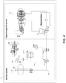
- FIG. 1 an illustrative view of an embodiment of a system in accordance with the disclosure is shown in Fig. 1 and is designated generally by reference character 100.
- FIGs. 2-6 Other embodiments and/or aspects of this disclosure are shown in Figs. 2-6 .
- Certain embodiments described herein can be used to improve conversion of liquid hydrogen fuel to gaseous hydrogen for combustion.
- an aircraft 1 can include an engine 10, where the engine 10 can be a propulsive energy engine (e.g. creating thrust for the aircraft 1), or a non-propulsive energy engine, and a fuel system 100.
- the engine 10 is a turbofan engine, although the present disclosure may likewise be used with other engine types.
- the engine 100 includes a compressor section 102 having a compressor 104 in a primary gas path 106 to supply compressed air to a combustor 108 of the aircraft engine 100.
- the primary gas path 106 includes a nozzle manifold 110 for issuing fluid to the combustor 108.
- the primary gas path 106 includes, in fluid communication in a series: the compressor 104, the combustor 108 fluidly connected to an outlet 114 of the compressor 104, and a turbine section 116 fluidly connected to an outlet 118 of the combustor 108.
- the turbine section 116 is mechanically connected to the compressor 104 to drive the compressor 104.
- the fuel system 100 includes the a evaporator/heater 134 where heat is supplued from any suitable heat source 144, for example engine fluid to evaporate/heat the liquid hydrogen therein.
- the evaporator/heater 134 can be an evaporator and/or a heater.
- the evaporator/heater 134 converts liquid hydrogen to gaseous hydrogen therein.
- the evaporator/heater 134 is only a heater, in which the heater 134 receives heated liquid from an external source to exchange heat with the liquid hydrogen therein, but does not necessarily evaporate the liquid hydrogen or may only evaporate some.
- the pump 132 is in fluid communication with the liquid hydrogen tank 124 to drive fuel from the liquid hydrogen tank 124 to the gas turbine engine 10 via the fuel feed conduit 122.
- An upstream working fluid conduit 248 is defined at least in part by an upstream heater circuit, which branches off of the fuel feed conduit 122.
- An electric heat source 244 e.g. a resistive heater
- the electric heat source 244 is in thermal communication with the upstream working fluid flowing through the upstream working fluid conduit 248 to add heat to the upstream working fluid.
- An electric energy source 246 is associated with the electric heat source 244 to power the electric heat source 244.
- the electric energy source can be external to the gas turbine engine 10, and can be or include at least one of: an auxiliary power unit 250, an electric generator 252, and/or a battery 254 operatively connected to power the electric source 244.
- a system 300 can have similar components as in system 200.
- the downstream heat source 360 is compressor bleed air from the compressor section 102.
- a bleed air conduit 362 fluidly connects the compressor section 102 with the gaseous hydrogen heater 358 to add heat from the compressor section 102 to the flow of gaseous hydrogen passing through the gaseous hydrogen heater 358.
- an environmental control system return conduit 364 conveys cooled compressor bleed air to an environmental control system (ECS) 366.
- ECS environmental control system
- a switching module can be disposed in the bleed air conduit 362 to allow the option of using either the low pressure compressor bleed air (e.g. lower temperature) as the downstream heat source 360) or high pressure compressor bleed air (e.g. higher temperature) as the downstream heat source 360, depending on the amount of heat needed for the gaseous hydrogen heater 358 and the amount of cooling air required for the ECS 366.
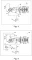
- a system 400 can have similar components as in system 200.
- the downstream heat source 460 can be turbine exhaust from a turbine exhaust section (e.g. turbine outlet 118) of the gas turbine engine 10.
- a downstream working fluid conduit 468 defines a downstream heater circuit which branches off the fuel feed conduit 122.
- the downstream working fluid conduit 468 is at least partially coiled (e.g. portion 468a) around the turbine exhaust section 118.
- a downstream working fluid pump 470 is disposed in the downstream working fluid conduit 468 to drive downstream working fluid through the downstream heater circuit, passing through the coiled portion 468a and to the gaseous hydrogen heater 458 to add heat to the flow of gaseous hydrogen passing through the gaseous hydrogen heater 458.
- the downstream working fluid conduit 468 is fluidly isolated from the flow of liquid hydrogen within the gaseous hydrogen heater 458 but is in thermal communication with the flow of hydrogen passing through the gaseous hydrogen heater 458 for exchanging heat from the downstream working fluid to the flow gaseous hydrogen passing through the gaseous hydrogen heater 458.
- a system 500 can have similar components as in system 200.
- the downstream heat source 560 is an engine fluid (e.g. engine oil).
- An engine fluid conduit is defined at least in part by an engine fluid feed conduit 572 and an engine fluid return conduit 574 fluidly connecting between the gas turbine engine 10 and the gaseous hydrogen heater 558 to convey the hot engine fluid from the engine 10 to the gaseous hydrogen heater 558 to add heat to the flow of gaseous hydrogen passing through the gaseous hydrogen heater 558.
- An engine pump 576 can be disposed in the compressor section 102 to drive the engine fluid from the engine 10 to the gaseous hydrogen heater 558.
- a downstream working fluid pump 670 is disposed in the downstream working fluid conduit 668 to drive downstream working fluid through the downstream heater circuit, passing through the electric heat source 678 to the gaseous hydrogen heater 658 to add heat to the flow of gaseous hydrogen passing through the gaseous hydrogen heater 658.
- the downstream working fluid conduit 668 is fluidly isolated from the flow of liquid hydrogen within the gaseous hydrogen heater 658 but is in thermal communication with the flow of hydrogen passing through the gaseous hydrogen heater 658 for exchanging heat from the downstream working fluid to the flow gaseous hydrogen passing through the gaseous hydrogen heater 658.
- the upstream heat source is external to a gas turbine engine (e.g. engine 10) and the downstream heat source is internal to the gas turbine engine.
- heating the flow of liquid hydrogen includes exchanging heat between an upstream heating working fluid in thermal communication with the upstream heat source and the flow of liquid hydrogen in the evaporator.
- the method includes powering the upstream heat source with at least one of an auxiliary power unit, an electric generator, and/or an electric energy module.
- heating the flow of gaseous hydrogen includes exchanging heat between an engine fluid and the flow of gaseous hydrogen in the gaseous hydrogen heater.
- the engine fluid includes at least compressor bleed air and, optionally, turbine exhaust, and/or engine oil.
- heating the flow of gaseous hydrogen includes exchanging heat between a downstream working fluid in thermal communication with the downstream heat source and the flow of gaseous hydrogen in the gaseous hydrogen heater.
- powering the downstream heat source with an electric generator (e.g. generator 684) driven by the gas turbine engine.
- liquid hydrogen can be pumped from the aircraft cryogenic tanks using an electrically driven LH2 pump.
- one engine heat source or multiple heat sources can then heat the cold (e.g. 20K) liquid hydrogen to convert it from liquid to a gaseous state (e.g. 50K) where it can then be combusted in the engine to produce power.
- engine bleed or waste heat e.g. exhaust and oil
- the heating may occur in multiple stages of the aircraft power plant systems.
- the LH2 can first be evaporated to gaseous state using an electrically powered heat exchanger with an intermediate fluid medium to avoid ignition.
- the electric power supply can come from either an auxiliary power unit (e.g. a thermal engine) and/or electric power storage unit (battery pack).
- the cold gaseous hydrogen (GH2) can be further heated using heat sources in the engine (e.g. as described herein).
- the engine heat sources may be used independently, in parallel or in series depending on the final GH2 heat requirements.
- the multi-stage evaporator and heating approach can be advantageous, for example, by separating the evaporation phase from the engine, the supply of GH2 for the engine is not coupled to the heat output of the engine, meaning for certain low heat output phases (e.g. at engine starting phase, engine ground idle or flight idle running conditions), there is adequate GH2 to start the thermal cycle engine per example.
Landscapes
- Engineering & Computer Science (AREA)
- Chemical & Material Sciences (AREA)
- Combustion & Propulsion (AREA)
- Mechanical Engineering (AREA)
- General Engineering & Computer Science (AREA)
- Chemical Kinetics & Catalysis (AREA)
- General Chemical & Material Sciences (AREA)
- Engine Equipment That Uses Special Cycles (AREA)
Claims (10)
- Wasserstoffkraftstoffsystem für ein Luftfahrzeug, umfassend:ein Gasturbinentriebwerk (10);eine Kraftstoffzufuhrleitung (122), die mindestens teilweise in fluider Reihenfolge definiert ist durch:einen fluidisch mit einer Brennkammer (108) des Gasturbinentriebwerks verbundenen Tank für flüssigen Wasserstoff (124);eine Pumpe für flüssigen Wasserstoff (132) zum Treiben von Kraftstoff zu der Brennkammer des Gasturbinentriebwerks;einen Verdampfer (134); undeine Quelle für elektrische Wärme (144, 244) in thermischer Verbindung mit dem Verdampfer zum Beigeben von Wärme in einen durch den Verdampfer passierenden Wasserstoffstrom; undeine der Quelle für elektrische Wärme zugeordnete Quelle für elektrischen Strom (246) zum Versorgen der Quelle für elektrische Wärme mit Strom;wobei die Kraftstoffzufuhrleitung ferner definiert ist durch:eine Pumpe für gasförmigen Wasserstoff (256) stromabwärts des Verdampfers zum Treiben eines Stroms von gasförmigem Wasserstoff von dem Verdampfer zu der Brennkammer des Gasturbinentriebwerks; undein Heizgerät für gasförmigen Wasserstoff (258) stromabwärts der Pumpe für gasförmigen Wasserstoff und stromaufwärts des Gasturbinentriebwerks, wobei das Heizgerät für gasförmigen Wasserstoff zum Beigeben von Wärme zu dem durch das Heizgerät für gasförmigen Wasserstoff passierenden Strom von gasförmigem Wasserstoff einer Triebwerkswärmequelle (260) innerhalb des Triebwerks zugeordnet ist;und wobei das System dadurch gekennzeichnet ist, dass:
die Triebwerkswärmequelle Verdichterzapfluft von einem Verdichterabschnitt (102) des Gasturbinentriebwerks (10) umfasst und dass:
eine Zapfluftleitung (362) zum Beigeben von Wärme zu dem durch das Heizgerät für gasförmigen Wasserstoff passierenden Strom von gasförmigem Wasserstoff und zum Kühlen der durch das Heizgerät für gasförmigen Wasserstoff passierenden Verdichterzapfluft mindestens teilweise durch den Verdichterabschnitt des Gasturbinentriebwerks und das Heizgerät für gasförmigen Wasserstoff definiert ist; und ferner dadurch, dass:
eine Rücklaufleitung eines Klimasteuersystems (364), die mindestens teilweise durch den Kompressorabschnitt des Gasturbinentriebwerks und ein Klimasteuersystem (366) definiert ist, zum Strömen der gekühlten Kompressorzapfluft zu dem Klimasteuersystem konfiguriert ist. - System nach Anspruch 1, wobei die Kraftstoffzufuhrleitung ferner in fluider Reihenfolge stromabwärts des Verdampfers durch einen Akkumulator (138), einen Druckregler (139), eine Dosiereinheit für gasförmigen Wasserstoff (140), ein Verteilerabsperrventil (142) und einen Kraftstoffverteiler definiert ist.
- System nach Anspruch 1 oder 2, ferner umfassend:
eine Leitung für stromaufwärtiges Arbeitsfluid (248) in fluider Verbindung mit dem Verdampfer und mindestens teilweise definiert durch:die Quelle für elektrische Wärme (244), die zum Beigeben von Wärme in ein Arbeitsfluid zum Wärmeaustausch mit dem durch den Verdampfer passierenden Wasserstoffstrom betreibbar ist; undeine Pumpe für stromaufwärtiges Arbeitsfluid (245) zum Treiben des Arbeitsfluids durch den Verdampfer. - System nach einem der vorhergehenden Ansprüche, wobei sich die Quelle für elektrische Energie außerhalb des Gasturbinentriebwerks befindet und wobei die Quelle für elektrische Energie mindestens eines von Folgenden beinhaltet:
eine Hilfsstromeinheit (250), einen elektrischen Generator (252) und/oder eine Batterie (254), die zum Versorgen der Quelle für elektrische Wärme mit Strom wirkverbunden ist. - System nach Anspruch 1, wobei die Triebwerkswärmequelle ferner Turbinenabgas von einem Turbinenabgasabschnitt (118) des Gasturbinentriebwerks umfasst und das System ferner eine Leitung für stromabwärtiges Arbeitsfluid (468) umfasst, die mindestens teilweise definiert ist durch:den Turbinenabgasabschnitt des Gasturbinentriebwerks;das Heizgerät für gasförmigen Wasserstoff; undeine Pumpe für stromabwärtiges Arbeitsfluid (470) zum Treiben von erwärmtem stromabwärtigem Arbeitsfluid zu dem Heizgerät für gasförmigen Wasserstoff, um dem durch das Heizgerät für gasförmigen Wasserstoff passierenden Strom von gasförmigem Wasserstoff Wärme beizugeben.
- System nach Anspruch 5, wobei die Leitung für stromabwärtiges Arbeitsfluid zum Beigeben von Wärme von dem Turbinenabgasabschnitt des Gasturbinentriebwerks zu dem Strom von stromabwärtigem Arbeitsfluid in der Leitung für stromabwärtiges Arbeitsfluid mindestens teilweise um den Turbinenabgasabschnitt des Gasturbinentriebwerks gewickelt (468a) ist.
- System nach Anspruch 1, wobei die Triebwerkswärmequelle ferner ein Triebwerksfluid umfasst und das System ferner eine Triebwerksfluidleitung (562) umfasst, die mindestens teilweise in fluider Reihenfolge definiert ist durcheine Quelle für Triebwerksfluid (572);das Heizgerät für gasförmigen Wasserstoff (558); undein Triebwerksfluidrücklauf (574) zum Beigeben von Wärme von dem Triebwerksfluid zu dem durch das Heizgerät für gasförmigen Wasserstoff passierenden Strom von gasförmigem Wasserstoff.
- System nach einem der Ansprüche 1-4, wobei das Heizgerät für gasförmigen Wasserstoff zum Beigeben von Wärme zu dem durch das Heizgerät für gasförmigen Wasserstoff passierenden Strom von gasförmigem Wasserstoff einer Quelle für elektrische Wärme (678) zugeordnet ist, wobei sich die Quelle für elektrische Wärme außerhalb des Gasturbinentriebwerks befindet, jedoch von einem von dem Gasturbinentriebwerk angetriebenen Modul für elektrischen Strom (646) mit Strom versorgt wird.
- System nach Anspruch 8, ferner umfassend:
ein Getriebe (680), das zum Antreiben durch eine Spulenwelle (682) des Gasturbinentriebwerks wirkverbunden ist, wobei die Quelle für elektrische Energie einen elektrischen Generator (684) beinhaltet, der zum Antreiben durch das Getriebe wirkverbunden ist, um die der Heizung für gasförmigen Wasserstoff zugeordnete Quelle für elektrische Wärme (678) mit Strom zu versorgen. - System nach Anspruch 9, umfassend:eine Leitung für stromabwärtiges Arbeitsfluid (668), die mindestens teilweise definiert ist durchdas Heizgerät für gasförmigen Wasserstoff;die Quelle für elektrische Wärme zum Erwärmen des stromabwärtigen Arbeitsfluids; undeine Pumpe für stromabwärtiges Arbeitsfluid (670) zum Treiben des stromabwärtigen Arbeitsfluids zu der Heizung für gasförmigen Wasserstoff, um dem durch das Heizgerät für gasförmigen Wasserstoff passierenden Strom von gasförmigem Wasserstoff Wärme beizugeben.
Applications Claiming Priority (1)
| Application Number | Priority Date | Filing Date | Title |
|---|---|---|---|
| US17/402,502 US11761381B2 (en) | 2021-08-14 | 2021-08-14 | Gas turbine engine comprising liquid hydrogen evaporators and heaters |
Publications (3)
| Publication Number | Publication Date |
|---|---|
| EP4144970A2 EP4144970A2 (de) | 2023-03-08 |
| EP4144970A3 EP4144970A3 (de) | 2023-05-10 |
| EP4144970B1 true EP4144970B1 (de) | 2025-06-25 |
Family
ID=82899092
Family Applications (1)
| Application Number | Title | Priority Date | Filing Date |
|---|---|---|---|
| EP22189996.6A Active EP4144970B1 (de) | 2021-08-14 | 2022-08-11 | Flüssige wasserstoffverdampfer und heizgeräte |
Country Status (4)
| Country | Link |
|---|---|
| US (1) | US11761381B2 (de) |
| EP (1) | EP4144970B1 (de) |
| CN (1) | CN115898647A (de) |
| CA (1) | CA3170490A1 (de) |
Families Citing this family (13)
| Publication number | Priority date | Publication date | Assignee | Title |
|---|---|---|---|---|
| FR3110937B1 (fr) * | 2020-05-28 | 2022-04-29 | Safran | Installation d’alimentation en carburant cryogénique de la chambre de combustion d’une turbomachine. |
| US12092042B2 (en) * | 2021-10-20 | 2024-09-17 | General Electric Company | Hydrogen fuel system |
| US11946419B2 (en) * | 2022-02-23 | 2024-04-02 | General Electric Company | Methods and apparatus to produce hydrogen gas turbine propulsion |
| US11873768B1 (en) * | 2022-09-16 | 2024-01-16 | General Electric Company | Hydrogen fuel system for a gas turbine engine |
| FR3140907A1 (fr) * | 2022-10-14 | 2024-04-19 | Safran | Système de conditionnement de carburant pour alimenter une turbomachine d’aéronef, procédé d’alimentation d’une turbomachine |
| GB202215722D0 (en) | 2022-10-24 | 2022-12-07 | Rolls Royce Plc | Combined gas turbine engine and fuel cell |
| GB202215721D0 (en) | 2022-10-24 | 2022-12-07 | Rolls Royce Plc | Gas turbine engine fuel system |
| GB202215720D0 (en) * | 2022-10-24 | 2022-12-07 | Rolls Royce Plc | Aircraft engine fuel system |
| US12092032B1 (en) | 2023-06-05 | 2024-09-17 | Honeywell International Inc. | Gas turbine engine hydrogen supply system and method |
| EP4495012A1 (de) * | 2023-07-17 | 2025-01-22 | Airbus Operations, S.L.U. | Klimatisierungssystem für ein flugzeug |
| US20250101910A1 (en) * | 2023-09-27 | 2025-03-27 | Eaton Intelligent Power Limited | Liquid hydrogen pumping system |
| GB202317415D0 (en) * | 2023-11-14 | 2023-12-27 | Rolls Royce Plc | Propulsion system comprising a hydrogen-burning gas turbine engine |
| GB202317413D0 (en) | 2023-11-14 | 2023-12-27 | Rolls Royce Plc | Propulsion system comprising a hydrogen-burning gas turbine engine |
Family Cites Families (31)
| Publication number | Priority date | Publication date | Assignee | Title |
|---|---|---|---|---|
| US3241311A (en) * | 1957-04-05 | 1966-03-22 | United Aircraft Corp | Turbofan engine |
| US3237401A (en) * | 1958-01-17 | 1966-03-01 | United Aircraft Corp | Regenerative expander engine |
| US3382672A (en) * | 1966-11-02 | 1968-05-14 | Gen Electric | Gas turbine engine fuel control system |
| DE2413507A1 (de) * | 1974-03-20 | 1975-10-02 | Motoren Turbinen Union | Gasturbine fuer kryogenen kraftstoff |
| US5185541A (en) * | 1991-12-02 | 1993-02-09 | 21St Century Power & Light Corporation | Gas turbine for converting fuel to electrical and mechanical energy |
| US5363641A (en) * | 1993-08-06 | 1994-11-15 | United Technologies Corporation | Integrated auxiliary power system |
| DE19717267B4 (de) * | 1997-04-24 | 2008-08-14 | Alstom | Verfahren zur Aufbereitung von tiefgekühltem Flüssiggas |
| US7117663B2 (en) * | 2004-05-25 | 2006-10-10 | Jonathan Cleaveland Knapp | Air breathing, hydrogen fueled jet engine for high speed aircraft |
| MX376774B (es) | 2004-12-08 | 2025-03-07 | Lpp Comb Llc | Metodo y aparato para el acondicionamiento de combustibles de hidrocarburo liquidos. |
| US7870736B2 (en) * | 2006-06-01 | 2011-01-18 | Virginia Tech Intellectual Properties, Inc. | Premixing injector for gas turbine engines |
| US20080148881A1 (en) * | 2006-12-21 | 2008-06-26 | Thomas Ory Moniz | Power take-off system and gas turbine engine assembly including same |
| US20110265488A1 (en) * | 2010-04-29 | 2011-11-03 | General Electric Company | ALTERNATE METHOD FOR DILUENT INJECTION FOR GAS TURBINE NOx EMISSIONS CONTROL |
| US20120042656A1 (en) | 2010-08-20 | 2012-02-23 | Icr Turbine Engine Corporation | Gas turbine engine with exhaust rankine cycle |
| CA2813957C (en) * | 2010-10-12 | 2021-01-19 | Gtlpetrol Llc | Generating power using an ion transport membrane |
| JP2016504523A (ja) | 2012-12-28 | 2016-02-12 | ゼネラル・エレクトリック・カンパニイ | 極低温燃料システムを含むタービンエンジンアセンブリ |
| RU2626903C1 (ru) * | 2016-06-08 | 2017-08-02 | Открытое Акционерное Общество "Российские Железные Дороги" | Система подачи криогенного топлива для питания двигателя |
| US11125165B2 (en) | 2017-11-21 | 2021-09-21 | General Electric Company | Thermal management system |
| US11047307B2 (en) * | 2018-09-14 | 2021-06-29 | Raytheon Technologies Corporation | Hybrid expander cycle with intercooling and turbo-generator |
| US11041439B2 (en) * | 2018-09-14 | 2021-06-22 | Raytheon Technologies Corporation | Hybrid expander cycle with turbo-generator and cooled power electronics |
| US10989117B2 (en) | 2018-09-14 | 2021-04-27 | Raytheon Technologies Corporation | Hybrid expander cycle with pre-compression cooling and turbo-generator |
| KR102062484B1 (ko) | 2019-03-13 | 2020-02-11 | 사단법인 한국선급 | 수소 재액화 시스템 |
| US20200386189A1 (en) | 2019-04-30 | 2020-12-10 | General Electric Company | High Speed Aircraft Flight Technologies |
| US11434823B2 (en) * | 2020-01-06 | 2022-09-06 | Raytheon Technologies Corporation | Systems and methods for power transfer in cryogenic fuel applications |
| US20210340908A1 (en) * | 2020-05-01 | 2021-11-04 | Raytheon Technologies Corporation | Gas turbine engines having cryogenic fuel systems |
| US11448133B2 (en) * | 2020-05-05 | 2022-09-20 | Raytheon Technologies Corporation | Moderate pressure liquid hydrogen storage for hybrid-electric propulsion system |
| RU2746082C1 (ru) | 2020-09-15 | 2021-04-06 | Владимир Александрович Шишков | Система регулирования газотурбинного двигателя |
| EP3988845B1 (de) * | 2020-09-30 | 2024-02-14 | Rolls-Royce plc | Direktkraftstoffeinspritzsystem |
| US11674443B2 (en) * | 2020-11-06 | 2023-06-13 | General Electric Company | Hydrogen fuel system |
| EP3995679B1 (de) | 2020-11-06 | 2025-11-12 | General Electric Company | Wasserstoffbrennstoffsystem |
| US11773782B2 (en) * | 2020-12-23 | 2023-10-03 | Rtx Corporation | Gas turbine engines having cryogenic fuel systems |
| US11724815B2 (en) * | 2021-01-15 | 2023-08-15 | The Boeing Company | Hybrid electric hydrogen fuel cell engine |
-
2021
- 2021-08-14 US US17/402,502 patent/US11761381B2/en active Active
-
2022
- 2022-08-11 EP EP22189996.6A patent/EP4144970B1/de active Active
- 2022-08-12 CA CA3170490A patent/CA3170490A1/en active Pending
- 2022-08-15 CN CN202210975187.1A patent/CN115898647A/zh active Pending
Also Published As
| Publication number | Publication date |
|---|---|
| EP4144970A2 (de) | 2023-03-08 |
| US20230045911A1 (en) | 2023-02-16 |
| CN115898647A (zh) | 2023-04-04 |
| CA3170490A1 (en) | 2023-02-14 |
| EP4144970A3 (de) | 2023-05-10 |
| US11761381B2 (en) | 2023-09-19 |
Similar Documents
| Publication | Publication Date | Title |
|---|---|---|
| EP4144970B1 (de) | Flüssige wasserstoffverdampfer und heizgeräte | |
| EP4227509A1 (de) | Kryogenisch unterstützte abgaskondensation | |
| EP4239170B1 (de) | Kombitriebwerke | |
| CN104884766B (zh) | 涡轮发动机组件及双燃料飞行器系统 | |
| EP4095369B1 (de) | Wasserstoffmotor mit doppelzyklus-zwischenkühlungsarchitektur | |
| EP3623603A1 (de) | Hybridexpanderzyklus mit turbogenerator und gekühlter leistungselektronik | |
| US11661889B1 (en) | Hydrogen powered geared turbo fan engine with an off-set reduced core | |
| US20140182264A1 (en) | Aircraft engine systems and methods for operating same | |
| CN104870312B (zh) | 用于航空电功率产生的系统和方法 | |
| US20160025339A1 (en) | Energy-efficient and controlled vaporization of cryofuels for aircraft engines | |
| EP4123146B1 (de) | Zweitakt-motor mit zwischenkühlungsarchitekturen | |
| WO2012045029A1 (en) | Dual fuel aircraft engine control system and method for operating same | |
| US10830105B2 (en) | System and method for improving output and heat rate for a liquid natural gas combined cycle power plant | |
| US12044176B2 (en) | Turbine engines having hydrogen fuel systems | |
| US12479591B2 (en) | System for conditioning fuel for supplying an aircraft turbomachine, aircraft and method of use | |
| EP4361418B1 (de) | Flugzeugtriebwerktreibstoffsystem | |
| BR102022016047A2 (pt) | Sistema de combustível de hidrogênio para aeronaves, sistema de aquecimento de múltiplos estágios para uma aeronave e método para aquecer combustível em uma aeronave |
Legal Events
| Date | Code | Title | Description |
|---|---|---|---|
| PUAI | Public reference made under article 153(3) epc to a published international application that has entered the european phase |
Free format text: ORIGINAL CODE: 0009012 |
|
| STAA | Information on the status of an ep patent application or granted ep patent |
Free format text: STATUS: THE APPLICATION HAS BEEN PUBLISHED |
|
| AK | Designated contracting states |
Kind code of ref document: A2 Designated state(s): AL AT BE BG CH CY CZ DE DK EE ES FI FR GB GR HR HU IE IS IT LI LT LU LV MC MK MT NL NO PL PT RO RS SE SI SK SM TR |
|
| PUAL | Search report despatched |
Free format text: ORIGINAL CODE: 0009013 |
|
| AK | Designated contracting states |
Kind code of ref document: A3 Designated state(s): AL AT BE BG CH CY CZ DE DK EE ES FI FR GB GR HR HU IE IS IT LI LT LU LV MC MK MT NL NO PL PT RO RS SE SI SK SM TR |
|
| RIC1 | Information provided on ipc code assigned before grant |
Ipc: F02C 7/224 20060101ALI20230406BHEP Ipc: F02C 3/22 20060101AFI20230406BHEP |
|
| STAA | Information on the status of an ep patent application or granted ep patent |
Free format text: STATUS: REQUEST FOR EXAMINATION WAS MADE |
|
| 17P | Request for examination filed |
Effective date: 20231108 |
|
| RBV | Designated contracting states (corrected) |
Designated state(s): AL AT BE BG CH CY CZ DE DK EE ES FI FR GB GR HR HU IE IS IT LI LT LU LV MC MK MT NL NO PL PT RO RS SE SI SK SM TR |
|
| GRAP | Despatch of communication of intention to grant a patent |
Free format text: ORIGINAL CODE: EPIDOSNIGR1 |
|
| STAA | Information on the status of an ep patent application or granted ep patent |
Free format text: STATUS: GRANT OF PATENT IS INTENDED |
|
| INTG | Intention to grant announced |
Effective date: 20250124 |
|
| GRAS | Grant fee paid |
Free format text: ORIGINAL CODE: EPIDOSNIGR3 |
|
| GRAA | (expected) grant |
Free format text: ORIGINAL CODE: 0009210 |
|
| STAA | Information on the status of an ep patent application or granted ep patent |
Free format text: STATUS: THE PATENT HAS BEEN GRANTED |
|
| AK | Designated contracting states |
Kind code of ref document: B1 Designated state(s): AL AT BE BG CH CY CZ DE DK EE ES FI FR GB GR HR HU IE IS IT LI LT LU LV MC MK MT NL NO PL PT RO RS SE SI SK SM TR |
|
| REG | Reference to a national code |
Ref country code: GB Ref legal event code: FG4D |
|
| REG | Reference to a national code |
Ref country code: CH Ref legal event code: EP |
|
| REG | Reference to a national code |
Ref country code: DE Ref legal event code: R096 Ref document number: 602022016341 Country of ref document: DE |
|
| REG | Reference to a national code |
Ref country code: CH Ref legal event code: EP |
|
| REG | Reference to a national code |
Ref country code: IE Ref legal event code: FG4D |
|
| PG25 | Lapsed in a contracting state [announced via postgrant information from national office to epo] |
Ref country code: FI Free format text: LAPSE BECAUSE OF FAILURE TO SUBMIT A TRANSLATION OF THE DESCRIPTION OR TO PAY THE FEE WITHIN THE PRESCRIBED TIME-LIMIT Effective date: 20250625 |
|
| PGFP | Annual fee paid to national office [announced via postgrant information from national office to epo] |
Ref country code: DE Payment date: 20250724 Year of fee payment: 4 |
|
| REG | Reference to a national code |
Ref country code: LT Ref legal event code: MG9D |
|
| PG25 | Lapsed in a contracting state [announced via postgrant information from national office to epo] |
Ref country code: NO Free format text: LAPSE BECAUSE OF FAILURE TO SUBMIT A TRANSLATION OF THE DESCRIPTION OR TO PAY THE FEE WITHIN THE PRESCRIBED TIME-LIMIT Effective date: 20250925 Ref country code: GR Free format text: LAPSE BECAUSE OF FAILURE TO SUBMIT A TRANSLATION OF THE DESCRIPTION OR TO PAY THE FEE WITHIN THE PRESCRIBED TIME-LIMIT Effective date: 20250926 |
|
| PGFP | Annual fee paid to national office [announced via postgrant information from national office to epo] |
Ref country code: IT Payment date: 20250901 Year of fee payment: 4 |
|
| PG25 | Lapsed in a contracting state [announced via postgrant information from national office to epo] |
Ref country code: BG Free format text: LAPSE BECAUSE OF FAILURE TO SUBMIT A TRANSLATION OF THE DESCRIPTION OR TO PAY THE FEE WITHIN THE PRESCRIBED TIME-LIMIT Effective date: 20250625 |
|
| PG25 | Lapsed in a contracting state [announced via postgrant information from national office to epo] |
Ref country code: HR Free format text: LAPSE BECAUSE OF FAILURE TO SUBMIT A TRANSLATION OF THE DESCRIPTION OR TO PAY THE FEE WITHIN THE PRESCRIBED TIME-LIMIT Effective date: 20250625 |
|
| PGFP | Annual fee paid to national office [announced via postgrant information from national office to epo] |
Ref country code: FR Payment date: 20250725 Year of fee payment: 4 Ref country code: AT Payment date: 20251020 Year of fee payment: 4 |
|
| PG25 | Lapsed in a contracting state [announced via postgrant information from national office to epo] |
Ref country code: RS Free format text: LAPSE BECAUSE OF FAILURE TO SUBMIT A TRANSLATION OF THE DESCRIPTION OR TO PAY THE FEE WITHIN THE PRESCRIBED TIME-LIMIT Effective date: 20250925 |
|
| PG25 | Lapsed in a contracting state [announced via postgrant information from national office to epo] |
Ref country code: LV Free format text: LAPSE BECAUSE OF FAILURE TO SUBMIT A TRANSLATION OF THE DESCRIPTION OR TO PAY THE FEE WITHIN THE PRESCRIBED TIME-LIMIT Effective date: 20250625 |
|
| REG | Reference to a national code |
Ref country code: NL Ref legal event code: MP Effective date: 20250625 |
|
| PG25 | Lapsed in a contracting state [announced via postgrant information from national office to epo] |
Ref country code: NL Free format text: LAPSE BECAUSE OF FAILURE TO SUBMIT A TRANSLATION OF THE DESCRIPTION OR TO PAY THE FEE WITHIN THE PRESCRIBED TIME-LIMIT Effective date: 20250625 |
|
| PG25 | Lapsed in a contracting state [announced via postgrant information from national office to epo] |
Ref country code: PT Free format text: LAPSE BECAUSE OF FAILURE TO SUBMIT A TRANSLATION OF THE DESCRIPTION OR TO PAY THE FEE WITHIN THE PRESCRIBED TIME-LIMIT Effective date: 20251027 |
|
| REG | Reference to a national code |
Ref country code: AT Ref legal event code: MK05 Ref document number: 1806644 Country of ref document: AT Kind code of ref document: T Effective date: 20250625 |
|
| PG25 | Lapsed in a contracting state [announced via postgrant information from national office to epo] |
Ref country code: IS Free format text: LAPSE BECAUSE OF FAILURE TO SUBMIT A TRANSLATION OF THE DESCRIPTION OR TO PAY THE FEE WITHIN THE PRESCRIBED TIME-LIMIT Effective date: 20251025 |
|
| PG25 | Lapsed in a contracting state [announced via postgrant information from national office to epo] |
Ref country code: AT Free format text: LAPSE BECAUSE OF FAILURE TO SUBMIT A TRANSLATION OF THE DESCRIPTION OR TO PAY THE FEE WITHIN THE PRESCRIBED TIME-LIMIT Effective date: 20250625 Ref country code: SM Free format text: LAPSE BECAUSE OF FAILURE TO SUBMIT A TRANSLATION OF THE DESCRIPTION OR TO PAY THE FEE WITHIN THE PRESCRIBED TIME-LIMIT Effective date: 20250625 |
|
| PG25 | Lapsed in a contracting state [announced via postgrant information from national office to epo] |
Ref country code: CZ Free format text: LAPSE BECAUSE OF FAILURE TO SUBMIT A TRANSLATION OF THE DESCRIPTION OR TO PAY THE FEE WITHIN THE PRESCRIBED TIME-LIMIT Effective date: 20250625 |
|
| PG25 | Lapsed in a contracting state [announced via postgrant information from national office to epo] |
Ref country code: PL Free format text: LAPSE BECAUSE OF FAILURE TO SUBMIT A TRANSLATION OF THE DESCRIPTION OR TO PAY THE FEE WITHIN THE PRESCRIBED TIME-LIMIT Effective date: 20250625 |
|
| PG25 | Lapsed in a contracting state [announced via postgrant information from national office to epo] |
Ref country code: EE Free format text: LAPSE BECAUSE OF FAILURE TO SUBMIT A TRANSLATION OF THE DESCRIPTION OR TO PAY THE FEE WITHIN THE PRESCRIBED TIME-LIMIT Effective date: 20250625 |
|
| PG25 | Lapsed in a contracting state [announced via postgrant information from national office to epo] |
Ref country code: SK Free format text: LAPSE BECAUSE OF FAILURE TO SUBMIT A TRANSLATION OF THE DESCRIPTION OR TO PAY THE FEE WITHIN THE PRESCRIBED TIME-LIMIT Effective date: 20250625 |
|
| PG25 | Lapsed in a contracting state [announced via postgrant information from national office to epo] |
Ref country code: ES Free format text: LAPSE BECAUSE OF FAILURE TO SUBMIT A TRANSLATION OF THE DESCRIPTION OR TO PAY THE FEE WITHIN THE PRESCRIBED TIME-LIMIT Effective date: 20250625 |
|
| PG25 | Lapsed in a contracting state [announced via postgrant information from national office to epo] |
Ref country code: RO Free format text: LAPSE BECAUSE OF FAILURE TO SUBMIT A TRANSLATION OF THE DESCRIPTION OR TO PAY THE FEE WITHIN THE PRESCRIBED TIME-LIMIT Effective date: 20250625 |
|
| REG | Reference to a national code |
Ref country code: CH Ref legal event code: H13 Free format text: ST27 STATUS EVENT CODE: U-0-0-H10-H13 (AS PROVIDED BY THE NATIONAL OFFICE) Effective date: 20260324 |