EP4095369B1 - Wasserstoffmotor mit doppelzyklus-zwischenkühlungsarchitektur - Google Patents
Wasserstoffmotor mit doppelzyklus-zwischenkühlungsarchitektur Download PDFInfo
- Publication number
- EP4095369B1 EP4095369B1 EP22175943.4A EP22175943A EP4095369B1 EP 4095369 B1 EP4095369 B1 EP 4095369B1 EP 22175943 A EP22175943 A EP 22175943A EP 4095369 B1 EP4095369 B1 EP 4095369B1
- Authority
- EP
- European Patent Office
- Prior art keywords
- hydrogen
- turbine
- gas
- heat exchanger
- compressor
- Prior art date
- Legal status (The legal status is an assumption and is not a legal conclusion. Google has not performed a legal analysis and makes no representation as to the accuracy of the status listed.)
- Active
Links
Images

Classifications
-
- F—MECHANICAL ENGINEERING; LIGHTING; HEATING; WEAPONS; BLASTING
- F02—COMBUSTION ENGINES; HOT-GAS OR COMBUSTION-PRODUCT ENGINE PLANTS
- F02C—GAS-TURBINE PLANTS; AIR INTAKES FOR JET-PROPULSION PLANTS; CONTROLLING FUEL SUPPLY IN AIR-BREATHING JET-PROPULSION PLANTS
- F02C7/00—Features, components parts, details or accessories, not provided for in, or of interest apart form groups F02C1/00 - F02C6/00; Air intakes for jet-propulsion plants
- F02C7/12—Cooling of plants
- F02C7/14—Cooling of plants of fluids in the plant, e.g. lubricant or fuel
- F02C7/141—Cooling of plants of fluids in the plant, e.g. lubricant or fuel of working fluid
- F02C7/143—Cooling of plants of fluids in the plant, e.g. lubricant or fuel of working fluid before or between the compressor stages
-
- F—MECHANICAL ENGINEERING; LIGHTING; HEATING; WEAPONS; BLASTING
- F02—COMBUSTION ENGINES; HOT-GAS OR COMBUSTION-PRODUCT ENGINE PLANTS
- F02C—GAS-TURBINE PLANTS; AIR INTAKES FOR JET-PROPULSION PLANTS; CONTROLLING FUEL SUPPLY IN AIR-BREATHING JET-PROPULSION PLANTS
- F02C3/00—Gas-turbine plants characterised by the use of combustion products as the working fluid
- F02C3/20—Gas-turbine plants characterised by the use of combustion products as the working fluid using a special fuel, oxidant, or dilution fluid to generate the combustion products
- F02C3/22—Gas-turbine plants characterised by the use of combustion products as the working fluid using a special fuel, oxidant, or dilution fluid to generate the combustion products the fuel or oxidant being gaseous at standard temperature and pressure
-
- F—MECHANICAL ENGINEERING; LIGHTING; HEATING; WEAPONS; BLASTING
- F02—COMBUSTION ENGINES; HOT-GAS OR COMBUSTION-PRODUCT ENGINE PLANTS
- F02C—GAS-TURBINE PLANTS; AIR INTAKES FOR JET-PROPULSION PLANTS; CONTROLLING FUEL SUPPLY IN AIR-BREATHING JET-PROPULSION PLANTS
- F02C3/00—Gas-turbine plants characterised by the use of combustion products as the working fluid
- F02C3/20—Gas-turbine plants characterised by the use of combustion products as the working fluid using a special fuel, oxidant, or dilution fluid to generate the combustion products
-
- F—MECHANICAL ENGINEERING; LIGHTING; HEATING; WEAPONS; BLASTING
- F02—COMBUSTION ENGINES; HOT-GAS OR COMBUSTION-PRODUCT ENGINE PLANTS
- F02C—GAS-TURBINE PLANTS; AIR INTAKES FOR JET-PROPULSION PLANTS; CONTROLLING FUEL SUPPLY IN AIR-BREATHING JET-PROPULSION PLANTS
- F02C7/00—Features, components parts, details or accessories, not provided for in, or of interest apart form groups F02C1/00 - F02C6/00; Air intakes for jet-propulsion plants
- F02C7/12—Cooling of plants
- F02C7/16—Cooling of plants characterised by cooling medium
- F02C7/18—Cooling of plants characterised by cooling medium the medium being gaseous, e.g. air
-
- F—MECHANICAL ENGINEERING; LIGHTING; HEATING; WEAPONS; BLASTING
- F02—COMBUSTION ENGINES; HOT-GAS OR COMBUSTION-PRODUCT ENGINE PLANTS
- F02C—GAS-TURBINE PLANTS; AIR INTAKES FOR JET-PROPULSION PLANTS; CONTROLLING FUEL SUPPLY IN AIR-BREATHING JET-PROPULSION PLANTS
- F02C7/00—Features, components parts, details or accessories, not provided for in, or of interest apart form groups F02C1/00 - F02C6/00; Air intakes for jet-propulsion plants
- F02C7/22—Fuel supply systems
- F02C7/224—Heating fuel before feeding to the burner
-
- F—MECHANICAL ENGINEERING; LIGHTING; HEATING; WEAPONS; BLASTING
- F02—COMBUSTION ENGINES; HOT-GAS OR COMBUSTION-PRODUCT ENGINE PLANTS
- F02C—GAS-TURBINE PLANTS; AIR INTAKES FOR JET-PROPULSION PLANTS; CONTROLLING FUEL SUPPLY IN AIR-BREATHING JET-PROPULSION PLANTS
- F02C7/00—Features, components parts, details or accessories, not provided for in, or of interest apart form groups F02C1/00 - F02C6/00; Air intakes for jet-propulsion plants
- F02C7/36—Power transmission arrangements between the different shafts of the gas turbine plant, or between the gas-turbine plant and the power user
-
- F—MECHANICAL ENGINEERING; LIGHTING; HEATING; WEAPONS; BLASTING
- F02—COMBUSTION ENGINES; HOT-GAS OR COMBUSTION-PRODUCT ENGINE PLANTS
- F02C—GAS-TURBINE PLANTS; AIR INTAKES FOR JET-PROPULSION PLANTS; CONTROLLING FUEL SUPPLY IN AIR-BREATHING JET-PROPULSION PLANTS
- F02C9/00—Controlling gas-turbine plants; Controlling fuel supply in air- breathing jet-propulsion plants
- F02C9/26—Control of fuel supply
- F02C9/263—Control of fuel supply by means of fuel metering valves
-
- F—MECHANICAL ENGINEERING; LIGHTING; HEATING; WEAPONS; BLASTING
- F02—COMBUSTION ENGINES; HOT-GAS OR COMBUSTION-PRODUCT ENGINE PLANTS
- F02C—GAS-TURBINE PLANTS; AIR INTAKES FOR JET-PROPULSION PLANTS; CONTROLLING FUEL SUPPLY IN AIR-BREATHING JET-PROPULSION PLANTS
- F02C3/00—Gas-turbine plants characterised by the use of combustion products as the working fluid
- F02C3/04—Gas-turbine plants characterised by the use of combustion products as the working fluid having a turbine driving a compressor
-
- F—MECHANICAL ENGINEERING; LIGHTING; HEATING; WEAPONS; BLASTING
- F02—COMBUSTION ENGINES; HOT-GAS OR COMBUSTION-PRODUCT ENGINE PLANTS
- F02C—GAS-TURBINE PLANTS; AIR INTAKES FOR JET-PROPULSION PLANTS; CONTROLLING FUEL SUPPLY IN AIR-BREATHING JET-PROPULSION PLANTS
- F02C7/00—Features, components parts, details or accessories, not provided for in, or of interest apart form groups F02C1/00 - F02C6/00; Air intakes for jet-propulsion plants
- F02C7/32—Arrangement, mounting, or driving, of auxiliaries
-
- F—MECHANICAL ENGINEERING; LIGHTING; HEATING; WEAPONS; BLASTING
- F05—INDEXING SCHEMES RELATING TO ENGINES OR PUMPS IN VARIOUS SUBCLASSES OF CLASSES F01-F04
- F05D—INDEXING SCHEME FOR ASPECTS RELATING TO NON-POSITIVE-DISPLACEMENT MACHINES OR ENGINES, GAS-TURBINES OR JET-PROPULSION PLANTS
- F05D2260/00—Function
- F05D2260/20—Heat transfer, e.g. cooling
- F05D2260/211—Heat transfer, e.g. cooling by intercooling, e.g. during a compression cycle
-
- F—MECHANICAL ENGINEERING; LIGHTING; HEATING; WEAPONS; BLASTING
- F05—INDEXING SCHEMES RELATING TO ENGINES OR PUMPS IN VARIOUS SUBCLASSES OF CLASSES F01-F04
- F05D—INDEXING SCHEME FOR ASPECTS RELATING TO NON-POSITIVE-DISPLACEMENT MACHINES OR ENGINES, GAS-TURBINES OR JET-PROPULSION PLANTS
- F05D2260/00—Function
- F05D2260/20—Heat transfer, e.g. cooling
- F05D2260/213—Heat transfer, e.g. cooling by the provision of a heat exchanger within the cooling circuit
Definitions
- US 2020/088099 discloses a hybrid expander cycle with a turbo-generator and cooled power electronics.
- a controller is operatively connected to the gaseous hydrogen meter and at least one sensor in any of the gearbox, the hydrogen expansion turbine, and/or the turbine section,
- the controller can include machine readable instructions that cause the controller to receive input for a command power, receive input from at least one of the gearbox, the hydrogen expansion turbine, and/or the turbine section, adjust the flow of gaseous hydrogen via the gaseous hydrogen meter to achieve the command power.
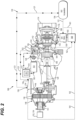
- Fig. 1 a partial view of an embodiment of a system in accordance with the disclosure is shown in Fig. 1 and is designated generally by reference character 100.
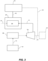
- Fig. 2 Other embodiments and/or aspects of this disclosure are shown in Fig. 2 .
- the systems and methods described herein can be used to improve engine efficiency, reduce carbon emissions, and improve power to weight ratio.
- the primary gas path 106 includes, in fluid series communication: an air inlet 112, the compressor 104 fluidly connected to the air inlet 112, the combustor 108 fluidly connected to an outlet 114 of the compressor 104, and a turbine section 116 fluidly connected to an outlet 118 of the combustor 108, the turbine section 116 operatively connected to the compressor 104 to drive the compressor 104.
- a main output shaft 120 is operatively connected to the turbine section 116 to be driven by the turbine section 116.
- a heat exchanger 122 is fluidly connected between a liquid hydrogen supply 124 and the compressor 104.
- a gas conduit 126 is fluidly connected to the primary gas path 106, and a fluid conduit 128, carrying liquid hydrogen from the liquid hydrogen supply 124, in thermal communication with the gas conduit 126, but is fluidly isolated from the gas conduit 126, fluidly connects the liquid hydrogen supply 124 to the primary gas path 106.
- the compressor 104 includes a first stage (e.g. low pressure) compressor 140 and a second stage (e.g. high pressure) compressor 142.
- the second stage compressor 142 is in fluid communication with the first stage compressor 140 through an inter-stage duct 144.
- the heat exchanger 122 is fluidly connected to the primary gas path 106 between the adjacent first and second stage compressors 140, 142 such that the inter-stage duct 144 forms a compressor air conduit through the heat exchanger 122.
- hot compressed air from the first stage compressor 140 passes through conduit 126 to the second stage compressor 142, where heat is exchanged in the heat exchanger 122 so that liquid hydrogen in the fluid conduit 128 is evaporated to gaseous hydrogen.
- the expansion turbine 134 is operatively connected to the main shaft 120 (e.g. via the gearbox 148 and output shaft 151) to drive the main shaft 120 in parallel with the turbine section 116. In this manner, the main shaft 120 is driven by combined power from the turbine section 116 and the expansion turbine 134.
- the hydrogen expansion turbine 134 can be operatively connected to one or both of an electrical power generator 152 to drive the electrical power generator 152, and an auxiliary air compressor 154 to drive the auxiliary air compressor 154.
- a gaseous hydrogen accumulator 156 is disposed in conduit 139 downstream of the heat exchanger 122 relative to hydrogen flow, wherein the gaseous hydrogen accumulator 156 is between the heat exchanger 122 and the combustor 108.
- a gaseous hydrogen meter 158 is disposed in the conduit 139 downstream of the gaseous hydrogen accumulator 156 relative to hydrogen flow for controlling flow of hydrogen to the combustor 108, the gaseous hydrogen meter 158 being between the accumulator 156 and the combustor 108.
- the expanded low pressure gaseous hydrogen 121 is collected and stored in the gaseous hydrogen accumulator 156 and then regulated to a pressure where it can then be metered (e.g. via meter 158) to provide combustor ready hydrogen gas to the combustor 108.
- a controller 160 is operatively connected to the gaseous hydrogen meter 158 and at least one sensor included in any of the gearbox 148, the hydrogen expansion turbine 134, and/or the turbine section 116.
- the controller 160 can include machine readable instructions that cause the controller to receive input 145 for a command power, receive input 147 from at least one of the gearbox 148, the hydrogen expansion turbine 134, and/or the turbine section 136, and adjust the flow of gaseous hydrogen 121 via the gaseous hydrogen meter 158 to achieve the command power, based on the input (e.g. signals 161, 162, 163, 164) received by the controller 160.
- the controller 160 can additionally receive input from a compressor pressure (e.g. P3 pressure, upstream of the accumulator 156) and input from the accumulator 156 downstream of the compressor pressure.
- the controller 160 can include machine readable instruction operable to execute the method.
- the method includes, supplying liquid hydrogen 119 to a heat exchanger 122 and expanding the liquid hydrogen 119 to gaseous hydrogen 121 with heat supplied to the heat exchanger 122, supplying the heat to the heat exchanger 122 with compressed air from a first stage compressor 140, where expanding the liquid hydrogen 119 to gaseous hydrogen 121 includes cooling the compressed air from the first stage compressor 140, compressing cooled air from the heat exchanger 122, and combusting the gaseous hydrogen 121 with the compressed cooled air in the combustor 108.
- the method includes extracting power from a flow of gaseous hydrogen 121 with a hydrogen expansion turbine 134 downstream of the heat exchanger 122. In certain embodiments, the method includes combining power from the expansion turbine 134 with power from a main shaft 120 driven by a turbine section 116 to drive an output shaft 151 for example to generate thrust and/or electrical power. In certain embodiments, the method includes receiving input from at least one of the gearbox 148, the hydrogen expansion turbine 134, and/or the turbine section 116 (e.g. signals 161, 162, 163, 164) and outputting a command 165 to the gaseous hydrogen meter 158 to adjust flow of gaseous hydrogen 121 to the combustor 108 to achieve a command power output at the output shaft 151.
- the gearbox 148 the hydrogen expansion turbine 134
- the turbine section 116 e.g. signals 161, 162, 163, 164
- a dual cycle intercooled architecture as described herein can be retrofit on an existing, conventional gas turbine engine.
- any or all of a liquid hydrogen supply 124, heat exchanger 122, a gaseous hydrogen accumulator 156, a gaseous hydrogen meter 158, an expansion turbine 134 between the heat exchanger 122 and the gaseous hydrogen accumulator 156 can be introduced in an existing turbine engine.
- the system can then be connected as follows: connecting the liquid hydrogen supply 124 to the heat exchanger 122 via a liquid hydrogen pump 133 in a first line (e.g. fluid conduit 128), connecting the heat exchanger 122 to the expansion turbine 134 via a second line (e.g.
- conduit 139 an upstream portion of conduit 139
- conduit 139 connecting the expansion turbine 134 to the combustor via a third line (e.g. a downstream portion of conduit 139), wherein the gaseous hydrogen accumulator 156 and gaseous hydrogen meter 158 are disposed in the third line.
- the liquid hydrogen tank 131 is fluidly connected to the liquid hydrogen supply 124 for supplying hydrogen to a hydrogen conversion module 266.
- the hydrogen conversion module 266 can be included within the engine 200, for combustion of hydrogen within the combustor 108.
- the hydrogen conversion module 266 is fluidly connected to the inlet 136 of the expansion turbine 134 for driving the expansion turbine 134.
- the hydrogen conversion module 266 can includes all of heat exchanger 122, liquid H2 pump 133, accumulator 156, and a meter 158.
- the hydrogen conversion module 266 can be any suitable different combination of elements interconnected to be operable to provide a supply of gaseous hydrogen, for example a combination that is suitable to the particular engine with which the hydrogen conversion module 266 is used.
- a hydrogen combustion module 268 can be fluidly connected to the outlet 138 of the expansion turbine 134 and operatively connected to the output shaft 151, for converting thermal energy into rotational energy to drive the output shaft 151.
- the engine 200 is operatively connected to a driven component 270 via the output shaft 151.
- the driven component 270 is driven by the output shaft 151 of the engine 200 and can be a rotor, for example, or any one of, or any combination of a propeller, a fan, a compressor, a gearbox, an electric generator, or the like.
- the expansion turbine 134 can optionally be operatively connected to another driven component 272 for driving the driven component 272 in series with driven component 270 via shaft 274.
- the driven component 272 can be the same or different than driven component 270. It is also contemplated that the driven component 270 can be optionally operatively connected to driven component 272 via shaft 276 for driving driven component 272 in parallel with driven component 270.
- This architecture differs from other intercooled or expansion turbine engines in that it combines several engine improvements by making use of cold liquid hydrogen for cooling and expansion.
- the methods and systems of the present disclosure as described above and shown in the drawings, provide for improved engine efficiency through intercooling. Additionally, inclusion of the expansion turbine allows for a smaller engine without sacrificing power output, therefore improving power to weight ratio. Carbon emissions may also be reduced or eliminated. Finally, this arrangement accomplishes these improvements in a compact package which would fit in existing nacelle loft lines (e.g. for a turboprop) therefore minimizing drag.
Landscapes
- Engineering & Computer Science (AREA)
- Chemical & Material Sciences (AREA)
- Combustion & Propulsion (AREA)
- Mechanical Engineering (AREA)
- General Engineering & Computer Science (AREA)
- Engine Equipment That Uses Special Cycles (AREA)
- Heat-Exchange Devices With Radiators And Conduit Assemblies (AREA)
Claims (10)
- Gasturbinentriebwerk (100), umfassend:einen primären Gaspfad (106), der in serieller Fluidverbindung Folgendes aufweist: einen Lufteinlass (112), einen Verdichter (104), der mit dem Lufteinlass (112) fluidverbunden ist, eine Brennkammer (108), die mit einem Auslass des Verdichters (104) fluidverbunden ist, und einen Turbinenabschnitt (116), die mit einem Auslass des Brennkammerabschnitts (108) fluidverbunden ist, wobei der Turbinenabschnitt (116) mit dem Verdichter (104) wirkverbunden ist, um den Verdichter (104) anzutreiben;eine Abtriebswelle (151), die mit dem Turbinenabschnitt (116) wirkverbunden ist, um durch den Turbinenabschnitt (116) angetrieben zu werden;einen Wärmetauscher (122), der Folgendes aufweist:eine Gasleitung (126), die mit dem primären Gaspfad (106) fluidverbunden ist; undeine Fluidleitung (128) fluidisoliert von der Gasleitung (126) und in thermischer Verbindung mit der Gasleitung (126), wobei die Fluidleitung (128) einen Einlass (130) für flüssigen Wasserstoff und einen Auslass (132) für gasförmigen Wasserstoff aufweist, der mit dem Einlass (130) für flüssigen Wasserstoff fluidverbunden ist; undeine Expansionsturbine (134), die einen Gaseinlass (136), der mit dem Auslass (132) für gasförmigen Wasserstoff fluidverbunden ist, und einen Gasauslass (138), der mit dem Gaseinlass (136) fluidverbunden ist, aufweist, wobei der Gasauslass (138) der Expansionsturbine (134) mit der Brennkammer (108) fluidverbunden ist, dadurch gekennzeichnet, dass:der Verdichter (104) mehrere Verdichterabschnitte aufweist und die Gasleitung (126) des Wärmetauschers (122) an einer Stelle zwischen benachbarten Verdichterabschnitten der mehreren Verdichterabschnitte mit dem primären Gaspfad (106) fluidverbunden ist; unddas Gasturbinentriebwerk (100) ferner Folgendes umfasst:einen Speicher (156) für gasförmigen Wasserstoff stromabwärts des Wärmetauschers (122) relativ zu dem Wasserstoffstrom, wobei sich der Speicher (156) für gasförmigen Wasserstoff zwischen dem Wärmetauscher (122) und der Brennkammer (108) befindet; undein Messgerät (158) für gasförmigen Wasserstoff stromabwärts des Speichers (156) für gasförmigen Wasserstoff relativ zu dem Wasserstoffstrom zum Steuern des Stroms von Wasserstoff zu der Brennkammer (108), wobei sich das Messgerät (158) für gasförmigen Wasserstoff zwischen dem Speicher (156) und der Brennkammer (108) befindet, wobei die Expansionsturbine (134) eine Wasserstoffexpansionsturbine (134) stromabwärts des Wärmetauschers (122) und stromaufwärts der Brennkammer (108) relativ zu dem Wasserstoffstrom ist und wobei eine Turbinenwelle (146) der Wasserstoffexpansionsturbine (134) mit einem Getriebe (148) wirkverbunden ist.
- Gasturbinentriebwerk (100) nach Anspruch 1, ferner umfassend eine Pumpe (133) für flüssigen Wasserstoff, die mit dem Einlass (130) für flüssigen Wasserstoff des Wärmetauschers (122) fluidverbunden ist und dazu dient, dem Einlass (130) für flüssigen Wasserstoff des Wärmetauschers (122) flüssigen Wasserstoff (119) zuzuführen.
- Gasturbinentriebwerk (100) nach Anspruch 1 oder 2, wobei die Expansionsturbine (134) mit der Abtriebswelle (151) wirkverbunden ist, um die Abtriebswelle (151) parallel zu dem Turbinenabschnitt (116) anzutreiben.
- Gasturbinentriebwerk (100) nach Anspruch 3, wobei das Getriebe (148) mit einer Hauptwelle (120) wirkverbunden ist, die durch einen Turbinenabschnitt (116) des Gasturbinentriebwerks (100) angetrieben wird, wobei das Getriebe (148) ferner die Abtriebswelle (151) beinhaltet, die durch kombinierte Leistung von dem Turbinenabschnitt (116) und der Expansionsturbine (134) angetrieben wird.
- Gasturbinentriebwerk (100) nach einem der vorhergehenden Ansprüche, wobei die Expansionsturbine (134) mit einem Stromgenerator (152) wirkverbunden ist, um den Stromgenerator (152) anzutreiben.
- Gasturbinentriebwerk (100) nach einem der vorhergehenden Ansprüche, wobei die Expansionsturbine (134) mit einem Hilfs-Luftverdichter (154) wirkverbunden ist, um den Hilfs-Luftverdichter (154) anzutreiben.
- Gasturbinentriebwerk (100) nach einem der vorhergehenden Ansprüche, wobei ein Auslass der Wasserstoffexpansionsturbine (134) in Fluidverbindung mit der Brennkammer (108) steht, um der Brennkammer (108) brennkammerbereites Wasserstoffgas bereitzustellen und um dem Getriebe (148) zusätzliche Rotationsleistung zuzugeben, wobei das Getriebe (148) mit einer Hauptwelle (120) wirkverbunden ist, die durch den Turbinenabschnitt (116) des Gasturbinentriebwerks (100) angetrieben wird, und wobei das Getriebe (148) ferner die Abtriebswelle (151) beinhaltet, die durch kombinierte Leistung von dem Turbinenabschnitt (116) und der Expansionsturbine (134) angetrieben wird.
- Gasturbinentriebwerk (100) nach Anspruch 7, ferner umfassend eine Steuerung (160), die mit dem Messgerät (158) für gasförmigen Wasserstoff und mindestens einem Sensor in dem Getriebe (148), der Wasserstoffexpansionsturbine (134) und/oder dem Turbinenabschnitt (116) wirkverbunden ist, wobei die Steuerung (160) maschinenlesbare Anweisungen beinhaltet, die die Steuerung (160) zu Folgendem veranlassen:Empfangen einer Eingabe (145) für einen Befehl (165) Leistung;Empfangen einer Eingabe (147) von dem Getriebe (148), der Wasserstoffexpansionsturbine (134) und/oder dem Turbinenabschnitt (116); undEinstellen des Stroms des gasförmigen Wasserstoffs (121) über das Messgerät (158) für gasförmigen Wasserstoff, um die Befehlsleistung zu erreichen.
- Verfahren zum Nachrüsten eines Gasturbinentriebwerks (100) mit einer Doppelzyklus-Zwischenkühlungsarchitektur, wobei das Verfahren Folgendes umfasst:Einführen einer Versorgung (124) für flüssigen Wasserstoff;Einführen eines Wärmetauschers (122) in einen Kanal zwischen dem Verdichter (140) der ersten Stufe und dem Verdichter (142) der zweiten Stufe;Einführen eines Speichers (156) für gasförmigen Wasserstoff und eines Messgeräts (158) für gasförmigen Wasserstoff zwischen dem Wärmetauscher (122) und dem Verdichter (142) der zweiten Stufe; undEinführen einer Expansionsturbine (134) zwischen dem Wärmetauscher (122) und dem Speicher (156) für gasförmigen Wasserstoff, wobei die Expansionsturbine (134) mit einem Getriebe (148) wirkverbunden ist.
- Verfahren nach Anspruch 9, ferner umfassend:Verbinden der Versorgung (124) für flüssigen Kraftstoff mit dem Wärmetauscher (122) über eine Pumpe (133) für flüssigen Wasserstoff in einer ersten Leitung;Verbinden des Wärmetauschers (122) mit der Expansionsturbine (134) über eine zweite Leitung; undVerbinden der Expansionsturbine (134) mit dem Verdichter (142) der zweiten Stufe über eine dritte Leitung, wobei der Speicher (156) für gasförmigen Wasserstoff und das Messgerät (158) für gasförmigen Wasserstoff in der dritten Leitung angeordnet sind.
Priority Applications (1)
| Application Number | Priority Date | Filing Date | Title |
|---|---|---|---|
| EP25170218.9A EP4600471A1 (de) | 2021-05-27 | 2022-05-27 | Wasserstoffmotor mit doppelzyklus-zwischenkühlungsarchitektur |
Applications Claiming Priority (1)
| Application Number | Priority Date | Filing Date | Title |
|---|---|---|---|
| US17/331,942 US11542869B2 (en) | 2021-05-27 | 2021-05-27 | Dual cycle intercooled hydrogen engine architecture |
Related Child Applications (1)
| Application Number | Title | Priority Date | Filing Date |
|---|---|---|---|
| EP25170218.9A Division EP4600471A1 (de) | 2021-05-27 | 2022-05-27 | Wasserstoffmotor mit doppelzyklus-zwischenkühlungsarchitektur |
Publications (3)
| Publication Number | Publication Date |
|---|---|
| EP4095369A2 EP4095369A2 (de) | 2022-11-30 |
| EP4095369A3 EP4095369A3 (de) | 2023-03-01 |
| EP4095369B1 true EP4095369B1 (de) | 2025-04-16 |
Family
ID=81851082
Family Applications (2)
| Application Number | Title | Priority Date | Filing Date |
|---|---|---|---|
| EP25170218.9A Pending EP4600471A1 (de) | 2021-05-27 | 2022-05-27 | Wasserstoffmotor mit doppelzyklus-zwischenkühlungsarchitektur |
| EP22175943.4A Active EP4095369B1 (de) | 2021-05-27 | 2022-05-27 | Wasserstoffmotor mit doppelzyklus-zwischenkühlungsarchitektur |
Family Applications Before (1)
| Application Number | Title | Priority Date | Filing Date |
|---|---|---|---|
| EP25170218.9A Pending EP4600471A1 (de) | 2021-05-27 | 2022-05-27 | Wasserstoffmotor mit doppelzyklus-zwischenkühlungsarchitektur |
Country Status (6)
| Country | Link |
|---|---|
| US (3) | US11542869B2 (de) |
| EP (2) | EP4600471A1 (de) |
| CN (1) | CN115405424A (de) |
| BR (1) | BR102022010304A2 (de) |
| CA (1) | CA3160735A1 (de) |
| PL (1) | PL4095369T3 (de) |
Families Citing this family (11)
| Publication number | Priority date | Publication date | Assignee | Title |
|---|---|---|---|---|
| US11542869B2 (en) * | 2021-05-27 | 2023-01-03 | Pratt & Whitney Canada Corp. | Dual cycle intercooled hydrogen engine architecture |
| US12351337B2 (en) | 2021-11-19 | 2025-07-08 | General Electric Company | Sub-coolers for refueling onboard cryogenic fuel tanks and methods for operating the same |
| US11946419B2 (en) * | 2022-02-23 | 2024-04-02 | General Electric Company | Methods and apparatus to produce hydrogen gas turbine propulsion |
| US20230399986A1 (en) * | 2022-06-09 | 2023-12-14 | General Electric Company | Monitoring systems for hydrogen fueled aircraft |
| US11862781B1 (en) * | 2022-08-15 | 2024-01-02 | Hamilton Sundstrand Corporation | Auxiliary power generation and cooling systems on liquid hydrogen fueled aircraft |
| US11905884B1 (en) * | 2022-09-16 | 2024-02-20 | General Electric Company | Hydrogen fuel system for a gas turbine engine |
| US12209535B2 (en) | 2023-06-16 | 2025-01-28 | Pratt & Whitney Canada Corp. | Turbine engine compressor intercooler |
| US12435664B2 (en) | 2023-06-16 | 2025-10-07 | Pratt & Whitney Canada Corp. | Gas turbine engine with water recovery system |
| US12486803B2 (en) | 2023-06-16 | 2025-12-02 | Pratt & Whitney Canada Corp. | Gas turbine engine system with fuel driven turbine |
| GB202317415D0 (en) * | 2023-11-14 | 2023-12-27 | Rolls Royce Plc | Propulsion system comprising a hydrogen-burning gas turbine engine |
| GB202317413D0 (en) * | 2023-11-14 | 2023-12-27 | Rolls Royce Plc | Propulsion system comprising a hydrogen-burning gas turbine engine |
Family Cites Families (25)
| Publication number | Priority date | Publication date | Assignee | Title |
|---|---|---|---|---|
| CH391375A (de) | 1962-02-26 | 1965-04-30 | Sulzer Ag | Verfahren zum Betrieb einer Kolbenbrennkraftmaschine mit gasförmigem Brennstoff und Kolbenbrennkraftmaschine zur Ausübung des Verfahrens |
| DE2413507A1 (de) * | 1974-03-20 | 1975-10-02 | Motoren Turbinen Union | Gasturbine fuer kryogenen kraftstoff |
| JPH02289135A (ja) | 1989-04-25 | 1990-11-29 | Howa Mach Ltd | 紡機の清掃装置 |
| US5154051A (en) * | 1990-10-22 | 1992-10-13 | General Dynamics Corporation | Air liquefier and separator of air constituents for a liquid air engine |
| US5347806A (en) | 1993-04-23 | 1994-09-20 | Cascaded Advanced Turbine Limited Partnership | Cascaded advanced high efficiency multi-shaft reheat turbine with intercooling and recuperation |
| US6405522B1 (en) * | 1999-12-01 | 2002-06-18 | Capstone Turbine Corporation | System and method for modular control of a multi-fuel low emissions turbogenerator |
| US7246482B2 (en) * | 2004-07-16 | 2007-07-24 | Honeywell International, Inc. | Gas turbine engine bleed air power assist system and method |
| US8146370B2 (en) * | 2008-05-21 | 2012-04-03 | Honeywell International Inc. | Turbine drive system with lock-up clutch and method |
| US8291715B2 (en) * | 2008-06-11 | 2012-10-23 | Honeywell International Inc. | Bi-modal turbine assembly and starter / drive turbine system employing the same |
| US8572974B2 (en) * | 2009-07-31 | 2013-11-05 | Hamilton Sundstrand Corporation | Variable speed and displacement electric fluid delivery system for a gas turbine engine |
| US8984856B2 (en) * | 2010-04-12 | 2015-03-24 | Hamilton Sundstrand Corporation | Flexible fuel system |
| US9249723B2 (en) | 2014-06-13 | 2016-02-02 | Bechtel Power Corporation | Turbo-compound reheat combined cycle power generation |
| GB2531775B (en) * | 2014-10-30 | 2018-05-09 | Rolls Royce Plc | A gas turbine using cryogenic fuel passed through a fuel turbine |
| EP3301278A1 (de) | 2016-09-30 | 2018-04-04 | Siemens Aktiengesellschaft | Gasturbinenanordnung mit geregelter zapflufteinspritzung in die brennkammer, und betriebsverfahren |
| US11041439B2 (en) * | 2018-09-14 | 2021-06-22 | Raytheon Technologies Corporation | Hybrid expander cycle with turbo-generator and cooled power electronics |
| US10989117B2 (en) * | 2018-09-14 | 2021-04-27 | Raytheon Technologies Corporation | Hybrid expander cycle with pre-compression cooling and turbo-generator |
| US11047307B2 (en) * | 2018-09-14 | 2021-06-29 | Raytheon Technologies Corporation | Hybrid expander cycle with intercooling and turbo-generator |
| US10704461B2 (en) * | 2018-09-27 | 2020-07-07 | Garrett Transportation I Inc. | Turbocharged internal combustion engine with a portion of exhaust gases from engine bypassing turbocharger turbine for rapid catalyst light-off without waste gate performance penalty in turbine |
| GB2594893B (en) | 2019-03-21 | 2022-05-18 | Intelligent Energy Ltd | Evaporatively cooled fuel cell systems with cathode exhaust turbine boost |
| US20210340908A1 (en) * | 2020-05-01 | 2021-11-04 | Raytheon Technologies Corporation | Gas turbine engines having cryogenic fuel systems |
| US11448133B2 (en) * | 2020-05-05 | 2022-09-20 | Raytheon Technologies Corporation | Moderate pressure liquid hydrogen storage for hybrid-electric propulsion system |
| EP3978736B1 (de) * | 2020-09-30 | 2025-03-05 | Rolls-Royce plc | Brennstoffzufuhr |
| US11542869B2 (en) * | 2021-05-27 | 2023-01-03 | Pratt & Whitney Canada Corp. | Dual cycle intercooled hydrogen engine architecture |
| GB202114829D0 (en) * | 2021-10-18 | 2021-12-01 | Rolls Royce Plc | Aircraft propulsion system |
| US11692491B1 (en) * | 2022-05-05 | 2023-07-04 | Raytheon Technologies Corporation | Transmission and method for control of boost spool |
-
2021
- 2021-05-27 US US17/331,942 patent/US11542869B2/en active Active
-
2022
- 2022-05-26 BR BR102022010304-6A patent/BR102022010304A2/pt unknown
- 2022-05-26 CA CA3160735A patent/CA3160735A1/en active Pending
- 2022-05-27 CN CN202210586794.9A patent/CN115405424A/zh active Pending
- 2022-05-27 PL PL22175943.4T patent/PL4095369T3/pl unknown
- 2022-05-27 EP EP25170218.9A patent/EP4600471A1/de active Pending
- 2022-05-27 EP EP22175943.4A patent/EP4095369B1/de active Active
- 2022-12-28 US US18/090,152 patent/US12037946B2/en active Active
-
2024
- 2024-06-06 US US18/735,712 patent/US12421899B2/en active Active
Also Published As
| Publication number | Publication date |
|---|---|
| PL4095369T3 (pl) | 2025-06-23 |
| EP4600471A1 (de) | 2025-08-13 |
| US11542869B2 (en) | 2023-01-03 |
| EP4095369A2 (de) | 2022-11-30 |
| US12421899B2 (en) | 2025-09-23 |
| US20220381183A1 (en) | 2022-12-01 |
| CN115405424A (zh) | 2022-11-29 |
| CA3160735A1 (en) | 2022-11-27 |
| US12037946B2 (en) | 2024-07-16 |
| EP4095369A3 (de) | 2023-03-01 |
| BR102022010304A2 (pt) | 2022-12-06 |
| US20230133397A1 (en) | 2023-05-04 |
| US20240328355A1 (en) | 2024-10-03 |
Similar Documents
| Publication | Publication Date | Title |
|---|---|---|
| EP4095369B1 (de) | Wasserstoffmotor mit doppelzyklus-zwischenkühlungsarchitektur | |
| EP3623603B1 (de) | Hybridexpanderzyklus mit turbogenerator und gekühlter leistungselektronik | |
| EP3623602B1 (de) | Hybrider expansionszyklus mit zwischenkühlung und turbogenerator | |
| EP3623604B1 (de) | Hybrider expansionszyklus mit vorverdichtungskühlung und turbogenerator | |
| US20230258130A1 (en) | Turbine engine with mass rejection | |
| EP4123146B1 (de) | Zweitakt-motor mit zwischenkühlungsarchitekturen | |
| US9422863B2 (en) | Method and architecture for recombining the power of a turbomachine | |
| US20240052792A1 (en) | Inter-cooled preheat of steam injected turbine engine | |
| US12270341B2 (en) | Gas turbine engine fuel system | |
| US12078104B2 (en) | Hydrogen steam injected and inter-cooled turbine engine | |
| EP4303416A1 (de) | Turboexpander für turbinenmotoren mit wasserstoffbrennstoffsystemen | |
| RU2376483C1 (ru) | Атомный газотурбинный двигатель с форсажем | |
| EP4279721A1 (de) | Wasserstoffdampfeinspritzturbinenmotor mit rückströmung | |
| EP4279719A1 (de) | Wasserstoffdampfeinspritzturbinenmotor mit gekühlter kühlluft | |
| RU2379532C1 (ru) | Атомный газотурбинный авиационный двигатель | |
| US12104535B2 (en) | Thermal management system for a gas turbine engine | |
| US20250224112A1 (en) | Hydrogen fuelled gas turbine engine | |
| RU2375219C1 (ru) | Атомный газотурбовоз и двигательная установка атомного газотурбовоза | |
| RU2349775C1 (ru) | Атомный газотурбинный авиационный двигатель | |
| RU2336429C1 (ru) | Атомный газотурбинный двигатель |
Legal Events
| Date | Code | Title | Description |
|---|---|---|---|
| PUAI | Public reference made under article 153(3) epc to a published international application that has entered the european phase |
Free format text: ORIGINAL CODE: 0009012 |
|
| STAA | Information on the status of an ep patent application or granted ep patent |
Free format text: STATUS: THE APPLICATION HAS BEEN PUBLISHED |
|
| AK | Designated contracting states |
Kind code of ref document: A2 Designated state(s): AL AT BE BG CH CY CZ DE DK EE ES FI FR GB GR HR HU IE IS IT LI LT LU LV MC MK MT NL NO PL PT RO RS SE SI SK SM TR |
|
| PUAL | Search report despatched |
Free format text: ORIGINAL CODE: 0009013 |
|
| AK | Designated contracting states |
Kind code of ref document: A3 Designated state(s): AL AT BE BG CH CY CZ DE DK EE ES FI FR GB GR HR HU IE IS IT LI LT LU LV MC MK MT NL NO PL PT RO RS SE SI SK SM TR |
|
| RIC1 | Information provided on ipc code assigned before grant |
Ipc: F02C 7/224 20060101ALI20230126BHEP Ipc: F02C 7/16 20060101ALI20230126BHEP Ipc: F02C 3/22 20060101AFI20230126BHEP |
|
| STAA | Information on the status of an ep patent application or granted ep patent |
Free format text: STATUS: REQUEST FOR EXAMINATION WAS MADE |
|
| 17P | Request for examination filed |
Effective date: 20230901 |
|
| RBV | Designated contracting states (corrected) |
Designated state(s): AL AT BE BG CH CY CZ DE DK EE ES FI FR GB GR HR HU IE IS IT LI LT LU LV MC MK MT NL NO PL PT RO RS SE SI SK SM TR |
|
| GRAP | Despatch of communication of intention to grant a patent |
Free format text: ORIGINAL CODE: EPIDOSNIGR1 |
|
| STAA | Information on the status of an ep patent application or granted ep patent |
Free format text: STATUS: GRANT OF PATENT IS INTENDED |
|
| INTG | Intention to grant announced |
Effective date: 20240701 |
|
| GRAJ | Information related to disapproval of communication of intention to grant by the applicant or resumption of examination proceedings by the epo deleted |
Free format text: ORIGINAL CODE: EPIDOSDIGR1 |
|
| STAA | Information on the status of an ep patent application or granted ep patent |
Free format text: STATUS: REQUEST FOR EXAMINATION WAS MADE |
|
| GRAP | Despatch of communication of intention to grant a patent |
Free format text: ORIGINAL CODE: EPIDOSNIGR1 |
|
| STAA | Information on the status of an ep patent application or granted ep patent |
Free format text: STATUS: GRANT OF PATENT IS INTENDED |
|
| INTC | Intention to grant announced (deleted) | ||
| INTG | Intention to grant announced |
Effective date: 20241114 |
|
| GRAS | Grant fee paid |
Free format text: ORIGINAL CODE: EPIDOSNIGR3 |
|
| GRAA | (expected) grant |
Free format text: ORIGINAL CODE: 0009210 |
|
| STAA | Information on the status of an ep patent application or granted ep patent |
Free format text: STATUS: THE PATENT HAS BEEN GRANTED |
|
| AK | Designated contracting states |
Kind code of ref document: B1 Designated state(s): AL AT BE BG CH CY CZ DE DK EE ES FI FR GB GR HR HU IE IS IT LI LT LU LV MC MK MT NL NO PL PT RO RS SE SI SK SM TR |
|
| REG | Reference to a national code |
Ref country code: GB Ref legal event code: FG4D |
|
| REG | Reference to a national code |
Ref country code: CH Ref legal event code: EP Ref country code: DE Ref legal event code: R096 Ref document number: 602022013119 Country of ref document: DE |
|
| REG | Reference to a national code |
Ref country code: IE Ref legal event code: FG4D |
|
| PGFP | Annual fee paid to national office [announced via postgrant information from national office to epo] |
Ref country code: PL Payment date: 20250522 Year of fee payment: 4 Ref country code: DE Payment date: 20250423 Year of fee payment: 4 |
|
| PGFP | Annual fee paid to national office [announced via postgrant information from national office to epo] |
Ref country code: FR Payment date: 20250520 Year of fee payment: 4 |
|
| PGFP | Annual fee paid to national office [announced via postgrant information from national office to epo] |
Ref country code: AT Payment date: 20250721 Year of fee payment: 4 |
|
| PGFP | Annual fee paid to national office [announced via postgrant information from national office to epo] |
Ref country code: CZ Payment date: 20250505 Year of fee payment: 4 |
|
| REG | Reference to a national code |
Ref country code: NL Ref legal event code: MP Effective date: 20250416 |
|
| PG25 | Lapsed in a contracting state [announced via postgrant information from national office to epo] |
Ref country code: NL Free format text: LAPSE BECAUSE OF FAILURE TO SUBMIT A TRANSLATION OF THE DESCRIPTION OR TO PAY THE FEE WITHIN THE PRESCRIBED TIME-LIMIT Effective date: 20250416 |
|
| REG | Reference to a national code |
Ref country code: AT Ref legal event code: MK05 Ref document number: 1785836 Country of ref document: AT Kind code of ref document: T Effective date: 20250416 |
|
| PG25 | Lapsed in a contracting state [announced via postgrant information from national office to epo] |
Ref country code: FI Free format text: LAPSE BECAUSE OF FAILURE TO SUBMIT A TRANSLATION OF THE DESCRIPTION OR TO PAY THE FEE WITHIN THE PRESCRIBED TIME-LIMIT Effective date: 20250416 Ref country code: PT Free format text: LAPSE BECAUSE OF FAILURE TO SUBMIT A TRANSLATION OF THE DESCRIPTION OR TO PAY THE FEE WITHIN THE PRESCRIBED TIME-LIMIT Effective date: 20250818 Ref country code: ES Free format text: LAPSE BECAUSE OF FAILURE TO SUBMIT A TRANSLATION OF THE DESCRIPTION OR TO PAY THE FEE WITHIN THE PRESCRIBED TIME-LIMIT Effective date: 20250416 |
|
| REG | Reference to a national code |
Ref country code: LT Ref legal event code: MG9D |
|
| PG25 | Lapsed in a contracting state [announced via postgrant information from national office to epo] |
Ref country code: NO Free format text: LAPSE BECAUSE OF FAILURE TO SUBMIT A TRANSLATION OF THE DESCRIPTION OR TO PAY THE FEE WITHIN THE PRESCRIBED TIME-LIMIT Effective date: 20250716 Ref country code: GR Free format text: LAPSE BECAUSE OF FAILURE TO SUBMIT A TRANSLATION OF THE DESCRIPTION OR TO PAY THE FEE WITHIN THE PRESCRIBED TIME-LIMIT Effective date: 20250717 |
|
| PG25 | Lapsed in a contracting state [announced via postgrant information from national office to epo] |
Ref country code: BG Free format text: LAPSE BECAUSE OF FAILURE TO SUBMIT A TRANSLATION OF THE DESCRIPTION OR TO PAY THE FEE WITHIN THE PRESCRIBED TIME-LIMIT Effective date: 20250416 |
|
| PG25 | Lapsed in a contracting state [announced via postgrant information from national office to epo] |
Ref country code: HR Free format text: LAPSE BECAUSE OF FAILURE TO SUBMIT A TRANSLATION OF THE DESCRIPTION OR TO PAY THE FEE WITHIN THE PRESCRIBED TIME-LIMIT Effective date: 20250416 Ref country code: AT Free format text: LAPSE BECAUSE OF FAILURE TO SUBMIT A TRANSLATION OF THE DESCRIPTION OR TO PAY THE FEE WITHIN THE PRESCRIBED TIME-LIMIT Effective date: 20250416 |
|
| PG25 | Lapsed in a contracting state [announced via postgrant information from national office to epo] |
Ref country code: RS Free format text: LAPSE BECAUSE OF FAILURE TO SUBMIT A TRANSLATION OF THE DESCRIPTION OR TO PAY THE FEE WITHIN THE PRESCRIBED TIME-LIMIT Effective date: 20250716 |
|
| PG25 | Lapsed in a contracting state [announced via postgrant information from national office to epo] |
Ref country code: IS Free format text: LAPSE BECAUSE OF FAILURE TO SUBMIT A TRANSLATION OF THE DESCRIPTION OR TO PAY THE FEE WITHIN THE PRESCRIBED TIME-LIMIT Effective date: 20250816 |
|
| PG25 | Lapsed in a contracting state [announced via postgrant information from national office to epo] |
Ref country code: LV Free format text: LAPSE BECAUSE OF FAILURE TO SUBMIT A TRANSLATION OF THE DESCRIPTION OR TO PAY THE FEE WITHIN THE PRESCRIBED TIME-LIMIT Effective date: 20250416 |