EP4144952B1 - Procédé de forage horizontal et système de forage horizontal - Google Patents
Procédé de forage horizontal et système de forage horizontal Download PDFInfo
- Publication number
- EP4144952B1 EP4144952B1 EP22194255.0A EP22194255A EP4144952B1 EP 4144952 B1 EP4144952 B1 EP 4144952B1 EP 22194255 A EP22194255 A EP 22194255A EP 4144952 B1 EP4144952 B1 EP 4144952B1
- Authority
- EP
- European Patent Office
- Prior art keywords
- drill
- process according
- binder agent
- drilling
- drill string
- Prior art date
- Legal status (The legal status is an assumption and is not a legal conclusion. Google has not performed a legal analysis and makes no representation as to the accuracy of the status listed.)
- Active
Links
Images


Classifications
-
- E—FIXED CONSTRUCTIONS
- E21—EARTH OR ROCK DRILLING; MINING
- E21B—EARTH OR ROCK DRILLING; OBTAINING OIL, GAS, WATER, SOLUBLE OR MELTABLE MATERIALS OR A SLURRY OF MINERALS FROM WELLS
- E21B17/00—Drilling rods or pipes; Flexible drill strings; Kellies; Drill collars; Sucker rods; Cables; Casings; Tubings
- E21B17/02—Couplings; joints
-
- E—FIXED CONSTRUCTIONS
- E21—EARTH OR ROCK DRILLING; MINING
- E21B—EARTH OR ROCK DRILLING; OBTAINING OIL, GAS, WATER, SOLUBLE OR MELTABLE MATERIALS OR A SLURRY OF MINERALS FROM WELLS
- E21B7/00—Special methods or apparatus for drilling
- E21B7/04—Directional drilling
- E21B7/046—Directional drilling horizontal drilling
-
- E—FIXED CONSTRUCTIONS
- E21—EARTH OR ROCK DRILLING; MINING
- E21B—EARTH OR ROCK DRILLING; OBTAINING OIL, GAS, WATER, SOLUBLE OR MELTABLE MATERIALS OR A SLURRY OF MINERALS FROM WELLS
- E21B7/00—Special methods or apparatus for drilling
- E21B7/28—Enlarging drilled holes, e.g. by counterboring
-
- E—FIXED CONSTRUCTIONS
- E21—EARTH OR ROCK DRILLING; MINING
- E21B—EARTH OR ROCK DRILLING; OBTAINING OIL, GAS, WATER, SOLUBLE OR MELTABLE MATERIALS OR A SLURRY OF MINERALS FROM WELLS
- E21B7/00—Special methods or apparatus for drilling
- E21B7/28—Enlarging drilled holes, e.g. by counterboring
- E21B7/30—Enlarging drilled holes, e.g. by counterboring without earth removal
Definitions
- the invention relates to a horizontal drilling method according to the preamble of claim 1 and a horizontal drilling system according to the preamble of claim 14.
- the usual method in civil engineering for creating a borehole for laying underground pipelines with a diameter of up to 1000 mm is the horizontal directional drilling method. Since this method avoids the need to dig a trench, it is particularly suitable for crossing under flowing water, roads and motorways, etc.
- the horizontal directional drilling rig uses a drill head to drill a pilot hole from a starting pit towards the target pit.
- the drill head is screwed to the drill string, which is made up of drill rods screwed together piece by piece, which is driven into the ground by the horizontal directional drilling rig and has a certain degree of flexibility.
- the drill rod diameter is smaller than that of the drill head, leaving an annular space free.
- a bentonite drilling fluid is pumped through the rod to the drill head, where it exits and flushes the drilling cuttings out through the annular space.
- the drilling fluid also ensures that the borehole is supported and seals the borehole wall.
- it serves to cool the drill head and as a lubricant.
- the drill head Once the drill head has reached the target pit, it is replaced with a so-called reamer.
- the reamer has a larger diameter than the drill head and expands the pilot hole when it is pulled back, while simultaneously compacting the borehole walls. Depending on the nature of the soil, more drilling cuttings are removed or more are displaced. Attached to the reamer, either another drill string can be pulled into the borehole for further expansion steps or, finally, one or more pipes can be pulled into the borehole.
- the invention is characterized by the incorporation of at least one jet grouting element (DSE) into the drill rod, with which DSE binder introduced into the drill rod is injected into the soil surrounding the borehole using a jet grouting method before step 3) or during step 1), whereby a binder column is created around the borehole.
- DSE jet grouting element
- the method makes it possible to carry out horizontal drilling in unstable soil, which is not possible with prior art methods. With the known methods, the borehole becomes unstable in such soils or, in the worst case, collapses. Unstable soils which are unsuitable for prior art methods, but into which a stable borehole can be drilled using the present method, contain, for example, Rhine gravel or coarse gravel without a significant fine grain content.
- the method makes it possible to produce an essentially horizontal borehole even in unstable soil, without that the borehole is in danger of settling. Settlements on the surface of the soil are therefore avoided. Since the existing soil is saturated by the binder column, groundwater cannot wash out the soil around the borehole and destabilize it. If the stability of the soil allows it, at least one DSE can be used between the drill head and the drill rod. This allows work steps 1) and 2) to be carried out simultaneously.
- the jet grouting method is a high-pressure injection (HDI) or a low-pressure injection (NDI).
- HDI high-pressure injection
- NDI low-pressure injection
- the jet jet with the HDI at up to 750 bar. If the soil is such that the drill head can cut open the grain structure, it is possible to use the NDI, which uses pressures of only up to 250 bar. This allows the appropriate jet grouting method to be selected depending on the soil condition.
- the binding agent is preferably a cement suspension. This suspension penetrates into the soil and, together with the cut grain structure, forms a stable binding agent column around the borehole.
- a plurality of jet blasting elements are integrated one after the other into the drill rod, and the opening and closing of the nozzles of a DSE is controlled via the first end of the drill rod, which is free from the binding agent supply line.
- An existing drilling system can therefore be supplemented with the special DSE with little effort. These only have to be screwed in between two drill rods. Any existing end of the drill rod can be used to enable the binding agent column to be produced continuously and without interruption. If a DSE fails, for example because a nozzle is blocked, another DSE can be used at any time.
- a coupling element is provided between the second end of the drill rod, at which the binding agent is introduced, and the binding agent supply line from a mixing plant, in which coupling element the drill rod can rotate.
- the coupling element establishes the connection between the rigid binding agent supply line and the rotating drill rod.
- the invention is also preferably characterized in that the drill rod is moved back and forth and rotated over a distance of no more than 7 m during the hardening time of the binder. During the hardening time of the binder column, the drill rod does not stick to the binder and can continue to be turned and rotated after the hardening time.
- removal wings are provided on the coupling ends of the pipe rods, which remove binding agent along the entire length of the borehole during the curing time. This means that the drill rod is gradually “cut free” and remains mobile at all times.
- the borehole is widened with a reamer after step 1) and flushed with bentonite.
- a reamer after step 1) and flushed with bentonite.
- step 3 It is advisable to check and clean the borehole after step 3) or 4). This step is called a "clean run”. This can prevent a product pipe from getting stuck during the pull-in process or can detect other errors in the borehole.
- step 3) or 4 a product pipe is pulled into the borehole using the drill rod. This means that the drilling process is used to lay pipes with all the advantages of the horizontal directional drilling process, but also in unstable soils.
- test pipe it is best to check and clean the borehole by pulling a product pipe of no more than 5 m in length through the borehole. If this test pipe can be pulled completely through the borehole, it can be assumed that the entire product pipe can also be pulled into the borehole. In addition, the test pipe can remove contaminants from the borehole.
- a plurality of boreholes are drilled along a tunnel arch, the binder columns of which touch, the soil inside the tunnel arch is removed, the tunnel arch is reinforced with anchors that penetrate the binding agent columns and the tunnel arch is clad with shotcrete.
- a borehole and a binder column are created, a strand is pulled into the borehole, the strand is tensioned and anchored at both ends and the cavity remaining in the borehole is filled with a filling material. This makes it possible to stop the settlement process of the soil beneath a building with little effort and prevent the building from sinking further.
- a further aspect of the invention relates to a horizontal drilling system for carrying out a horizontal drilling method according to the above description and according to the preamble of claim 14.
- the invention is also characterized in that at least one DSE with at least one nozzle on its casing and preferably several interconnected DSE can be arranged between two adjacent drill rods, one of the drill rods being used to control the closure or opening of the nozzles via the first end of the drill rod and the other drill rod being used to supply the DSE with binding agent via the second end of the drill rod.
- the existing drill rod can be used optimally for operating the HDI or the NDI.
- the failure of a DSE can be immediately compensated by putting another DSE into operation. The time-consuming removal of the drill rod and the replacement of the broken DSE with a functioning DSE can thus be avoided.
- removal wings are formed on the coupling ends of the drill rods, the circumferential circle of which has a larger diameter than the respective coupling end. This allows the drill rod to be cut free by constant rotation while the binder column is hardening.
- the system for supplying binding agent from a mixing plant expediently has a coupling element through which the binding agent is introduced into the second end of the drill rod and in which coupling element the drill rod can rotate in a sealed manner.
- the coupling element can be used to establish a connection between the fixed binding agent supply line and the rotating drill rod.
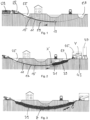
- a borehole is shown, which is designated as a whole with the reference number 11.
- the borehole 11 is created without having to dig a trench, since a horizontal drilling method is used.
- a pilot hole is made.
- a drill head 13 is driven into the ground at the tip of a drill rod 15.
- the drill rod 15 is created by a plurality of drill rods 17 coupled to one another.
- the facing sides of adjacent drill rods 17 can, for example, be screwed into one another.
- one drill rod has an external thread 19 and the other drill rod has an internal thread 21.
- the respective direction of displacement of the drill rod 15 is shown in the figures with an arrow.
- a drilling device 23 sets the drill rod 15 and the drill head 13 in rotation, whereby the drill head is driven from a starting pit 25 towards a target pit 27.
- the drill rod 15 is gradually extended by another drill rod 17 until the drill head 13 reaches the target pit 27.
- bentonite is added to the drill rod 15, which cools and lubricates the drill head 13 and flushes the drilling cuttings out of the borehole.
- the emerging drilling fluid is enriched with drilling cuttings and collects in the starting pit, from where it is pumped back to the mixing plant via the recycling plant.
- discharged drilling cuttings are separated from the bentonite fluid so that the drilling fluid can be reused.
- This first process step is in Figure 1 shown.
- each DSE 31 has at least one nozzle 33 and an external thread 19 or an internal thread 21 at its ends. This allows each DSE 31 to be connected to a drill rod 17 or to another DSE 31.
- the drill rod has a first end 35 and a second end 37.
- a binding agent is introduced into the drill rod 15 and the DSE 31 via the second end 37.
- the binding agent is preferably a cement suspension.
- the nozzles 33 of a DSE 31 mix the binding agent with the existing soil, whereby a binding agent column 39 hardens around the borehole 11 and stabilizes the borehole 11. For reasons of redundancy, several DSE 31s are arranged one behind the other. If the nozzles 33 of a DSE 31 become clogged, another DSE 31 with functioning nozzles 33 can be put into operation.
- the nozzles 33 of a DSE 31 are opened and closed via a valve 41.
- the valve 41 is controlled, for example, via a control line, compressed air, a radio signal, mechanically, or a retraction movement.
- the control line can be implemented via the first end 35 in the drill rod 15.
- the valve 41 can receive compressed air if a flap 42 is opened on the drill rod 17 connected to the DSE 31. If a nozzle 33 becomes clogged in the middle of the borehole 11, the drill rod 15 does not have to be completely pulled out of the borehole, but another DSE 31 can be activated.
- a nozzle 31 has a diameter of 2.5 to 6 mm.
- the DSE 31 are pulled from the target pit 27 into the starting pit 25 ( Figure 2 ).
- the entire borehole is reinforced with a binder column 39. Settlement of the soil and the surface is therefore reliably prevented by the binder column 39.
- the soil where the borehole 11 is located is saturated with the binder and groundwater can no longer penetrate into the soil and warp or wash it away.
- a coupling element 43 is provided, which is shown in detail Y in Figure 11
- the binding agent is provided in a mixing plant 45 with cement from a silo 47 and water as a suspension.
- the coupling element 43 enables the binding agent to be introduced through the fixed feed line 49 from the mixing plant 45 into the rotating drill rod 15 by allowing the drill rod 15 to rotate in the coupling element 43.
- the jet grouting process can be a high-pressure injection (HDI) or a low-pressure injection (NDI).
- HDI high-pressure injection
- NDI low-pressure injection
- the binding agent is injected into the existing soil at up to 550 bar. Due to the high pressure, the jet cuts open the grain structure of the soil and mixes it with the binding agent.
- HDI can be carried out in a 1-, 2- or 3-phase process. The binding agent can therefore be injected alone, or with air or water, or with air and water.
- NDI can also be used. With NDI, a pressure of no more than 200 bar is sufficient and this method is therefore more cost-effective.
- the drill rod 15 Since the binding agent column 39 must harden, the drill rod must remain in the borehole for up to 24 hours. To prevent the drill rod from sticking to the binding agent 39 during this time, the drill rod 15 is constantly rotated and moved back and forth linearly by up to 7 m. Removal wings 51 are formed on the coupling ends 50 of the drill rods 17 (see detail Z shown in Figure 12 ). The removal blades 51 can cut the drill rods 17 free from the binding agent by the rotation of the drill rod 15.
- the now hardened borehole can be widened in one or more stages.
- a reamer 52 is integrated into the drill rod 15 and pulled through the borehole 11. If required, this process can be repeated with further reamers 52 with a larger diameter. This allows boreholes 11 to be created with a borehole diameter of up to 100 cm ( Figure 4 ).
- a control cleaner can be pulled through the borehole 11. It is also conceivable to pull a piece of the product pipe 53 to be laid later, with a length of, for example, 5 m, through the borehole 11. If this piece can be pulled through the borehole, it can be assumed that the product pipe 53 can be pulled into the borehole 11 over the entire length. In Figure 5 the borehole 11 is shown, which is now cleaned and inspected and is ready for the insertion of the product pipe 53.
- the product pipe 53 can be a protective pipe for other pipes, cables or a district heating line. However, it can also be the direct carrier pipe, e.g. of a water or gas line.
- the cavity 55 between the binder column 39 or the borehole 11 and the product pipe 53 is filled with a filling material 54 To do this, as in Figure 7 shown, the filling material 54 is pumped into the cavity 55 by a pump 57.
- FIG 8 an embodiment of the method is shown which can be used in safe geological conditions. Bentonite flushing during drilling of the borehole can be dispensed with and the injection of binding agent after the HDI or NDI can take place during drilling. This means that two work steps can be carried out simultaneously, which makes it possible to save a significant amount of time.
- a plurality of DSE 31 can be coupled directly to the drill head 13 and the drill rod 15 can be coupled to the last DSE 31. The resulting drilling cuttings can be split by the HDI and therefore do not have to be transported out of the borehole.
- the embodiment according to the Figure 9 is used when the soil is extremely dense and saturated.
- a reamer 52 on the drill rod 15 is pulled through the borehole 11 several times and the area around 59 of the borehole 11 is rinsed several times with bentonite. This creates space in the soil or loosens it so that the binding agent can be injected into it.
- FIG. 13 to 15 an application of the horizontal drilling method described above is shown to create a tunnel 60: A plurality of boreholes 11 are drilled and binder columns 39 are created by HDI or NDI to create a tunnel arch 61. After the tunnel arch 61 has been created, the soil within the tunnel arch 61 can be removed ( Figure 14 ). The binder columns 39 can then be reinforced with anchors 63. Finally, the tunnel arch 61 can be clad with a cladding 65, preferably made of shotcrete.
- FIG. 16 A further application of the inventive drilling method is in the Figures 16 to 18 shown to carry out a subsoil stabilization beneath a building 66:
- a strand 67 can be pulled into the borehole with the drill rod 15.
- the strand 67 can be a steel cable with head plates at the ends.
- the strand 67 is tensioned and anchored at its ends outside the borehole 11.
- the remaining cavity in the borehole 11 is filled with a filling material 54.
- the strand 67 can stabilize the subsoil and stop the subsidence.
- the present horizontal drilling method makes it possible to produce stable boreholes 11 without digging trenches, even when the ground is unstable and therefore the horizontal directional drilling method cannot be used.
- the consolidation of the ground is achieved by a binder column 39, which is created by injecting a binder into the ground using a jet grouting method.
Landscapes
- Engineering & Computer Science (AREA)
- Life Sciences & Earth Sciences (AREA)
- Geology (AREA)
- Mining & Mineral Resources (AREA)
- Physics & Mathematics (AREA)
- Environmental & Geological Engineering (AREA)
- Fluid Mechanics (AREA)
- General Life Sciences & Earth Sciences (AREA)
- Geochemistry & Mineralogy (AREA)
- Mechanical Engineering (AREA)
- Piles And Underground Anchors (AREA)
- Consolidation Of Soil By Introduction Of Solidifying Substances Into Soil (AREA)
Claims (16)
- Procédé de forage horizontal présentant les étapes de travail suivantes :1) réalisation d'un perçage pilote pour lequel une tête de forage (13), sur un train de tiges (15) avec une multitude de tiges de forage (17) couplées l'une derrière l'autre, est enfoncée dans le sol d'une fosse de départ (25) vers une fosse d'arrivée (27) et de la bentonite est transportée par le train de tiges (15) vers la tête de forage (13) si bien qu'un trou de forage (11) se forme,3) remplacement de la tête de forage (13) par un alésoir (52) dans la fosse d'arrivée (27) et élargissement du trou de forage (11) en tirant l'alésoir (52) de la fosse d'arrivée (27) vers la fosse de départ (25) et4) répétition optionnelle de l'étape (3) avec d'autres alésoirs pour l'élargissement graduel du trou de forage (11)
caractérisé de plus par2) intégration de plusieurs éléments de buse de jet reliés l'un à l'autre (31) dans le train de tiges (15) avec lesquels un liant introduit dans le train de tiges (15) en plus de la bétonite, en particulier une suspension de ciment, est injecté dans le sol qui entoure le trou de forage (11) avec un procédé de jet avant l'étape (3) ou pendant l'étape (1) si bien qu'une colonne de liant (39) durcie se forme tout autour du trou de forage (11). - Procédé de forage selon la revendication 1, caractérisé en ce que le procédé de jet est une injection à haute pression (HDI) ou une injection à basse pression (NDI).
- Procédé de forage selon l'une des revendications 1 ou 2, caractérisé en ce qu'une multitude d'éléments de buse de jet (31) est intégrée dans le train de tiges (17) et l'ouverture et la fermeture des buse de jets d'un élément de buse de jet est commandée par la première extrémité (35) du train de tiges (15) qui est exempt de conduite d'amenée de liant.
- Procédé de forage selon l'une des revendications précédentes, caractérisé en ce qu'il est prévu un élément de couplage (43) entre la seconde extrémité (37) du train de tiges sur laquelle le liant est introduit et la conduite d'amenée de liant (49) d'une installation de mélange, élément de couplage (43) dans lequel le train de tiges (15) peut tourner, élément de couplage (43) dans lequel le train de tiges (15) peut tourner.
- Procédé de forage selon l'une des revendications précédentes, caractérisé en ce que le train de tiges (15) est déplacé en va-et-vient et en rotation pendant le temps de durcissement du liant sur une distance de 7 m au plus.
- Procédé de forage selon la revendication 5, caractérisé en ce que des ailettes d'enlèvement (51) qui enlèvent le liant sur toute la longueur du trou de forage (11) pendant le temps de durcissement sont prévues sur les extrémités de couplage (50) des tiges de forage (17).
- Procédé de forage selon l'une des revendications précédentes, caractérisé en ce que le trou de forage (11) est élargi avec un alésoir après l'étape 1) et est rincé avec de la bétonite.
- Procédé de forage selon l'une des revendications précédentes, caractérisé en ce que le trou de forage (11) est contrôle et nettoyé après l'étape 3) ou 4).
- Procédé de forage selon l'une des revendications précédentes, caractérisé en ce qu'un tube de produit (53) est enfoncé dans le trou de forage (11) au moyen du train de tiges (15) après l'étape 3) ou 4).
- Procédé de forage selon la revendication 9, caractérisé en ce que le contrôle et le nettoyage du trou de forage (11) est effectué par le fait qu'un tube de produit (53) d'une longueur de 5 m maximum est tiré à travers le trou de forage (11).
- Procédé de forage selon l'une des revendications 9 ou 10, caractérisé en ce qu'un espace creux (55) qui existe entre la colonne de liant et le tube de produit (53) est rempli d'un matériau de remplissage (54).
- Procédé de forage selon l'une des revendications 1 à 8, caractérisé en ce que pour la fabrication d'un tunnel- une multitude de trous de forage (11) est forée le long d'une arche de tunnel (61) dont les colonnes de liant (39) sont en contact mutuel,- la terre à l'intérieur de l'arche de tunnel (61) est enlevée,- l'arche de tunnel (61) est armée d'ancrages (63) qui traversent les colonnes de liant et- l'arche de tunnel (61) est revêtue de béton injecté.
- Procédé de forage selon l'une des revendications 1 à 8, caractérisé en ce que pour la stabilisation d'un terrain à bâtir en dessous d'un objet posé, en particulier d'un bâtiment (66),- un trou de forage (11) est une colonne de liant sont réalisés,- un toron (67) est enfoncé dans le trou de forage (11),- le toron (67) est tendu et fixé à ses deux extrémités et- l'espace creux (55) qui reste dans le trou de forage (11) est rempli de matériau de remplissage (54).
- Système de forage horizontal pour réaliser un procédé de forage horizontal selon l'une des revendications précédentes qui présenteune multitude de tiges de forage (17) qui sont reliées en un train de tiges (15) avec une première et une seconde extrémité (35, 37) et qui sont entraînées par un engin de forage (23) et un élément de buse de jet (31) avec au moins une buse (33) est placé sur son enveloppe entre deux tiges de forage voisines (17),caractérisé en ceque plusieurs éléments de buse de jet reliés l'un à l'autre (31) sont placés l'un derrière l'autre entre deux tiges de forage voisines et qu'il existe une vanne (41) sur chaque élément de buse par jet (31), vanne qui ouvre et ferme les buses d'un élément de buse par jet (31), la vanne (41) étant commandée par l'une des tiges de forage (17) par la première extrémité (35) du train de tiges (15) etque l'élément de buse par jet (31) est alimenté en liant par l'autre tige de forage (17) par la seconde extrémité (37) du train de tiges.
- Système de forage horizontal selon la revendication 14, caractérisé en ce que le système présente, pour l'amenée de liant à partir d'une installation de mélange (45), un élément de couplage (43) par lequel le liant est introduit dans la seconde extrémité (37) du train de tiges (15) et élément de couplage (43) dans lequel le train de tiges peut être en rotation de manière étanche.
- Système de forage horizontal selon la revendication 14 ou 15, caractérisé en ce que des ailettes d'enlèvement (51) sont configurées aux extrémités de couplage (50) des tiges de forage (17), ailettes dont la largeur circonférentielle présente un diamètre supérieur à l'extrémité de couplage respective.
Applications Claiming Priority (1)
| Application Number | Priority Date | Filing Date | Title |
|---|---|---|---|
| CH70251/21A CH718952A1 (de) | 2021-09-07 | 2021-09-07 | Horizontalbohrverfahren und Horizontalbohrsystem. |
Publications (2)
| Publication Number | Publication Date |
|---|---|
| EP4144952A1 EP4144952A1 (fr) | 2023-03-08 |
| EP4144952B1 true EP4144952B1 (fr) | 2024-11-20 |
Family
ID=85128692
Family Applications (1)
| Application Number | Title | Priority Date | Filing Date |
|---|---|---|---|
| EP22194255.0A Active EP4144952B1 (fr) | 2021-09-07 | 2022-09-07 | Procédé de forage horizontal et système de forage horizontal |
Country Status (2)
| Country | Link |
|---|---|
| EP (1) | EP4144952B1 (fr) |
| CH (1) | CH718952A1 (fr) |
Families Citing this family (1)
| Publication number | Priority date | Publication date | Assignee | Title |
|---|---|---|---|---|
| CN116291488A (zh) * | 2023-04-04 | 2023-06-23 | 湖南大学 | 基于双机联动的曲线钻进全方位高压旋喷注浆系统及方法 |
Family Cites Families (4)
| Publication number | Priority date | Publication date | Assignee | Title |
|---|---|---|---|---|
| DE29703655U1 (de) | 1997-02-28 | 1997-12-04 | Welldone Engineering GmbH, 29355 Beedenbostel | Werkzeug für Horizontalbohrungen |
| US5979574A (en) | 1997-05-13 | 1999-11-09 | Ozzie's Pipeline Padder, Inc. | Horizontal boring apparatus and method of using the same |
| US9828805B2 (en) | 2013-04-10 | 2017-11-28 | The Charles Machine Works, Inc. | Reamer with replaceable cutters |
| US10526846B2 (en) | 2014-03-06 | 2020-01-07 | Barbco, Inc. | Material exhaust connection for horizontal bore |
-
2021
- 2021-09-07 CH CH70251/21A patent/CH718952A1/de unknown
-
2022
- 2022-09-07 EP EP22194255.0A patent/EP4144952B1/fr active Active
Also Published As
| Publication number | Publication date |
|---|---|
| EP4144952A1 (fr) | 2023-03-08 |
| CH718952A1 (de) | 2023-03-15 |
Similar Documents
| Publication | Publication Date | Title |
|---|---|---|
| EP0646213B2 (fr) | Procede et outil de pose de collecteurs souterrains de liquides et de gaz | |
| EP3303753B1 (fr) | Système et procédé de pose près de la surface de câbles souterrains ou de conduites souterraines dans le sol | |
| EP2080836B1 (fr) | Procédé destiné à la fixation de sections de sol et dispositif destiné à l'exécution du procédé | |
| DE4329208A1 (de) | Vielseitiges Verfahren und Vorrichtung zum Boden-Verstärken und -Verdichten | |
| EP4144952B1 (fr) | Procédé de forage horizontal et système de forage horizontal | |
| EP2650446B1 (fr) | Procédé de fabrication d'une fondation pour une installation offshore | |
| DE2423163A1 (de) | Verfahren zum errichten einer wand im erdreich | |
| DE2422489C2 (de) | Erdbohrer und Verfahren zum Einsetzen von Pfählen o.dgl. | |
| EP2246482B1 (fr) | Procédé et dispositif d'établissement d'un élément de fondation à friction partiellement réduite | |
| EP1400633A2 (fr) | Tête de forage | |
| DE3839760C1 (en) | Double rotary drilling apparatus for making directionally accurate bores, in particular horizontal bores | |
| DE20306797U1 (de) | Hohlbohrkrone für Kernbohrmaschinen | |
| DE19808478C2 (de) | Verfahren zum grabenlosen Verlegen von Rohren | |
| EP3112580B1 (fr) | Procédé et dispositif pour la formation d'une canalisation souterraine | |
| DE4006320C1 (en) | Straight line tunnel borer - has guide tube to which casing is connected with load-out conveyor | |
| EP0151389A1 (fr) | Méthode et dispositif pour la réalisation d'éléments de construction dans le sol tels que pieux, ancrages injectés, murs souterrains ou similaires | |
| DE2755677A1 (de) | Verfahren und vorrichtung zum herstellen von schlitzen im erdreich | |
| CH693934A5 (de) | Verfahren zum Bohren und Verfuellen von Loechern. | |
| DE19940774C2 (de) | Verfahren und Vorrichtung zum Herstellen von flächenhaften Dichtelementen im Erdboden | |
| DE69103027T3 (de) | Verfahren zur präventiven Konsolidierung des Bodens beim Untertagebau. | |
| DE4413471C1 (de) | Verfahren zur Herstellung von liegenden und/oder geneigten, verfestigten Säulen im Baugrund sowie Vorrichtung zur Durchführung des Verfahrens nebst Anwendung | |
| Kogler | Grouting technology in tunnelling/Injektionstechnik im Tunnelbau | |
| EP3663504B1 (fr) | Procédé de terrassement, dispositif de terrassement et installation de terrassement | |
| DE102021116487B3 (de) | Geotextilummantelte Flüssigbodensäulen | |
| DE102020131395B4 (de) | Verfahren zum Sichern eines Bauwerks |
Legal Events
| Date | Code | Title | Description |
|---|---|---|---|
| PUAI | Public reference made under article 153(3) epc to a published international application that has entered the european phase |
Free format text: ORIGINAL CODE: 0009012 |
|
| STAA | Information on the status of an ep patent application or granted ep patent |
Free format text: STATUS: THE APPLICATION HAS BEEN PUBLISHED |
|
| AK | Designated contracting states |
Kind code of ref document: A1 Designated state(s): AL AT BE BG CH CY CZ DE DK EE ES FI FR GB GR HR HU IE IS IT LI LT LU LV MC MK MT NL NO PL PT RO RS SE SI SK SM TR |
|
| STAA | Information on the status of an ep patent application or granted ep patent |
Free format text: STATUS: REQUEST FOR EXAMINATION WAS MADE |
|
| 17P | Request for examination filed |
Effective date: 20230906 |
|
| RBV | Designated contracting states (corrected) |
Designated state(s): AL AT BE BG CH CY CZ DE DK EE ES FI FR GB GR HR HU IE IS IT LI LT LU LV MC MK MT NL NO PL PT RO RS SE SI SK SM TR |
|
| GRAP | Despatch of communication of intention to grant a patent |
Free format text: ORIGINAL CODE: EPIDOSNIGR1 |
|
| STAA | Information on the status of an ep patent application or granted ep patent |
Free format text: STATUS: GRANT OF PATENT IS INTENDED |
|
| RIC1 | Information provided on ipc code assigned before grant |
Ipc: E21B 17/02 20060101ALI20240604BHEP Ipc: E21B 7/28 20060101ALI20240604BHEP Ipc: E21B 7/30 20060101ALI20240604BHEP Ipc: E21B 7/04 20060101AFI20240604BHEP |
|
| INTG | Intention to grant announced |
Effective date: 20240626 |
|
| GRAS | Grant fee paid |
Free format text: ORIGINAL CODE: EPIDOSNIGR3 |
|
| GRAA | (expected) grant |
Free format text: ORIGINAL CODE: 0009210 |
|
| STAA | Information on the status of an ep patent application or granted ep patent |
Free format text: STATUS: THE PATENT HAS BEEN GRANTED |
|
| AK | Designated contracting states |
Kind code of ref document: B1 Designated state(s): AL AT BE BG CH CY CZ DE DK EE ES FI FR GB GR HR HU IE IS IT LI LT LU LV MC MK MT NL NO PL PT RO RS SE SI SK SM TR |
|
| REG | Reference to a national code |
Ref country code: GB Ref legal event code: FG4D Free format text: NOT ENGLISH |
|
| REG | Reference to a national code |
Ref country code: CH Ref legal event code: EP |
|
| REG | Reference to a national code |
Ref country code: DE Ref legal event code: R096 Ref document number: 502022002168 Country of ref document: DE |
|
| REG | Reference to a national code |
Ref country code: IE Ref legal event code: FG4D Free format text: LANGUAGE OF EP DOCUMENT: GERMAN |
|
| REG | Reference to a national code |
Ref country code: LT Ref legal event code: MG9D |
|
| REG | Reference to a national code |
Ref country code: NL Ref legal event code: MP Effective date: 20241120 |
|
| PG25 | Lapsed in a contracting state [announced via postgrant information from national office to epo] |
Ref country code: PT Free format text: LAPSE BECAUSE OF FAILURE TO SUBMIT A TRANSLATION OF THE DESCRIPTION OR TO PAY THE FEE WITHIN THE PRESCRIBED TIME-LIMIT Effective date: 20250320 Ref country code: HR Free format text: LAPSE BECAUSE OF FAILURE TO SUBMIT A TRANSLATION OF THE DESCRIPTION OR TO PAY THE FEE WITHIN THE PRESCRIBED TIME-LIMIT Effective date: 20241120 Ref country code: IS Free format text: LAPSE BECAUSE OF FAILURE TO SUBMIT A TRANSLATION OF THE DESCRIPTION OR TO PAY THE FEE WITHIN THE PRESCRIBED TIME-LIMIT Effective date: 20250320 |
|
| PG25 | Lapsed in a contracting state [announced via postgrant information from national office to epo] |
Ref country code: FI Free format text: LAPSE BECAUSE OF FAILURE TO SUBMIT A TRANSLATION OF THE DESCRIPTION OR TO PAY THE FEE WITHIN THE PRESCRIBED TIME-LIMIT Effective date: 20241120 Ref country code: NL Free format text: LAPSE BECAUSE OF FAILURE TO SUBMIT A TRANSLATION OF THE DESCRIPTION OR TO PAY THE FEE WITHIN THE PRESCRIBED TIME-LIMIT Effective date: 20241120 |
|
| PG25 | Lapsed in a contracting state [announced via postgrant information from national office to epo] |
Ref country code: BG Free format text: LAPSE BECAUSE OF FAILURE TO SUBMIT A TRANSLATION OF THE DESCRIPTION OR TO PAY THE FEE WITHIN THE PRESCRIBED TIME-LIMIT Effective date: 20241120 |
|
| PG25 | Lapsed in a contracting state [announced via postgrant information from national office to epo] |
Ref country code: ES Free format text: LAPSE BECAUSE OF FAILURE TO SUBMIT A TRANSLATION OF THE DESCRIPTION OR TO PAY THE FEE WITHIN THE PRESCRIBED TIME-LIMIT Effective date: 20241120 |
|
| PG25 | Lapsed in a contracting state [announced via postgrant information from national office to epo] |
Ref country code: NO Free format text: LAPSE BECAUSE OF FAILURE TO SUBMIT A TRANSLATION OF THE DESCRIPTION OR TO PAY THE FEE WITHIN THE PRESCRIBED TIME-LIMIT Effective date: 20250220 |
|
| PG25 | Lapsed in a contracting state [announced via postgrant information from national office to epo] |
Ref country code: LV Free format text: LAPSE BECAUSE OF FAILURE TO SUBMIT A TRANSLATION OF THE DESCRIPTION OR TO PAY THE FEE WITHIN THE PRESCRIBED TIME-LIMIT Effective date: 20241120 Ref country code: GR Free format text: LAPSE BECAUSE OF FAILURE TO SUBMIT A TRANSLATION OF THE DESCRIPTION OR TO PAY THE FEE WITHIN THE PRESCRIBED TIME-LIMIT Effective date: 20250221 |
|
| PG25 | Lapsed in a contracting state [announced via postgrant information from national office to epo] |
Ref country code: PL Free format text: LAPSE BECAUSE OF FAILURE TO SUBMIT A TRANSLATION OF THE DESCRIPTION OR TO PAY THE FEE WITHIN THE PRESCRIBED TIME-LIMIT Effective date: 20241120 |
|
| PG25 | Lapsed in a contracting state [announced via postgrant information from national office to epo] |
Ref country code: RS Free format text: LAPSE BECAUSE OF FAILURE TO SUBMIT A TRANSLATION OF THE DESCRIPTION OR TO PAY THE FEE WITHIN THE PRESCRIBED TIME-LIMIT Effective date: 20250220 |
|
| PG25 | Lapsed in a contracting state [announced via postgrant information from national office to epo] |
Ref country code: SM Free format text: LAPSE BECAUSE OF FAILURE TO SUBMIT A TRANSLATION OF THE DESCRIPTION OR TO PAY THE FEE WITHIN THE PRESCRIBED TIME-LIMIT Effective date: 20241120 |
|
| PG25 | Lapsed in a contracting state [announced via postgrant information from national office to epo] |
Ref country code: DK Free format text: LAPSE BECAUSE OF FAILURE TO SUBMIT A TRANSLATION OF THE DESCRIPTION OR TO PAY THE FEE WITHIN THE PRESCRIBED TIME-LIMIT Effective date: 20241120 |
|
| PG25 | Lapsed in a contracting state [announced via postgrant information from national office to epo] |
Ref country code: EE Free format text: LAPSE BECAUSE OF FAILURE TO SUBMIT A TRANSLATION OF THE DESCRIPTION OR TO PAY THE FEE WITHIN THE PRESCRIBED TIME-LIMIT Effective date: 20241120 |
|
| PG25 | Lapsed in a contracting state [announced via postgrant information from national office to epo] |
Ref country code: RO Free format text: LAPSE BECAUSE OF FAILURE TO SUBMIT A TRANSLATION OF THE DESCRIPTION OR TO PAY THE FEE WITHIN THE PRESCRIBED TIME-LIMIT Effective date: 20241120 |
|
| PG25 | Lapsed in a contracting state [announced via postgrant information from national office to epo] |
Ref country code: SK Free format text: LAPSE BECAUSE OF FAILURE TO SUBMIT A TRANSLATION OF THE DESCRIPTION OR TO PAY THE FEE WITHIN THE PRESCRIBED TIME-LIMIT Effective date: 20241120 |
|
| PG25 | Lapsed in a contracting state [announced via postgrant information from national office to epo] |
Ref country code: CZ Free format text: LAPSE BECAUSE OF FAILURE TO SUBMIT A TRANSLATION OF THE DESCRIPTION OR TO PAY THE FEE WITHIN THE PRESCRIBED TIME-LIMIT Effective date: 20241120 |
|
| PG25 | Lapsed in a contracting state [announced via postgrant information from national office to epo] |
Ref country code: IT Free format text: LAPSE BECAUSE OF FAILURE TO SUBMIT A TRANSLATION OF THE DESCRIPTION OR TO PAY THE FEE WITHIN THE PRESCRIBED TIME-LIMIT Effective date: 20241120 |
|
| REG | Reference to a national code |
Ref country code: DE Ref legal event code: R097 Ref document number: 502022002168 Country of ref document: DE |
|
| PG25 | Lapsed in a contracting state [announced via postgrant information from national office to epo] |
Ref country code: SE Free format text: LAPSE BECAUSE OF FAILURE TO SUBMIT A TRANSLATION OF THE DESCRIPTION OR TO PAY THE FEE WITHIN THE PRESCRIBED TIME-LIMIT Effective date: 20241120 |
|
| PLBE | No opposition filed within time limit |
Free format text: ORIGINAL CODE: 0009261 |
|
| STAA | Information on the status of an ep patent application or granted ep patent |
Free format text: STATUS: NO OPPOSITION FILED WITHIN TIME LIMIT |
|
| REG | Reference to a national code |
Ref country code: CH Ref legal event code: U11 Free format text: ST27 STATUS EVENT CODE: U-0-0-U10-U11 (AS PROVIDED BY THE NATIONAL OFFICE) Effective date: 20251001 |
|
| PGFP | Annual fee paid to national office [announced via postgrant information from national office to epo] |
Ref country code: DE Payment date: 20250919 Year of fee payment: 4 |
|
| PGFP | Annual fee paid to national office [announced via postgrant information from national office to epo] |
Ref country code: AT Payment date: 20251020 Year of fee payment: 4 |
|
| 26N | No opposition filed |
Effective date: 20250821 |
|
| PGFP | Annual fee paid to national office [announced via postgrant information from national office to epo] |
Ref country code: CH Payment date: 20251001 Year of fee payment: 4 |