EP4144952B1 - Horizontalbohrverfahren und horizontalbohrsystem - Google Patents
Horizontalbohrverfahren und horizontalbohrsystem Download PDFInfo
- Publication number
- EP4144952B1 EP4144952B1 EP22194255.0A EP22194255A EP4144952B1 EP 4144952 B1 EP4144952 B1 EP 4144952B1 EP 22194255 A EP22194255 A EP 22194255A EP 4144952 B1 EP4144952 B1 EP 4144952B1
- Authority
- EP
- European Patent Office
- Prior art keywords
- drill
- process according
- binder agent
- drilling
- drill string
- Prior art date
- Legal status (The legal status is an assumption and is not a legal conclusion. Google has not performed a legal analysis and makes no representation as to the accuracy of the status listed.)
- Active
Links
Images


Classifications
-
- E—FIXED CONSTRUCTIONS
- E21—EARTH OR ROCK DRILLING; MINING
- E21B—EARTH OR ROCK DRILLING; OBTAINING OIL, GAS, WATER, SOLUBLE OR MELTABLE MATERIALS OR A SLURRY OF MINERALS FROM WELLS
- E21B17/00—Drilling rods or pipes; Flexible drill strings; Kellies; Drill collars; Sucker rods; Cables; Casings; Tubings
- E21B17/02—Couplings; joints
-
- E—FIXED CONSTRUCTIONS
- E21—EARTH OR ROCK DRILLING; MINING
- E21B—EARTH OR ROCK DRILLING; OBTAINING OIL, GAS, WATER, SOLUBLE OR MELTABLE MATERIALS OR A SLURRY OF MINERALS FROM WELLS
- E21B7/00—Special methods or apparatus for drilling
- E21B7/04—Directional drilling
- E21B7/046—Directional drilling horizontal drilling
-
- E—FIXED CONSTRUCTIONS
- E21—EARTH OR ROCK DRILLING; MINING
- E21B—EARTH OR ROCK DRILLING; OBTAINING OIL, GAS, WATER, SOLUBLE OR MELTABLE MATERIALS OR A SLURRY OF MINERALS FROM WELLS
- E21B7/00—Special methods or apparatus for drilling
- E21B7/28—Enlarging drilled holes, e.g. by counterboring
-
- E—FIXED CONSTRUCTIONS
- E21—EARTH OR ROCK DRILLING; MINING
- E21B—EARTH OR ROCK DRILLING; OBTAINING OIL, GAS, WATER, SOLUBLE OR MELTABLE MATERIALS OR A SLURRY OF MINERALS FROM WELLS
- E21B7/00—Special methods or apparatus for drilling
- E21B7/28—Enlarging drilled holes, e.g. by counterboring
- E21B7/30—Enlarging drilled holes, e.g. by counterboring without earth removal
Definitions
- the invention relates to a horizontal drilling method according to the preamble of claim 1 and a horizontal drilling system according to the preamble of claim 14.
- the usual method in civil engineering for creating a borehole for laying underground pipelines with a diameter of up to 1000 mm is the horizontal directional drilling method. Since this method avoids the need to dig a trench, it is particularly suitable for crossing under flowing water, roads and motorways, etc.
- the horizontal directional drilling rig uses a drill head to drill a pilot hole from a starting pit towards the target pit.
- the drill head is screwed to the drill string, which is made up of drill rods screwed together piece by piece, which is driven into the ground by the horizontal directional drilling rig and has a certain degree of flexibility.
- the drill rod diameter is smaller than that of the drill head, leaving an annular space free.
- a bentonite drilling fluid is pumped through the rod to the drill head, where it exits and flushes the drilling cuttings out through the annular space.
- the drilling fluid also ensures that the borehole is supported and seals the borehole wall.
- it serves to cool the drill head and as a lubricant.
- the drill head Once the drill head has reached the target pit, it is replaced with a so-called reamer.
- the reamer has a larger diameter than the drill head and expands the pilot hole when it is pulled back, while simultaneously compacting the borehole walls. Depending on the nature of the soil, more drilling cuttings are removed or more are displaced. Attached to the reamer, either another drill string can be pulled into the borehole for further expansion steps or, finally, one or more pipes can be pulled into the borehole.
- the invention is characterized by the incorporation of at least one jet grouting element (DSE) into the drill rod, with which DSE binder introduced into the drill rod is injected into the soil surrounding the borehole using a jet grouting method before step 3) or during step 1), whereby a binder column is created around the borehole.
- DSE jet grouting element
- the method makes it possible to carry out horizontal drilling in unstable soil, which is not possible with prior art methods. With the known methods, the borehole becomes unstable in such soils or, in the worst case, collapses. Unstable soils which are unsuitable for prior art methods, but into which a stable borehole can be drilled using the present method, contain, for example, Rhine gravel or coarse gravel without a significant fine grain content.
- the method makes it possible to produce an essentially horizontal borehole even in unstable soil, without that the borehole is in danger of settling. Settlements on the surface of the soil are therefore avoided. Since the existing soil is saturated by the binder column, groundwater cannot wash out the soil around the borehole and destabilize it. If the stability of the soil allows it, at least one DSE can be used between the drill head and the drill rod. This allows work steps 1) and 2) to be carried out simultaneously.
- the jet grouting method is a high-pressure injection (HDI) or a low-pressure injection (NDI).
- HDI high-pressure injection
- NDI low-pressure injection
- the jet jet with the HDI at up to 750 bar. If the soil is such that the drill head can cut open the grain structure, it is possible to use the NDI, which uses pressures of only up to 250 bar. This allows the appropriate jet grouting method to be selected depending on the soil condition.
- the binding agent is preferably a cement suspension. This suspension penetrates into the soil and, together with the cut grain structure, forms a stable binding agent column around the borehole.
- a plurality of jet blasting elements are integrated one after the other into the drill rod, and the opening and closing of the nozzles of a DSE is controlled via the first end of the drill rod, which is free from the binding agent supply line.
- An existing drilling system can therefore be supplemented with the special DSE with little effort. These only have to be screwed in between two drill rods. Any existing end of the drill rod can be used to enable the binding agent column to be produced continuously and without interruption. If a DSE fails, for example because a nozzle is blocked, another DSE can be used at any time.
- a coupling element is provided between the second end of the drill rod, at which the binding agent is introduced, and the binding agent supply line from a mixing plant, in which coupling element the drill rod can rotate.
- the coupling element establishes the connection between the rigid binding agent supply line and the rotating drill rod.
- the invention is also preferably characterized in that the drill rod is moved back and forth and rotated over a distance of no more than 7 m during the hardening time of the binder. During the hardening time of the binder column, the drill rod does not stick to the binder and can continue to be turned and rotated after the hardening time.
- removal wings are provided on the coupling ends of the pipe rods, which remove binding agent along the entire length of the borehole during the curing time. This means that the drill rod is gradually “cut free” and remains mobile at all times.
- the borehole is widened with a reamer after step 1) and flushed with bentonite.
- a reamer after step 1) and flushed with bentonite.
- step 3 It is advisable to check and clean the borehole after step 3) or 4). This step is called a "clean run”. This can prevent a product pipe from getting stuck during the pull-in process or can detect other errors in the borehole.
- step 3) or 4 a product pipe is pulled into the borehole using the drill rod. This means that the drilling process is used to lay pipes with all the advantages of the horizontal directional drilling process, but also in unstable soils.
- test pipe it is best to check and clean the borehole by pulling a product pipe of no more than 5 m in length through the borehole. If this test pipe can be pulled completely through the borehole, it can be assumed that the entire product pipe can also be pulled into the borehole. In addition, the test pipe can remove contaminants from the borehole.
- a plurality of boreholes are drilled along a tunnel arch, the binder columns of which touch, the soil inside the tunnel arch is removed, the tunnel arch is reinforced with anchors that penetrate the binding agent columns and the tunnel arch is clad with shotcrete.
- a borehole and a binder column are created, a strand is pulled into the borehole, the strand is tensioned and anchored at both ends and the cavity remaining in the borehole is filled with a filling material. This makes it possible to stop the settlement process of the soil beneath a building with little effort and prevent the building from sinking further.
- a further aspect of the invention relates to a horizontal drilling system for carrying out a horizontal drilling method according to the above description and according to the preamble of claim 14.
- the invention is also characterized in that at least one DSE with at least one nozzle on its casing and preferably several interconnected DSE can be arranged between two adjacent drill rods, one of the drill rods being used to control the closure or opening of the nozzles via the first end of the drill rod and the other drill rod being used to supply the DSE with binding agent via the second end of the drill rod.
- the existing drill rod can be used optimally for operating the HDI or the NDI.
- the failure of a DSE can be immediately compensated by putting another DSE into operation. The time-consuming removal of the drill rod and the replacement of the broken DSE with a functioning DSE can thus be avoided.
- removal wings are formed on the coupling ends of the drill rods, the circumferential circle of which has a larger diameter than the respective coupling end. This allows the drill rod to be cut free by constant rotation while the binder column is hardening.
- the system for supplying binding agent from a mixing plant expediently has a coupling element through which the binding agent is introduced into the second end of the drill rod and in which coupling element the drill rod can rotate in a sealed manner.
- the coupling element can be used to establish a connection between the fixed binding agent supply line and the rotating drill rod.
- a borehole is shown, which is designated as a whole with the reference number 11.
- the borehole 11 is created without having to dig a trench, since a horizontal drilling method is used.
- a pilot hole is made.
- a drill head 13 is driven into the ground at the tip of a drill rod 15.
- the drill rod 15 is created by a plurality of drill rods 17 coupled to one another.
- the facing sides of adjacent drill rods 17 can, for example, be screwed into one another.
- one drill rod has an external thread 19 and the other drill rod has an internal thread 21.
- the respective direction of displacement of the drill rod 15 is shown in the figures with an arrow.
- a drilling device 23 sets the drill rod 15 and the drill head 13 in rotation, whereby the drill head is driven from a starting pit 25 towards a target pit 27.
- the drill rod 15 is gradually extended by another drill rod 17 until the drill head 13 reaches the target pit 27.
- bentonite is added to the drill rod 15, which cools and lubricates the drill head 13 and flushes the drilling cuttings out of the borehole.
- the emerging drilling fluid is enriched with drilling cuttings and collects in the starting pit, from where it is pumped back to the mixing plant via the recycling plant.
- discharged drilling cuttings are separated from the bentonite fluid so that the drilling fluid can be reused.
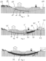
- This first process step is in Figure 1 shown.
- each DSE 31 has at least one nozzle 33 and an external thread 19 or an internal thread 21 at its ends. This allows each DSE 31 to be connected to a drill rod 17 or to another DSE 31.
- the drill rod has a first end 35 and a second end 37.
- a binding agent is introduced into the drill rod 15 and the DSE 31 via the second end 37.
- the binding agent is preferably a cement suspension.
- the nozzles 33 of a DSE 31 mix the binding agent with the existing soil, whereby a binding agent column 39 hardens around the borehole 11 and stabilizes the borehole 11. For reasons of redundancy, several DSE 31s are arranged one behind the other. If the nozzles 33 of a DSE 31 become clogged, another DSE 31 with functioning nozzles 33 can be put into operation.
- the nozzles 33 of a DSE 31 are opened and closed via a valve 41.
- the valve 41 is controlled, for example, via a control line, compressed air, a radio signal, mechanically, or a retraction movement.
- the control line can be implemented via the first end 35 in the drill rod 15.
- the valve 41 can receive compressed air if a flap 42 is opened on the drill rod 17 connected to the DSE 31. If a nozzle 33 becomes clogged in the middle of the borehole 11, the drill rod 15 does not have to be completely pulled out of the borehole, but another DSE 31 can be activated.
- a nozzle 31 has a diameter of 2.5 to 6 mm.
- the DSE 31 are pulled from the target pit 27 into the starting pit 25 ( Figure 2 ).
- the entire borehole is reinforced with a binder column 39. Settlement of the soil and the surface is therefore reliably prevented by the binder column 39.
- the soil where the borehole 11 is located is saturated with the binder and groundwater can no longer penetrate into the soil and warp or wash it away.
- a coupling element 43 is provided, which is shown in detail Y in Figure 11
- the binding agent is provided in a mixing plant 45 with cement from a silo 47 and water as a suspension.
- the coupling element 43 enables the binding agent to be introduced through the fixed feed line 49 from the mixing plant 45 into the rotating drill rod 15 by allowing the drill rod 15 to rotate in the coupling element 43.
- the jet grouting process can be a high-pressure injection (HDI) or a low-pressure injection (NDI).
- HDI high-pressure injection
- NDI low-pressure injection
- the binding agent is injected into the existing soil at up to 550 bar. Due to the high pressure, the jet cuts open the grain structure of the soil and mixes it with the binding agent.
- HDI can be carried out in a 1-, 2- or 3-phase process. The binding agent can therefore be injected alone, or with air or water, or with air and water.
- NDI can also be used. With NDI, a pressure of no more than 200 bar is sufficient and this method is therefore more cost-effective.
- the drill rod 15 Since the binding agent column 39 must harden, the drill rod must remain in the borehole for up to 24 hours. To prevent the drill rod from sticking to the binding agent 39 during this time, the drill rod 15 is constantly rotated and moved back and forth linearly by up to 7 m. Removal wings 51 are formed on the coupling ends 50 of the drill rods 17 (see detail Z shown in Figure 12 ). The removal blades 51 can cut the drill rods 17 free from the binding agent by the rotation of the drill rod 15.
- the now hardened borehole can be widened in one or more stages.
- a reamer 52 is integrated into the drill rod 15 and pulled through the borehole 11. If required, this process can be repeated with further reamers 52 with a larger diameter. This allows boreholes 11 to be created with a borehole diameter of up to 100 cm ( Figure 4 ).
- a control cleaner can be pulled through the borehole 11. It is also conceivable to pull a piece of the product pipe 53 to be laid later, with a length of, for example, 5 m, through the borehole 11. If this piece can be pulled through the borehole, it can be assumed that the product pipe 53 can be pulled into the borehole 11 over the entire length. In Figure 5 the borehole 11 is shown, which is now cleaned and inspected and is ready for the insertion of the product pipe 53.
- the product pipe 53 can be a protective pipe for other pipes, cables or a district heating line. However, it can also be the direct carrier pipe, e.g. of a water or gas line.
- the cavity 55 between the binder column 39 or the borehole 11 and the product pipe 53 is filled with a filling material 54 To do this, as in Figure 7 shown, the filling material 54 is pumped into the cavity 55 by a pump 57.
- FIG 8 an embodiment of the method is shown which can be used in safe geological conditions. Bentonite flushing during drilling of the borehole can be dispensed with and the injection of binding agent after the HDI or NDI can take place during drilling. This means that two work steps can be carried out simultaneously, which makes it possible to save a significant amount of time.
- a plurality of DSE 31 can be coupled directly to the drill head 13 and the drill rod 15 can be coupled to the last DSE 31. The resulting drilling cuttings can be split by the HDI and therefore do not have to be transported out of the borehole.
- the embodiment according to the Figure 9 is used when the soil is extremely dense and saturated.
- a reamer 52 on the drill rod 15 is pulled through the borehole 11 several times and the area around 59 of the borehole 11 is rinsed several times with bentonite. This creates space in the soil or loosens it so that the binding agent can be injected into it.
- FIG. 13 to 15 an application of the horizontal drilling method described above is shown to create a tunnel 60: A plurality of boreholes 11 are drilled and binder columns 39 are created by HDI or NDI to create a tunnel arch 61. After the tunnel arch 61 has been created, the soil within the tunnel arch 61 can be removed ( Figure 14 ). The binder columns 39 can then be reinforced with anchors 63. Finally, the tunnel arch 61 can be clad with a cladding 65, preferably made of shotcrete.
- FIG. 16 A further application of the inventive drilling method is in the Figures 16 to 18 shown to carry out a subsoil stabilization beneath a building 66:
- a strand 67 can be pulled into the borehole with the drill rod 15.
- the strand 67 can be a steel cable with head plates at the ends.
- the strand 67 is tensioned and anchored at its ends outside the borehole 11.
- the remaining cavity in the borehole 11 is filled with a filling material 54.
- the strand 67 can stabilize the subsoil and stop the subsidence.
- the present horizontal drilling method makes it possible to produce stable boreholes 11 without digging trenches, even when the ground is unstable and therefore the horizontal directional drilling method cannot be used.
- the consolidation of the ground is achieved by a binder column 39, which is created by injecting a binder into the ground using a jet grouting method.
Landscapes
- Engineering & Computer Science (AREA)
- Life Sciences & Earth Sciences (AREA)
- Geology (AREA)
- Mining & Mineral Resources (AREA)
- Physics & Mathematics (AREA)
- Environmental & Geological Engineering (AREA)
- Fluid Mechanics (AREA)
- General Life Sciences & Earth Sciences (AREA)
- Geochemistry & Mineralogy (AREA)
- Mechanical Engineering (AREA)
- Piles And Underground Anchors (AREA)
- Consolidation Of Soil By Introduction Of Solidifying Substances Into Soil (AREA)
Description
- Die Erfindung betrifft eine Horizontalbohrverfahren gemäss Oberbegriff des Anspruchs 1 und ein Horizontalbohrsystem gemäss Oberbegriff des Anspruchs 14.
- Das übliche Verfahren im Tiefbau zur Herstellung eines Bohrloches zur Verlegung von unterirdischen Rohrleitungen mit einem Durchmesser von bis zu 1000 mm ist das Horizontalspülbohrverfahren. Da bei diesem Verfahren die Aushebung eines Grabens vermieden werden kann, ist es besonders für die Unterquerung von fließenden Gewässern, Straßen und Autobahnen usw. geeignet.
- Die Horizontalspülbohranlage bohrt mit einem Bohrkopf eine Pilotbohrung von einer Startgrube in Richtung Zielgrube. Der Bohrkopf ist mit dem aus stückweisem Bohrgestänge zusammengeschraubten Bohrstrang verschraubt, der von der Horizontalspülbohranlage in das Erdreich getrieben wird und eine gewisse Flexibilität aufweist. Ein gegenüber dem Bohrkopf geringerer Durchmesser des Bohrgestänges lässt einen Ringraum frei. Durch das Gestänge wird eine Bentonit-Bohrspülung zum Bohrkopf gepumpt, wo sie austritt und das Bohrklein durch den Ringraum ausspült. Neben dem Ausspülen von Bohrklein stellt die Bohrspülung auch die Stützung des Bohrloches sicher und dichtet die Bohrlochwand ab. Zusätzlich dient sie durch die speziellen Eigenschaften von Bentonit dem Kühlen des Bohrkopfes und als Schmiermittel.
- Hat der Bohrkopf die Zielgrube erreicht, wird er gegen einen sogenannten Räumer ausgetauscht. Der Räumer hat einen größeren Durchmesser als der Bohrkopf und weitet beim Zurückziehen die Pilotbohrung auf unter gleichzeitiger Verdichtung der Bohrungswände. Je nach Bodenbeschaffenheit wird mehr Bohrklein ausgetragen oder mehr verdrängt. An den Räumer angehängt kann entweder für weitere Aufweitungsschritte nochmals ein Bohrstrang oder abschließend ein oder mehrere Rohre in den Bohrkanal eingezogen werden.
- Die
US 5 979 574 A ,US2018/163475 A1 ,US 9 828 805 B2 DE 297 03 655 U1 beschreiben ein solches Horizontalspülbohrverfahren. - Es gibt jedoch geologische Zusammensetzungen des Bodens, bei welchen sich das Horizontalspülbohrverfahren nicht zur Herstellung eines Durchbruches eignet. Dies ist insbesondere dann der Fall, wenn der Boden instabil ist und die Gefahr von Setzungen nach der Bohrung besteht. Auch kann es sein, dass der Boden den Durchbruch nach der Bohrung sofort wieder verkleinert, sodass die Kräfte am Räumer zu gross sind, um diesen durch den Durchbruch zu führen bzw. das Bohrloch in sich zusammenfällt und einen Rohreinzug unmöglich macht.
- Zur Verfestigung des Bohrloches wird in der
DE 297 03 655 U1 vorgeschlagen einen elastomeren Formkörper in das Bohrgestänge einzubinden. Der Formkörper verdichtet das Erdreich rund um die aufgeweitete Bohrlochwandung. - Aus den Nachteilen des beschriebenen Stands der Technik resultiert die Aufgabe, ein Horizontalbohrverfahren zu zeigen, welches auch bei den oben beschriebenen instabilen Bodenverhältnissen eingesetzt werden kann.
- Die Lösung der gestellten Aufgabe gelingt bei einem Horizontalbohrverfahren durch die im kennzeichnenden Abschnitt des Patentanspruchs 1 angeführten Merkmale. Weiterbildungen und/oder vorteilhafte Ausführungsvarianten sind Gegenstand der abhängigen Patentansprüche.
- Die Erfindung ist durch die Einbindung wenigstens eines Düsenstrahlelements (DSE) in das Bohrgestänge gekennzeichnet, mit welchem DSE in dem Bohrgestänge eingeleitetes Bindemittel in den das Bohrloch umgebenden Boden mit einem Düsenstrahlverfahren vor dem Schritt 3) oder während des Schrittes 1) injiziert wird, wodurch rund um das Bohrloch eine Bindemittelsäule entsteht. Das Verfahren ermöglicht es, Horizontalbohrungen in instabilem Boden durzuführen, was mit Verfahren des Stands der Technik nicht möglich ist. Bei den bekannten Verfahren wird das Bohrloch bei solchen Böden instabil oder kollabiert schlechtestenfalls. Instabile Böden, welche für Verfahren des Stands der Technik ungeeignet sind, in welche mit dem vorliegenden Verfahren jedoch ein stabiles Bohrloch gebohrt werden kann, enthalten beispielsweise Rheinkies oder Grobschotter ohne nennenswerten Feinkornanteil. Das Verfahren ermöglicht es, dass ein im Wesentlichen horizontales Bohrloch auch in instabilem Boden herstellbar ist, ohne dass das Bohrloch Gefahr läuft sich zu setzen. Setzungen an der Oberfläche des Bodens sind daher jedenfalls vermieden. Da der anstehende Boden durch die Bindemittelsäule gesättigt ist, kann Grundwasser den Boden um das Bohrloch nicht ausspülen und nicht destabilisieren. Wenn es die Stabilität des Bodens zulässt, kann wenigstens eine DSE zwischen dem Bohrkopf und dem Bohrgestänge eingesetzt werden. Dadurch können die Arbeitsschritte 1) und 2) gleichzeitig erfolgen.
- Als zweckdienlich hat es sich erwiesen, wenn das Düsenstrahlverfahren eine Hochdruckinjektion (HDI) oder eine Niederdruckinjektion (NDI) ist. Um eine stabile Bindemittelsäule aufbauen zu können, muss das Korngerüst des anstehenden Erdreiches aufgeschnitten werden. Dies erfolgt durch den Düsenstrahl bei der HDI mit bis zu 750 bar. Falls der Boden derart beschaffen ist, dass der Bohrkopf das Korngerüst aufschneiden kann, ist es möglich auf die NDI zurückzugreifen, bei welcher Drücke von nur bis zu 250 bar zur Anwendung kommen. Dadurch lässt sich je nach Bodenbeschaffenheit das passende Düsenstrahlverfahren wählen.
- Zweckmässigerweise ist das Bindemittel eine Zementsuspension. Diese Suspension dringt in den Boden ein und bildet zusammen mit dem aufgeschnittenen Korngerüst eine stabile Bindemittelsäule rund um das Bohrloch.
- In einer besonders bevorzugten Ausführungsform der Erfindung ist eine Mehrzahl von Düsenstrahlelementen hintereinander in das Bohrgestänge integriert und über das erste Ende des Bohrgestänges, welche frei von der Bindemittelzuleitung ist, wird das Öffnen und Schliessen der Düsen eines DSE gesteuert. Ein bestehendes Bohrsystem kann daher durch die speziellen DSE mit wenig Aufwand ergänzt werden. Diese müssen lediglich zwischen zwei Bohrstangen eingeschraubt werden. Dabei kann jedes vorhandene Enden des Bohrgestänges genutzt werden, um das Herstellen der Bindemittelsäule kontinuierlich und unterbrechungsfrei zu ermöglichen. Fällt ein DSE aus, da beispielsweise eine Düse verstopft ist, so kann jederzeit auf ein weiteres DSE zurückgegriffen werden.
- Als vorteilhaft erweist es sich, wenn zwischen dem zweiten Ende des Bohrgestänges, an welchem das Bindemittel eingeleitet wird, und der Bindemittelzuleitung aus einer Mischanlage ein Kupplungselement vorgesehen ist, in welchem Kupplungselement sich das Bohrgestänge drehen kann. Das Kupplungselement stellt die Verbindung zwischen der starren Bindemittelzuleitung und dem sich drehenden Bohrgestänge her.
- Die Erfindung zeichnet sich auch bevorzugt dadurch aus, dass das Bohrgestänge während der Erhärtungszeit des Bindemittels über eine Distanz von höchstens 7 m hin- und her verschoben und rotiert wird. Während der Erhärtungszeit der Bindemittelsäule kann das Bohrgestänge nicht an dem Bindemittel haften und kann nach der Erhärtungszeit weiterhin gedreht und rotiert werden.
- Zur Verhinderung des Anhaftens an dem Bindemittel sind an den Kupplungsenden der Rohrstangen Abtragsflügel vorgesehen, welche Bindemittel auf der gesamten Länge des Bohrloches während der Aushärtungszeit abtragen. Dadurch wird das Bohrgestänge sukzessive «freigeschnitten» und bleibt jederzeit beweglich.
- In einer weiteren bevorzugten Ausführungsform der Erfindung wird das Bohrloch nach dem Schritt 1) mit einem Räumer aufgeweitet und mit Bentonit gespült wird. Dadurch lässt sich dichter und gesättigter Boden, in welchen von vorneherein kein Bindemittel injizierbar ist, mit Bentonit aufgelockert und ausgeschwemmt. Dadurch kann in dem anstehenden Boden Platz für das Bindemittel geschaffen werden.
- Zweckmässigerweise wird das Bohrloch nach dem Schritt 3) oder 4) kontrolliert und gereinigt. Dieser Arbeitsschritt wird als «Cleangang» bezeichnet. Dadurch kann ein Steckenbleiben eines Produkterohres beim Einziehen verhindert werden oder andere Fehler in dem Bohrloch erkannt werden.
- Vorteilhaft ist es, wenn nach dem Schritt 3) oder 4) ein Produkterohr mittels des Bohrgestänges in das Bohrloch eingezogen wird. Dadurch dient das Bohrverfahren einer Rohrverlegung mit allen Vorteilen des Horizontalspülbohrverfahrens, jedoch auch in instabilen Böden.
- Mit Vorteil erfolgt die Kontrolle und Reinigung des Bohrloches dadurch, dass ein Produkterohr von höchstens 5 m Länge durch das Bohrloch gezogen wird. Wenn dieses Proberohr sich vollständig durch das Bohrloch ziehen lässt, so ist davon auszugehen, dass auch das gesamte Produkterohr in das Bohrloch einziehbar ist. Zusätzlich kann das Proberohr Verunreinigungen aus dem Bohrloch fördern.
- Dadurch, dass mit Vorteil ein zwischen der Bindemittelsäule und dem Produkterohr vorhandener Hohlraum mit einem Füllmaterial verfüllt wird, können Setzungen im Boden und an der Oberfläche zuverlässig verhindert werden. Solche Setzungen sind jedoch sehr unwahrscheinlich, da die Bindemittelsäule ohnedies sehr stabil und setzungssicher ist.
- In einer bevorzugten Ausführungsform zur Herstellung eines Tunnels werden eine Mehrzahl von Bohrlöchern entlang eines Tunnelbogens gebohrt, deren Bindemittelsäulen einander berühren, wird das Erdreich innerhalb des Tunnelbogens entfernt, wird der Tunnelbogen mit Verankerungen die Bindemittelsäulen durchdringend armiert und wird der Tunnelbogen mit Spritzbeton verkleidet. Dadurch lässt sich mit geringem Aufwand unter Verwendung des vorliegenden Horizontalbohrverfahrens ein Tunnel mit einer Länge bis zu 1 km herstellen. Auf eine Tunnelbohrmaschine, welche in der Herstellung und im Betrieb sehr teuer ist, kann verzichtet werden.
- In einer bevorzugten Ausführungsform zur Baugrundstabilisierung unterhalb eines gesetzten Gegenstandes, insbesondere eines Gebäudes, wird ein Bohrloch und eine Bindemittelsäule erstellt, wird in das Bohrloch eine Litze eingezogen, wird die Litze an ihren beiden Enden gespannt und verankert und wird der in dem Bohrloch verbleibende Hohlraum mit einem Füllmaterial verfüllt. Dadurch lässt sich mit geringem Aufwand der Setzungsvorgang des Erdreiches unterhalb eines Gebäudes stoppen und die weitere Absenkung des Gebäudes verhindern.
- Ein weiterer Aspekt der Erfindung betrifft ein Horizontalbohrsystem zur Durchführung eines Horizontalbohrverfahrens nach der obigen Beschreibung und gemäss dem Oberbegriff des Anspruches 14. Die Erfindung zeichnet sich auch dadurch aus, dass zwischen zwei benachbarte Bohrstangen wenigstens ein DSE mit wenigstens einer Düse an seinem Mantel und bevorzugt mehrere miteinander verbundene DSE anordenbar sind, wobei eine der Bohrstangen über das erste Ende des Bohrgestänges der Steuerung des Verschlusses bzw. der Öffnung der Düsen dient und die andere Bohrstange über das zweite Ende des Bohrgestänges der Versorgung der DSE mit Bindemittel dient. Dadurch ist das bestehende Bohrgestänge optimal zum Betrieb der HDI oder der NDI nutzbar. Zusätzlich lässt sich der Ausfall einer DSE sofort durch Inbetriebnahme einer weiteren DSE kompensieren. Das aufwendige Ausziehen des Bohrgestänges und der Austausch der kaputten DSE gegen eine funktionstüchtige DSE kann dadurch vermieden werden.
- In einer weiteren bevorzugten Ausführungsform der Erfindung sind an den Kupplungsenden der Bohrstangen Abtragsflügel ausgebildet, deren Umfangskreis einen grösseren Durchmesser als das jeweilige Kupplungsende aufweisen. Dadurch lässt sich das Bohrgestänge während der Aushärtung der Bindemittelsäule durch ständige Rotation freischneiden.
- Zweckmässigerweise weist das System zur Bindemittelzuleitung aus einer Mischanlage ein Kupplungselement auf, durch welches das Bindemittel in das zweite Ende des Bohrgestänges eingeleitet wird und in welchem Kupplungselement sich das Bohrgestänge abgedichtet drehen kann. Durch das Kupplungselement lässt sich eine Verbindung zwischen der feststehenden Bindemittelzuleitung und dem sich drehenden Bohrgestänge herstellen.
- Weitere Vorteile und Merkmale ergeben sich aus der nachfolgenden Beschreibung mehrerer Ausführungsbeispiele der Erfindung unter Bezugnahme auf die schematischen Darstellungen. Die folgenden Prinzipskizzen zeigen in nicht massstabsgetreuer Darstellung:
- Figur 1:
- erstellen einer Pilotbohrung;
- Figur 2:
- erstellen einer Bindemittelsäule;
- Figur 3:
- abwarten der Erhärtungszeit;
- Figur 4:
- aufweiten des Bohrloches;
- Figur 5:
- kontrollieren und reinigen des Bohrloches;
- Figur 6:
- einziehen des Produkterohres;
- Figur 7:
- auffüllen des Hohlraumes rund um das Produkterohr;
- Figur 8:
- gleichzeitiges erstellen der Pilotbohrung und der Bindemittelsäule;
- Figur 9:
- aufweiten des Bohrloches nach Erstellung der Pilotbohrung;
- Figur 10:
- Anordnung mehrerer Düsenstrahlelemente (Detail X);
- Figur 11:
- Einleitung des Bindemittels (Detail Y);
- Figur 12:
- Bohrstangendetail mit Abtragsflügeln (Detail Z);
- Figur 13:
- Tunnel mit einer Mehrzahl von Bohrlöchern mit Bindemittelsäule
- Figur 14:
- ausgebrochener Tunnel
- Figur 15:
- armierter Tunnelbogen
- Figur 16:
- Pilotbohrung unter einem gesetzten Gebäude
- Figur 17:
- Bohrloch mit einer verlegten Litze und
- Figur 18
- Litze im verfüllten Bohrloch
- In den
Figuren 1 bis 10 und13 bis 18 ist ein Bohrloch gezeigt, welches gesamthaft mit dem Bezugszeichen 11 bezeichnet ist. Das Bohrloch 11 wird erstellt, ohne dass dafür ein Graben ausgehoben werden muss, da ein Horizontalbohrverfahren zur Anwendung kommt. Zur Erstellung des Bohrloches 11 wird eine Pilotbohrung vorgenommen. Dazu wird ein Bohrkopf 13 an der Spitze eines Bohrgestänges 15 in den Boden getrieben. Das Bohrgestänge 15 wird durch eine Mehrzahl von aneinander gekuppelten Bohrstangen 17 erstellt. Die zugewandten Seiten von benachbarten Bohrstangen 17 können beispielsweise ineinander geschraubt werden. Dazu besitzt eine Bohrstange ein Aussengewinde 19 und die andere Bohrstange ein Innengewinde 21. Die jeweilige Verschieberichtung des Bohrgestänges 15 wird in den Figuren mit einem Pfeil angezeigt. - Ein Bohrgerät 23 versetz das Bohrgestänge 15 und den Bohrkopf 13 in Rotation, wodurch der Bohrkopf von einer Startgrube 25 ausgehend in Richtung einer Zielgrube 27 getrieben wird. Dabei wird das Bohrgestänge 15 sukzessive um eine weitere Bohrstange 17 verlängert bis der Bohrkopf 13 die Zielgrube 27 erreicht. Während des Bohrvorganges wird in das Bohrgestänge 15 Bentonit aufgegeben, welcher den Bohrkopf 13 kühlt und schmiert und das Bohrklein aus dem Bohrloch ausspült. Die austretende Bohrspülung ist mit Bohrklein angereichert und sammelt sich in der Startgrube, von welcher sie über die Recyclinganlage wieder zur Mischanlage gepumpt wird. In einer Recyclinganlage 29 wird ausgetragenes Bohrklein von der Bentonitspülung getrennt, damit die Bohrspülung wiederverwendet werden kann. Dieser erste Verfahrensschritt ist in
Figur 1 gezeigt. - Ist die Geologie des Bodens, in welchen das Bohrloch 11 getrieben wird, instabil, so ist die Anwendung der bekannten Horizontalspülbohrtechnik nicht möglich, weil das Bohrloch instabil ist. Beispielsweise führt das Auftreten von Rheinkies im Boden zu solchen instabilen Verhältnissen.
- Um das Bohrloch stabil zu machen, wird folgender Verfahrensschritt vorgenommen: Nachdem der Bohrkopf 13 die Zielgrube erreicht hat, wird er abmontiert und wenigstens ein Düsenstrahlelement (DSE) 31 wird an das Bohrgestänge 15 angekuppelt. Diese Anordnung ist im Detail X in
Figur 10 gezeigt. Jedes DSE 31 besitzt zumindest eine Düse 33 und an seinen Enden ein Aussengewinde 19 bzw. ein Innengewinde 21. Dadurch kann jedes DSE 31 mit einer Bohrstange 17 oder an einem weiteren DSE 31 verbunden werden. In einer solchen Anordnung hat das Bohrgestänge ein erstes Ende 35 und ein zweites Ende 37. Über das zweite Ende 37 wird ein Bindemittel in das Bohrgestänge 15 und die DSE 31 eingeleitet. Bevorzugt ist das Bindemittel eine Zementsuspension. Über die Düsen 33 eines DSE 31 wird das Bindemittel mit dem anstehenden Boden vermischt, wodurch eine Bindemittelsäule 39 rund um das Bohrloch 11 aushärtet und das Bohrloch 11 stabilisiert. Aus Gründen der Redundanz sind mehrere DSE 31 hintereinander angeordnet. Falls die Düsen 33 eines DSE 31 verstopfen, so kann ein weiteres DSE 31 mit funktionsfähigen Düsen 33 in Betrieb genommen werden. Das Öffnen bzw. Schliessen der Düsen 33 eines DSE 31 erfolgt über ein Ventil 41. Das Ventil 41 wird beispielsweise über eine Steuerleitung, Druckluft, ein Funksignal, mechanisch, oder eine Rückzugsbewegung angesteuert. Die Steuerleitung kann über das erste Ende 35 in dem Bohrgestänge 15 realisiert sein. Das Ventil 41 kann Druckluft erhalten, wenn an der an die DSE 31 anschliessende Bohrstange 17 eine Klappe 42 geöffnet wird. Falls also eine Düse 33 schlechtestenfalls mitten in dem Bohrloch 11 verstopft, so muss das Bohrgestänge 15 nicht vollständig aus dem Bohrloch herausgezogen werden, sondern es kann ein weiteres DSE 31 aktiviert werden. Eine Düse 31 besitzt einen Durchmesser von 2,5 bis 6 mm. - Die DSE 31 werden von der Zielgrube 27 in die Startgrube 25 gezogen (
Figur 2 ). Wenn die DSE 31 die Startgrube 25 erreicht haben, ist das gesamte Bohrloch mit einer Bindemittelsäule 39 verstärkt. Setzungen des Bodens und der Oberfläche sind daher durch die Bindemittelsäule 39 zuverlässig verhindert. Zudem ist der Boden, an dem das Bohrloch 11 ansteht, durch das Bindemittel gesättigt und Grundwasser kann in den Boden nicht mehr eindringen und diesen verziehen oder ausschwemmen. - Damit das Bindemittel in das drehende Bohrgestänge 15 aufgegeben werden kann, ist ein Kupplungselement 43 vorgesehen, welches im Detail Y in
Figur 11 gezeigt ist. Das Bindemittel wird in einer Mischanlage 45 mit Zement aus einem Silo 47 und Wasser als eine Suspension zur Verfügung gestellt. Das Kupplungselement 43 ermöglicht, dass das Bindemittel durch die feststehende Zuleitung 49 aus der Mischanlage 45 in das drehende Bohrgestänge 15 eingeleitet werden kann, indem sich das Bohrgestänge 15 in dem Kupplungselement 43 drehen kann. - Je nach der vorhandenen Bodenbeschaffenheit kann das Düsenstrahlverfahren eine Hochdruckinjektion (HDI) oder eine Niederdruckinjektion (NDI) sein. Bei der HDI wird das Bindemittel mit bis zu 550 bar in den anstehenden Boden eingebracht. Durch den hohen Druck schneidet der Düsenstrahl das Korngerüst des Bodens auf und vermischt dieses mit dem Bindemittel. Die HDI kann im 1-, 2- oder 3 Phasenverfahren erfolgen. Das Bindemittel kann also allein, oder mit Luft oder Wasser oder mit Luft und Wasser injiziert werden.
- Falls der Boden derart beschaffen ist, dass der Bohrkopf das Korngerüst aufschneiden kann, so kann auch mit der NDI gearbeitet werden. Bei der NDI ist ein Druck von höchstens 200 bar ausreichend und dieses Verfahren ist dementsprechend kostengünstiger.
- Da die Bindemittelsäule 39 aushärten muss, muss das Bohrgestänge während bis zu 24 h in dem Bohrloch bleiben. Damit das Bohrgestänge während dieser Zeit nicht an dem Bindemittel 39 anhaftet, wird das Bohrgestänge 15 ständig gedreht und um bis zu 7 m linear hin- und her bewegt. An den Kupplungsenden 50 der Bohrstangen 17 sind Abtragsflügel 51 ausgebildet (Siehe Detail Z dargestellt in
Figur 12 ). Die Abtragsflügel 51 können durch die Rotation des Bohrgestänges 15 die Bohrstangen 17 aus dem Bindemittel freischneiden. - Das nunmehr ausgehärtete Bohrloch kann in einer oder mehreren Stufen aufgeweitet werden. Dazu wird ein Räumer 52 in das Bohrgestänge 15 integriert und durch das Bohrloch 11 gezogen. Nach Bedarf kann dieser Vorgang mit weiteren Räumern 52 mit grösserem Durchmesser wiederholt werden. Dadurch können Bohrlöcher 11 mit einem Bohrlochdurchmesser bis zu 100 cm erstellt werden (
Figur 4 ). - Zur Kontrolle und Reinigung des fertigen Bohrloches 11 kann ein Kontrollräumer durch das Bohrloch 11 gezogen werden. Denkbar ist auch ein Stück des später zu verlegenden Produkterohres 53 mit einer Länge von beispielsweise 5 m durch das Bohrloch 11 zu ziehen. Wenn sich dieses Stück durch das Bohrloch ziehen lässt, so ist davon auszugehen, dass das Produkterohr 53 über die gesamte Länge des Bohrloches 11 in dieses einziehen lässt. In
Figur 5 ist das Bohrloch 11 gezeigt, welches nunmehr gesäubert und kotrolliert ist und bereit für den Einzug des Produkterohres 53 ist. - In
Figur 6 ist der Einzug des Produkterohres 53 gezeigt. Durch das Vorhandensein der Bindemittelsäule 39 und deren Stabilisierung des Bohrloches 11 muss das Produkterohr 53 nicht möglichst rasch eingezogen werden, wie dies bei Verfahren des Stands der Technik notwendig ist. Vielmehr kann der Einziehvorgang unterbrochen werden und es herrscht kein Zeitdruck beim Verschweissen der einzelnen Produkterohrstücke. Daher muss das Produkterohr 53 auch nicht vollständig ausgelegt und bereit für den Einzug sein, wenn das Bohrloch 11 fertiggestellt ist. Das Produkterohr 53 kann ein Schutzrohr für andere Rohre, Kabel oder eine Fernwärmeleitung sein. Es kann aber auch direkt das Mediumrohr z.B. einer Wasser- oder Gasleitung sein. - Damit sicher keine Setzungen entstehen, wird der Hohlraum 55 zwischen der Bindemittelsäule 39 bzw. dem Bohrloch 11 und dem Produkterohr 53 mit einem Füllmaterial 54 verfüllt. Dazu wird, wie in
Figur 7 gezeigt, das Füllmaterial 54 mit einer Pumpe 57 in den Hohlraum 55 gefördert. - In
Figur 8 ist eine Ausführungsform des Verfahrens gezeigt, welche bei sicheren geologischen Verhältnissen angewendet werden kann. Dabei kann auf eine Bentonitspülung während des Bohrens des Bohrloches verzichtet werden und die Injektion mit Bindemittel nach der HDI oder NDI kann während des Bohrens erfolgen. Dadurch können 2 Arbeitsschritte gleichzeitig erfolgen, wodurch eine signifikante Zeiteinsparung möglich ist. Zur Durchführung dieser Ausführungsform kann direkt an dem Bohrkopf 13 eine Mehrzahl von DSE 31 angekuppelt sein und an das letzte DSE 31 kann das Bohrgestänge 15 angekuppelt sein. Das entstehende Bohrklein kann durch die HDI gespalten werden und muss daher nicht aus dem Bohrloch abtransportiert werden. - Die Ausführungsform gemäss der
Figur 9 wird angewendet, wenn der Boden äusserst dicht und gesättigt ist. Dabei wird ein Räumer 52 an dem Bohrgestänge 15 mehrmals durch das Bohrloch 11 gezogen und die Umgebung 59 des Bohrloches 11 mehrmals mit Bentonit gespült. Dadurch entsteht Platz im Boden bzw. er wird aufgelockert, um das Bindemittel in diesen injizieren zu können. - In den
Figuren 13 bis 15 ist eine Anwendung des oben beschriebenen Horizontalbohrverfahrens gezeigt, um einen Tunnel 60 herzustellen: Dabei werden eine Mehrzahl von Bohrlöchern 11 gebohrt und Bindemittelsäulen 39 durch HDI oder NDI erstellt, um einen Tunnelbogen 61 zu erzeugen. Nach Erzeugung des Tunnelbogens 61 kann das Erdreich innerhalb des Tunnelbogens 61 entfernt werden (Figur 14 ). Anschliessend können in die Bindemittelsäulen 39 mit Verankerungen 63 armiert werden. Abschliessend kann der Tunnelbogen 61 mit einer Verkleidung 65, bevorzugt aus Spritzbeton, verkleidet werden. - Auf diese Weise können Verkehrstunnel, Entlastungstollen oder unterirdische Kanäle bis zu einer Länge von 1 km erstellt werden.
- Eine weitere Anwendung des erfinderischen Bohrverfahrens ist in den
Figuren 16 bis 18 gezeigt, um eine Baugrundstabilisierung unterhalb eines Gebäudes 66 vorzunehmen: Nachdem das Bohrloch 11 und die Bindemittelsäule 39, wie weiter oben beschrieben, hergestellt sind (Figur 16 ), kann in das Bohrloch eine Litze 67 mit dem Bohrgestänge 15 eingezogen werden. Die Litze 67 kann ein Stahlseil mit Kopfplatten an den Enden sein. Die Litze 67 wird gespannt und an ihren Enden ausserhalb des Bohrloches 11 verankert. Dann wird der verbleibende Hohlraum in dem Bohrloch 11 mit einem Füllmaterial 54 verfüllt. Durch die Litze 67 kann der Baugrund stabilisiert werden und die Setzung kann gestoppt werden. - Das vorliegende Horizontalbohrverfahren ermöglicht es stabile Bohrlöcher 11, ohne das Ausheben von Gräben herzustellen, auch wenn der Boden instabil ist und deshalb das Horizontalspülbohrverfahren nicht angewendet werden kann. Die Verfestigung des Bodens wird durch eine Bindemittelsäule 39 erreicht, welche durch Injektion eines Bindemittels in den Boden mit einem Düsenstrahlverfahren erzeugt wird.
-
- 11
- Bohrloch
- 13
- Bohrkopf
- 15
- Bohrgestänge
- 17
- Bohrstange
- 19
- Aussengewinde
- 21
- Innengewinde
- 23
- Bohrgerät
- 25
- Startgrube
- 27
- Zielgrube
- 29
- Recyclinganlage
- 31
- Düsenstrahlelement
- 33
- Düse
- 35
- Erstes Ende des Bohrgestänges
- 37
- Zweites Ende des Bohrgestänges
- 39
- Bindemittelsäule
- 41
- Ventil
- 42
- Klappe
- 43
- Kupplungselement
- 45
- Mischanlage
- 47
- Silo
- 49
- Zuleitung
- 50
- Kupplungsenden
- 51
- Abtragsflügel
- 52
- Räumer
- 53
- Produkterohr
- 54
- Füllmaterial
- 55
- Hohlraum
- 57
- Pumpe
- 59
- Umgebung des Bohrloches im Boden
- 60
- Tunnel
- 61
- Tunnelbogen
- 63
- Verankerungen
- 65
- Verkleidung
- 66
- Gebäude
- 67
- Litze
Claims (16)
- Horizontalbohrverfahren die folgenden Arbeitsschritte aufweisend1) Erstellen einer Pilotbohrung bei welcher ein Bohrkopf (13) an einem Bohrgestänge (15) mit einer Mehrzahl von hintereinander gekuppelten Bohrstangen (17), von einer Startgrube (25) zu einer Zielgrube (27) im Boden getrieben wird und Bentonit über das Bohrgestänge (15) zum Bohrkopf (13) gefördert wird, wodurch ein Bohrloch (11) entsteht,3) Austauschen des Bohrkopfes (13) durch einen Räumer (52) in der Zielgrube (27) und Aufweiten des Bohrloches (11) durch Ziehen des Räumers (52) von der Zielgrube (27) zur Startgrube (25) und4) Optionale Wiederholung des Schrittes 3) mit weiteren Räumern zur stufenweisen Aufweitung des Bohrloches (11)
weiter gekennzeichnet durch2) Einbindung mehrere mit einander verbundene Düsenstrahlelemente (DSE) (31) in das Bohrgestänge (15), mit welche in dem Bohrgestänge (15) zusätzlich zum Betonit eingeleitetes Bindemittel, insbesondere eine Zementsuspension, in den das Bohrloch (11) umgebenden Boden mit einem Düsenstrahlverfahren vor dem Schritt 3) oder während des Schrittes 1) injiziert wird, wodurch rund um das Bohrloch (11) eine ausgehärtete Bindemittelsäule (39) entsteht. - Bohrverfahren nach Anspruch 1, dadurch gekennzeichnet, dass das Düsenstrahlverfahren eine Hochdruckinjektion (HDI) oder eine Niederdruckinjektion (NDI) ist.
- Bohrverfahren nach einem der Ansprüche 1 oder 2, dadurch gekennzeichnet, dass eine Mehrzahl von Düsenstrahlelementen (31) hintereinander in das Bohrgestänge (17) integriert ist und über das erste Ende (35) des Bohrgestänges (15), welche frei von der Bindemittelzuleitung ist, das Öffnen und Schliessen der Düsen eines DSE gesteuert wird.
- Bohrverfahren nach einem der vorangehenden Ansprüche, dadurch gekennzeichnet, dass zwischen dem zweiten Ende (37) des Bohrgestänges (15), an welchem das Bindemittel eingeleitet wird, und der Bindemittelzuleitung (49) aus einer Mischanlage (45) ein Kupplungselement (43) vorgesehen ist, in welchem Kupplungselement (43) sich das Bohrgestänge (15) drehen kann.
- Bohrverfahren nach einem der vorangehenden Ansprüche, dadurch gekennzeichnet, dass das Bohrgestänge (15) während der Erhärtungszeit des Bindemittels über eine Distanz von höchstens 7 m hin- und her verschoben und rotiert wird.
- Bohrverfahren nach Anspruch 5, dadurch gekennzeichnet, dass an den Kupplungsenden (50) der Bohrstangen (17) Abtragsflügel (51) vorgesehen sind, welche Bindemittel auf der gesamten Länge des Bohrloches (11) während der Aushärtungszeit abtragen.
- Bohrverfahren nach einem der vorangehenden Ansprüche, dadurch gekennzeichnet, dass das Bohrloch (11) nach dem Schritt 1) mit einem Räumer (52) aufgeweitet wird und mit Bentonit gespült wird.
- Bohrverfahren nach einem der vorangehenden Ansprüche, dadurch gekennzeichnet, dass das Bohrloch (11) nach dem Schritt 3) oder 4) kontrolliert und gereinigt wird.
- Bohrverfahren nach einem der vorangehenden Ansprüche, dadurch gekennzeichnet, dass nach dem Schritt 3) oder 4) ein Produkterohr (53) mittels des Bohrgestänges (15) in das Bohrloch (11) eingezogen wird.
- Bohrverfahren nach Anspruch 9, dadurch gekennzeichnet, dass die Kontrolle und Reinigung des Bohrloches (11) dadurch erfolgt, dass ein Produkterohr (53) von höchstens 5 m Länge durch das Bohrloch (11) gezogen wird.
- Bohrverfahren nach einem der Ansprüche 9 oder 10, dadurch gekennzeichnet, dass ein zwischen der Bindemittelsäule und dem Produkterohr (53) vorhandener Hohlraum (55) mit einem Füllmaterial (54) verfüllt wird.
- Bohrverfahren nach einem der Ansprüche 1 bis 8, dadurch gekennzeichnet, dass zur Herstellung eines Tunnels- eine Mehrzahl von Bohrlöchern (11) entlang eines Tunnelbogens (61) gebohrt werden, deren Bindemittelsäulen (39) einander berühren,- das Erdreich innerhalb des Tunnelbogens (61) entfernt wird,- der Tunnelbogen (61) mit Verankerungen (63) die Bindemittelsäulen (39) durchdringend armiert wird und- der Tunnelbogen (61) mit Spritzbeton verkleidet wird.
- Bohrverfahren nach einem der Ansprüche 1 bis 8, dadurch gekennzeichnet, dass zur Baugrundstabilisierung unterhalb eines gesetzten Gegenstandes, insbesondere eines Gebäudes (66)- ein Bohrloch (11) und eine Bindemittelsäule (31) erstellt wird,- in das Bohrloch (11) eine Litze (67) eingezogen wird,- die Litze (67) an ihren beiden Enden gespannt und verankert wird und- der in dem Bohrloch (11) verbleibende Hohlraum (55) mit einem Füllmaterial (54) verfüllt wird.
- Horizontalbohrsystem zur Durchführung eines Horizontalbohrverfahrens nach einem der vorangehenden Ansprüche aufweisendeine Mehrzahl von Bohrstangen (17), welche sich zu einem Bohrgestänge (15) mit einem ersten und zweiten Ende (35,37) verbunden sind und von einem Bohrgerät (23) angetrieben werden undein DSE (31) mit wenigstens einer Düse (33) an seinem Mantel, welche zwischen zwei benachbarte Bohrstangen (17) angeordnet ist,dadurch gekennzeichnet,dass mehrere miteinander verbundene DSE (31) zwischen zwei benachbarten Bohrstangen hintereinander angeordnet sind und an jedem DSE (31) ein Ventil (41) vorhanden ist, welches die Düsen (31) einer DSE (31) öffnet und schliesst, indem das Ventil (41) durch eine der Bohrstangen (17) über das erste Ende (35) des Bohrgestänges (15) angesteuert ist unddass über die andere Bohrstange (17) über das zweite Ende (37) des Bohrgestänges (15) die DSE (31) mit Bindemittel versorgt ist.
- Horizontalbohrsystem nach Anspruch 14, dadurch gekennzeichnet, dass das System zur Bindemittelzuleitung aus einer Mischanlage (45) ein Kupplungselement (43) aufweist, durch welches das Bindemittel in das zweite Ende (37) des Bohrgestänges (15) eingeleitet wird und in welchem Kupplungselement (43) sich das Bohrgestänge (15) abgedichtet drehen kann.
- Horizontalbohrsystem nach Anspruch 14 oder 15, dadurch gekennzeichnet, dass an den Kupplungsenden (50) der Bohrstangen (17) Abtragsflügel (51) ausgebildet sind, deren Umfangskreis einen grösseren Durchmesser als das jeweilige Kupplungsende (50) aufweisen.
Applications Claiming Priority (1)
| Application Number | Priority Date | Filing Date | Title |
|---|---|---|---|
| CH70251/21A CH718952A1 (de) | 2021-09-07 | 2021-09-07 | Horizontalbohrverfahren und Horizontalbohrsystem. |
Publications (2)
| Publication Number | Publication Date |
|---|---|
| EP4144952A1 EP4144952A1 (de) | 2023-03-08 |
| EP4144952B1 true EP4144952B1 (de) | 2024-11-20 |
Family
ID=85128692
Family Applications (1)
| Application Number | Title | Priority Date | Filing Date |
|---|---|---|---|
| EP22194255.0A Active EP4144952B1 (de) | 2021-09-07 | 2022-09-07 | Horizontalbohrverfahren und horizontalbohrsystem |
Country Status (2)
| Country | Link |
|---|---|
| EP (1) | EP4144952B1 (de) |
| CH (1) | CH718952A1 (de) |
Families Citing this family (1)
| Publication number | Priority date | Publication date | Assignee | Title |
|---|---|---|---|---|
| CN116291488A (zh) * | 2023-04-04 | 2023-06-23 | 湖南大学 | 基于双机联动的曲线钻进全方位高压旋喷注浆系统及方法 |
Family Cites Families (4)
| Publication number | Priority date | Publication date | Assignee | Title |
|---|---|---|---|---|
| DE29703655U1 (de) | 1997-02-28 | 1997-12-04 | Welldone Engineering GmbH, 29355 Beedenbostel | Werkzeug für Horizontalbohrungen |
| US5979574A (en) | 1997-05-13 | 1999-11-09 | Ozzie's Pipeline Padder, Inc. | Horizontal boring apparatus and method of using the same |
| US9828805B2 (en) | 2013-04-10 | 2017-11-28 | The Charles Machine Works, Inc. | Reamer with replaceable cutters |
| US10526846B2 (en) | 2014-03-06 | 2020-01-07 | Barbco, Inc. | Material exhaust connection for horizontal bore |
-
2021
- 2021-09-07 CH CH70251/21A patent/CH718952A1/de unknown
-
2022
- 2022-09-07 EP EP22194255.0A patent/EP4144952B1/de active Active
Also Published As
| Publication number | Publication date |
|---|---|
| EP4144952A1 (de) | 2023-03-08 |
| CH718952A1 (de) | 2023-03-15 |
Similar Documents
| Publication | Publication Date | Title |
|---|---|---|
| EP0646213B2 (de) | Verfahren und vorrichtung zum verlegen von unterirdischen sammelleitungen für flüssigkeiten und gase | |
| EP3303753B1 (de) | System und verfahren zum oberflächennahen verlegen von erdkabeln oder erdleitungen im boden | |
| EP2080836B1 (de) | Verfahren zum Verfestigen von Bodenabschnitten und Vorrichtung zur Durchführung des Verfahrens | |
| DE4329208A1 (de) | Vielseitiges Verfahren und Vorrichtung zum Boden-Verstärken und -Verdichten | |
| EP4144952B1 (de) | Horizontalbohrverfahren und horizontalbohrsystem | |
| EP2650446B1 (de) | Verfahren zur Herstellung einer Gründung für eine Offshore-Anlage | |
| DE2423163A1 (de) | Verfahren zum errichten einer wand im erdreich | |
| DE2422489C2 (de) | Erdbohrer und Verfahren zum Einsetzen von Pfählen o.dgl. | |
| EP2246482B1 (de) | Verfahren und Vorrichtung zum Erstellen eines bereichsweise reibungsarmen Gründungselements | |
| EP1400633A2 (de) | Bohrkopf | |
| DE3839760C1 (en) | Double rotary drilling apparatus for making directionally accurate bores, in particular horizontal bores | |
| DE20306797U1 (de) | Hohlbohrkrone für Kernbohrmaschinen | |
| DE19808478C2 (de) | Verfahren zum grabenlosen Verlegen von Rohren | |
| EP3112580B1 (de) | Verfahren und vorrichtung zur bildung einer unterirdischen rohrleitung | |
| DE4006320C1 (en) | Straight line tunnel borer - has guide tube to which casing is connected with load-out conveyor | |
| EP0151389A1 (de) | Verfahren und Vorrichtung zum Herstellen von Bauelementen im Baugrund, wie Pfählen, Injektionsankern, Schlitzwänden oder dergleichen | |
| DE2755677A1 (de) | Verfahren und vorrichtung zum herstellen von schlitzen im erdreich | |
| CH693934A5 (de) | Verfahren zum Bohren und Verfuellen von Loechern. | |
| DE19940774C2 (de) | Verfahren und Vorrichtung zum Herstellen von flächenhaften Dichtelementen im Erdboden | |
| DE69103027T3 (de) | Verfahren zur präventiven Konsolidierung des Bodens beim Untertagebau. | |
| DE4413471C1 (de) | Verfahren zur Herstellung von liegenden und/oder geneigten, verfestigten Säulen im Baugrund sowie Vorrichtung zur Durchführung des Verfahrens nebst Anwendung | |
| Kogler | Grouting technology in tunnelling/Injektionstechnik im Tunnelbau | |
| EP3663504B1 (de) | Erdbauverfahren, erdbauvorrichtung und erdbauinstallation | |
| DE102021116487B3 (de) | Geotextilummantelte Flüssigbodensäulen | |
| DE102020131395B4 (de) | Verfahren zum Sichern eines Bauwerks |
Legal Events
| Date | Code | Title | Description |
|---|---|---|---|
| PUAI | Public reference made under article 153(3) epc to a published international application that has entered the european phase |
Free format text: ORIGINAL CODE: 0009012 |
|
| STAA | Information on the status of an ep patent application or granted ep patent |
Free format text: STATUS: THE APPLICATION HAS BEEN PUBLISHED |
|
| AK | Designated contracting states |
Kind code of ref document: A1 Designated state(s): AL AT BE BG CH CY CZ DE DK EE ES FI FR GB GR HR HU IE IS IT LI LT LU LV MC MK MT NL NO PL PT RO RS SE SI SK SM TR |
|
| STAA | Information on the status of an ep patent application or granted ep patent |
Free format text: STATUS: REQUEST FOR EXAMINATION WAS MADE |
|
| 17P | Request for examination filed |
Effective date: 20230906 |
|
| RBV | Designated contracting states (corrected) |
Designated state(s): AL AT BE BG CH CY CZ DE DK EE ES FI FR GB GR HR HU IE IS IT LI LT LU LV MC MK MT NL NO PL PT RO RS SE SI SK SM TR |
|
| GRAP | Despatch of communication of intention to grant a patent |
Free format text: ORIGINAL CODE: EPIDOSNIGR1 |
|
| STAA | Information on the status of an ep patent application or granted ep patent |
Free format text: STATUS: GRANT OF PATENT IS INTENDED |
|
| RIC1 | Information provided on ipc code assigned before grant |
Ipc: E21B 17/02 20060101ALI20240604BHEP Ipc: E21B 7/28 20060101ALI20240604BHEP Ipc: E21B 7/30 20060101ALI20240604BHEP Ipc: E21B 7/04 20060101AFI20240604BHEP |
|
| INTG | Intention to grant announced |
Effective date: 20240626 |
|
| GRAS | Grant fee paid |
Free format text: ORIGINAL CODE: EPIDOSNIGR3 |
|
| GRAA | (expected) grant |
Free format text: ORIGINAL CODE: 0009210 |
|
| STAA | Information on the status of an ep patent application or granted ep patent |
Free format text: STATUS: THE PATENT HAS BEEN GRANTED |
|
| AK | Designated contracting states |
Kind code of ref document: B1 Designated state(s): AL AT BE BG CH CY CZ DE DK EE ES FI FR GB GR HR HU IE IS IT LI LT LU LV MC MK MT NL NO PL PT RO RS SE SI SK SM TR |
|
| REG | Reference to a national code |
Ref country code: GB Ref legal event code: FG4D Free format text: NOT ENGLISH |
|
| REG | Reference to a national code |
Ref country code: CH Ref legal event code: EP |
|
| REG | Reference to a national code |
Ref country code: DE Ref legal event code: R096 Ref document number: 502022002168 Country of ref document: DE |
|
| REG | Reference to a national code |
Ref country code: IE Ref legal event code: FG4D Free format text: LANGUAGE OF EP DOCUMENT: GERMAN |
|
| REG | Reference to a national code |
Ref country code: LT Ref legal event code: MG9D |
|
| REG | Reference to a national code |
Ref country code: NL Ref legal event code: MP Effective date: 20241120 |
|
| PG25 | Lapsed in a contracting state [announced via postgrant information from national office to epo] |
Ref country code: PT Free format text: LAPSE BECAUSE OF FAILURE TO SUBMIT A TRANSLATION OF THE DESCRIPTION OR TO PAY THE FEE WITHIN THE PRESCRIBED TIME-LIMIT Effective date: 20250320 Ref country code: HR Free format text: LAPSE BECAUSE OF FAILURE TO SUBMIT A TRANSLATION OF THE DESCRIPTION OR TO PAY THE FEE WITHIN THE PRESCRIBED TIME-LIMIT Effective date: 20241120 Ref country code: IS Free format text: LAPSE BECAUSE OF FAILURE TO SUBMIT A TRANSLATION OF THE DESCRIPTION OR TO PAY THE FEE WITHIN THE PRESCRIBED TIME-LIMIT Effective date: 20250320 |
|
| PG25 | Lapsed in a contracting state [announced via postgrant information from national office to epo] |
Ref country code: FI Free format text: LAPSE BECAUSE OF FAILURE TO SUBMIT A TRANSLATION OF THE DESCRIPTION OR TO PAY THE FEE WITHIN THE PRESCRIBED TIME-LIMIT Effective date: 20241120 Ref country code: NL Free format text: LAPSE BECAUSE OF FAILURE TO SUBMIT A TRANSLATION OF THE DESCRIPTION OR TO PAY THE FEE WITHIN THE PRESCRIBED TIME-LIMIT Effective date: 20241120 |
|
| PG25 | Lapsed in a contracting state [announced via postgrant information from national office to epo] |
Ref country code: BG Free format text: LAPSE BECAUSE OF FAILURE TO SUBMIT A TRANSLATION OF THE DESCRIPTION OR TO PAY THE FEE WITHIN THE PRESCRIBED TIME-LIMIT Effective date: 20241120 |
|
| PG25 | Lapsed in a contracting state [announced via postgrant information from national office to epo] |
Ref country code: ES Free format text: LAPSE BECAUSE OF FAILURE TO SUBMIT A TRANSLATION OF THE DESCRIPTION OR TO PAY THE FEE WITHIN THE PRESCRIBED TIME-LIMIT Effective date: 20241120 |
|
| PG25 | Lapsed in a contracting state [announced via postgrant information from national office to epo] |
Ref country code: NO Free format text: LAPSE BECAUSE OF FAILURE TO SUBMIT A TRANSLATION OF THE DESCRIPTION OR TO PAY THE FEE WITHIN THE PRESCRIBED TIME-LIMIT Effective date: 20250220 |
|
| PG25 | Lapsed in a contracting state [announced via postgrant information from national office to epo] |
Ref country code: LV Free format text: LAPSE BECAUSE OF FAILURE TO SUBMIT A TRANSLATION OF THE DESCRIPTION OR TO PAY THE FEE WITHIN THE PRESCRIBED TIME-LIMIT Effective date: 20241120 Ref country code: GR Free format text: LAPSE BECAUSE OF FAILURE TO SUBMIT A TRANSLATION OF THE DESCRIPTION OR TO PAY THE FEE WITHIN THE PRESCRIBED TIME-LIMIT Effective date: 20250221 |
|
| PG25 | Lapsed in a contracting state [announced via postgrant information from national office to epo] |
Ref country code: PL Free format text: LAPSE BECAUSE OF FAILURE TO SUBMIT A TRANSLATION OF THE DESCRIPTION OR TO PAY THE FEE WITHIN THE PRESCRIBED TIME-LIMIT Effective date: 20241120 |
|
| PG25 | Lapsed in a contracting state [announced via postgrant information from national office to epo] |
Ref country code: RS Free format text: LAPSE BECAUSE OF FAILURE TO SUBMIT A TRANSLATION OF THE DESCRIPTION OR TO PAY THE FEE WITHIN THE PRESCRIBED TIME-LIMIT Effective date: 20250220 |
|
| PG25 | Lapsed in a contracting state [announced via postgrant information from national office to epo] |
Ref country code: SM Free format text: LAPSE BECAUSE OF FAILURE TO SUBMIT A TRANSLATION OF THE DESCRIPTION OR TO PAY THE FEE WITHIN THE PRESCRIBED TIME-LIMIT Effective date: 20241120 |
|
| PG25 | Lapsed in a contracting state [announced via postgrant information from national office to epo] |
Ref country code: DK Free format text: LAPSE BECAUSE OF FAILURE TO SUBMIT A TRANSLATION OF THE DESCRIPTION OR TO PAY THE FEE WITHIN THE PRESCRIBED TIME-LIMIT Effective date: 20241120 |
|
| PG25 | Lapsed in a contracting state [announced via postgrant information from national office to epo] |
Ref country code: EE Free format text: LAPSE BECAUSE OF FAILURE TO SUBMIT A TRANSLATION OF THE DESCRIPTION OR TO PAY THE FEE WITHIN THE PRESCRIBED TIME-LIMIT Effective date: 20241120 |
|
| PG25 | Lapsed in a contracting state [announced via postgrant information from national office to epo] |
Ref country code: RO Free format text: LAPSE BECAUSE OF FAILURE TO SUBMIT A TRANSLATION OF THE DESCRIPTION OR TO PAY THE FEE WITHIN THE PRESCRIBED TIME-LIMIT Effective date: 20241120 |
|
| PG25 | Lapsed in a contracting state [announced via postgrant information from national office to epo] |
Ref country code: SK Free format text: LAPSE BECAUSE OF FAILURE TO SUBMIT A TRANSLATION OF THE DESCRIPTION OR TO PAY THE FEE WITHIN THE PRESCRIBED TIME-LIMIT Effective date: 20241120 |
|
| PG25 | Lapsed in a contracting state [announced via postgrant information from national office to epo] |
Ref country code: CZ Free format text: LAPSE BECAUSE OF FAILURE TO SUBMIT A TRANSLATION OF THE DESCRIPTION OR TO PAY THE FEE WITHIN THE PRESCRIBED TIME-LIMIT Effective date: 20241120 |
|
| PG25 | Lapsed in a contracting state [announced via postgrant information from national office to epo] |
Ref country code: IT Free format text: LAPSE BECAUSE OF FAILURE TO SUBMIT A TRANSLATION OF THE DESCRIPTION OR TO PAY THE FEE WITHIN THE PRESCRIBED TIME-LIMIT Effective date: 20241120 |
|
| REG | Reference to a national code |
Ref country code: DE Ref legal event code: R097 Ref document number: 502022002168 Country of ref document: DE |
|
| PG25 | Lapsed in a contracting state [announced via postgrant information from national office to epo] |
Ref country code: SE Free format text: LAPSE BECAUSE OF FAILURE TO SUBMIT A TRANSLATION OF THE DESCRIPTION OR TO PAY THE FEE WITHIN THE PRESCRIBED TIME-LIMIT Effective date: 20241120 |
|
| PLBE | No opposition filed within time limit |
Free format text: ORIGINAL CODE: 0009261 |
|
| STAA | Information on the status of an ep patent application or granted ep patent |
Free format text: STATUS: NO OPPOSITION FILED WITHIN TIME LIMIT |
|
| REG | Reference to a national code |
Ref country code: CH Ref legal event code: U11 Free format text: ST27 STATUS EVENT CODE: U-0-0-U10-U11 (AS PROVIDED BY THE NATIONAL OFFICE) Effective date: 20251001 |
|
| PGFP | Annual fee paid to national office [announced via postgrant information from national office to epo] |
Ref country code: DE Payment date: 20250919 Year of fee payment: 4 |
|
| PGFP | Annual fee paid to national office [announced via postgrant information from national office to epo] |
Ref country code: AT Payment date: 20251020 Year of fee payment: 4 |
|
| 26N | No opposition filed |
Effective date: 20250821 |
|
| PGFP | Annual fee paid to national office [announced via postgrant information from national office to epo] |
Ref country code: CH Payment date: 20251001 Year of fee payment: 4 |